EP3166376A1 - Bandzuführung - Google Patents
Bandzuführung Download PDFInfo
- Publication number
- EP3166376A1 EP3166376A1 EP14896345.7A EP14896345A EP3166376A1 EP 3166376 A1 EP3166376 A1 EP 3166376A1 EP 14896345 A EP14896345 A EP 14896345A EP 3166376 A1 EP3166376 A1 EP 3166376A1
- Authority
- EP
- European Patent Office
- Prior art keywords
- holding section
- reel
- tape
- reel holding
- main body
- Prior art date
- Legal status (The legal status is an assumption and is not a legal conclusion. Google has not performed a legal analysis and makes no representation as to the accuracy of the status listed.)
- Granted
Links
Images



Classifications
-
- H—ELECTRICITY
- H05—ELECTRIC TECHNIQUES NOT OTHERWISE PROVIDED FOR
- H05K—PRINTED CIRCUITS; CASINGS OR CONSTRUCTIONAL DETAILS OF ELECTRIC APPARATUS; MANUFACTURE OF ASSEMBLAGES OF ELECTRICAL COMPONENTS
- H05K13/00—Apparatus or processes specially adapted for manufacturing or adjusting assemblages of electric components
- H05K13/02—Feeding of components
-
- H—ELECTRICITY
- H05—ELECTRIC TECHNIQUES NOT OTHERWISE PROVIDED FOR
- H05K—PRINTED CIRCUITS; CASINGS OR CONSTRUCTIONAL DETAILS OF ELECTRIC APPARATUS; MANUFACTURE OF ASSEMBLAGES OF ELECTRICAL COMPONENTS
- H05K13/00—Apparatus or processes specially adapted for manufacturing or adjusting assemblages of electric components
- H05K13/04—Mounting of components, e.g. of leadless components
- H05K13/0417—Feeding with belts or tapes
-
- B—PERFORMING OPERATIONS; TRANSPORTING
- B65—CONVEYING; PACKING; STORING; HANDLING THIN OR FILAMENTARY MATERIAL
- B65H—HANDLING THIN OR FILAMENTARY MATERIAL, e.g. SHEETS, WEBS, CABLES
- B65H19/00—Changing the web roll
- B65H19/10—Changing the web roll in unwinding mechanisms or in connection with unwinding operations
- B65H19/12—Lifting, transporting, or inserting the web roll; Removing empty core
-
- H—ELECTRICITY
- H05—ELECTRIC TECHNIQUES NOT OTHERWISE PROVIDED FOR
- H05K—PRINTED CIRCUITS; CASINGS OR CONSTRUCTIONAL DETAILS OF ELECTRIC APPARATUS; MANUFACTURE OF ASSEMBLAGES OF ELECTRICAL COMPONENTS
- H05K13/00—Apparatus or processes specially adapted for manufacturing or adjusting assemblages of electric components
- H05K13/04—Mounting of components, e.g. of leadless components
- H05K13/0417—Feeding with belts or tapes
- H05K13/0419—Feeding with belts or tapes tape feeders
Definitions
- a technology disclosed in the present description relates to a tape feeder which supplies an electronic component to a board working machine.
- a tape feeder is provided with a reel holding section at which a reel around which a tape that holds an electronic components is wound is held, and a feeder main body which feeds the tape from the reel to a board working machine.
- a plurality of tape feeders are installed in parallel along the conveyance direction of a printed circuit board.
- the reel holding section is wider than the feeder main body. Therefore, the number of tape feeders which can be installed on the board working machine is limited due to the width of the reel holding section.
- the tape feeder disclosed in JP-A-2004-47951 is provided with a movable mechanism which is provided between the feeder main body and the reel holding section.
- the movable mechanism allows the reel holding section to relatively move with respect to the feeder main body.
- the movable mechanism changes a position of a reel holding section with respect to the feeder main body to avoid a contact state of the reel holding sections between adjacent tape feeders. Accordingly, the number of tape feeders which can be installed on the board working machine is restricted not by the width of the wide reel holding section, but by the width of the narrow feeder main body. In this manner, when the tape feeder is provided with the movable mechanism, it is possible to install more tape feeders on the board working machine.
- An object of the present description is to provide a technology for solving deterioration of workability.
- a tape feeder is configured to supply the electronic components to a board working machine, and is provided with a reel holding section, a feeder main body, and a movable mechanism.
- the reel holding section holds a first reel around which a first tape that holds the electronic components is wound, and a second reel around which a second tape that holds the electronic components is wound, at different positions on a reel holding surface.
- the feeder main body feeds the first tape from the first reel to the board working machine, and automatically feeds the second tape from the second reel to the board working machine after the first tape is consumed.
- the movable mechanism is provided between the feeder main body and the reel holding section, and allows the reel holding section to relatively move with respect to the feeder main body.
- the movable mechanism can change the position of the reel holding section with respect to the feeder main body between an upper position and a lower position.
- the movable mechanism can further change the position of the reel holding section with respect to the feeder main body between a proximity position and a separation position at least at the lower position.
- the movable mechanism of the above-described embodiment can change the position of the reel holding section with respect to the feeder main body between the upper position and the lower position to avoid a contact state of the reel holding sections between adjacent tape feeders. Accordingly, it is possible to install more tape feeders on the board working machine. Furthermore, the movable mechanism of the above-described embodiment can change the position of the reel holding section disposed at the lower position with respect to the feeder main body between the proximity position and the separation position. Accordingly, when the reel holding section disposed at the lower position is placed at the separation position, since the reel holding section is exposed from the reel holding section which is disposed at the upper position, it is possible to easily exchange the reel held by the reel holding section.
- a tape feeder may be configured to supply electronic components to a board working machine, and may be provided with a reel holding section, a feeder main body, and a movable mechanism.
- the reel holding section may hold a first reel around which a first tape that holds the electronic components is wound, and a second reel around which a second reel that holds the electronic components is wound, at different positions on a reel holding surface.
- the electronic components held by the first reel and the electronic components held by the second reel may be the same type, and may be a different type.
- the reel holding section may hold three or more reels as necessary.
- the feeder main body may feed the first tape from the first reel to the board working machine, and may automatically feed the second tape from the second reel to the board working machine after the first tape is consumed.
- the movable mechanism may be provided between the feeder main body and the reel holding section, and may allow the reel holding section to relatively move with respect to the feeder main body.
- the movable mechanism may be capable of changing the position of the reel holding section with respect to the feeder main body between an upper position and a lower position.
- the movable mechanism may further be capable of changing the position of the reel holding section with respect to the feeder main body between a proximity position and a separation position at least at the lower position.
- the movable mechanism may include a guide arm which includes a guide section that extends in parallel to the reel holding surface.
- the reel holding section may be configured to be slidable between the proximity position and the separation position along the guide section. In this state, a worker can easily change the position of the reel holding section with respect to the feeder main body between the proximity position and the separation position at least a lower position.
- the guide arm may be configured to be capable of moving between a position when the reel holding section is disposed at the upper position and a position when the reel holding section is disposed at the lower position in parallel. In this state, the worker can easily change the position of the reel holding section with respect to the feeder main body between the upper position and the lower position.
- the movable mechanism may include a first attachable and detachable section and a second attachable and detachable section which are selectively attachable and detachable due to the guide arm.
- first attachable and detachable section when the guide arm is attached to the first attachable and detachable section, the reel holding section is disposed at the upper position.
- the reel holding section is disposed at the lower position. In this state, an aspect of the movable mechanism is simplified, and the movable mechanism becomes strong against damage.
- An opening which extends along the sliding direction of the reel holding section may be formed as the guide section in the guide arm.
- One pair of grooves including a lower groove formed at a lower edge which defines the opening, and an upper groove formed at an upper edge which defines the opening, may be formed at the opening.
- the reel holding section may include one pair of rollers which are inserted into the opening of the guide arm. The position of the reel holding section with respect to the feeder main body is fixed when one of the one pair of rollers is fitted to the lower groove, and the other one is fitted to the upper groove. In this state, it is possible to realize positioning of the reel holding section with respect to the feeder main body in the sliding direction by a simple structure.
- One pair of grooves may be formed at each of one end portion and the other end portion of the opening of the guide arm.
- the reel holding section is disposed at the proximity position.
- the reel holding section is disposed at the separation position. In this state, it is possible to realize the positioning of the reel holding section with respect to the feeder main body between the proximity position and the separation position by a simple structure.
- the reel holding section may include a first holding section and a second holding section.
- the first holding section may be configured to hold the first reel.
- the second holding section may be disposed further toward a far side from the feeder main body than the first holding section, and may be configured to be capable of moving between a normal position at which the second reel is held and a retracted position which is close to the feeder main body and at which the second reel is not held. In this state, when the second holding section does not hold the second reel, it is possible to achieve a small space by moving the second holding section to the retracted position.
- FIG. 1 an electronic component mounting machine 1 which is used in an electronic component mounting line is illustrated.
- Fig. 1 shows two electronic component mounting machines 1, and a state where an exterior plate of one electronic component mounting machine 1 is looked through.
- the electronic component mounting machine 1 is a device which mounts a electronic component on a circuit board, and is provided with a conveyance device 2, a mounting head 3, and a moving device 4.
- the conveyance device 2 is a double conveyor type, and conveys the circuit board along the conveyance direction (arrow direction illustrated in the drawing).
- the mounting head 3 which is linked to the moving device 4 has a suction nozzle, and the suction nozzle suctions the section of electronic component.
- the moving device 4 moves the mounting head 3 on a surface parallel to a front surface of the conveyed circuit board.
- An electronic component supply device 5 is installed on the electronic component mounting machine 1.
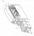
- the electronic component supply device 5 includes a plurality of tape feeders 10 which are aligned in parallel along the conveyance direction of the circuit board. In this manner, the electronic component mounting machine 1 suctions the electronic components supplied from the tape feeder 10 of the electronic component supply device 5 by the suction nozzle of the mounting head 3, moves the mounting head 3 to the circuit board by using the moving device 4, and mounts the electronic components to a predetermined position of the circuit board.
- a left side on a paper surface (a side on which the electronic component mounting machine 1 is present when being installed on the electronic component mounting machine 1) is a front side
- a right side on a paper surface is a rear side
- an upper side on a paper surface (an upper side in the vertical direction when being installed on the electronic component mounting machine 1) is an upper side
- a lower side on a paper surface is a lower side
- the depth direction of a paper surface is the conveyance direction of the circuit board.
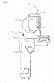
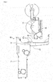
- the tape feeder 10 includes a feeder main body 11, a movable mechanism 12, and a reel holding section 13.
- the tape feeder 10 is a type which is called an auto loading feeder, and holds two reels 51 and 52.
- the first tape (hereinafter, referred to as a feeding tape) at which the electronic component is held at a constant pitch interval, is wound around the first reel 51.
- the second tape (hereinafter, referred to as a waiting tape) at which the electronic component is held at a constant pitch interval, is wound around the second reel 52.
- the electronic components held by the feeding tape, and the electronic components held by the waiting tape are the same type.
- the first reel 51 and the second reel 52 are held at different positions on the reel holding surface orthogonal to the conveyance direction of the circuit board.
- the reel holding surface is also a surface on which the feeder main body 11 is present.
- the feeder main body 11 is configured to be attachable to and detachable from a frame of the electronic component supply device 5, and includes a first sprocket 21 and a second sprocket 22.
- the first sprocket 21 and the second sprocket 22 are configured to be rotatable being synchronized with each other.
- the first sprocket 21 and the second sprocket 22 are engaged with a feeding hole which is formed in the feeding tape from the first reel 51, and pitch-feeds the feeding tape to a component suction position along a tape guide (not illustrated).
- a tip end of the waiting tape from the second reel 52 waits above the second sprocket 22.
- the feeder main body 11 moves the waiting tape which waits above the second sprocket 22 downward, and engages the second sprocket 22 with the feeding hole formed in the waiting tape.
- the feeder main body 11 is configured to automatically feed the waiting tape to the electronic component mounting machine 1 after the feeding tape is consumed, and can omit the splicing work of the tape which has been manually performed. Accordingly, since work efficiency of the worker is improved, and stop of production which is caused when the splicing work is forgotten or missed is prevented, the production efficiency of the electronic component mounting machine 1 is improved.
- the movable mechanism 12 is configured to allow the reel holding section 13 to relatively move with respect to the feeder main body 11, and includes a support arm 31, one pair or links 32 and 33, and a guide arm 34.
- a support arm 31 In the support arm 31, an upper end portion is fixed to a rear end portion of the feeder main body 11, extends in parallel to the reel holding surface, and extends downward from a rear end portion of the feeder main body 11.
- the lower end portion of the support arm 31 includes a connecting section 31a which extends rearward.
- the first link 32 extends in parallel to the reel holding surface, one end thereof is linked to the connecting section 31a of the support arm 31 to be rotatable, and the other end thereof is linked to a front end portion of the guide arm 34 to be rotatable.
- the second link 33 also extends in parallel to the reel holding surface, one end thereof is linked to the connecting section 31a of the support arm 31 to be rotatable, and the other end thereof is linked to the front end portion of the guide arm 34 to be rotatable. Between the connecting section 31a of the support arm 31 and the guide arm 34, the first link 32 and the second link 33 have the same length. Accordingly, the guide arm 34 is configured to be movable in parallel on a surface parallel to the reel holding surface.
- FIGs. 2 and 3 an aspect in which the guide arm 34 moves in parallel is illustrated.
- the movable mechanism 12 can change a position of the reel holding section 13 with respect to the feeder main body 11 between the upper position (refer to Fig. 2 ) and the lower position (refer to Fig. 3 ) by moving the guide arm 34 in parallel by using one pair of links 32 and 33.
- an existence range when the reel holding section 13 and one pair of reels 51 and 52 are the upper position does not overlap an existence range when the reel holding section 13 and one pair of reels 51 and 52 are at the lower position. Therefore, as illustrated in Fig.
- the electronic component mounting machine 1 when the plurality of tape feeders 10 are installed on the electronic component mounting machine 1, if the reel holding section 13 disposed at the upper position and the reel holding section disposed at the lower position are alternately set along the conveyance direction, a contact state of the reel holding section 13 between the adjacent tape feeders 10 are avoided. Since the reel holding section 13 is configured to be wider than the feeder main body 11, by avoiding the contact state of the reel holding section 13, the number of tape feeders 10 which can be installed on the electronic component mounting machine 1 is restricted not by the width of the wide reel holding section 13, but by the width of the narrow feeder main body 11. Accordingly, since more tape feeders 10 can be installed on the electronic component mounting machine 1, the electronic component mounting machine 1 can mount many types of electronic components on the circuit board.
- the reel holding section 13 includes a first holding section 41 and a second holding section 42.
- the first holding section 41 is disposed further toward a near side from the feeder main body 11 than the second holding section 42.
- the first holding section 41 includes an engaging pin 41a, and the engagement pin 41a is engaged with a rotating shaft hole of the first reel 51, and holds the first reel 51 to be rotatable.
- the second holding section 42 is disposed further toward a far side from the feeder main body 11 than the first holding section 41, and is configured of a rectangular plate member. In the second holding section 42, the front end portion is linked to the first holding member 41 to be rotatable.
- the second holding section 42 also includes an engaging pin 42a in the rear end portion, and the engagement pin 42a is engaged with the rotating shaft hole of the second reel 52, and holds the second reel 52 to be rotatable.
- the second holding section 42 When the second holding section 42 is positioned at a position in which the longitudinal direction is parallel to the forward-and-rearward direction, that is, at a position at which the engagement pin 42a is separated the most from the engaging pin 41a of the first holding section 41, the second reel 52 is stably held. Meanwhile, as illustrated in Fig. 4 , for example, in a case where the number of electronic components required for the circuit board to be produced is small, and is sufficient as the electronic components of the first reel 51, the second holding section 42 is folded to the first holding section 41 side, and is accommodated on a side of the first holding section 41. Accordingly, since the width in the forward-and-rearward direction of the tape feeder 10 becomes short, reduction of a space of the electronic component supply device 5 is achieved.
- the first holding section 41 includes one pair of rollers 41b and 41c.
- One pair of rollers 41a and 41b consider the conveyance direction of the circuit board as a rotating shaft, and are inserted into an opening 34a formed in the guide arm 34.
- the opening 34a of the guide arm 34 extends along the forward-and-rearward direction.
- One pair of rollers 41a and 41b move to be guided to the opening 34a of the guide arm 34.
- the reel holding section 13 is configured to be slidable in the forward-and-rearward direction along the guide arm 34, and is configured to be movable between the proximity position that is close to the feeder main body 11 and the separation position that is separated from the feeder main body 11.
- a view in which main portions of the rear end portion of the guide arm 34 are enlarged is schematically illustrated.
- one pair of grooves 35 and 36 including an upper groove 35 formed at an upper edge that defines the opening 34a, and a lower groove 36 formed at a lower edge that defines the opening 34a, are formed.
- the upper groove 35 is formed further forward than the lower groove 36. Since the reel holding section 13 is formed to extend to the rear side from the one pair of rollers 41a and 41b, in the reel holding section 13, a self-weighting torque is generated clockwise considering the one pair of rollers 41a and 41b as a rotating shaft. Therefore, as illustrated in Fig.
- the tape feeder 10 of the embodiment can automatically supply the waiting tape from the second reel 52 to the electronic component mounting machine 1 after the feeding tape from the first reel 51 is consumed. Furthermore, before the waiting tape from the second reel 52 is consumed, the worker takes out the first reel 51 in which the feeding tape is consumed from the first holding section 41, moves the second reel 52 to the first holding section 41, and replenishes new reel to the second holding section 42. Accordingly, since it is not necessary to stop the production for exchanging the reel, production efficiency of the electronic component mounting machine 1 is improved.
- the reel holding section 13 disposed at the upper position and the reel holding section 13 disposed at the lower position are alternately set along the conveyance direction of the circuit board. Therefore, in particular, the first holding section 41 of the reel holding section 13 disposed at the lower position is disturbed by the reel holding section 13 disposed at the upper position when being observed by the worker.
- the reel holding section 13 is configured to be movable between the proximity position and the separation position. Accordingly, when the reel holding section 13 disposed at the lower position is placed at the separation position, since the reel holding section 13 is exposed from the reel holding section 13 disposed at the upper position, it is possible to easily exchange the reel held by the reel holding section 13.
- the guide arm 34 moves in parallel between the upper position and the lower position by using the one pair of links 32 and 33 is illustrated.
- the guide arm 34 may move between the upper position and the lower position by using an attachable and detachable mechanism.
- the support arm 31 which is an example thereof includes one pair of upper engagement hooks 37a and one pair of lower engagement hooks 37b.
- the guide arm 34 includes one pair of engaging pins 38 which are formed in the front end portion. The guide arm 34 is disposed at the upper position when one pair of engaging pins 38 are engaged with the upper engagement hook 37a, and is disposed at the lower position when one pair of engaging pins 38 are engaged with the lower engagement hook 37b.
- the attachable and detachable mechanism achieves a simple aspect, and has characteristics of being strong against damage.
Landscapes
- Engineering & Computer Science (AREA)
- Manufacturing & Machinery (AREA)
- Microelectronics & Electronic Packaging (AREA)
- Supply And Installment Of Electrical Components (AREA)
Applications Claiming Priority (1)
| Application Number | Priority Date | Filing Date | Title |
|---|---|---|---|
| PCT/JP2014/067979 WO2016002085A1 (ja) | 2014-07-04 | 2014-07-04 | テープフィーダ |
Publications (3)
| Publication Number | Publication Date |
|---|---|
| EP3166376A1 true EP3166376A1 (de) | 2017-05-10 |
| EP3166376A4 EP3166376A4 (de) | 2017-07-19 |
| EP3166376B1 EP3166376B1 (de) | 2019-11-27 |
Family
ID=55018681
Family Applications (1)
| Application Number | Title | Priority Date | Filing Date |
|---|---|---|---|
| EP14896345.7A Active EP3166376B1 (de) | 2014-07-04 | 2014-07-04 | Bandzuführung |
Country Status (5)
| Country | Link |
|---|---|
| US (1) | US10375868B2 (de) |
| EP (1) | EP3166376B1 (de) |
| JP (1) | JP6545677B2 (de) |
| CN (1) | CN106471876B (de) |
| WO (1) | WO2016002085A1 (de) |
Families Citing this family (7)
| Publication number | Priority date | Publication date | Assignee | Title |
|---|---|---|---|---|
| KR102061155B1 (ko) * | 2015-04-03 | 2019-12-31 | 야마하하쓰도키 가부시키가이샤 | 셋업 지원 장치, 부품 실장기, 셋업 지원 방법 |
| JP6759457B2 (ja) * | 2017-05-11 | 2020-09-23 | ヤマハ発動機株式会社 | 部品供給台車および部品実装装置 |
| JP7129610B2 (ja) * | 2018-03-30 | 2022-09-02 | パナソニックIpマネジメント株式会社 | 部品供給ユニットの配置決定方法および部品供給ユニットの配置決定装置 |
| US11974402B2 (en) | 2018-06-27 | 2024-04-30 | Yamaha Hatsudoki Kabushiki Kaisha | Component supply device |
| JP6806743B2 (ja) * | 2018-08-24 | 2021-01-06 | ファナック株式会社 | リールホルダ、テープ供給装置、ロボットハンド、ロボットおよび部品実装システム |
| WO2020084663A1 (ja) | 2018-10-22 | 2020-04-30 | 株式会社Fuji | 電気部品供給装置、および電気部品供給方法 |
| DE112021007495T5 (de) * | 2021-04-13 | 2024-02-01 | Fuji Corporation | Zufuhrvorrichtung und Komponentenmontagevorrichtung |
Family Cites Families (11)
| Publication number | Priority date | Publication date | Assignee | Title |
|---|---|---|---|---|
| US5873691A (en) * | 1995-05-11 | 1999-02-23 | Fuji Machine Mfg. Co., Ltd. | Electronic-component supplying system |
| JP4320199B2 (ja) | 2002-05-24 | 2009-08-26 | 富士機械製造株式会社 | テープフィーダおよび電子部品供給システム |
| JP4375193B2 (ja) * | 2004-10-06 | 2009-12-02 | パナソニック株式会社 | 電子部品供給装置 |
| JP2010212681A (ja) * | 2009-03-09 | 2010-09-24 | Koshoku Kin | 部品実装機用キャリアテープ自動供給装置 |
| US8678065B2 (en) * | 2010-03-30 | 2014-03-25 | Sts Co., Ltd. | Carrier tape feeder |
| JP5891353B2 (ja) * | 2012-01-19 | 2016-03-23 | パナソニックIpマネジメント株式会社 | テープフィーダ及び部品実装装置 |
| JP5891354B2 (ja) * | 2012-01-19 | 2016-03-23 | パナソニックIpマネジメント株式会社 | テープフィーダ及び部品実装装置 |
| JP6114509B2 (ja) * | 2012-06-28 | 2017-04-12 | ヤマハ発動機株式会社 | 部品供給装置及び部品実装装置 |
| JP6137975B2 (ja) * | 2012-09-25 | 2017-05-31 | 富士機械製造株式会社 | フィーダ |
| US10660249B2 (en) * | 2015-09-09 | 2020-05-19 | Fuji Corporation | Separate installation-type reel holding device |
| EP3386286B1 (de) * | 2015-11-30 | 2022-06-15 | Fuji Corporation | Energieversorgungssteuerungsvorrichtung und energieversorgungssteuerungsverfahren für einen teilezuführer |
-
2014
- 2014-07-04 JP JP2016530795A patent/JP6545677B2/ja active Active
- 2014-07-04 US US15/323,447 patent/US10375868B2/en active Active
- 2014-07-04 WO PCT/JP2014/067979 patent/WO2016002085A1/ja not_active Ceased
- 2014-07-04 CN CN201480080172.2A patent/CN106471876B/zh active Active
- 2014-07-04 EP EP14896345.7A patent/EP3166376B1/de active Active
Also Published As
| Publication number | Publication date |
|---|---|
| EP3166376B1 (de) | 2019-11-27 |
| US10375868B2 (en) | 2019-08-06 |
| CN106471876B (zh) | 2019-04-23 |
| WO2016002085A1 (ja) | 2016-01-07 |
| EP3166376A4 (de) | 2017-07-19 |
| JP6545677B2 (ja) | 2019-07-17 |
| CN106471876A (zh) | 2017-03-01 |
| JPWO2016002085A1 (ja) | 2017-04-27 |
| US20170142873A1 (en) | 2017-05-18 |
Similar Documents
| Publication | Publication Date | Title |
|---|---|---|
| EP3166376B1 (de) | Bandzuführung | |
| US10743446B2 (en) | Component tape feeder with reel displacing mechanism | |
| CN107950083B (zh) | 追加型带盘保持装置 | |
| CN107950085B (zh) | 另置式带盘保持装置 | |
| JP6040421B2 (ja) | リール保持具および部品実装装置 | |
| JP6554440B2 (ja) | 部品供給装置、部品供給方法および表面実装機 | |
| US11974402B2 (en) | Component supply device | |
| WO2018207329A1 (ja) | 部品供給台車および部品実装装置 | |
| EP3307040B1 (de) | Vorrichtung für haltewerkzeug zur komponentenzuführung | |
| WO2013145039A1 (ja) | テープフィーダ、および、カバーテープ剥離方法 | |
| WO2016038668A1 (ja) | テープフィーダ保持装置 | |
| JPWO2017098628A1 (ja) | リール保持装置 | |
| JP2009105121A (ja) | 表面実装装置 | |
| JP6777792B2 (ja) | テープフィーダ | |
| CN108605429B (zh) | 元件供给装置、元件供给方法及表面安装机 | |
| CN103766018B (zh) | 带式供料器 | |
| JP7047041B2 (ja) | テープフィーダ | |
| JP2020155791A (ja) | 部品供給装置 | |
| JP7174133B2 (ja) | 電子部品装着機 | |
| JP7234433B2 (ja) | 追加形リール保持装置 | |
| EP3484257B1 (de) | Zuführer | |
| EP3873186B1 (de) | Zuführvorrichtung für elektrische komponenten und zuführverfahren für elektrische komponenten |
Legal Events
| Date | Code | Title | Description |
|---|---|---|---|
| STAA | Information on the status of an ep patent application or granted ep patent |
Free format text: STATUS: THE INTERNATIONAL PUBLICATION HAS BEEN MADE |
|
| PUAI | Public reference made under article 153(3) epc to a published international application that has entered the european phase |
Free format text: ORIGINAL CODE: 0009012 |
|
| STAA | Information on the status of an ep patent application or granted ep patent |
Free format text: STATUS: REQUEST FOR EXAMINATION WAS MADE |
|
| 17P | Request for examination filed |
Effective date: 20161229 |
|
| AK | Designated contracting states |
Kind code of ref document: A1 Designated state(s): AL AT BE BG CH CY CZ DE DK EE ES FI FR GB GR HR HU IE IS IT LI LT LU LV MC MK MT NL NO PL PT RO RS SE SI SK SM TR |
|
| AX | Request for extension of the european patent |
Extension state: BA ME |
|
| A4 | Supplementary search report drawn up and despatched |
Effective date: 20170616 |
|
| RIC1 | Information provided on ipc code assigned before grant |
Ipc: H05K 13/04 20060101ALI20170609BHEP Ipc: H05K 13/02 20060101AFI20170609BHEP |
|
| DAX | Request for extension of the european patent (deleted) | ||
| RAP1 | Party data changed (applicant data changed or rights of an application transferred) |
Owner name: FUJI CORPORATION |
|
| RIN1 | Information on inventor provided before grant (corrected) |
Inventor name: OHASHI HIROYASU |
|
| GRAP | Despatch of communication of intention to grant a patent |
Free format text: ORIGINAL CODE: EPIDOSNIGR1 |
|
| STAA | Information on the status of an ep patent application or granted ep patent |
Free format text: STATUS: GRANT OF PATENT IS INTENDED |
|
| INTG | Intention to grant announced |
Effective date: 20190802 |
|
| GRAS | Grant fee paid |
Free format text: ORIGINAL CODE: EPIDOSNIGR3 |
|
| GRAA | (expected) grant |
Free format text: ORIGINAL CODE: 0009210 |
|
| STAA | Information on the status of an ep patent application or granted ep patent |
Free format text: STATUS: THE PATENT HAS BEEN GRANTED |
|
| AK | Designated contracting states |
Kind code of ref document: B1 Designated state(s): AL AT BE BG CH CY CZ DE DK EE ES FI FR GB GR HR HU IE IS IT LI LT LU LV MC MK MT NL NO PL PT RO RS SE SI SK SM TR |
|
| REG | Reference to a national code |
Ref country code: GB Ref legal event code: FG4D |
|
| REG | Reference to a national code |
Ref country code: CH Ref legal event code: EP |
|
| REG | Reference to a national code |
Ref country code: AT Ref legal event code: REF Ref document number: 1208208 Country of ref document: AT Kind code of ref document: T Effective date: 20191215 |
|
| REG | Reference to a national code |
Ref country code: DE Ref legal event code: R096 Ref document number: 602014057660 Country of ref document: DE |
|
| REG | Reference to a national code |
Ref country code: IE Ref legal event code: FG4D |
|
| REG | Reference to a national code |
Ref country code: NL Ref legal event code: MP Effective date: 20191127 |
|
| REG | Reference to a national code |
Ref country code: LT Ref legal event code: MG4D |
|
| PG25 | Lapsed in a contracting state [announced via postgrant information from national office to epo] |
Ref country code: LV Free format text: LAPSE BECAUSE OF FAILURE TO SUBMIT A TRANSLATION OF THE DESCRIPTION OR TO PAY THE FEE WITHIN THE PRESCRIBED TIME-LIMIT Effective date: 20191127 Ref country code: GR Free format text: LAPSE BECAUSE OF FAILURE TO SUBMIT A TRANSLATION OF THE DESCRIPTION OR TO PAY THE FEE WITHIN THE PRESCRIBED TIME-LIMIT Effective date: 20200228 Ref country code: NO Free format text: LAPSE BECAUSE OF FAILURE TO SUBMIT A TRANSLATION OF THE DESCRIPTION OR TO PAY THE FEE WITHIN THE PRESCRIBED TIME-LIMIT Effective date: 20200227 Ref country code: BG Free format text: LAPSE BECAUSE OF FAILURE TO SUBMIT A TRANSLATION OF THE DESCRIPTION OR TO PAY THE FEE WITHIN THE PRESCRIBED TIME-LIMIT Effective date: 20200227 Ref country code: FI Free format text: LAPSE BECAUSE OF FAILURE TO SUBMIT A TRANSLATION OF THE DESCRIPTION OR TO PAY THE FEE WITHIN THE PRESCRIBED TIME-LIMIT Effective date: 20191127 Ref country code: SE Free format text: LAPSE BECAUSE OF FAILURE TO SUBMIT A TRANSLATION OF THE DESCRIPTION OR TO PAY THE FEE WITHIN THE PRESCRIBED TIME-LIMIT Effective date: 20191127 Ref country code: LT Free format text: LAPSE BECAUSE OF FAILURE TO SUBMIT A TRANSLATION OF THE DESCRIPTION OR TO PAY THE FEE WITHIN THE PRESCRIBED TIME-LIMIT Effective date: 20191127 Ref country code: NL Free format text: LAPSE BECAUSE OF FAILURE TO SUBMIT A TRANSLATION OF THE DESCRIPTION OR TO PAY THE FEE WITHIN THE PRESCRIBED TIME-LIMIT Effective date: 20191127 |
|
| PG25 | Lapsed in a contracting state [announced via postgrant information from national office to epo] |
Ref country code: HR Free format text: LAPSE BECAUSE OF FAILURE TO SUBMIT A TRANSLATION OF THE DESCRIPTION OR TO PAY THE FEE WITHIN THE PRESCRIBED TIME-LIMIT Effective date: 20191127 Ref country code: IS Free format text: LAPSE BECAUSE OF FAILURE TO SUBMIT A TRANSLATION OF THE DESCRIPTION OR TO PAY THE FEE WITHIN THE PRESCRIBED TIME-LIMIT Effective date: 20200327 Ref country code: RS Free format text: LAPSE BECAUSE OF FAILURE TO SUBMIT A TRANSLATION OF THE DESCRIPTION OR TO PAY THE FEE WITHIN THE PRESCRIBED TIME-LIMIT Effective date: 20191127 |
|
| PG25 | Lapsed in a contracting state [announced via postgrant information from national office to epo] |
Ref country code: AL Free format text: LAPSE BECAUSE OF FAILURE TO SUBMIT A TRANSLATION OF THE DESCRIPTION OR TO PAY THE FEE WITHIN THE PRESCRIBED TIME-LIMIT Effective date: 20191127 |
|
| PG25 | Lapsed in a contracting state [announced via postgrant information from national office to epo] |
Ref country code: CZ Free format text: LAPSE BECAUSE OF FAILURE TO SUBMIT A TRANSLATION OF THE DESCRIPTION OR TO PAY THE FEE WITHIN THE PRESCRIBED TIME-LIMIT Effective date: 20191127 Ref country code: ES Free format text: LAPSE BECAUSE OF FAILURE TO SUBMIT A TRANSLATION OF THE DESCRIPTION OR TO PAY THE FEE WITHIN THE PRESCRIBED TIME-LIMIT Effective date: 20191127 Ref country code: RO Free format text: LAPSE BECAUSE OF FAILURE TO SUBMIT A TRANSLATION OF THE DESCRIPTION OR TO PAY THE FEE WITHIN THE PRESCRIBED TIME-LIMIT Effective date: 20191127 Ref country code: EE Free format text: LAPSE BECAUSE OF FAILURE TO SUBMIT A TRANSLATION OF THE DESCRIPTION OR TO PAY THE FEE WITHIN THE PRESCRIBED TIME-LIMIT Effective date: 20191127 Ref country code: PT Free format text: LAPSE BECAUSE OF FAILURE TO SUBMIT A TRANSLATION OF THE DESCRIPTION OR TO PAY THE FEE WITHIN THE PRESCRIBED TIME-LIMIT Effective date: 20200419 Ref country code: DK Free format text: LAPSE BECAUSE OF FAILURE TO SUBMIT A TRANSLATION OF THE DESCRIPTION OR TO PAY THE FEE WITHIN THE PRESCRIBED TIME-LIMIT Effective date: 20191127 |
|
| REG | Reference to a national code |
Ref country code: DE Ref legal event code: R097 Ref document number: 602014057660 Country of ref document: DE |
|
| PG25 | Lapsed in a contracting state [announced via postgrant information from national office to epo] |
Ref country code: SM Free format text: LAPSE BECAUSE OF FAILURE TO SUBMIT A TRANSLATION OF THE DESCRIPTION OR TO PAY THE FEE WITHIN THE PRESCRIBED TIME-LIMIT Effective date: 20191127 Ref country code: SK Free format text: LAPSE BECAUSE OF FAILURE TO SUBMIT A TRANSLATION OF THE DESCRIPTION OR TO PAY THE FEE WITHIN THE PRESCRIBED TIME-LIMIT Effective date: 20191127 |
|
| REG | Reference to a national code |
Ref country code: AT Ref legal event code: MK05 Ref document number: 1208208 Country of ref document: AT Kind code of ref document: T Effective date: 20191127 |
|
| PLBE | No opposition filed within time limit |
Free format text: ORIGINAL CODE: 0009261 |
|
| STAA | Information on the status of an ep patent application or granted ep patent |
Free format text: STATUS: NO OPPOSITION FILED WITHIN TIME LIMIT |
|
| 26N | No opposition filed |
Effective date: 20200828 |
|
| PG25 | Lapsed in a contracting state [announced via postgrant information from national office to epo] |
Ref country code: AT Free format text: LAPSE BECAUSE OF FAILURE TO SUBMIT A TRANSLATION OF THE DESCRIPTION OR TO PAY THE FEE WITHIN THE PRESCRIBED TIME-LIMIT Effective date: 20191127 Ref country code: PL Free format text: LAPSE BECAUSE OF FAILURE TO SUBMIT A TRANSLATION OF THE DESCRIPTION OR TO PAY THE FEE WITHIN THE PRESCRIBED TIME-LIMIT Effective date: 20191127 Ref country code: SI Free format text: LAPSE BECAUSE OF FAILURE TO SUBMIT A TRANSLATION OF THE DESCRIPTION OR TO PAY THE FEE WITHIN THE PRESCRIBED TIME-LIMIT Effective date: 20191127 |
|
| PG25 | Lapsed in a contracting state [announced via postgrant information from national office to epo] |
Ref country code: IT Free format text: LAPSE BECAUSE OF FAILURE TO SUBMIT A TRANSLATION OF THE DESCRIPTION OR TO PAY THE FEE WITHIN THE PRESCRIBED TIME-LIMIT Effective date: 20191127 |
|
| PG25 | Lapsed in a contracting state [announced via postgrant information from national office to epo] |
Ref country code: MC Free format text: LAPSE BECAUSE OF FAILURE TO SUBMIT A TRANSLATION OF THE DESCRIPTION OR TO PAY THE FEE WITHIN THE PRESCRIBED TIME-LIMIT Effective date: 20191127 |
|
| REG | Reference to a national code |
Ref country code: CH Ref legal event code: PL |
|
| GBPC | Gb: european patent ceased through non-payment of renewal fee |
Effective date: 20200704 |
|
| REG | Reference to a national code |
Ref country code: BE Ref legal event code: MM Effective date: 20200731 |
|
| PG25 | Lapsed in a contracting state [announced via postgrant information from national office to epo] |
Ref country code: GB Free format text: LAPSE BECAUSE OF NON-PAYMENT OF DUE FEES Effective date: 20200704 Ref country code: IE Free format text: LAPSE BECAUSE OF NON-PAYMENT OF DUE FEES Effective date: 20200704 Ref country code: CH Free format text: LAPSE BECAUSE OF NON-PAYMENT OF DUE FEES Effective date: 20200731 Ref country code: LU Free format text: LAPSE BECAUSE OF NON-PAYMENT OF DUE FEES Effective date: 20200704 Ref country code: LI Free format text: LAPSE BECAUSE OF NON-PAYMENT OF DUE FEES Effective date: 20200731 Ref country code: FR Free format text: LAPSE BECAUSE OF NON-PAYMENT OF DUE FEES Effective date: 20200731 |
|
| PG25 | Lapsed in a contracting state [announced via postgrant information from national office to epo] |
Ref country code: BE Free format text: LAPSE BECAUSE OF NON-PAYMENT OF DUE FEES Effective date: 20200731 |
|
| PG25 | Lapsed in a contracting state [announced via postgrant information from national office to epo] |
Ref country code: TR Free format text: LAPSE BECAUSE OF FAILURE TO SUBMIT A TRANSLATION OF THE DESCRIPTION OR TO PAY THE FEE WITHIN THE PRESCRIBED TIME-LIMIT Effective date: 20191127 Ref country code: MT Free format text: LAPSE BECAUSE OF FAILURE TO SUBMIT A TRANSLATION OF THE DESCRIPTION OR TO PAY THE FEE WITHIN THE PRESCRIBED TIME-LIMIT Effective date: 20191127 Ref country code: CY Free format text: LAPSE BECAUSE OF FAILURE TO SUBMIT A TRANSLATION OF THE DESCRIPTION OR TO PAY THE FEE WITHIN THE PRESCRIBED TIME-LIMIT Effective date: 20191127 |
|
| PG25 | Lapsed in a contracting state [announced via postgrant information from national office to epo] |
Ref country code: MK Free format text: LAPSE BECAUSE OF FAILURE TO SUBMIT A TRANSLATION OF THE DESCRIPTION OR TO PAY THE FEE WITHIN THE PRESCRIBED TIME-LIMIT Effective date: 20191127 |
|
| P01 | Opt-out of the competence of the unified patent court (upc) registered |
Effective date: 20230328 |
|
| PGFP | Annual fee paid to national office [announced via postgrant information from national office to epo] |
Ref country code: DE Payment date: 20250528 Year of fee payment: 12 |