EP3166751B1 - Dispositif de compression servant à comprimer une bande de finition sur les surfaces de pièces - Google Patents
Dispositif de compression servant à comprimer une bande de finition sur les surfaces de pièces Download PDFInfo
- Publication number
- EP3166751B1 EP3166751B1 EP15733407.9A EP15733407A EP3166751B1 EP 3166751 B1 EP3166751 B1 EP 3166751B1 EP 15733407 A EP15733407 A EP 15733407A EP 3166751 B1 EP3166751 B1 EP 3166751B1
- Authority
- EP
- European Patent Office
- Prior art keywords
- pressure belt
- pressing device
- bearing pin
- workpiece
- carrier
- Prior art date
- Legal status (The legal status is an assumption and is not a legal conclusion. Google has not performed a legal analysis and makes no representation as to the accuracy of the status listed.)
- Active
Links
Images



Classifications
-
- B—PERFORMING OPERATIONS; TRANSPORTING
- B24—GRINDING; POLISHING
- B24B—MACHINES, DEVICES, OR PROCESSES FOR GRINDING OR POLISHING; DRESSING OR CONDITIONING OF ABRADING SURFACES; FEEDING OF GRINDING, POLISHING, OR LAPPING AGENTS
- B24B19/00—Single-purpose machines or devices for particular grinding operations not covered by any other main group
- B24B19/08—Single-purpose machines or devices for particular grinding operations not covered by any other main group for grinding non-circular cross-sections, e.g. shafts of elliptical or polygonal cross-section
- B24B19/12—Single-purpose machines or devices for particular grinding operations not covered by any other main group for grinding non-circular cross-sections, e.g. shafts of elliptical or polygonal cross-section for grinding cams or camshafts
-
- B—PERFORMING OPERATIONS; TRANSPORTING
- B24—GRINDING; POLISHING
- B24B—MACHINES, DEVICES, OR PROCESSES FOR GRINDING OR POLISHING; DRESSING OR CONDITIONING OF ABRADING SURFACES; FEEDING OF GRINDING, POLISHING, OR LAPPING AGENTS
- B24B21/00—Machines or devices using grinding or polishing belts; Accessories therefor
- B24B21/004—Machines or devices using grinding or polishing belts; Accessories therefor using abrasive rolled strips
-
- B—PERFORMING OPERATIONS; TRANSPORTING
- B24—GRINDING; POLISHING
- B24B—MACHINES, DEVICES, OR PROCESSES FOR GRINDING OR POLISHING; DRESSING OR CONDITIONING OF ABRADING SURFACES; FEEDING OF GRINDING, POLISHING, OR LAPPING AGENTS
- B24B21/00—Machines or devices using grinding or polishing belts; Accessories therefor
- B24B21/02—Machines or devices using grinding or polishing belts; Accessories therefor for grinding rotationally symmetrical surfaces
-
- B—PERFORMING OPERATIONS; TRANSPORTING
- B24—GRINDING; POLISHING
- B24B—MACHINES, DEVICES, OR PROCESSES FOR GRINDING OR POLISHING; DRESSING OR CONDITIONING OF ABRADING SURFACES; FEEDING OF GRINDING, POLISHING, OR LAPPING AGENTS
- B24B21/00—Machines or devices using grinding or polishing belts; Accessories therefor
- B24B21/18—Accessories
-
- B—PERFORMING OPERATIONS; TRANSPORTING
- B24—GRINDING; POLISHING
- B24B—MACHINES, DEVICES, OR PROCESSES FOR GRINDING OR POLISHING; DRESSING OR CONDITIONING OF ABRADING SURFACES; FEEDING OF GRINDING, POLISHING, OR LAPPING AGENTS
- B24B35/00—Machines or devices designed for superfinishing surfaces on work, i.e. by means of abrading blocks reciprocating with high frequency
-
- B—PERFORMING OPERATIONS; TRANSPORTING
- B24—GRINDING; POLISHING
- B24B—MACHINES, DEVICES, OR PROCESSES FOR GRINDING OR POLISHING; DRESSING OR CONDITIONING OF ABRADING SURFACES; FEEDING OF GRINDING, POLISHING, OR LAPPING AGENTS
- B24B5/00—Machines or devices designed for grinding surfaces of revolution on work, including those which also grind adjacent plane surfaces; Accessories therefor
- B24B5/36—Single-purpose machines or devices
- B24B5/42—Single-purpose machines or devices for grinding crankshafts or crankpins
Definitions
- the invention relates to a pressing device for pressing a finishing strip against a workpiece surface, comprising a pressure belt and a Andschreibbandango, which supports the pressure belt at two spaced support points, wherein the pressure belt is releasably secured to the Andschreibbandany.
- the present invention has the object to provide a pressing device with which the non-productive times of a device for finishing machining a workpiece can be shortened.
- fixing devices are provided, which can be fastened or fastened detachably to the pressure belt, wherein these fixing devices make it possible to fix the pressure belt ends to the respective fixing device independently of the pressure belt carrier.
- fixing devices make it possible to connect a Andschreibbandende with a fixing device, so that the Andschreibbandende is fixed in the fixing device, this process spatially outside a device for finishing machining of a workpiece, and only then the fixing is attached to the Andschreibbandango.
- leadandschreibb which are already fixed to separate fixing devices, are kept ready to replace in the event of damage to a Andschreibbands the damaged Andschreibband including fixing against a new Andschreibband, which is already fixed in two other fixing devices.
- the time-consuming set-up operations associated with the handling of a pressure belt are spatially decoupled from the pressure belt carrier of a finishing machining apparatus such that the time-consuming handling operations can be performed during operation of the finishing apparatus, ie during the main times of the finishing apparatus .
- the non-productive times, which are associated with the installation of a pressure band, are thus shortened to a period of time, which are required for releasably securing the fixing means on the Andschreibbandango and for releasing the fixing means of the Andschreibbandany.
- a particularly reliable fixation of the Andschreibbands on the fixing results when the fixing device as Clamping device is formed.
- the fixing device as Clamping device is formed.
- the fixed end of the Andschreibbands and the fixing device are not movable relative to each other.
- a particularly good fixation of the Andschreibbands on the fixing device results when the fixing device has a clamping surface delimited by two clamping surfaces for receiving a Andschreibbandendes.
- two fixing devices together with the pressure belt form a mounting group which can be mounted as a whole on the Andschreibbandango and detachable from the Andschreibbandologi.
- the respective ends of the pressing belt are fixed to or within a respective fixing device, so that no relative movement between the pressing belt end and the fixing device is possible in the connecting region between the pressing belt end and the fixing device.
- the fixing devices can still be changed relative to each other in terms of their position and location, namely by the pressure band is elastically deformed. This simplifies the assembly of the assembly group on the Andschreibbandany and also the disassembly of the assembly of the Andschreibbanditati.
- a plug connection is provided for the detachable connection of the fixing device to the Andschreibbandany. This allows a particularly quick and easy installation of a fixing device on the Andschreibbandany.
- the plug connection preferably comprises a plug in the form of a bearing pin and a plug receptacle in the form of a bearing pin receptacle.
- the bearing pin and the Make bearing pin receptacle a pivot bearing.
- the connecting portions for connecting the fixing device and the Andschreibbandzis fulfill an additional function, which makes it possible to pivotally mount a fixing device on the Andschreibbandany.
- Such a pivotability has the advantage that a pressure band is at least largely tension-free on the Andschreibbandzi can be arranged.
- the axis of the pivot bearing extends perpendicular to a rotational axis of a workpiece to be machined.
- a particularly simple constructed pressing device is obtained when the bearing pin is formed on the Andschreibbandiki and when the bearing pin receptacle is formed on the fixing device.
- the bearing pin receptacle along a circumference of their bearing pin receiving surface has an opening that the bearing pin along a circumference of its bearing pin surface with respect to a cylindrical shape has a taper and that the taper and the opening are mutually available.
- the Andschreibbandzi is integrally formed.
- the Andschreibbandzi is multi-part and comprises a base support for releasably securing the fixing means and a movably mounted on the base support additional element, by means of which the support points are provided. In this way, a further degree of freedom is created, which allows a tension-free arrangement of the Andschreibbands on the Andschreibbandany.
- the additional element is mounted pivotably about an additional element pivot axis on the base support. In this way, the support points can be pivoted relative to the base support.
- the additional element pivot axis runs parallel to a rotation axis of a workpiece to be machined. This makes it possible to work by means of the same pressing device workpieces with different diameters, with the additional element to the 1925elementschwenkachse depending on the diameter of a workpiece to be machined on the base carrier aligns.
- FIG. 1 shows a device 10 for finish machining a workpiece 12.
- the workpiece 12 is, for example, a crankshaft, which rotates about a rotation axis 14 in the course of their finishing.
- the workpiece surface 16 to be machined is, for example, a main bearing surface or a connecting rod bearing surface.
- a finishing belt 18 is provided, which is taken from a supply 20 and is supplied by means of a first guide device 22 to a first pressing device 24 and a deflection point 26. Starting from the deflection point 26, the finishing belt 18 is fed to a second pressure device 28 and a second guide device 30 and finally to a collector 32.
- the pressing devices 24 and 28 are held on opposite sides of the workpiece 12 respectively on pivot arms 34, 36, which are pivotable about respective support arm pivot axes 38, 40.
- the support arm pivot axes 38, 40 are stationary relative to a frame part 42.
- the frame part 42 also serves to arrange a drive device 44, which is known per se and is therefore only shown in sections.
- the drive device 44 serves to press the pincer-like holding arms 34, 36 in each case with the pressing device 24 or 28 held thereon in the direction of the workpiece 12.
- the workpiece 12 In the course of machining the workpiece 12 this rotates around the Rotation axis 14.
- the finishing belt 18 is pressed at the level of the pressing devices 24, 28 against the workpiece surface 16 to be machined.
- the rotational movement of the workpiece 12 is superimposed on the rotational axis 14 by an oscillating linear movement.
- the workpiece 12 oscillates along the axis of rotation 14 relative to the finishing belt 18. It is possible, the workpiece 12 and / or the finishing belt 18 to drive oscillating. This oscillation movement produces a cross-cut structure characteristic of a finishing process.
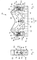
- the structure of the pressing means 24, 28 and their connection to the holding arms 34, 36 will be described below with reference to FIG. 2 explained.
- the holding arms 34, 36 have free ends 46, 48, to each of which a base support 50 of a pressing device 24, 28 is fastened by means of a screw 51.
- the base support 50 has a base 52 and protruding from the base 52 arms 54 and 56. Between the arms 54 and 56 is formed along the base 52 extending free space, which serves for the arrangement of a bearing block 58.
- the bearing block 58 is used for pivotal mounting of a V-shaped additional element 60. Accordingly, the additional element 60 is pivotally mounted about an additional element pivot axis 62 on the base support 50 of the pressing device 24, 28.
- the V-shaped additional element 60 has in each case at its free ends rounded support points 64, 66, which serve to support the back of a Andschreibbands 68.
- the pressure belt 68 is slidably mounted in the region of the support points 64, 66.
- the pressing belt 68 transmits with its front side a pressing force on the back side of the finishing belt 18, so that its front side is pressed against the workpiece surface 16 of the workpiece 12.
- the pivotable mounting of the additional element 60 makes it possible for different sized workpieces 12 (see. Figures 2 and 3 ) to compensate for different opening angles of the holding arms 34, 36, so that a finishing effective portion 70 of the finishing belt 18 respectively is aligned centrally between the support points 64, 66. This is also possible because the additional element pivot axis 62 extends parallel to the axis of rotation 14 of the workpiece 12.
- a pivot pin 72 is provided for pivotal mounting of the additional part 60 to the base support 50.
- the pivot pin 72 cooperates with a locking screw 74, which fixes the additional part 60 to the pivot pin 72.
- the additional element 60, the pivot pin 72 and the locking screw 74 form a pivoting group, which is pivoted together about the additional element pivot axis 62.
- two fixing devices 78, 80 are provided, which are preferably constructed identically and each serve to fix a Andschreibbandende 82, 84 of the Andschreibbands 68.
- the fixing devices 78, 80 are designed as clamping devices and each have a clamping slot 86 for receiving a Andschreibbandendes 82 and 84 on.
- the Andschreibbandenden 82, 84 have a hole 88 for the passage of a clamping screw 90.
- the clamping screw 90 serves to move on both sides of the clamping slot 86 material portions 92 and 94 of a fixing device 78, 80 zuzubewegen to narrow the clamping slot 86, so that each of the Andschreibbandende 82 and 84 facing surfaces of the material portions 92, 94 form clamping surfaces.
- delimiting the clamping slot 86 in the lateral direction delimiting elements 96 are provided, which are screwed, for example, with the material portion 94.
- the material sections 92 and 94 are integrally formed with a further material section 98 of a fixing device 78, 80.
- the connector 100 includes a plug in the form of a bearing pin 102, which is preferably arranged on each one of the arms 54, 56 of the Andschreibbandanys 76.
- the bearing pin 102 cooperates with a connector receptacle in the form of a bearing pin receptacle 104. This is formed by the material section 98 of the fixing device 78, 80.
- the bearing pin 102 and the bearing pin receptacle 104 together form a pivot bearing 106 with an axis 108 which is orthogonal to the axis of rotation 14 of the workpiece 12.
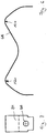
- Andrückbands 68 on the Andschreibbandzi 76 is a preformed Andschreibband (see. FIGS. 6 and 7 ) are first connected to two fixing devices 78, 80 by the Andschreibbandenden 82 and 84 are each clamped in a clamping slot 86 of the fixing means 78, 80.
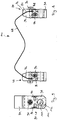
- a mounting group 110 consisting of a pressing belt 68 and two fixing devices 78, 80, compare FIG. 8 ,
- bearing pin receptacle 104 are hollow cylindrical and the bearing pin 102 are cylindrical in order to jointly form a plug connection 100.
- a bearing pin receiving surface 112 of the bearing pin receptacle 104 seen in the circumferential direction has an opening 114 (see. FIG. 9 ).
- This opening 114 serves to be able to introduce the bearing pin 102 in the lateral direction in the bearing pin receptacle 104.
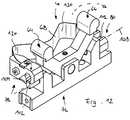
- the bearing pin 102 along a circumference of its bearing pin surface 116 with respect to a cylindrical shape a taper 118, see FIGS. 10 to 12 ,
- the assembly 110 is positioned relative to the Andschreibbandany 76 that a first fixing device 80 can be joined with its bearing pin receptacle 104 with a first bearing pin 102.
- the opening 114 of the bearing pin receptacle 104 of the first fixing device 80 is aligned so that it can be plugged onto the taper 118 of a first bearing pin 102.
- the first fixing device 80 is releasably secured to the Andschreibbandany 76, see FIGS. 10 and 11 ,
- the second fixing device 78 can then be joined to the Andschreibbandani 76 by the mounting assembly 110 is pivoted by 180 ° about the pivot axis 108 of the first fixing device 80 (see. Figures 11 and 12 ). In this way, the opening 114 of the bearing pin receptacle 104 of the second fixing device 78 can be brought in the joining position with the second bearing pin 102 of the Andschreibbandanys 76 (see. FIG. 12 ). On this basis, the second bearing pin 102 and the bearing pin receptacle 104 of the second fixing device 78 can be joined together, as indicated by a dashed arrow in FIG FIG. 12 is indicated.
- the pressure belt 68 is based on its power-free output form (see 6 and 7 ) deformed, in particular bent and / or twisted. This is an elastic deformation.
Landscapes
- Engineering & Computer Science (AREA)
- Mechanical Engineering (AREA)
- Finish Polishing, Edge Sharpening, And Grinding By Specific Grinding Devices (AREA)
- Constituent Portions Of Griding Lathes, Driving, Sensing And Control (AREA)
- Automatic Assembly (AREA)
- Treatment Of Fiber Materials (AREA)
- Folding Of Thin Sheet-Like Materials, Special Discharging Devices, And Others (AREA)
Claims (14)
- Dispositif de pression (24) destine à presser une bande de finition (18) contre une surface de pièce (16), comprenant une bande de pression (68) et un support de bande de pression (76) qui supporte la bande de pression (68) sur deux points de support (64, 66) espacés l'un de l'autre, la bande de pression (68) étant fixée de manière amovible au support de bande de pression (76), caractérisé par le fait que, pour fixer respectivement une extrémité (82, 84) de la bande de pression, un dispositif de fixation (78, 80) est prévu séparément du support de bande de pression (76), et que le dispositif de fixation (78, 80) peut être ou est fixé de manière amovible au support de bande de pression (76) dans un état dans lequel une extrémité (82, 84) de la bande de pression est fixée au dispositif de fixation (78, 80).
- Dispositif de pression (24) selon la revendication 1, caractérisé par le fait que ledit dispositif de fixation (78, 80) est réalisé en tant que dispositif de serrage.
- Dispositif de pression (24) selon l'une quelconque des revendications précédentes, caractérisé par le fait que ledit dispositif de fixation (78, 80) présente une fente de serrage (86) délimitée par deux surfaces de serrage et destinée à loger une extrémité de bande de pression (82, 84).
- Dispositif de pression (24) selon la revendication 3, caractérisé par le fait que ledit dispositif de fixation (78, 80) présente des éléments de limitation (96) destinés à délimiter latéralement ladite fente de serrage (86).
- Dispositif de pression (24) selon l'une quelconque des revendications précédentes, caractérisé par le fait que deux dispositifs de fixation (78, 80) forment conjointement avec la bande de pression (68) un groupe de montage (110) qui, en tant qu'ensemble, peut être monté sur le support de bande de pression (76) et être détaché du support de bande de pression (76).
- Dispositif de pression (24) selon l'une quelconque des revendications précédentes, caractérisé par le fait qu'un assemblage mâle-femelle (100) est prévu pour la liaison amovible du dispositif de fixation (78, 80) au support de bande de pression (76).
- Dispositif de pression (24) selon la revendication 6, caractérisé par le fait que l'assemblage mâle-femelle (100) comprend une partie mâle sous forme d'un pivot (102) et une partie femelle sous forme d'un logement de pivot (104).
- Dispositif de pression (24) selon la revendication 7, caractérisé par le fait que ledit pivot (102) et ledit logement de pivot (104) forment un palier de pivotement (106).
- Dispositif de pression (24) selon la revendication 8, caractérisé par le fait que l'axe (108) du palier de pivotement (106) s'étend perpendiculairement à un axe de rotation (14) d'une pièce (12) à usiner.
- Dispositif de pression (24) selon l'une quelconque des revendications 7 à 9, caractérisé par le fait que le pivot (102) est réalisé sur le support de bande de pression (76) et que le logement de pivot (104) est réalisé sur le dispositif de fixation (78, 80).
- Dispositif de pression (24) selon l'une quelconque des revendications 7 à 10, caractérisé par le fait que le logement de pivot (104) présente une percée (114) le long d'une circonférence de sa surface de logement de pivot (112), que le pivot (102) présente, par rapport à une forme cylindrique, un rétrécissement (118) le long d'une circonférence de sa surface de pivot (116) et que le rétrécissement (118) et la percée (114) peuvent être joints l'un avec l'autre.
- Dispositif de pression (24) selon l'une quelconque des revendications précédentes, caractérisé par le fait que le support de bande de pression (76) est réalisé en plusieurs parties et comprend un support de base (50) pour la fixation amovible du dispositif de fixation (78, 80) ainsi qu'un élément supplémentaire (60) qui est logé de manière mobile sur ledit support de base (50) et au moyen duquel sont fournis lesdits points de support (64, 66).
- Dispositif de pression (24) selon la revendication 12, caractérisé par le fait que ledit élément supplémentaire (60) est logé à pivotement autour d'un axe de pivotement d'élément supplémentaire (62) sur le support de base (50).
- Dispositif de pression (24) selon la revendication 13, caractérisé par le fait que ledit axe de pivotement d'élément supplémentaire (62) s'étend parallèlement à un axe de rotation (14) d'une pièce (12) à usiner.
Applications Claiming Priority (2)
| Application Number | Priority Date | Filing Date | Title |
|---|---|---|---|
| DE102014213194.4A DE102014213194A1 (de) | 2014-07-08 | 2014-07-08 | Andrückeinrichtung zum Andrücken eines Finisbands gegen eine Werkstückoberfläche |
| PCT/EP2015/064372 WO2016005193A1 (fr) | 2014-07-08 | 2015-06-25 | Dispositif de pression pour presser une bande de finition contre la surface d'une pièce |
Publications (2)
| Publication Number | Publication Date |
|---|---|
| EP3166751A1 EP3166751A1 (fr) | 2017-05-17 |
| EP3166751B1 true EP3166751B1 (fr) | 2018-03-28 |
Family
ID=53498988
Family Applications (1)
| Application Number | Title | Priority Date | Filing Date |
|---|---|---|---|
| EP15733407.9A Active EP3166751B1 (fr) | 2014-07-08 | 2015-06-25 | Dispositif de compression servant à comprimer une bande de finition sur les surfaces de pièces |
Country Status (6)
| Country | Link |
|---|---|
| US (1) | US9744639B2 (fr) |
| EP (1) | EP3166751B1 (fr) |
| KR (1) | KR101752148B1 (fr) |
| CN (1) | CN106457505B (fr) |
| DE (1) | DE102014213194A1 (fr) |
| WO (1) | WO2016005193A1 (fr) |
Families Citing this family (8)
| Publication number | Priority date | Publication date | Assignee | Title |
|---|---|---|---|---|
| DE102015216357A1 (de) | 2015-08-27 | 2017-03-02 | Supfina Grieshaber Gmbh & Co. Kg | Umfangsflächenbearbeitungseinheit, Werkzeugmaschine und Verfahren zum Betrieb |
| DE102016107965A1 (de) * | 2016-04-29 | 2017-11-02 | Supfina Grieshaber Gmbh & Co. Kg | Bandfinishvorrichtung |
| DE102016116325A1 (de) | 2016-09-01 | 2018-03-01 | Supfina Grieshaber Gmbh & Co. Kg | Vorrichtung, System und Verfahren zur Ausrichtung mindestens eines an einem zangenförmigen Andrückarm einer Finishbearbeitungseinheit gehaltenen Finish- oder Andrückwerkzeugs |
| DE102017201120B3 (de) | 2017-01-24 | 2018-06-21 | Nagel Maschinen- Und Werkzeugfabrik Gmbh | Andrückeinrichtung für Finishband und Bandfinishvorrichtung |
| DE102017108191A1 (de) | 2017-04-18 | 2018-10-18 | Rud. Starcke Gmbh & Co. Kg | Verfahren zum partiellen Schleifen einer Oberfläche sowie Schleifeinrichtung |
| CN112247772B (zh) * | 2020-10-21 | 2021-10-22 | 佛山市维通金属制品有限公司 | 一种便携式不锈钢管焊缝均匀打磨装置 |
| DE102022212676A1 (de) * | 2022-11-28 | 2024-05-29 | Nagel Maschinen- und Werkzeugfabrik Gesellschaft mit beschränkter Haftung. | Finishverfahren, Finishmaschine und Finishkopf |
| CN116944996B (zh) * | 2023-09-19 | 2023-11-24 | 江苏诚品环保科技有限公司 | 一种多层实木地板抛光去毛刺设备 |
Family Cites Families (11)
| Publication number | Priority date | Publication date | Assignee | Title |
|---|---|---|---|---|
| US3566549A (en) * | 1969-01-21 | 1971-03-02 | James A Britton | Flexible all purpose drill attachment |
| US4682444A (en) * | 1984-05-07 | 1987-07-28 | Industrial Metal Products Corporation | Microfinishing apparatus and method |
| DE4444239C3 (de) * | 1994-12-13 | 2003-05-08 | Supfina Grieshaber Gmbh & Co | Feinstbearbeitungsmaschine |
| JP3661712B2 (ja) * | 1995-11-13 | 2005-06-22 | トヨタ自動車株式会社 | ラップ加工装置 |
| DE19921043C2 (de) * | 1999-05-07 | 2002-09-19 | Juergen Heesemann | Bandschleifmaschine |
| JP4156200B2 (ja) * | 2001-01-09 | 2008-09-24 | 株式会社荏原製作所 | 研磨装置及び研磨方法 |
| DE10332605B4 (de) * | 2003-07-17 | 2005-09-15 | Ibz Gmbh | Anpressvorrichtung für eine Oberflächenbearbeitungsvorrichtung |
| DE10342139B4 (de) * | 2003-09-12 | 2008-06-19 | Thielenhaus Technologies Gmbh | Verfahren zur Finishbearbeitung von Umfangsflächen an wellenförmigen Werkstücken |
| DE102007051047B4 (de) | 2007-10-16 | 2023-03-23 | Nagel Maschinen- Und Werkzeugfabrik Gmbh | Andrückeinrichtung für Finishband sowie Vorrichtung und Verfahren zur Finishbearbeitung von Umfangsflächen an zylindrischen Werkstückabschnitten |
| DE202013005504U1 (de) | 2013-06-12 | 2013-06-26 | Nagel Maschinen- Und Werkzeugfabrik Gmbh | Andrückeinrichtung für Finishband sowie Vorrichtung zur Finishbearbeitung von Umfangsflächen an zylindrischen Werkstückabschnitten |
| DE202014000094U1 (de) * | 2014-01-13 | 2014-02-18 | Supfina Grieshaber Gmbh & Co. Kg | Andrückeinrichtung |
-
2014
- 2014-07-08 DE DE102014213194.4A patent/DE102014213194A1/de not_active Withdrawn
-
2015
- 2015-06-25 EP EP15733407.9A patent/EP3166751B1/fr active Active
- 2015-06-25 KR KR1020177003204A patent/KR101752148B1/ko active Active
- 2015-06-25 WO PCT/EP2015/064372 patent/WO2016005193A1/fr not_active Ceased
- 2015-06-25 CN CN201580029217.8A patent/CN106457505B/zh active Active
- 2015-06-25 US US15/319,804 patent/US9744639B2/en active Active
Also Published As
| Publication number | Publication date |
|---|---|
| KR20170020534A (ko) | 2017-02-22 |
| US20170151645A1 (en) | 2017-06-01 |
| KR101752148B1 (ko) | 2017-07-11 |
| CN106457505A (zh) | 2017-02-22 |
| EP3166751A1 (fr) | 2017-05-17 |
| WO2016005193A1 (fr) | 2016-01-14 |
| CN106457505B (zh) | 2018-06-12 |
| US9744639B2 (en) | 2017-08-29 |
| DE102014213194A1 (de) | 2016-01-28 |
Similar Documents
| Publication | Publication Date | Title |
|---|---|---|
| WO2016005193A1 (fr) | Dispositif de pression pour presser une bande de finition contre la surface d'une pièce | |
| DE69301352T2 (de) | Vorrichtung zum Spannen und Festhalten von zu formenden Glasscheiben in ihrer Position während ihrer Bearbeitung | |
| EP0999911A1 (fr) | Dispositif pour la separation par rupture de la barre et du chapeau d'une bielle | |
| DE112013000583B4 (de) | Sägeblattspannvorrichtung | |
| DE102012108031A1 (de) | Halter für eine Fügevorrichtung | |
| DE2630498C3 (de) | Einstellbarer Halter | |
| EP1977124B1 (fr) | Dispositif pour maintenir et positionner des appareils, des pièces et des outils | |
| EP3172012B1 (fr) | Dispositif de finition | |
| EP2097199B1 (fr) | Dispositif pendulaire et procédé associé | |
| DE2851308C2 (de) | Vorrichtung zum Einstemmen von Lagerbüchsen | |
| DE102021120815B4 (de) | Verfahren und selbstzentrierende fixiervorrichtung zum fixieren einer schweissvorrichtung an einem rohrabschnitt | |
| EP2929988B1 (fr) | Dispositif de marquage pour coupe-tubes | |
| EP1743743B1 (fr) | Écarteur | |
| DE2905689C2 (fr) | ||
| DE10203389A1 (de) | Spannvorrichtung | |
| DE102012104660B4 (de) | Greiferbackenanordnung | |
| EP2865488B1 (fr) | Machine à meuler à bande dotée de modules à meuler à bande pouvant être couplés entre eux | |
| DE102005043211A1 (de) | Fügevorrichtung zum umformtechnischen Fügen | |
| DE202016105061U1 (de) | Werkzeug, insbesondere für die spanabhebende Werkstückbearbeitung | |
| DE102019121380A1 (de) | Schweißbrenner | |
| EP2905106B1 (fr) | Système de serrage et de positionnement au point zéro | |
| DE102013012313A1 (de) | Haltevorrichtung zum Fixieren und/oder Verspannen von zumindest zwei Bauteilen | |
| DE202018105777U1 (de) | Haltevorrichtung für das Halten mindestens eines Bauteils | |
| DE102015220963A1 (de) | Anordnung zur lagegesicherten Verbindung zweier Teile | |
| DE102009011331A1 (de) | Axial geteiltes Ringmesser für eine Längsschneidevorrichtung |
Legal Events
| Date | Code | Title | Description |
|---|---|---|---|
| PUAI | Public reference made under article 153(3) epc to a published international application that has entered the european phase |
Free format text: ORIGINAL CODE: 0009012 |
|
| 17P | Request for examination filed |
Effective date: 20161115 |
|
| AK | Designated contracting states |
Kind code of ref document: A1 Designated state(s): AL AT BE BG CH CY CZ DE DK EE ES FI FR GB GR HR HU IE IS IT LI LT LU LV MC MK MT NL NO PL PT RO RS SE SI SK SM TR |
|
| AX | Request for extension of the european patent |
Extension state: BA ME |
|
| REG | Reference to a national code |
Ref country code: DE Ref legal event code: R079 Ref document number: 502015003647 Country of ref document: DE Free format text: PREVIOUS MAIN CLASS: B24B0005420000 Ipc: B24B0021180000 |
|
| DAV | Request for validation of the european patent (deleted) | ||
| DAX | Request for extension of the european patent (deleted) | ||
| GRAP | Despatch of communication of intention to grant a patent |
Free format text: ORIGINAL CODE: EPIDOSNIGR1 |
|
| RIC1 | Information provided on ipc code assigned before grant |
Ipc: B24B 21/00 20060101ALI20171010BHEP Ipc: B24B 35/00 20060101ALI20171010BHEP Ipc: B24B 21/02 20060101ALI20171010BHEP Ipc: B24B 19/12 20060101ALI20171010BHEP Ipc: B24B 5/42 20060101ALI20171010BHEP Ipc: B24B 21/18 20060101AFI20171010BHEP |
|
| INTG | Intention to grant announced |
Effective date: 20171031 |
|
| GRAS | Grant fee paid |
Free format text: ORIGINAL CODE: EPIDOSNIGR3 |
|
| GRAA | (expected) grant |
Free format text: ORIGINAL CODE: 0009210 |
|
| AK | Designated contracting states |
Kind code of ref document: B1 Designated state(s): AL AT BE BG CH CY CZ DE DK EE ES FI FR GB GR HR HU IE IS IT LI LT LU LV MC MK MT NL NO PL PT RO RS SE SI SK SM TR |
|
| REG | Reference to a national code |
Ref country code: GB Ref legal event code: FG4D Free format text: NOT ENGLISH |
|
| REG | Reference to a national code |
Ref country code: CH Ref legal event code: EP |
|
| REG | Reference to a national code |
Ref country code: AT Ref legal event code: REF Ref document number: 982972 Country of ref document: AT Kind code of ref document: T Effective date: 20180415 |
|
| REG | Reference to a national code |
Ref country code: IE Ref legal event code: FG4D Free format text: LANGUAGE OF EP DOCUMENT: GERMAN |
|
| REG | Reference to a national code |
Ref country code: DE Ref legal event code: R096 Ref document number: 502015003647 Country of ref document: DE |
|
| PG25 | Lapsed in a contracting state [announced via postgrant information from national office to epo] |
Ref country code: LT Free format text: LAPSE BECAUSE OF FAILURE TO SUBMIT A TRANSLATION OF THE DESCRIPTION OR TO PAY THE FEE WITHIN THE PRESCRIBED TIME-LIMIT Effective date: 20180328 Ref country code: HR Free format text: LAPSE BECAUSE OF FAILURE TO SUBMIT A TRANSLATION OF THE DESCRIPTION OR TO PAY THE FEE WITHIN THE PRESCRIBED TIME-LIMIT Effective date: 20180328 Ref country code: NO Free format text: LAPSE BECAUSE OF FAILURE TO SUBMIT A TRANSLATION OF THE DESCRIPTION OR TO PAY THE FEE WITHIN THE PRESCRIBED TIME-LIMIT Effective date: 20180628 Ref country code: FI Free format text: LAPSE BECAUSE OF FAILURE TO SUBMIT A TRANSLATION OF THE DESCRIPTION OR TO PAY THE FEE WITHIN THE PRESCRIBED TIME-LIMIT Effective date: 20180328 |
|
| REG | Reference to a national code |
Ref country code: NL Ref legal event code: MP Effective date: 20180328 |
|
| REG | Reference to a national code |
Ref country code: LT Ref legal event code: MG4D |
|
| PG25 | Lapsed in a contracting state [announced via postgrant information from national office to epo] |
Ref country code: LV Free format text: LAPSE BECAUSE OF FAILURE TO SUBMIT A TRANSLATION OF THE DESCRIPTION OR TO PAY THE FEE WITHIN THE PRESCRIBED TIME-LIMIT Effective date: 20180328 Ref country code: SE Free format text: LAPSE BECAUSE OF FAILURE TO SUBMIT A TRANSLATION OF THE DESCRIPTION OR TO PAY THE FEE WITHIN THE PRESCRIBED TIME-LIMIT Effective date: 20180328 Ref country code: GR Free format text: LAPSE BECAUSE OF FAILURE TO SUBMIT A TRANSLATION OF THE DESCRIPTION OR TO PAY THE FEE WITHIN THE PRESCRIBED TIME-LIMIT Effective date: 20180629 Ref country code: BG Free format text: LAPSE BECAUSE OF FAILURE TO SUBMIT A TRANSLATION OF THE DESCRIPTION OR TO PAY THE FEE WITHIN THE PRESCRIBED TIME-LIMIT Effective date: 20180628 Ref country code: RS Free format text: LAPSE BECAUSE OF FAILURE TO SUBMIT A TRANSLATION OF THE DESCRIPTION OR TO PAY THE FEE WITHIN THE PRESCRIBED TIME-LIMIT Effective date: 20180328 |
|
| PG25 | Lapsed in a contracting state [announced via postgrant information from national office to epo] |
Ref country code: MT Free format text: LAPSE BECAUSE OF FAILURE TO SUBMIT A TRANSLATION OF THE DESCRIPTION OR TO PAY THE FEE WITHIN THE PRESCRIBED TIME-LIMIT Effective date: 20180328 |
|
| PG25 | Lapsed in a contracting state [announced via postgrant information from national office to epo] |
Ref country code: IT Free format text: LAPSE BECAUSE OF FAILURE TO SUBMIT A TRANSLATION OF THE DESCRIPTION OR TO PAY THE FEE WITHIN THE PRESCRIBED TIME-LIMIT Effective date: 20180328 Ref country code: AL Free format text: LAPSE BECAUSE OF FAILURE TO SUBMIT A TRANSLATION OF THE DESCRIPTION OR TO PAY THE FEE WITHIN THE PRESCRIBED TIME-LIMIT Effective date: 20180328 Ref country code: NL Free format text: LAPSE BECAUSE OF FAILURE TO SUBMIT A TRANSLATION OF THE DESCRIPTION OR TO PAY THE FEE WITHIN THE PRESCRIBED TIME-LIMIT Effective date: 20180328 Ref country code: PL Free format text: LAPSE BECAUSE OF FAILURE TO SUBMIT A TRANSLATION OF THE DESCRIPTION OR TO PAY THE FEE WITHIN THE PRESCRIBED TIME-LIMIT Effective date: 20180328 Ref country code: EE Free format text: LAPSE BECAUSE OF FAILURE TO SUBMIT A TRANSLATION OF THE DESCRIPTION OR TO PAY THE FEE WITHIN THE PRESCRIBED TIME-LIMIT Effective date: 20180328 Ref country code: ES Free format text: LAPSE BECAUSE OF FAILURE TO SUBMIT A TRANSLATION OF THE DESCRIPTION OR TO PAY THE FEE WITHIN THE PRESCRIBED TIME-LIMIT Effective date: 20180328 Ref country code: RO Free format text: LAPSE BECAUSE OF FAILURE TO SUBMIT A TRANSLATION OF THE DESCRIPTION OR TO PAY THE FEE WITHIN THE PRESCRIBED TIME-LIMIT Effective date: 20180328 |
|
| PG25 | Lapsed in a contracting state [announced via postgrant information from national office to epo] |
Ref country code: SM Free format text: LAPSE BECAUSE OF FAILURE TO SUBMIT A TRANSLATION OF THE DESCRIPTION OR TO PAY THE FEE WITHIN THE PRESCRIBED TIME-LIMIT Effective date: 20180328 Ref country code: CZ Free format text: LAPSE BECAUSE OF FAILURE TO SUBMIT A TRANSLATION OF THE DESCRIPTION OR TO PAY THE FEE WITHIN THE PRESCRIBED TIME-LIMIT Effective date: 20180328 Ref country code: SK Free format text: LAPSE BECAUSE OF FAILURE TO SUBMIT A TRANSLATION OF THE DESCRIPTION OR TO PAY THE FEE WITHIN THE PRESCRIBED TIME-LIMIT Effective date: 20180328 |
|
| PG25 | Lapsed in a contracting state [announced via postgrant information from national office to epo] |
Ref country code: PT Free format text: LAPSE BECAUSE OF FAILURE TO SUBMIT A TRANSLATION OF THE DESCRIPTION OR TO PAY THE FEE WITHIN THE PRESCRIBED TIME-LIMIT Effective date: 20180730 |
|
| REG | Reference to a national code |
Ref country code: DE Ref legal event code: R097 Ref document number: 502015003647 Country of ref document: DE |
|
| PG25 | Lapsed in a contracting state [announced via postgrant information from national office to epo] |
Ref country code: DK Free format text: LAPSE BECAUSE OF FAILURE TO SUBMIT A TRANSLATION OF THE DESCRIPTION OR TO PAY THE FEE WITHIN THE PRESCRIBED TIME-LIMIT Effective date: 20180328 |
|
| REG | Reference to a national code |
Ref country code: CH Ref legal event code: PL |
|
| PLBE | No opposition filed within time limit |
Free format text: ORIGINAL CODE: 0009261 |
|
| STAA | Information on the status of an ep patent application or granted ep patent |
Free format text: STATUS: NO OPPOSITION FILED WITHIN TIME LIMIT |
|
| 26N | No opposition filed |
Effective date: 20190103 |
|
| REG | Reference to a national code |
Ref country code: BE Ref legal event code: MM Effective date: 20180630 |
|
| REG | Reference to a national code |
Ref country code: IE Ref legal event code: MM4A |
|
| PG25 | Lapsed in a contracting state [announced via postgrant information from national office to epo] |
Ref country code: LU Free format text: LAPSE BECAUSE OF NON-PAYMENT OF DUE FEES Effective date: 20180625 Ref country code: MC Free format text: LAPSE BECAUSE OF FAILURE TO SUBMIT A TRANSLATION OF THE DESCRIPTION OR TO PAY THE FEE WITHIN THE PRESCRIBED TIME-LIMIT Effective date: 20180328 |
|
| PG25 | Lapsed in a contracting state [announced via postgrant information from national office to epo] |
Ref country code: LI Free format text: LAPSE BECAUSE OF NON-PAYMENT OF DUE FEES Effective date: 20180630 Ref country code: FR Free format text: LAPSE BECAUSE OF NON-PAYMENT OF DUE FEES Effective date: 20180630 Ref country code: IE Free format text: LAPSE BECAUSE OF NON-PAYMENT OF DUE FEES Effective date: 20180625 Ref country code: CH Free format text: LAPSE BECAUSE OF NON-PAYMENT OF DUE FEES Effective date: 20180630 |
|
| PG25 | Lapsed in a contracting state [announced via postgrant information from national office to epo] |
Ref country code: SI Free format text: LAPSE BECAUSE OF FAILURE TO SUBMIT A TRANSLATION OF THE DESCRIPTION OR TO PAY THE FEE WITHIN THE PRESCRIBED TIME-LIMIT Effective date: 20180328 Ref country code: BE Free format text: LAPSE BECAUSE OF NON-PAYMENT OF DUE FEES Effective date: 20180630 |
|
| PG25 | Lapsed in a contracting state [announced via postgrant information from national office to epo] |
Ref country code: TR Free format text: LAPSE BECAUSE OF FAILURE TO SUBMIT A TRANSLATION OF THE DESCRIPTION OR TO PAY THE FEE WITHIN THE PRESCRIBED TIME-LIMIT Effective date: 20180328 |
|
| PG25 | Lapsed in a contracting state [announced via postgrant information from national office to epo] |
Ref country code: CY Free format text: LAPSE BECAUSE OF FAILURE TO SUBMIT A TRANSLATION OF THE DESCRIPTION OR TO PAY THE FEE WITHIN THE PRESCRIBED TIME-LIMIT Effective date: 20180328 Ref country code: HU Free format text: LAPSE BECAUSE OF FAILURE TO SUBMIT A TRANSLATION OF THE DESCRIPTION OR TO PAY THE FEE WITHIN THE PRESCRIBED TIME-LIMIT; INVALID AB INITIO Effective date: 20150625 Ref country code: MK Free format text: LAPSE BECAUSE OF NON-PAYMENT OF DUE FEES Effective date: 20180328 |
|
| PG25 | Lapsed in a contracting state [announced via postgrant information from national office to epo] |
Ref country code: IS Free format text: LAPSE BECAUSE OF FAILURE TO SUBMIT A TRANSLATION OF THE DESCRIPTION OR TO PAY THE FEE WITHIN THE PRESCRIBED TIME-LIMIT Effective date: 20180728 |
|
| REG | Reference to a national code |
Ref country code: AT Ref legal event code: MM01 Ref document number: 982972 Country of ref document: AT Kind code of ref document: T Effective date: 20200625 |
|
| PG25 | Lapsed in a contracting state [announced via postgrant information from national office to epo] |
Ref country code: AT Free format text: LAPSE BECAUSE OF NON-PAYMENT OF DUE FEES Effective date: 20200625 |
|
| P01 | Opt-out of the competence of the unified patent court (upc) registered |
Effective date: 20230621 |
|
| PGFP | Annual fee paid to national office [announced via postgrant information from national office to epo] |
Ref country code: DE Payment date: 20250618 Year of fee payment: 11 |
|
| PGFP | Annual fee paid to national office [announced via postgrant information from national office to epo] |
Ref country code: GB Payment date: 20250620 Year of fee payment: 11 |