EP3167249B1 - Neutralteil für einen kundenspezifisch adaptierbaren sensor - Google Patents
Neutralteil für einen kundenspezifisch adaptierbaren sensor Download PDFInfo
- Publication number
- EP3167249B1 EP3167249B1 EP15788333.1A EP15788333A EP3167249B1 EP 3167249 B1 EP3167249 B1 EP 3167249B1 EP 15788333 A EP15788333 A EP 15788333A EP 3167249 B1 EP3167249 B1 EP 3167249B1
- Authority
- EP
- European Patent Office
- Prior art keywords
- sensor
- protective compound
- protective
- compound
- signal
- Prior art date
- Legal status (The legal status is an assumption and is not a legal conclusion. Google has not performed a legal analysis and makes no representation as to the accuracy of the status listed.)
- Active
Links
Images



Classifications
-
- G—PHYSICS
- G01—MEASURING; TESTING
- G01D—MEASURING NOT SPECIALLY ADAPTED FOR A SPECIFIC VARIABLE; ARRANGEMENTS FOR MEASURING TWO OR MORE VARIABLES NOT COVERED IN A SINGLE OTHER SUBCLASS; TARIFF METERING APPARATUS; MEASURING OR TESTING NOT OTHERWISE PROVIDED FOR
- G01D5/00—Mechanical means for transferring the output of a sensing member; Means for converting the output of a sensing member to another variable where the form or nature of the sensing member does not constrain the means for converting; Transducers not specially adapted for a specific variable
- G01D5/12—Mechanical means for transferring the output of a sensing member; Means for converting the output of a sensing member to another variable where the form or nature of the sensing member does not constrain the means for converting; Transducers not specially adapted for a specific variable using electric or magnetic means
- G01D5/244—Mechanical means for transferring the output of a sensing member; Means for converting the output of a sensing member to another variable where the form or nature of the sensing member does not constrain the means for converting; Transducers not specially adapted for a specific variable using electric or magnetic means influencing characteristics of pulses or pulse trains; generating pulses or pulse trains
- G01D5/245—Mechanical means for transferring the output of a sensing member; Means for converting the output of a sensing member to another variable where the form or nature of the sensing member does not constrain the means for converting; Transducers not specially adapted for a specific variable using electric or magnetic means influencing characteristics of pulses or pulse trains; generating pulses or pulse trains using a variable number of pulses in a train
-
- G—PHYSICS
- G01—MEASURING; TESTING
- G01D—MEASURING NOT SPECIALLY ADAPTED FOR A SPECIFIC VARIABLE; ARRANGEMENTS FOR MEASURING TWO OR MORE VARIABLES NOT COVERED IN A SINGLE OTHER SUBCLASS; TARIFF METERING APPARATUS; MEASURING OR TESTING NOT OTHERWISE PROVIDED FOR
- G01D11/00—Component parts of measuring arrangements not specially adapted for a specific variable
- G01D11/24—Housings ; Casings for instruments
- G01D11/245—Housings for sensors
-
- G—PHYSICS
- G01—MEASURING; TESTING
- G01D—MEASURING NOT SPECIALLY ADAPTED FOR A SPECIFIC VARIABLE; ARRANGEMENTS FOR MEASURING TWO OR MORE VARIABLES NOT COVERED IN A SINGLE OTHER SUBCLASS; TARIFF METERING APPARATUS; MEASURING OR TESTING NOT OTHERWISE PROVIDED FOR
- G01D5/00—Mechanical means for transferring the output of a sensing member; Means for converting the output of a sensing member to another variable where the form or nature of the sensing member does not constrain the means for converting; Transducers not specially adapted for a specific variable
- G01D5/12—Mechanical means for transferring the output of a sensing member; Means for converting the output of a sensing member to another variable where the form or nature of the sensing member does not constrain the means for converting; Transducers not specially adapted for a specific variable using electric or magnetic means
- G01D5/14—Mechanical means for transferring the output of a sensing member; Means for converting the output of a sensing member to another variable where the form or nature of the sensing member does not constrain the means for converting; Transducers not specially adapted for a specific variable using electric or magnetic means influencing the magnitude of a current or voltage
- G01D5/16—Mechanical means for transferring the output of a sensing member; Means for converting the output of a sensing member to another variable where the form or nature of the sensing member does not constrain the means for converting; Transducers not specially adapted for a specific variable using electric or magnetic means influencing the magnitude of a current or voltage by varying resistance
Definitions
- the invention relates to a method for producing a sensor circuit and the sensor circuit.
- a sensor with a sensor circuit is known, which is connected to a wiring carrier called the base element during the manufacture of the sensor.
- the wiring carrier is held in a holding frame called a band and forms a so-called leadframe in one piece with it.
- DE 10 2013 202212 A1 discloses a sensor with a circuit carrier, on the assembly island of which a sensor element and an ASIC are arranged and embedded in a first housing made of duroplast, with the first housing and the contact connections being partially encased in a second protective compound made of overmold.
- the object is achieved by the method according to claim 1 and by the sensor according to claim 2.
- a method for producing a sensor with a circuit carrier comprises a has a sensor circuit for outputting a pick-and-place island that carries a sensor signal that is dependent on a physical sensor field and an interface that is electrically connected to the pick-and-place island for sending the sensor signal to a higher-level signal processing device, the steps of encasing a part of the circuit carrier that contains the pick-and-place island and the sensor circuit in a first protective ground, connecting a signal transmission element to the interface and encasing at least part of the first protective compound and the interface with at least a part of the signal transmission element connected thereto in a second protective compound.
- the method specified is based on the consideration that the sensor must have a mechanical interface in order to attach the sensor to a superordinate sensor carrier, such as a vehicle.
- the sensor also requires an electrical interface in order to feed the sensor signal from the sensor circuit into the signal transmission element, which transmits the sensor signal to a higher-order signal processing circuit, such as an engine control of the aforementioned vehicle.
- the mechanical interface is generally formed in a protective compound that protects the electrical interface and the sensor circuit from mechanical stresses and other influences, such as weathering, in order to manufacture the sensor with as few production steps as possible.
- the specified method is also based on the consideration that the mechanical interface usually has to be designed customer-specifically because the installation space of the higher-level sensor carrier, like the aforementioned vehicle, depends on the customer's specifications. Sensors that are therefore to be installed in small numbers in higher-level sensor carriers can therefore only be mass-produced with difficulty.
- the specified method comes into play here with the consideration of separating the housing of the electrical interface to the sensor circuit in a protective ground and the formation of a mechanical interface in the protective ground.
- a neutral part can first be manufactured for the sensor, in which the electrical interface is protected with a protective ground.
- the neutral part for the sensor can be transported and can then be transported to a production facility where the neutral part for the sensor can be brought into a form adapted to the specific installation space in a customer-specific manner.
- the neutral part itself can be mass-produced at low cost, regardless of the customer-specific shape. Only at a very late stage of production does the sensor need to be adapted to the customer-specific installation space with the customer-specific mechanical interface in a special production in a more cost-intensive manner.
- the signal processing element can also be designed as desired, for example, as an antenna for wireless transmission of the sensor signal.
- the signal transmission element is a cable.
- the specified method is particularly favorable here because cables generally place heavy demands on the electrical interface in an unprotected manner. With the specified method, in the course of which the neutral part is first manufactured, in which the electrical interface is protected in the protective mass, the sensor can be transported without any problems in this intermediate production stage even if the transmission element is a cable.
- the neutral part After the neutral part has been manufactured within the scope of the specified sensor, the neutral part can be transported to a further production site in a further development of the specified method, with at least part of the second protective compound being encased in a third protective compound.
- this third protective mass can then be designed in a special development with a fastening section as a mechanical interface for fastening the sensor to the already mentioned sensor carrier.
- the fastening section comprises a sleeve which is radially enveloped by the third protective mass.
- a sensor is manufactured by one of the specified methods.
- the specified sensor can be a wheel speed sensor or an inertial sensor for a vehicle.
- a vehicle includes a specified sensor.
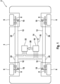
- the vehicle 2 comprises a chassis 4 and four wheels 6. Each wheel 6 can be slowed down relative to the chassis 4 via a brake 8 fixed in a stationary manner to the chassis 4 in order to prevent movement of the Vehicle 2 to slow down on a road not shown.
- ABS anti-lock braking system
- ESP electronic stability program
- the vehicle 2 has speed sensors 10 on the wheels 6 for this purpose, which detect a speed 12 of the wheels 6 .
- Vehicle 2 also has an inertial sensor 14, which detects driving dynamics data 16 of vehicle 2, from which, for example, a pitch rate, a roll rate, a yaw rate, a lateral acceleration, a longitudinal acceleration and/or a vertical acceleration can be output in a manner known per se to a person skilled in the art .
- a controller 18 can determine in a manner known to those skilled in the art whether the vehicle 2 is slipping on the roadway or is even deviating from the above-mentioned predetermined trajectory and can react to this with a controller output signal 20 that is known per se.
- the controller output signal 20 can then be used by a control device 22 in order to control actuators, such as the brakes 8, by means of control signals 24, which respond to the slip and the deviation from the predetermined trajectory in a manner known per se.
- the regulator 18 can be integrated, for example, in an engine control system of the vehicle 2 that is known per se.
- the regulator 18 and the adjusting device 22 can also be designed as a common regulating device and can optionally be integrated into the aforementioned engine control.
- the wheel speed sensor 10 shown is intended to illustrate the present invention in more detail, even if the present invention can be implemented on any sensors, such as magnetic field sensors, acceleration sensors, yaw rate sensors, structure-borne noise sensors or temperature sensors.
- speed sensor 10 is embodied as an active speed sensor, which includes a sensor element in the form of an encoder disc 26 fixed in a rotationally fixed manner on wheel 6 and a sensor circuit fixed in place on chassis 4, which is referred to below as read head 28 for the sake of simplicity.
- the encoder disc 26 consists of magnetic north poles 30 and magnetic south poles 32 lined up in a row, which together excite a physical field in the form of a transmitter magnetic field 33 .
- This encoder magnetic field is in 3 indicated for the sake of clarity with two dashed field lines. If the encoder disc 26 attached to the wheel 6 rotates with it in a direction of rotation 34, the encoder magnetic field rotates as well.
- the read head 28 includes a sensor, also called a measuring transducer, in the form of a magnetoresistive element 35.
- the magnetostrictive element 35 changes its electrical resistance depending on the angular position of the encoder magnetic field 33 excited by the encoder wheel 26.
- a test signal 39 is applied to the magnetoresistive element 35 in order to detect the rotational speed 12 , which signal is changed as a function of the angular position of the encoder wheel 26 and thus of the electrical resistance of the magnetoresistive element 35 .
- a signal evaluation circuit 40 evaluates rotational speed 12 and outputs it to controller 18 in the form of a data signal 42.
- This signal evaluation circuit 40 can also be part of the read head 28 in the form of an application-specific integrated circuit called an ASIC.
- an ASIC application-specific integrated circuit
- any measuring sensor capable of outputting a signal as a function of a magnetic field for example a Hall element, can be used to detect the rotating transmitter magnetic field 33.
- FIG. 1 shows a schematic representation of the read head 28 for the speed sensor 10 in a first intermediate production state.
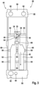
- the read head 28 of the present embodiment is held on a circuit carrier designed as a so-called leadframe 44 . From this leadframe 44 is in 3 only part shown.
- the leadframe 44 can particularly preferably be designed as an endless belt to which the in 3 Part of the leadframe 44 shown next to each other and / or one above the other connects. An example of this is in 4 shown.
- the part of the leadframe 44 shown comprises a holding frame 46, a wiring carrier in the form of an assembly island 48 on which the read head 28 is held and connected, two webs called tiebars 50 and two contact terminals 52.
- the tiebars 50 hold the contact terminals 52 directly and the assembly island 48 on the holding frame 46.
- the holding frame 46, the placement island 48, the tie bars 50 and the contact terminals 52 are designed as a one-piece stamped part or stamped frame, in which the aforementioned elements are formed by stamping from an electrically conductive sheet metal.
- the measuring sensor in the form of the magnetoresistive element 35 and the signal evaluation circuit 40 are mounted on the placement island 48 and electrically contacted, for example by soldering or gluing.
- the magnetoresistive element 35 and the signal evaluation circuit 40 are also connected to one another via a bonding wire 54 so that the test signal 39 can be transmitted via the placement island 48 and the bonding wire 54 between the magnetoresistive element 35 and the signal evaluation circuit 40 .
- the placement island 48 is connected directly to one of the two contact connections 52 , while the other of the two contact connections 52 is electrically isolated from the placement island 48 and connected to the signal evaluation circuit 40 via a further bonding wire 54 .
- the data signal 42 can be output from the signal evaluation circuit 40 via the two contact terminals 56 .
- a passive filter component 66 can be connected between the contact connections 52 in order to filter undesired external signals from and/or into the reading head 28 . Depending on the type of sensor and the number of contact connections 52, several passive filter components 66 can also be connected.
- the holding frame 46 has two transport stiffeners 58 running parallel to one another, which are connected to one another via connecting webs 60 .
- Transport holes 62 are formed on the transport strip 58, into which a transport tool (not shown) can engage and move the leadframe 44.
- an index hole 64 is formed on the transport strip 58, by means of which the position of the leadframe 44 can be determined and thus regulated during transport.
- a part of the leadframe 44 can be designed as a protective plate in a manner that is not shown in any more detail.
- This protective plate could be used for thermal insulation of the reading head 28 during the later enclosing process to be described later, as a mechanical fastening surface for the reading head 28 (by means of adhesive), as a pressure abutment for the reading head 28 during the enclosing process to be described later, as a heat dissipation shield during operation and as an EMC shield for the reading head 28.
- the pick-and-place island 48 with the components 35, 40 carried thereon and optionally the passive filter component 66 can each be housed in a manner known per se in a first protective compound 68, for example made of a duroplastic mold compound.
- a first protective compound 68 for example made of a duroplastic mold compound.
- molding can be used, for example, in the course of which a duroplastic plastic mass is pressed around the circuit carrier in a special tool.
- An epoxy resin for example, can be used as the duroplastic compound.
- a material should be chosen with properties that exert only low stress on the electrical components 35, 40, 66 while at the same time having good adhesion to the leadframe 44.
- a magnet can also be accommodated in the first protective mass 68, which magnet can be used, for example, as a supporting magnet within the scope of barber pole technology.
- the magnet could also be glued onto the first protective compound 68 after it has been housed in it.
- outwardly protruding support webs could also be accommodated or molded in the first protective mass 68 become. These could be used to fix the reading head 28 during further manufacture.
- the support webs support the read head particularly in cases where a large magnet is supported in or on the first protective mass 68 which could cause deflection due to gravity. If the support webs are made of an electrically conductive material, care should be taken to ensure that they do not come into electrical contact with the electrical components of the reading head 28 .
- the placement island 48 encased together with the components 35 , 40 can be partially punched free by separating the corresponding tie bars 50 and thus separated from the holding frame 46 .
- the contact terminals 52 can also be partially punched free. All other elements of the reading head 28 initially remain connected to the holding frame 46 via the tie bars 50 in this manufacturing state.
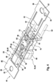
- the pick and place island 48 encased and punched free together with the components 35, 40 and the punched free contact connections 52 in the in 4 can be optionally bent in the manner shown.
- the punched-out and bent assembly island 48 housed together with the components 35, 40 are shown in purple or dotted and the punched-out and bent contact connections are shown in purple/orange or dotted.
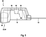
- the reading head 28 which is still partially held on the holding frame 46, is housed in an intermediate protective compound 70 and is then completely punched free from the holding frame 46.
- the encapsulation takes place within the scope of a molding process described above, in which a duroplast can likewise be used as the material for the intermediate protective compound 70 .
- the intermediate protective mass 70 primarily ensures that the curved read head is held securely.
- a calibration can be carried out in the state completely held in the leadframe 44, in the partially punched-out state, or in the punched-out state.
- Punching free immediately before calibration has the advantage that the manufacturing tolerances are very low and also very reproducible.
- the free punching of the reading head 28 should be in the intermediate production state 4 also be done in two steps. After the first stamping step, the supply and signal lines are released and can be electrically contacted. In this case, the test or adjustment/calibration can still take place in the leadframe 44, which has advantages in terms of handling and positioning. Only then does the complete punching out of the holding frame 46 and possibly no further referenced supply pins (preferably ground pin) take place.
- the traceability of the reading head 28 can be ensured by applying a consecutive serial number to the leadframe 44 (e.g. a data matrix code) at the beginning of the production process.
- the production history time stamp, system numbers, measured process values, calibration values, test results, etc.
- this serial number can be stored under this serial number.
- this serial number can be stored in a non-volatile memory of the read head 28 (not shown in more detail). Additionally, this serial number may be applied to the surface of the readhead 28 at any intermediate production or final stage of the readhead 28. In the event of complaints, the affected number ranges can be narrowed down and treated separately.
- the process and material optimization can be operated effectively via a statistical data evaluation.
- housing in the intermediate protective mass 70 can be omitted if the reading head 28 not, as in 4 shown, is bent at its leadframe 44.
- recesses 72 or troughs are formed, which will be discussed in more detail later.
- the recesses 72 can be formed as part of the aforementioned primary forming process.
- the recesses 72 can, in principle, also be formed in subsequently.
- the recesses 72 could also be formed in the leadframe 44, for example as eyelets.
- contours can be provided for safe handling during production, such as flat surfaces as a possibility for a suction nozzle or contours for a gripper.
- the side of the read head 28 in the intermediate production state figure 5 or 6 Aprons are formed, which bring about a lateral adjustment, heat protection, mechanical protection against the flow pressure of the intermediate protective mass 70 and/or the first protective mass 68 and, in the case of any slots introduced, a fixation of the read head 28.
- a bead can be embossed to stabilize any welding conditions.
- the bead can have the shape of a round dome or a longitudinal web.
- a signal transmission element in the form of a data cable 74 is connected after the enclosure with the intermediate protective ground 70 . This can be done in any way, such as crimping, welding, soldering, splicing, gluing or the like.
- a so-called flash can form on a sealing edge of the shells of the mold tool if there are tolerance fluctuations in the material of the leadframe 44 .
- This flash can be removed mechanically by brushing or by an air jet stream or by means of a laser.
- This second protective compound 78 can be a thermoplastic, for example.
- the encapsulation in the second protective compound can take place as part of a primary shaping process, such as injection molding.
- a thermoplastic such as a liquid crystal polymer called LCP, a polyphenylene sulfide called PPS, a polyamide called PA or a polybutylene terephthalate called PBT could be used as the material.
- LCP liquid crystal polymer
- PPS polyphenylene sulfide
- PA polyamide
- PBT polybutylene terephthalate
- support pins 76 are used, on which the read head 28 is held when encased with the second protective compound 78.
- the sensor head 28 is not only supported by the support pins 76 when it is housed in the second protective mass 78 but is also aligned in a specific direction.
- the support pins 76 are removed again, so that the recesses 72 remain not only in the intermediate protective compound 70 or first protective compound 68 but also in the second protective compound 78 .
- gap-extending geometries can exist between the first protective compound 68 or the intermediate protective compound 70 and the second protective compound 78 , such as an uneven surface of the first protective compound 68 or the intermediate protective compound 70 are formed in order to lengthen the path for moisture penetrating into the recesses 72 and thus between the adjacent masses 68, 70, 78.
- the sensor head 28 In the intermediate production state of the 8 the sensor head 28 is already fully functional electrically and could be connected to a superordinate electronic device, such as the controller 18 . However, in order to install the sensor head 28 in the vehicle 2 , a mechanical interface must still be created in order to attach the sensor 2 to the chassis 4 . However, this mechanical interface depends on the installation space of the vehicle 2 .
- the sensor head 28 in the intermediate production state of 8 can in principle be used in any vehicle 2 from an electrical point of view and should therefore be referred to as a so-called neutral part.
- This neutral part can be transported, stored or distributed in any way. It can then be easily adapted to the installation space of the vehicle 2 by adding an in 9 mechanical interface 80 shown as an example can be adapted to the installation space of the vehicle 2 .
- this is to the neutral part of the 8 a third protective mass 82 formed by a primary molding process, such as an injection molding process.
- a sleeve 84 is formed into this third protective mass 82 , through which a fastening means, such as a screw for fastening the read head 28 to the vehicle 2 , can later be guided.
- a clamp 86 can be placed around the molded third protective mass 82, around which the mechanical hold of the third protective mass 82 on the neutral part of the 8 elevated.
Landscapes
- Physics & Mathematics (AREA)
- General Physics & Mathematics (AREA)
- Transmission And Conversion Of Sensor Element Output (AREA)
- Measuring Fluid Pressure (AREA)
Description
- Die Erfindung betrifft ein Verfahren zum Herstellen einer Sensorschaltung und die Sensorschaltung.
- Aus der
WO 2010 / 037 810 A1 ist ein Sensor mit einer Sensorschaltung bekannt, die bei der Herstellung des Sensors auf einem Basiselement genannten Verdrahtungsträger verschaltet wird. Bei der Herstellung der Sensorschaltung ist der Verdrahtungsträger in einem Band genannten Halterahmen gehalten und bildet mit diesem einstückig einen sogenannten Leadframe aus.DE 10 2013 202212 A1 offenbart einen Sensor mit einem Schaltungsträger, auf dessen Bestückungsinsel ein Sensorelement und ein ASIC angeordnet sind und in ein erstes Gehäuse aus Duroplast eingebettet sind, wobei das erste Gehäuse sowie die Kontaktanschlüsse teilweise in einer zweiten Schutzmasse aus Overmold eingehüllt sind. - Druckschrift
US 20130154626 A1 offenbart einen Drehzahlsensor, wobei eine Signalverarbeitungsschaltung und ein Sensorelement in ein erstes Gehäuse eingebettet sind und eine Kabelanbindung ebenfalls in dieses erste Gehäuse eingebettet ist. Außerdem weist der Drehzahlsensor ein zweites Gehäuse auf, welches das erste Gehäuse teilweise einhüllt und welches eine Befestigungseinrichtung aufweist. - Es ist Aufgabe der Erfindung, einen Sensor und ein Herstellungsverfahren zum Herstellen des Sensors vorzuschlagen, wobei der Sensor einen relativ robusten Aufbau und eine kundenspezifisch angepasste Befestigung aufweist.
- Die Aufgabe wird durch das Verfahren gemäß Anspruch 1 sowie durch den Sensor gemäß Anspruch 2 gelöst.
- Gemäß einem Aspekt der Erfindung umfasst ein Verfahren zum Herstellen eines Sensors mit einem Schaltungsträger, der eine eine Sensorschaltung zur Ausgabe eines von einem physikalischen Geberfeld abhängigen Sensorsignals tragende Bestückinsel und eine mit der Bestückinsel elektrisch verbundene Schnittstelle zum Senden des Sensorsignals an eine übergeordnete Signalverarbeitungseinrichtung aufweist, die Schritte Einhüllen eines die Bestückinsel und die Sensorschaltung enthaltenen Teils des Schaltungsträgers in einer ersten Schutzmasse, Anschließen eines Signalübertragungselementes an die Schnittstelle und Einhüllen wenigstens eines Teils der ersten Schutzmasse und der Schnittstelle mit wenigstens einem Teil des daran angeschlossenen Signalübertragungselementes in einer zweiten Schutzmasse.
- Dem angegebenen Verfahren liegt die Überlegung zugrunde, dass der Sensor eine mechanische Schnittstelle aufweisen muss, um den Sensor an einen übergeordneten Sensorträger, wie beispielsweise ein Fahrzeug zu befestigen. Daneben benötigt der Sensor auch eine elektrische Schnittstelle, um das Sensorsignal von der Sensorschaltung in das Signalübertragungselement einzuspeisen, das das Sensorsignal an eine übergeordnete Signalverarbeitungsschaltung, wie beispielsweise an eine Motorsteuerung des zuvor genannten Fahrzeuges überträgt. Die mechanische Schnittstelle wird in der Regel in einer die elektrische Schnittstelle und die Sensorschaltung vor mechanischen Beanspruchungen und anderen Einflüssen, wie beispielsweise Verwitterung schützenden Schutzmasse ausgebildet, um den Sensor mit möglichst wenigen Herstellungsschritten zu fertigen.
- Dem angegebenen Verfahren liegt ferner die Überlegung zugrunde, dass die mechanische Schnittstelle in der Regel kundenspezifisch ausgebildet werden muss, weil der Bauraum des übergeordneten Sensorträgers, wie das zuvor genannte Fahrzeug, von den Vorgaben des Kunden abhängig ist. Sensoren, die daher in übergeordneten Sensorträgern mit geringer Stückzahl verbaut werden sollen können daher nur schwer in Massenproduktion gefertigt werden.
- Hier greift das angegebene Verfahren mit der Überlegung an, das Einhausen der elektrischen Schnittstelle zur Sensorschaltung in eine Schutzmasse und das Ausbilden einer mechanischen Schnittstelle in der Schutzmasse zu trennen. Auf diese Weise kann zunächst ein Neutralteil für den Sensor gefertigt werden, in dem die elektrische Schnittstelle mit einer Schutzmasse geschützt wird. Auf diese Weise ist das Neutralteil für den Sensor transportfähig und kann dann an eine Produktionsstätte transportiert werden, an der das Neutralteil für den Sensor in eine kundenspezifisch auf den jeweiligen Bauraum adaptierte Form gebracht werden kann.
- Das Neutralteil selbst kann dafür unabhängig von der kundenspezifischen Form in Massenfertigung kostengünstig hergestellt werden. Erst in einem sehr späten Stadium der Herstellung braucht der Sensor dann mit der kundenspezifischen mechanischen Schnittstelle in einer Sonderfertigung auf kostenintensivere Weise an den kundenspezifischen Bauraum angepasst werden.
- Das Signalverarbeitungselement kann beliebig beispielsweise auch als Antenne zur drahtlosen Übertragung des Sensorsignals ausgebildet sein. Erfindungsgemäß ist das Signalübertragungselement jedoch ein Kabel. Hier ist das angegebene Verfahren besonders günstig, weil Kabel in der Regel die elektrische Schnittstelle in ungeschützter Weise stark beanspruchen. Mit dem angegebenen Verfahren, im Rahmen dessen zunächst erst das Neutralteil gefertigt wird, in dem die elektrische Schnittstelle in der Schutzmasse geschützt ist, kann der Sensor in diesem Zwischenproduktionsstand selbst dann problemlos transportiert werden, wenn als Übertragungselement ein Kabel ist.
- Nachdem das Neutralteil im Rahmen des angegebenen Sensors gefertigt ist, kann das Neutralteil in einer Weiterbildung des angegebenen Verfahrens an einen weiteren Produktionsstandort transportiert werden wobei dort wenigstens ein Teil der zweiten Schutzmasse in einer dritten Schutzmasse eingehüllt wird.
- Diese dritte Schutzmasse kann dann erfindungsgemäß in einer besonderen Weiterbildung mit einem Befestigungsabschnitt als mechanische Schnittstelle zum Befestigen des Sensors an dem bereits erwähnten Sensorträger ausgebildet werden.
- Der Befestigungsabschnitt umfasstdabeieine Hülse, die radial von der dritten Schutzmasse eingehüllt wird.
- Gemäß einem weiteren Aspekt der Erfindung ist ein Sensor durch eines der angegebenen Verfahren hergestellt.
- Der angegebene Sensor kann ein Raddrehzahlsensor oder ein Inertialsensor für ein Fahrzeug sein.
- Gemäß einem weiteren Aspekt der Erfindung umfasst ein Fahrzeug einen angegebenen Sensor.
- Die oben beschriebenen Eigenschaften, Merkmale und Vorteile dieser Erfindung sowie die Art und Weise, wie diese erreicht werden, werden klarer und deutlicher verständlich im Zusammenhang mit der folgenden Beschreibung der Ausführungsbeispiele, die im Zusammenhang mit den Zeichnungen näher erläutert werden, wobei:
-
Fig. 1 eine schematische Ansicht eines Fahrzeuges mit einer Fahrdynamikregelung, -
Fig. 2 eine schematische Darstellung eines Drehzahlsensors in dem Fahrzeug derFig. 1 , -
Fig. 3 eine schematische Darstellung eines Lesekopfes des Drehzahlsensors derFig. 2 in einem ersten Zwischenproduktionszustand, -
Fig. 4 eine schematische Darstellung des Lesekopfes des Drehzahlsensors derFig. 2 in einem zweiten Zwischenproduktionszustand, -
Fig. 5 eine schematische Darstellung des Lesekopfes des Drehzahlsensors derFig. 2 in einem dritten Zwischenproduktionszustand, -
Fig. 6 eine schematische Darstellung des Lesekopfes des Drehzahlsensors derFig. 2 in einem vierten Zwischenproduktionszustand, -
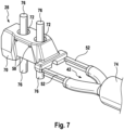
Fig. 7 eine schematische Darstellung des Lesekopfes des Drehzahlsensors derFig. 2 in einem fünften Zwischenproduktionszustand -
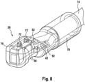
Fig. 8 eine schematische Darstellung des Lesekopfes des Drehzahlsensors derFig. 2 in einem sechsten Zwischenproduktionszustand -
Fig. 9 eine schematische Darstellung des Lesekopfes des Drehzahlsensors derFig. 2 in einem siebten Zwischenproduktionszustand, und -
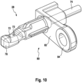
Fig. 10 eine schematische Darstellung des Lesekopfes des Drehzahlsensors derFig. 2 in einem siebten Zwischenproduktionszustand zeigen. - In den Figuren werden gleiche technische Elemente mit gleichen Bezugszeichen versehen und nur einmal beschrieben.
- Es wird auf
Fig. 1 Bezug genommen, die eine schematische Ansicht eines Fahrzeuges 2 mit einer an sich bekannten Fahrdynamikregelung zeigt. Details zu dieser Fahrdynamikregelung können beispielsweise derDE 10 2011 080 789 A1 entnommen werden. - Das Fahrzeug 2 umfasst ein Chassis 4 und vier Räder 6. Jedes Rad 6 kann über eine ortsfest am Chassis 4 befestigte Bremse 8 gegenüber dem Chassis 4 verlangsamt werden, um eine Bewegung des Fahrzeuges 2 auf einer nicht weiter dargestellten Straße zu verlangsamen.
- Dabei kann es in einer dem Fachmann bekannten Weise passieren, dass das die Räder 6 des Fahrzeugs 2 ihre Bodenhaftung verlieren und sich das Fahrzeug 2 sogar von einer beispielsweise über ein nicht weiter gezeigtes Lenkrad vorgegebenen Trajektorie durch Untersteuern oder Übersteuern wegbewegt. Dies wird durch an sich bekannte Regelkreise wie ABS (Antiblockiersystem) und ESP (elektronisches Stabilitätsprogramm) vermieden.
- In der vorliegenden Ausführung weist das Fahrzeug 2 dafür Drehzahlsensoren 10 an den Rädern 6 auf, die eine Dreh-zahl 12 der Räder 6 erfassen. Ferner weist das Fahrzeug 2 einen Inertialsensor 14 auf, der Fahrdynamidaten 16 des Fahrzeuges 2 erfasst aus denen beispielsweise eine Nickrate, eine Wankrate, eine Gierrate, eine Querbeschleunigung, eine Längsbeschleunigung und/oder eine Vertikalbeschleunigung in einer dem Fachmann an sich bekannten Weise ausgegeben werden kann.
- Basierend auf den erfassten Drehzahlen 12 und Fahrdynamikdaten 16 kann ein Regler 18 in einer dem Fachmann bekannten Weise bestimmen, ob das Fahrzeug 2 auf der Fahrbahn rutscht oder sogar von der oben genannten vorgegebenen Trajektorie abweicht und entsprechen mit einem an sich bekannten Reglerausgangssignal 20 darauf reagieren. Das Reglerausgangssignal 20 kann dann von einer Stelleinrichtung 22 verwendet werden, um mittels Stellsignalen 24 Stellglieder, wie die Bremsen 8 anzusteuern, die auf das Rutschen und die Abweichung von der vorgegebenen Trajektorie in an sich bekannter Weise reagieren.
- Der Regler 18 kann beispielsweise in eine an sich bekannte Motorsteuerung des Fahrzeuges 2 integriert sein. Auch können der Regler 18 und die Stelleinrichtung 22 als eine gemeinsame Regeleinrichtung ausgebildet und optional in die zuvor genannte Motorsteuerung integriert sein.
- Anhand des in
Fig. 1 gezeigten Raddrehzahlsensors 10 soll die vorliegende Erfindung näher verdeutlicht werden, auch wenn die vorliegende Erfindung an beliebigen Sensoren, wie Magnetfeldsensoren, Beschleunigungssensoren, Drehratensensoren, Körperschallsensoren oder Temperatursensoren umsetzbar ist. - Es wird auf
Fig. 2 Bezug genommen, die eine schematische Ansicht einer der Drehzahlsensoren 10 in der Fahrdynamikregelung derFig. 1 zeigt. - Der Drehzahlsensor 10 ist in der vorliegenden Ausführung als aktiver Drehzahlsensor ausgeführt, der ein drehfest am Rad 6 befestigtes Geberelement in Form einer Encodersscheibe 26 und eine ortsfest zum Chassis 4 befestige Sensorschaltung umfasst, die nachstehend der Einfachheit halber Lesekopf 28 genannt wird.
- Die Encoderscheibe 26 besteht in der vorliegenden Ausführung aus aneinandergereihten Magnetnordpolen 30 und Magnetsüdpolen 32, die gemeinsam ein physikalisches Feld in Form eines Gebermagnetfeldes 33 erregen. Dieses Gebermagnetfeld ist in
Fig. 3 der Übersichtlichkeit halber mit zwei gestrichelt dargestellten Feldlinien angedeutet. Dreht sich die am Rad 6 befestigte Encoderscheibe 26 mit diesem in eine Drehrichtung 34, dreht sich das Gebermagnetfeld so mit. - Der Lesekopf 28 umfasst in der vorliegenden Ausführung einen Messfühler, auch Messaufnehmer genannt, in Form eines magnetoresistiven Elementes 35. Das magnetorstriktive Element 35 ändert in Abhängigkeit der Winkellage des vom Encoderrad 26 erregten Gebermagnetfeldes 33 seinen elektrischen Widerstand. Zur Erfassung der Drehzahl 12 wird an das magnetoresisitv Element 35 ein Probesignal 39 angelegt, das in Abhängigkeit der Winkellage des Encoderrades 26 und damit des elektrischen Widerstandes magnetoresisitv Elementes 35 verändert wird. Basierend auf dieser Veränderung des Probesignals 39 wertet eine Signalauswerteschaltung 40 die Drehzahl 12 aus und gibt sie in einem Datensignal 42 an den Regler 18 aus. Diese Signalauswerteschaltung 40 kann als ASIC genannte Anwendungsspezifische integrierte Schaltung ausgebildet ebenfalls Teil des Lesekopfes 28 sein. Anstelle des magnetoresistiven Elementes 35 kann aber zur Erfassung des sich drehenden Gebermagnetfeldes 33 jeder beliebige Messaufnehmer verwendet werden, der in der Lage ist, in Abhängigkeit eines Magnetfeldes ein Signal auszugeben, so beispielsweise auch ein Hall-Element.
- Hierzu und zu weiteren Hintergrundinformationen zu aktiven Raddrehzahlsensoren wird auf den einschlägigen Stand der Technik, wie beispielsweise die
DE 101 46 949 A1 verwiesen. - Es wird auf
Fig. 3 Bezug genommen, die eine schematische Darstellung des Lesekopfes 28 für den Drehzahlsensor 10 in einem ersten Zwischenproduktionszustand zeigt. - Der Lesekopf 28 der vorliegenden Ausführung ist auf einem als sogenannter Leadframe 44 ausgeführten Schaltungsträger gehalten. Von diesem Leadframe 44 ist in
Fig. 3 nur ein Teil gezeigt. Der Leadframe 44 kann besonders bevorzugt als Endlosband ausgeführt sein, an den sich der inFig. 3 Teil gezeigte des Leadframes 44 nebeneinander und/oder übereinander anschließt. Ein Beispiel dafür ist inFig. 4 gezeigt. - Der in
Fig. 3 gezeigte Teil des Leadframes 44 umfasst einen Halterahmen 46, einen Verdrahtungsträger in Form einer Bestückinsel 48, auf der der Lesekopf 28 gehalten und verschaltet ist, zwei Tiebars 50 genannte Stege und zwei Kontaktanschlüsse 52. Dabei halten die Tiebars 50 die Kontaktanschlüsse 52 direkt und die Bestückinsel 48 am Halterahmen 46. In dem Leadframe 44 sind der Halterahmen 46, die Bestückinsel 48, die Tiebars 50 und die Kontaktanschlüsse 52 als einstückiges Stanzteil oder Stanzrahmen ausgebildet, in dem die zuvor genannten Elemente durch Stanzen aus einem elektrisch leitfähigen Blech geformt werden. - Auf der Bestückinsel 48 wird im Rahmen der vorliegenden Ausführung der Messaufnehmer in Form des magnetoresisitven Elementes 35 und die Signalauswerteschaltung 40 aufgebracht und elektrisch beispielsweise durch Löten oder Verkleben kontaktiert. Das magnetoresistive Element 35 und die Signalauswerteschaltung 40 sind dabei ferner über einen Bonddraht 54 miteinander verbunden, so dass über die Bestückinsel 48 und den Bonddraht 54 zwischen dem magnetoresisitven Element 35 und der Signalauswerteschaltung 40 das Probesignal 39 übertragen werden kann.
- Die Bestückinsel 48 ist in der vorliegenden Ausführung direkt mit einem der beiden Kontaktanschlüsse 52 verbunden, während der andere der beiden Kontaktanschlüsse 52 von der Bestückinsel 48 galvanisch getrennt und mit der Signalauswerteschaltung 40 über einen weiteren Bonddraht 54 verbunden ist. Auf diese Weise kann über die beiden Kontaktanschlüsse 56 das Datensignal 42 aus der Signalauswerteschaltung 40 ausgegeben werden. Zur Filterung von unerwünschten Fremdsignalen aus und/oder in den Lesekopf 28 kann zwischen den Kontaktanschlüssen 52 ein passives Filterbauelement 66 verschaltet werden. Je nach Art des Sensors und nach Anzahl der Kontaktanschlüsse 52 können auch mehrere passive Filterbauelemente 66 verschaltet werden.
- Der Halterahmen 46 weist im Rahmen der vorliegenden Ausführung zwei parallel zueinander verlaufende Transportsteifen 58 auf, die über Verbindungsstege 60 miteinander verbunden sind. Auf dem Transportstreifen 58 sind dabei Transportlöcher 62 ausgebildet, in die ein nicht weiter dargestelltes Transportwerkzeug eingreifen und den Leadframe 44 bewegen kann. Ferner ist auf dem Transportstreifen 58 ein Indexloch 64 ausgebildet, mittels dem die Lage des Leadframes 44 beim Transport bestimmt und damit geregelt werden kann.
- In nicht weiter dargestellter Weise kann ein Teil des Leadframes 44 als Schutzblech ausgeführt werden. Dieses Schutzblech könnte zur Wärmeisolierung des Lesekopfes 28 während des später noch zu beschreibenden Einhausungsvorgangs, als mechanische Befestigungsfläche für den Lesekopf 28 (mittels Kleber), als Druck-Widerlager für den Lesekopf 28 während des später noch zu beschreibenden Einhausungsvorgangs, als Wärmeableitschild im Betrieb und als EMV-Schild für den Lesekopf 28 verwendet werden.
- Es wird auf
Fig. 4 Bezug genommen, die einen weiteren Zwischenproduktionszustand des Lesekopfes 28 nach dem Zwischenproduktionszustand derFig. 3 zeigt. Die Leadframes 44 derFig. 3 und derFig. 4 unterscheiden sich zwar in ihrem Design, technisch sind sie jedoch funktionsgleich. Der Hauptunterschied zwischen derFig. 3 undFig. 4 ist, dass im Leadframe 44 derFig. 4 mehr Tiebars 50 vorhanden sind. - Nachdem der Herstellungszustand der
Fig. 3 erreicht und das passive Filterelement 66 verschaltet ist, können die Bestückinsel 48 mit den darauf getragenen Bauelemente 35, 40 und optional das passive Filterbauelement 66 in an sich bekannter Weise je in einer ersten Schutzmasse 68 beispielsweise aus einem duroplastischen Mold-Compound eingehaust werden. Hierzu kann beispielsweise das sogenannte Molden zum Einsatz kommen, im Rahmen dessen eine duroplastische Kunststoffmasse in einem speziellen Werkzeug um den Schaltungsträger gepresst wird. Als duroplastische Kunststoffmasse kann beispielsweise ein Epoxidharz verwendet werden. Im Allgemeinen sollte ein Material mit Eigenschaften gewählt werden, das nur einen geringen Stress auf die elektrischen Komponenten 35, 40, 66 bei gleichzeitig guter Haftung auf dem Leadframe 44 ausübt. - In der ersten Schutzmasse 68 kann auch ein nicht weiter dargestellter Magnet aufgenommen werden, der beispielsweise als Stützmagnet im Rahmen der Barberpole-Technik verwendet werden kann. Alternativ könnte der Magnet auch nach dem Einhausen in der ersten Schutzmasse 68 auf diese aufgeklebt werden.
- Ferner könnten in der ersten Schutzmasse 68 auch nach außen ragende Tragestege aufgenommen beziehungsweise eingemoldet werden. Diese könnten zur Fixierung des Lesekopfes 28 bei der weiteren Herstellung verwendet werden. Die Tragestege stützen den Lesekopf vor allem in Fällen, in denen ein großer Magnet in oder an der ersten Schutzmasse 68 gehalten ist, der zu schwerkraftbedingter Verbiegung führen könnte. Sind die Tragestege aus einem elektrisch leitfähigen Material, sollte darauf geachtet werden, dass diese keinen elektrischen Kontakt zu den elektrischen Bauteilen des Lesekopfes 28 erhalten.
- Nach dem Einhausen in der ersten Schutzmasse 68 kann die zusammen mit den Bauelementen 35, 40 eingehauste Bestückinsel 48 partiell durch Auftrennen der entsprechenden Tiebars 50 freigestanzt und so vom Halterahmen 46 getrennt werden. In gleicher Weise können auch die Kontaktanschlüsse 52 partiell freigestanzt werden. Alle anderen Elemente des Lesekopfes 28 bleiben in diesem Herstellungszustand zunächst über die Tiebars 50 mit dem Halterahmen 46 verbunden.
- Von dem so partiell freigestanzten Lesekopf 28 können nun die zusammen mit den Bauelementen 35, 40 eingehauste und freigestanzte Bestückinsel 48 sowie die freigestanzten Kontaktanschlüsse 52 in der in
Fig. 4 gezeigten Weise optional abgebogen werden. Dabei sind die zusammen mit den Bauelementen 35, 40 eingehauste, freigestanzte und abgebogene Bestückinsel 48 lila oder gepunktet und die freigestanzten und abgebogenen Kontaktanschlüsse lila/orange oder gepunktet dargestellt. - Nach dem Biegevorgang wird der noch partiell am Halterahmen 46 gehaltene Lesekopf 28 in einer Zwischenschutzmasse 70 eingehaust und im Abschluss daran vom Halterahmen 46 vollständig freigestanzt. Das Einhausen im Rahmen eines zuvor beschriebenen Mold-Prozesses erfolgen, bei dem als Material für die Zwischenschutzmasse 70 ebenfalls ein Duroplast verwendet werden kann. Die Zwischenschutzmasse 70 sorgt vor allem für einen stabilen Halt des gebogenen Lesekopfes.
- Abhängig vom Lesekopf 28 kann im vollständig im Leadframe 44 gehaltenen Zustand, im partiell freigestanzten Zustand, oder auch im freigestanzten Zustand eine Kalibrierung erfolgen. Ein Freistanzen erst unmittelbar vor der Kalibrierung bringt den Vorteil, dass die Fertigungstoleranzen sehr niedrig und auch sehr reproduzierbar sind. In besonders günstiger Weise sollte das Freistanzen des Lesekopfes 28 im Zwischenproduktionszustand der
Fig. 4 auch in zwei Schritten erfolgen. Nach dem ersten Stanzschritt sind die Versorgungs- u. Signalleitungen freigegeben und können elektrisch kontaktiert werden. In diesem Fall kann der Test oder Abgleich/Kalibrierung noch im Leadframe 44 erfolgen, was Vorteile im Handling und in der Positionierung bringt. Erst anschließend erfolgt die vollständige Freistanzung aus dem Halterahmen 46 und ggf. nicht weiter referenzierter Versorgungspins (bevorzugt Ground-Pin) . - Die Traceability des Lesekopfes 28 kann dadurch sichergestellt werden, dass zu Beginn des Fertigungsprozesses eine fortlaufende Seriennummer auf dem Leadframe 44 (z.B. ein Datamatrix-Code) aufgebracht wird. Unter dieser Seriennummer können die Produktionshistorie (Zeitstempel, Anlagennummern, Prozessmesswerte, Kalibrierwerte, Testergebnisse, etc.) und die Seriennummer des Lesekopfes 28 abgespeichert werden. Unmittelbar nach dem Freistanzen kann diese Seriennummer in einem nicht weiter dargestellten nichtflüchtigen Speicher des Lesekopfes 28 abgelegt werden. Zusätzlich kann diese Seriennummer auf der Oberfläche des Lesekopfes 28 in einem beliebigen Zwischenproduktionszustand oder Endzustand des Lesekopfes 28 aufgebracht werden. Im Falle von Reklamationen können betroffene Nummernkreise eingegrenzt und separat behandelt werden. Zusätzlich kann über eine statistische Datenauswertung die Prozess- und Material-Optimierung effektiv betrieben werden.
- Das Ergebnis nach dem vollständigen Freistanzen ist in
Fig. 5 dargestellt. An dieser Stelle sei angemerkt, dass das Einhausen in der Zwischenschutzmasse 70 entfallen kann, wenn der Lesekopf 28 nicht, wie inFig. 4 gezeigt, an seinem Leadframe 44 gebogen wird. - In die Zwischenschutzmasse 70 und/oder optional in die erste Schutzmasse 68 des Lesekopf 28 in dem Herstellungszustand der
Fig. 4 und5 werden inFig. 6 gezeigte Ausnehmungen 72 oder auch Mulden eingeformt, auf die an späterer Stelle näher eingegangen wird. Die Ausnehmungen 72 können im Rahmen des zuvor genannten Urformprozesses ausgebildet werden. Selbstverständlich können die Ausnehmungen 72 prinzipiell aber auch nachträglich eingeformt werden. Die Ausnehmungen 72 könnten prinzipiell auch im Leadframe 44 beispielsweise als Ösen ausgebildet werden. - Ferner können weitere Konturen für ein sicheres Handling bei der Herstellung vorgesehen werden, wie beispielsweise plane Flächen als Angriffsmöglichkeit für eine Saugdüse oder Konturen für einen Greifer.
- Ferner können seitlich am Lesekopf 28 im Zwischenproduktionszustand der
Fig. 5 oder6 Schürzen geformt werden, die eine seitliche Justage, einen Hitzeschutz, einen mechanischen Schutz gegen den Fließdruck der Zwischenschutzmasse 70 und/oder der ersten Schutzmasse 68 und im Falle von eventuell eingebrachten Schlitzen eine Fixierung des Lesekopfes 28 bewirken. - Zur Stabilisierung eventueller Schweißbedingungen kann eine Sicke geprägt werden. Bevorzugt in den Träger-Leadframe. Die Sicke kann die Form einer Rundkuppel oder eines Längssteges aufweisen.
- An die Kontaktanschlüsse 52 wird, wie in
Fig. 6 dargestellt im Anschluss an das Einhausen mit der Zwischenschutzmasse 70 ein Signalübertragungselement in Form eines Datenkabels 74 angeschlossen. Dies kann in beliebiger Weise, wie Crimpen, Schweißen, Löten, Splicen, Kleben oder dergleichen erfolgen. - Wurde die Zwischenschutzmasse 70 und/oder die erste Schutzmasse 68 gemeldet, kann sich bei Toleranzschwankungen des Materials des Leadframes 44 an einer Dichtkante der Schalen des Mold-Werkzeuges ein sogenannter Flash bilden. Dieser Flash kann mechanisch durch Bürsten oder durch einen Luft-Jet-Strom oder mittels eines Lasers entfernt werden.
- Im Anschluss daran wird der Lesekopf 28 in dem Zwischenproduktionszustand der
Fig. 6 in einer zweiten Schutzmasse 78 eingehaust. Diese zweite Schutzmasse 78 kann beispielsweise ein Thermoplast sein. Das Einhausen in der zweiten Schutzmasse kann dabei im Rahmen eines Urformprozesses, wie beispielsweise Spritzgießen erfolgen. Hierbei könnte als Material ein Thermoplast wie ein LCP genanntes Flüssigkristallpolymer, ein PPS genanntes Polyphenylensulfid, PA genanntes Polyamid oder PBT genanntes Polybutylenterephthalat eingesetzt werden. Bei der Wahl des Materials stehen ein niedriger Temperaturausdehnungskoeffizient, chemische Beständigkeit, mechanische Festigkeit und Dichtigkeit im Vordergrund. Prinzipiell könnte das Einhausen aber auch im Rahmen eines Moldvorgangs erfolgen und als Material für die zweite Schutzmasse 78 wieder ein Duroplast gewählt werden. - Zum Einhausen in der zweiten Schutzmasse werden, wie in
Fig. 7 gezeigt, in die Ausnehmungen 72 Tragestifte 76 eingesetzt, an denen der Lesekopf 28 beim Einhüllen mit der zweiten Schutzmasse 78 gehalten wird. Durch die Tragestifte 76 wird der Sensorkopf 28 beim Einhausen mit der zweiten Schutzmasse 78 nicht nur gestützt sondern auch in einer bestimmten Richtung ausgerichtet. Im Anschluss an das Einhausen werden die Tragestifte 76 wieder entfernt, so dass die Ausnehmungen 72 nicht nur in der Zwischenschutzmasse 70 beziehungsweise ersten Schutzmasse 68 sondern auch in der zweiten Schutzmasse 78 zurückbleiben. Eventuell können zwischen der ersten Schutzmasse 68 respektive der Zwischenschutzmasse 70 und der zweiten Schutzmasse 78 spaltverlängernde Geometrien, wie eine unebene Oberfläche der ersten Schutzmasse 68 respektive der Zwischenschutzmasse 70 ausgebildet werden, um den Weg für in die Ausnehmungen 72 und damit zwischen den aneinander angrenzenden Massen 68, 70, 78 eindringende Feuchtigkeit zu verlängern. - In dem Zwischenproduktionszustand der
Fig. 8 ist der Sensorkopf 28 bereits elektrisch voll funktionsfähig und könnte an eine übergeordnete elektronische Einrichtung, wie beispielsweise den Regler 18 angeschlossen werden. Um den Sensorkopf 28 jedoch in dem Fahrzeug 2 zu verbauen, muss noch eine mechanische Schnittstelle geschaffen werden, um den Sensor 2 am Chassis 4 zu befestigen. Diese mechanische Schnittstelle ist jedoch vom Bauraum des Fahrzeuges 2 abhängig. Der Sensorkopf 28 in dem Zwischenproduktionszustand derFig. 8 kann aus elektrischer Hinsicht prinzipiell in jedem beliebigen Fahrzeug 2 eingesetzt werden und soll daher als sogenanntes Neutralteil bezeichnet werden. - Dieses Neutralteil kann in beliebiger Weise transportiert, gelagert oder vertrieben werden. Im Anschluss lässt es sich in einfacher Weise an den Bauraum des Fahrzeuges 2 durch Hinzufügen einer in
Fig. 9 beispielhaft dargestellten mechanischen Schnittstelle 80 an den Bauraum des Fahrzeuges 2 angepasst werden. - Wie in
Fig. 9 gezeigt, wird hierzu an das Neutralteil derFig. 8 eine dritte Schutzmasse 82 durch ein Urformverfahren, wie beispielsweise ein Spritzgussverfahren angeformt. In diese dritte Schutzmasse 82 wird eine Hülse 84 eingeformt, durch die später ein Befestigungsmittel, wie beispielsweise eine Schraube zum Befestigen des Lesekopfes 28 am Fahrzeug 2 geführt werden kann. Ferner kann um die angeformte dritte Schutzmasse 82 eine Schelle 86 gelegt werden, um die den mechanischen Halt der dritten Schutzmasse 82 am Neutralteil derFig. 8 erhöht. - In
Fig. 10 ist eine alternative Möglichkeit gezeigt, wie die mechanische Schnittstelle 80 ausgebildet werden kann.
Claims (2)
- Verfahren zum Herstellen eines Sensors (28) mit einem Schaltungsträger (44), der eine eine Sensorschaltung (35, 40) zur Ausgabe eines von einem physikalischen Geberfeld (33) abhängigen Sensorsignals (42) tragende Bestückinsel (48) und eine mit der Bestückinsel (48) elektrisch verbundene Schnittstelle (52) zum Senden des Sensorsignals (42) an eine übergeordnete Signalverarbeitungseinrichtung (18) aufweist, gekennzeichnet durch:- Einhüllen eines die Bestückinsel (48) und die Sensorschaltung (35, 40) enthaltenen Teils des Schaltungsträgers (44) in einer ersten Schutzmasse (68),- Anschließen eines Signalübertragungselementes (74) an die Schnittstelle (52), und- Einhüllen wenigstens eines Teils der ersten Schutzmasse (68) und der Schnittstelle (52) mit wenigstens einem Teil des daran angeschlossenen Signalübertragungselementes (74) in einer zweiten Schutzmasse (78), wobei das Einhüllen mittels der ersten Schutzmasse als Molden durchgeführt wird, im Rahmen dessen eine duroplastische Kunststoffmasse, als die erste Schutzmasse, in einem speziellen Werkzeug um den Schaltungsträger gepresst wird, wobei das Signalübertragungselement (74) ein Kabel ist,- Einhüllen wenigstens eines Teils der zweiten Schutzmasse (78) in einer dritten Schutzmasse (82), wobei das Ausbilden der dritten Schutzmasse (82) mit einem Befestigungsabschnitt (80) zum Befestigen des Sensors (28) an einem Sensorträger (4) ausgeführt wird, wobei der Befestigungsabschnitt (80) eine Hülse (84) umfasst, die radial von der dritten Schutzmasse (82) eingehüllt wird.
- Sensor (28), mit einem Schaltungsträger (44), wobei der Schaltungsträger (44)eine Sensorschaltung (35, 40) zur Ausgabe eines von einem physikalischen Geberfeld (33) abhängigen Sensorsignals (42) tragende Bestückinsel (48) und eine mit der Bestückinsel (48) elektrisch verbundene Schnittstelle (52) zum Senden des Sensorsignals (42) an eine übergeordnete Signalverarbeitungseinrichtung (18) aufweist, dadurch gekennzeichnet, dass der Sensor außerdemeine erste Schutzmasse (68) aufweist, welche einen die Bestückinsel (48) und die Sensorschaltung (35, 40) enthaltenen Teils des Schaltungsträgers (44) einhüllt,wobeiein Signalübertragungselement (74) an die Schnittstelle (52) angeschlossen ist, undwobei der Sensor eine zweite Schutzmasse (78) aufweist, welche wenigstens einen Teil der ersten Schutzmasse (68) und der Schnittstelle (52) mit wenigstens einem Teil des daran angeschlossenen Signalübertragungselementes (74) einhüllt, wobei das Einhüllen mittels der ersten Schutzmasse als Molden ausgeführt ist, im Rahmen dessen eine duroplastische Kunststoffmasse, als die erste Schutzmasse, in einem speziellen Werkzeug um den Schaltungsträger gepresst ist, wobei das Signalübertragungselement (74) ein Kabel ist,wobei der Sensor eine dritte Schutzmasse (82) mit einem Befestigungsabschnitt (80) zum Befestigen des Sensors (28) an einem Sensorträger (4) aufweist, wobei der Befestigungsabschnitt (80) eine Hülse (84) umfasst, die radial von der dritten Schutzmasse (82) eingehüllt ist, wobei die dritte Schutzmasse (82) wenigstens einen Teil der zweiten Schutzmasse (78) einhüllt.
Applications Claiming Priority (1)
| Application Number | Priority Date | Filing Date | Title |
|---|---|---|---|
| PCT/EP2015/066160 WO2016005608A1 (de) | 2014-07-11 | 2015-07-15 | Neutralteil für einen kundenspezifisch adaptierbaren sensor |
Publications (2)
| Publication Number | Publication Date |
|---|---|
| EP3167249A1 EP3167249A1 (de) | 2017-05-17 |
| EP3167249B1 true EP3167249B1 (de) | 2023-03-15 |
Family
ID=59409779
Family Applications (1)
| Application Number | Title | Priority Date | Filing Date |
|---|---|---|---|
| EP15788333.1A Active EP3167249B1 (de) | 2015-07-15 | 2015-07-15 | Neutralteil für einen kundenspezifisch adaptierbaren sensor |
Country Status (2)
| Country | Link |
|---|---|
| EP (1) | EP3167249B1 (de) |
| WO (1) | WO2016005608A1 (de) |
Citations (2)
| Publication number | Priority date | Publication date | Assignee | Title |
|---|---|---|---|---|
| DE19504608A1 (de) * | 1995-02-11 | 1996-08-14 | Balluff Gebhard Feinmech | Positionssensor und Verfahren zur Herstellung desselben |
| DE102013202212A1 (de) * | 2012-02-10 | 2013-08-14 | Continental Teves Ag & Co. Ohg | Zweistufig gemoldeter Sensor |
Family Cites Families (7)
| Publication number | Priority date | Publication date | Assignee | Title |
|---|---|---|---|---|
| US4847557A (en) * | 1987-03-18 | 1989-07-11 | Sumitomo Electric Industries, Ltd. | Hermetically sealed magnetic sensor |
| JP3671563B2 (ja) * | 1996-12-09 | 2005-07-13 | 株式会社デンソー | モールドicをケースに固定した構造の半導体装置 |
| DE10146949A1 (de) | 2000-11-22 | 2002-06-06 | Continental Teves Ag & Co Ohg | Aktiver Magnetsensor für elektronische Bremssysteme |
| JP2004198240A (ja) * | 2002-12-18 | 2004-07-15 | Denso Corp | センサ装置 |
| DE102008064046A1 (de) | 2008-10-02 | 2010-04-08 | Continental Teves Ag & Co. Ohg | Verfahren zur Herstellung eines Geschwindigkeits-Sensorelementes |
| DE102011080789B4 (de) | 2010-08-10 | 2022-11-10 | Continental Automotive Technologies GmbH | Verfahren und System zur Regelung der Fahrstabilität |
| JP5573826B2 (ja) * | 2011-12-16 | 2014-08-20 | 株式会社デンソー | 回転検出装置およびその製造方法 |
-
2015
- 2015-07-15 WO PCT/EP2015/066160 patent/WO2016005608A1/de not_active Ceased
- 2015-07-15 EP EP15788333.1A patent/EP3167249B1/de active Active
Patent Citations (2)
| Publication number | Priority date | Publication date | Assignee | Title |
|---|---|---|---|---|
| DE19504608A1 (de) * | 1995-02-11 | 1996-08-14 | Balluff Gebhard Feinmech | Positionssensor und Verfahren zur Herstellung desselben |
| DE102013202212A1 (de) * | 2012-02-10 | 2013-08-14 | Continental Teves Ag & Co. Ohg | Zweistufig gemoldeter Sensor |
Also Published As
| Publication number | Publication date |
|---|---|
| EP3167249A1 (de) | 2017-05-17 |
| WO2016005608A1 (de) | 2016-01-14 |
Similar Documents
| Publication | Publication Date | Title |
|---|---|---|
| EP3074730B1 (de) | Sensorherstellung durch halten des zwischenspritzlings | |
| DE102013214915A1 (de) | Verdrahtungseinrichtung zum Verdrahten einer elektronischen Vorrichtung | |
| EP0889774A1 (de) | Kunststoffsensor und verfahren zu dessen herstellung | |
| DE102008018199A1 (de) | Elektrische Baugruppe mit einem Stanzgitter, elektrischen Bauelementen und einer Füllmasse | |
| EP2223125A2 (de) | Magnetfeld-sensorelement | |
| EP2936553A1 (de) | Verfahren zum herstellen einer elektronischen baugruppe | |
| DE102013217888B4 (de) | Elektronische Vorrichtung und Verfahren zur Herstellung einer elektronischen Vorrichtung | |
| EP2812657A1 (de) | Zweistufig gemoldeter sensor | |
| EP0649719B1 (de) | Verfahren zur Herstellung von Chipkarten mittels Spritzgiessen | |
| WO2016005609A2 (de) | Kundenspezifischer sensor hergestellt durch dreifach-molden | |
| EP2936515B1 (de) | Verfahren zum herstellen eines messaufnehmers | |
| EP3167249B1 (de) | Neutralteil für einen kundenspezifisch adaptierbaren sensor | |
| EP3471518B1 (de) | Verfahren zur herstellung von optoelektronischen sensoren, insbesondere von miniatursensoren | |
| DE102014213591A1 (de) | Neutralteil für einen kundenspezifisch adaptierbaren Sensor | |
| WO2015078959A1 (de) | Verfahren zum herstellen einer elektronischen baugruppe | |
| DE102015206299B4 (de) | Über Leiterplatte auf Leadframe verschaltete Sensorschaltung | |
| EP3074729A1 (de) | Werkzeug zum urformen eines gehäuses für einen sensor | |
| DE102014213590A1 (de) | Kundenspezifischer Adapter für Standardsensor | |
| DE102014210523A1 (de) | Spannungsarmes Verkleben von Sensorchips | |
| DE10155535A1 (de) | Radsensor mit einem Kunststoffgehäuse und Verfahren zu dessen Herstellung | |
| DE102015225071A1 (de) | Verfahren zur Fertigung eines Raddrehzahlsensors | |
| DE102015207533A1 (de) | Schirmung als Silikonvergusshalter | |
| WO2019115066A1 (de) | Sensorbaugruppe und verfahren zur herstellung einer sensorbaugruppe | |
| DE102014213231A1 (de) | Sensorunterseitig verschaltete passive Bauelemente |
Legal Events
| Date | Code | Title | Description |
|---|---|---|---|
| STAA | Information on the status of an ep patent application or granted ep patent |
Free format text: STATUS: THE INTERNATIONAL PUBLICATION HAS BEEN MADE |
|
| PUAI | Public reference made under article 153(3) epc to a published international application that has entered the european phase |
Free format text: ORIGINAL CODE: 0009012 |
|
| STAA | Information on the status of an ep patent application or granted ep patent |
Free format text: STATUS: REQUEST FOR EXAMINATION WAS MADE |
|
| 17P | Request for examination filed |
Effective date: 20170213 |
|
| AK | Designated contracting states |
Kind code of ref document: A1 Designated state(s): AL AT BE BG CH CY CZ DE DK EE ES FI FR GB GR HR HU IE IS IT LI LT LU LV MC MK MT NL NO PL PT RO RS SE SI SK SM TR |
|
| AX | Request for extension of the european patent |
Extension state: BA ME |
|
| RAP1 | Party data changed (applicant data changed or rights of an application transferred) |
Owner name: CONTINENTAL TEVES AG & CO. OHG |
|
| DAV | Request for validation of the european patent (deleted) | ||
| DAX | Request for extension of the european patent (deleted) | ||
| STAA | Information on the status of an ep patent application or granted ep patent |
Free format text: STATUS: EXAMINATION IS IN PROGRESS |
|
| 17Q | First examination report despatched |
Effective date: 20200320 |
|
| RIC1 | Information provided on ipc code assigned before grant |
Ipc: G01D 11/24 20060101AFI20210127BHEP |
|
| RAP1 | Party data changed (applicant data changed or rights of an application transferred) |
Owner name: CONTINENTAL AUTOMOTIVE TECHNOLOGIES GMBH |
|
| GRAP | Despatch of communication of intention to grant a patent |
Free format text: ORIGINAL CODE: EPIDOSNIGR1 |
|
| STAA | Information on the status of an ep patent application or granted ep patent |
Free format text: STATUS: GRANT OF PATENT IS INTENDED |
|
| RIC1 | Information provided on ipc code assigned before grant |
Ipc: G01D 11/24 20060101ALI20221102BHEP Ipc: G01D 5/245 20060101AFI20221102BHEP |
|
| INTG | Intention to grant announced |
Effective date: 20221123 |
|
| GRAS | Grant fee paid |
Free format text: ORIGINAL CODE: EPIDOSNIGR3 |
|
| GRAA | (expected) grant |
Free format text: ORIGINAL CODE: 0009210 |
|
| STAA | Information on the status of an ep patent application or granted ep patent |
Free format text: STATUS: THE PATENT HAS BEEN GRANTED |
|
| AK | Designated contracting states |
Kind code of ref document: B1 Designated state(s): AL AT BE BG CH CY CZ DE DK EE ES FI FR GB GR HR HU IE IS IT LI LT LU LV MC MK MT NL NO PL PT RO RS SE SI SK SM TR |
|
| REG | Reference to a national code |
Ref country code: CH Ref legal event code: EP Ref country code: GB Ref legal event code: FG4D Free format text: NOT ENGLISH |
|
| REG | Reference to a national code |
Ref country code: DE Ref legal event code: R096 Ref document number: 502015016289 Country of ref document: DE |
|
| REG | Reference to a national code |
Ref country code: IE Ref legal event code: FG4D Free format text: LANGUAGE OF EP DOCUMENT: GERMAN |
|
| REG | Reference to a national code |
Ref country code: AT Ref legal event code: REF Ref document number: 1554248 Country of ref document: AT Kind code of ref document: T Effective date: 20230415 |
|
| REG | Reference to a national code |
Ref country code: LT Ref legal event code: MG9D |
|
| REG | Reference to a national code |
Ref country code: NL Ref legal event code: MP Effective date: 20230315 |
|
| PG25 | Lapsed in a contracting state [announced via postgrant information from national office to epo] |
Ref country code: RS Free format text: LAPSE BECAUSE OF FAILURE TO SUBMIT A TRANSLATION OF THE DESCRIPTION OR TO PAY THE FEE WITHIN THE PRESCRIBED TIME-LIMIT Effective date: 20230315 Ref country code: NO Free format text: LAPSE BECAUSE OF FAILURE TO SUBMIT A TRANSLATION OF THE DESCRIPTION OR TO PAY THE FEE WITHIN THE PRESCRIBED TIME-LIMIT Effective date: 20230615 Ref country code: LV Free format text: LAPSE BECAUSE OF FAILURE TO SUBMIT A TRANSLATION OF THE DESCRIPTION OR TO PAY THE FEE WITHIN THE PRESCRIBED TIME-LIMIT Effective date: 20230315 Ref country code: LT Free format text: LAPSE BECAUSE OF FAILURE TO SUBMIT A TRANSLATION OF THE DESCRIPTION OR TO PAY THE FEE WITHIN THE PRESCRIBED TIME-LIMIT Effective date: 20230315 Ref country code: HR Free format text: LAPSE BECAUSE OF FAILURE TO SUBMIT A TRANSLATION OF THE DESCRIPTION OR TO PAY THE FEE WITHIN THE PRESCRIBED TIME-LIMIT Effective date: 20230315 |
|
| PG25 | Lapsed in a contracting state [announced via postgrant information from national office to epo] |
Ref country code: SE Free format text: LAPSE BECAUSE OF FAILURE TO SUBMIT A TRANSLATION OF THE DESCRIPTION OR TO PAY THE FEE WITHIN THE PRESCRIBED TIME-LIMIT Effective date: 20230315 Ref country code: NL Free format text: LAPSE BECAUSE OF FAILURE TO SUBMIT A TRANSLATION OF THE DESCRIPTION OR TO PAY THE FEE WITHIN THE PRESCRIBED TIME-LIMIT Effective date: 20230315 Ref country code: GR Free format text: LAPSE BECAUSE OF FAILURE TO SUBMIT A TRANSLATION OF THE DESCRIPTION OR TO PAY THE FEE WITHIN THE PRESCRIBED TIME-LIMIT Effective date: 20230616 Ref country code: FI Free format text: LAPSE BECAUSE OF FAILURE TO SUBMIT A TRANSLATION OF THE DESCRIPTION OR TO PAY THE FEE WITHIN THE PRESCRIBED TIME-LIMIT Effective date: 20230315 |
|
| PG25 | Lapsed in a contracting state [announced via postgrant information from national office to epo] |
Ref country code: SM Free format text: LAPSE BECAUSE OF FAILURE TO SUBMIT A TRANSLATION OF THE DESCRIPTION OR TO PAY THE FEE WITHIN THE PRESCRIBED TIME-LIMIT Effective date: 20230315 Ref country code: RO Free format text: LAPSE BECAUSE OF FAILURE TO SUBMIT A TRANSLATION OF THE DESCRIPTION OR TO PAY THE FEE WITHIN THE PRESCRIBED TIME-LIMIT Effective date: 20230315 Ref country code: PT Free format text: LAPSE BECAUSE OF FAILURE TO SUBMIT A TRANSLATION OF THE DESCRIPTION OR TO PAY THE FEE WITHIN THE PRESCRIBED TIME-LIMIT Effective date: 20230717 Ref country code: ES Free format text: LAPSE BECAUSE OF FAILURE TO SUBMIT A TRANSLATION OF THE DESCRIPTION OR TO PAY THE FEE WITHIN THE PRESCRIBED TIME-LIMIT Effective date: 20230315 Ref country code: EE Free format text: LAPSE BECAUSE OF FAILURE TO SUBMIT A TRANSLATION OF THE DESCRIPTION OR TO PAY THE FEE WITHIN THE PRESCRIBED TIME-LIMIT Effective date: 20230315 Ref country code: CZ Free format text: LAPSE BECAUSE OF FAILURE TO SUBMIT A TRANSLATION OF THE DESCRIPTION OR TO PAY THE FEE WITHIN THE PRESCRIBED TIME-LIMIT Effective date: 20230315 |
|
| PG25 | Lapsed in a contracting state [announced via postgrant information from national office to epo] |
Ref country code: SK Free format text: LAPSE BECAUSE OF FAILURE TO SUBMIT A TRANSLATION OF THE DESCRIPTION OR TO PAY THE FEE WITHIN THE PRESCRIBED TIME-LIMIT Effective date: 20230315 Ref country code: PL Free format text: LAPSE BECAUSE OF FAILURE TO SUBMIT A TRANSLATION OF THE DESCRIPTION OR TO PAY THE FEE WITHIN THE PRESCRIBED TIME-LIMIT Effective date: 20230315 Ref country code: IS Free format text: LAPSE BECAUSE OF FAILURE TO SUBMIT A TRANSLATION OF THE DESCRIPTION OR TO PAY THE FEE WITHIN THE PRESCRIBED TIME-LIMIT Effective date: 20230715 |
|
| REG | Reference to a national code |
Ref country code: DE Ref legal event code: R097 Ref document number: 502015016289 Country of ref document: DE |
|
| PLBE | No opposition filed within time limit |
Free format text: ORIGINAL CODE: 0009261 |
|
| STAA | Information on the status of an ep patent application or granted ep patent |
Free format text: STATUS: NO OPPOSITION FILED WITHIN TIME LIMIT |
|
| PG25 | Lapsed in a contracting state [announced via postgrant information from national office to epo] |
Ref country code: SI Free format text: LAPSE BECAUSE OF FAILURE TO SUBMIT A TRANSLATION OF THE DESCRIPTION OR TO PAY THE FEE WITHIN THE PRESCRIBED TIME-LIMIT Effective date: 20230315 Ref country code: DK Free format text: LAPSE BECAUSE OF FAILURE TO SUBMIT A TRANSLATION OF THE DESCRIPTION OR TO PAY THE FEE WITHIN THE PRESCRIBED TIME-LIMIT Effective date: 20230315 |
|
| 26N | No opposition filed |
Effective date: 20231218 |
|
| REG | Reference to a national code |
Ref country code: DE Ref legal event code: R081 Ref document number: 502015016289 Country of ref document: DE Owner name: CONTINENTAL AUTOMOTIVE TECHNOLOGIES GMBH, DE Free format text: FORMER OWNER: CONTINENTAL AUTOMOTIVE TECHNOLOGIES GMBH, 30165 HANNOVER, DE Ref country code: DE Ref legal event code: R081 Ref document number: 502015016289 Country of ref document: DE Owner name: AUMOVIO GERMANY GMBH, DE Free format text: FORMER OWNER: CONTINENTAL AUTOMOTIVE TECHNOLOGIES GMBH, 30165 HANNOVER, DE |
|
| PG25 | Lapsed in a contracting state [announced via postgrant information from national office to epo] |
Ref country code: MC Free format text: LAPSE BECAUSE OF FAILURE TO SUBMIT A TRANSLATION OF THE DESCRIPTION OR TO PAY THE FEE WITHIN THE PRESCRIBED TIME-LIMIT Effective date: 20230315 |
|
| PG25 | Lapsed in a contracting state [announced via postgrant information from national office to epo] |
Ref country code: MC Free format text: LAPSE BECAUSE OF FAILURE TO SUBMIT A TRANSLATION OF THE DESCRIPTION OR TO PAY THE FEE WITHIN THE PRESCRIBED TIME-LIMIT Effective date: 20230315 |
|
| REG | Reference to a national code |
Ref country code: CH Ref legal event code: PL |
|
| REG | Reference to a national code |
Ref country code: BE Ref legal event code: MM Effective date: 20230731 |
|
| PG25 | Lapsed in a contracting state [announced via postgrant information from national office to epo] |
Ref country code: LU Free format text: LAPSE BECAUSE OF NON-PAYMENT OF DUE FEES Effective date: 20230715 |
|
| PG25 | Lapsed in a contracting state [announced via postgrant information from national office to epo] |
Ref country code: LU Free format text: LAPSE BECAUSE OF NON-PAYMENT OF DUE FEES Effective date: 20230715 |
|
| REG | Reference to a national code |
Ref country code: IE Ref legal event code: MM4A |
|
| PG25 | Lapsed in a contracting state [announced via postgrant information from national office to epo] |
Ref country code: CH Free format text: LAPSE BECAUSE OF NON-PAYMENT OF DUE FEES Effective date: 20230731 |
|
| PG25 | Lapsed in a contracting state [announced via postgrant information from national office to epo] |
Ref country code: IT Free format text: LAPSE BECAUSE OF FAILURE TO SUBMIT A TRANSLATION OF THE DESCRIPTION OR TO PAY THE FEE WITHIN THE PRESCRIBED TIME-LIMIT Effective date: 20230315 Ref country code: BE Free format text: LAPSE BECAUSE OF NON-PAYMENT OF DUE FEES Effective date: 20230731 |
|
| PG25 | Lapsed in a contracting state [announced via postgrant information from national office to epo] |
Ref country code: IE Free format text: LAPSE BECAUSE OF NON-PAYMENT OF DUE FEES Effective date: 20230715 |
|
| PG25 | Lapsed in a contracting state [announced via postgrant information from national office to epo] |
Ref country code: IE Free format text: LAPSE BECAUSE OF NON-PAYMENT OF DUE FEES Effective date: 20230715 |
|
| REG | Reference to a national code |
Ref country code: AT Ref legal event code: MM01 Ref document number: 1554248 Country of ref document: AT Kind code of ref document: T Effective date: 20230715 |
|
| PG25 | Lapsed in a contracting state [announced via postgrant information from national office to epo] |
Ref country code: AT Free format text: LAPSE BECAUSE OF NON-PAYMENT OF DUE FEES Effective date: 20230715 |
|
| PG25 | Lapsed in a contracting state [announced via postgrant information from national office to epo] |
Ref country code: AT Free format text: LAPSE BECAUSE OF NON-PAYMENT OF DUE FEES Effective date: 20230715 |
|
| PG25 | Lapsed in a contracting state [announced via postgrant information from national office to epo] |
Ref country code: BG Free format text: LAPSE BECAUSE OF FAILURE TO SUBMIT A TRANSLATION OF THE DESCRIPTION OR TO PAY THE FEE WITHIN THE PRESCRIBED TIME-LIMIT Effective date: 20230315 |
|
| PG25 | Lapsed in a contracting state [announced via postgrant information from national office to epo] |
Ref country code: BG Free format text: LAPSE BECAUSE OF FAILURE TO SUBMIT A TRANSLATION OF THE DESCRIPTION OR TO PAY THE FEE WITHIN THE PRESCRIBED TIME-LIMIT Effective date: 20230315 |
|
| PG25 | Lapsed in a contracting state [announced via postgrant information from national office to epo] |
Ref country code: CY Free format text: LAPSE BECAUSE OF FAILURE TO SUBMIT A TRANSLATION OF THE DESCRIPTION OR TO PAY THE FEE WITHIN THE PRESCRIBED TIME-LIMIT; INVALID AB INITIO Effective date: 20150715 |
|
| PG25 | Lapsed in a contracting state [announced via postgrant information from national office to epo] |
Ref country code: HU Free format text: LAPSE BECAUSE OF FAILURE TO SUBMIT A TRANSLATION OF THE DESCRIPTION OR TO PAY THE FEE WITHIN THE PRESCRIBED TIME-LIMIT; INVALID AB INITIO Effective date: 20150715 |
|
| PGFP | Annual fee paid to national office [announced via postgrant information from national office to epo] |
Ref country code: DE Payment date: 20250731 Year of fee payment: 11 |
|
| PGFP | Annual fee paid to national office [announced via postgrant information from national office to epo] |
Ref country code: GB Payment date: 20250722 Year of fee payment: 11 |
|
| PGFP | Annual fee paid to national office [announced via postgrant information from national office to epo] |
Ref country code: FR Payment date: 20250725 Year of fee payment: 11 |
|
| PG25 | Lapsed in a contracting state [announced via postgrant information from national office to epo] |
Ref country code: TR Free format text: LAPSE BECAUSE OF FAILURE TO SUBMIT A TRANSLATION OF THE DESCRIPTION OR TO PAY THE FEE WITHIN THE PRESCRIBED TIME-LIMIT Effective date: 20230315 |
|
| REG | Reference to a national code |
Ref country code: DE Ref legal event code: R081 Ref document number: 502015016289 Country of ref document: DE Owner name: AUMOVIO GERMANY GMBH, DE Free format text: FORMER OWNER: CONTINENTAL AUTOMOTIVE TECHNOLOGIES GMBH, 30175 HANNOVER, DE |