EP3168657B1 - Optique auxiliaire et système d'optique auxiliaire comprenant plusieurs optiques auxiliaires - Google Patents
Optique auxiliaire et système d'optique auxiliaire comprenant plusieurs optiques auxiliaires Download PDFInfo
- Publication number
- EP3168657B1 EP3168657B1 EP16198483.6A EP16198483A EP3168657B1 EP 3168657 B1 EP3168657 B1 EP 3168657B1 EP 16198483 A EP16198483 A EP 16198483A EP 3168657 B1 EP3168657 B1 EP 3168657B1
- Authority
- EP
- European Patent Office
- Prior art keywords
- light
- attachment
- optical
- region
- focal point
- Prior art date
- Legal status (The legal status is an assumption and is not a legal conclusion. Google has not performed a legal analysis and makes no representation as to the accuracy of the status listed.)
- Active
Links
Images


Classifications
-
- G—PHYSICS
- G02—OPTICS
- G02B—OPTICAL ELEMENTS, SYSTEMS OR APPARATUS
- G02B19/00—Condensers, e.g. light collectors or similar non-imaging optics
- G02B19/0004—Condensers, e.g. light collectors or similar non-imaging optics characterised by the optical means employed
- G02B19/0028—Condensers, e.g. light collectors or similar non-imaging optics characterised by the optical means employed refractive and reflective surfaces, e.g. non-imaging catadioptric systems
-
- F—MECHANICAL ENGINEERING; LIGHTING; HEATING; WEAPONS; BLASTING
- F21—LIGHTING
- F21S—NON-PORTABLE LIGHTING DEVICES; SYSTEMS THEREOF; VEHICLE LIGHTING DEVICES SPECIALLY ADAPTED FOR VEHICLE EXTERIORS
- F21S43/00—Signalling devices specially adapted for vehicle exteriors, e.g. brake lamps, direction indicator lights or reversing lights
- F21S43/20—Signalling devices specially adapted for vehicle exteriors, e.g. brake lamps, direction indicator lights or reversing lights characterised by refractors, transparent cover plates, light guides or filters
- F21S43/235—Light guides
- F21S43/236—Light guides characterised by the shape of the light guide
- F21S43/239—Light guides characterised by the shape of the light guide plate-shaped
-
- F—MECHANICAL ENGINEERING; LIGHTING; HEATING; WEAPONS; BLASTING
- F21—LIGHTING
- F21S—NON-PORTABLE LIGHTING DEVICES; SYSTEMS THEREOF; VEHICLE LIGHTING DEVICES SPECIALLY ADAPTED FOR VEHICLE EXTERIORS
- F21S43/00—Signalling devices specially adapted for vehicle exteriors, e.g. brake lamps, direction indicator lights or reversing lights
- F21S43/20—Signalling devices specially adapted for vehicle exteriors, e.g. brake lamps, direction indicator lights or reversing lights characterised by refractors, transparent cover plates, light guides or filters
- F21S43/235—Light guides
- F21S43/236—Light guides characterised by the shape of the light guide
- F21S43/241—Light guides characterised by the shape of the light guide of complex shape
-
- F—MECHANICAL ENGINEERING; LIGHTING; HEATING; WEAPONS; BLASTING
- F21—LIGHTING
- F21S—NON-PORTABLE LIGHTING DEVICES; SYSTEMS THEREOF; VEHICLE LIGHTING DEVICES SPECIALLY ADAPTED FOR VEHICLE EXTERIORS
- F21S43/00—Signalling devices specially adapted for vehicle exteriors, e.g. brake lamps, direction indicator lights or reversing lights
- F21S43/20—Signalling devices specially adapted for vehicle exteriors, e.g. brake lamps, direction indicator lights or reversing lights characterised by refractors, transparent cover plates, light guides or filters
- F21S43/235—Light guides
- F21S43/242—Light guides characterised by the emission area
- F21S43/243—Light guides characterised by the emission area emitting light from one or more of its extremities
-
- F—MECHANICAL ENGINEERING; LIGHTING; HEATING; WEAPONS; BLASTING
- F21—LIGHTING
- F21S—NON-PORTABLE LIGHTING DEVICES; SYSTEMS THEREOF; VEHICLE LIGHTING DEVICES SPECIALLY ADAPTED FOR VEHICLE EXTERIORS
- F21S43/00—Signalling devices specially adapted for vehicle exteriors, e.g. brake lamps, direction indicator lights or reversing lights
- F21S43/20—Signalling devices specially adapted for vehicle exteriors, e.g. brake lamps, direction indicator lights or reversing lights characterised by refractors, transparent cover plates, light guides or filters
- F21S43/235—Light guides
- F21S43/247—Light guides with a single light source being coupled into the light guide
-
- F—MECHANICAL ENGINEERING; LIGHTING; HEATING; WEAPONS; BLASTING
- F21—LIGHTING
- F21S—NON-PORTABLE LIGHTING DEVICES; SYSTEMS THEREOF; VEHICLE LIGHTING DEVICES SPECIALLY ADAPTED FOR VEHICLE EXTERIORS
- F21S43/00—Signalling devices specially adapted for vehicle exteriors, e.g. brake lamps, direction indicator lights or reversing lights
- F21S43/30—Signalling devices specially adapted for vehicle exteriors, e.g. brake lamps, direction indicator lights or reversing lights characterised by reflectors
- F21S43/31—Optical layout thereof
- F21S43/315—Optical layout thereof using total internal reflection
-
- F—MECHANICAL ENGINEERING; LIGHTING; HEATING; WEAPONS; BLASTING
- F21—LIGHTING
- F21V—FUNCTIONAL FEATURES OR DETAILS OF LIGHTING DEVICES OR SYSTEMS THEREOF; STRUCTURAL COMBINATIONS OF LIGHTING DEVICES WITH OTHER ARTICLES, NOT OTHERWISE PROVIDED FOR
- F21V5/00—Refractors for light sources
- F21V5/04—Refractors for light sources of lens shape
-
- F—MECHANICAL ENGINEERING; LIGHTING; HEATING; WEAPONS; BLASTING
- F21—LIGHTING
- F21V—FUNCTIONAL FEATURES OR DETAILS OF LIGHTING DEVICES OR SYSTEMS THEREOF; STRUCTURAL COMBINATIONS OF LIGHTING DEVICES WITH OTHER ARTICLES, NOT OTHERWISE PROVIDED FOR
- F21V7/00—Reflectors for light sources
- F21V7/0091—Reflectors for light sources using total internal reflection
-
- G—PHYSICS
- G02—OPTICS
- G02B—OPTICAL ELEMENTS, SYSTEMS OR APPARATUS
- G02B19/00—Condensers, e.g. light collectors or similar non-imaging optics
- G02B19/0033—Condensers, e.g. light collectors or similar non-imaging optics characterised by the use
- G02B19/0047—Condensers, e.g. light collectors or similar non-imaging optics characterised by the use for use with a light source
- G02B19/0061—Condensers, e.g. light collectors or similar non-imaging optics characterised by the use for use with a light source the light source comprising a LED
-
- G—PHYSICS
- G02—OPTICS
- G02B—OPTICAL ELEMENTS, SYSTEMS OR APPARATUS
- G02B3/00—Simple or compound lenses
- G02B3/0006—Arrays
- G02B3/0037—Arrays characterized by the distribution or form of lenses
- G02B3/005—Arrays characterized by the distribution or form of lenses arranged along a single direction only, e.g. lenticular sheets
-
- G—PHYSICS
- G02—OPTICS
- G02B—OPTICAL ELEMENTS, SYSTEMS OR APPARATUS
- G02B3/00—Simple or compound lenses
- G02B3/02—Simple or compound lenses with non-spherical faces
- G02B3/08—Simple or compound lenses with non-spherical faces with discontinuous faces, e.g. Fresnel lens
-
- G—PHYSICS
- G02—OPTICS
- G02B—OPTICAL ELEMENTS, SYSTEMS OR APPARATUS
- G02B6/00—Light guides; Structural details of arrangements comprising light guides and other optical elements, e.g. couplings
- G02B6/0001—Light guides; Structural details of arrangements comprising light guides and other optical elements, e.g. couplings specially adapted for lighting devices or systems
- G02B6/0011—Light guides; Structural details of arrangements comprising light guides and other optical elements, e.g. couplings specially adapted for lighting devices or systems the light guides being planar or of plate-like form
- G02B6/0013—Means for improving the coupling-in of light from the light source into the light guide
- G02B6/0015—Means for improving the coupling-in of light from the light source into the light guide provided on the surface of the light guide or in the bulk of it
- G02B6/0018—Redirecting means on the surface of the light guide
-
- G—PHYSICS
- G02—OPTICS
- G02B—OPTICAL ELEMENTS, SYSTEMS OR APPARATUS
- G02B6/00—Light guides; Structural details of arrangements comprising light guides and other optical elements, e.g. couplings
- G02B6/0001—Light guides; Structural details of arrangements comprising light guides and other optical elements, e.g. couplings specially adapted for lighting devices or systems
- G02B6/0011—Light guides; Structural details of arrangements comprising light guides and other optical elements, e.g. couplings specially adapted for lighting devices or systems the light guides being planar or of plate-like form
- G02B6/0013—Means for improving the coupling-in of light from the light source into the light guide
- G02B6/0015—Means for improving the coupling-in of light from the light source into the light guide provided on the surface of the light guide or in the bulk of it
- G02B6/002—Means for improving the coupling-in of light from the light source into the light guide provided on the surface of the light guide or in the bulk of it by shaping at least a portion of the light guide, e.g. with collimating, focussing or diverging surfaces
- G02B6/0021—Means for improving the coupling-in of light from the light source into the light guide provided on the surface of the light guide or in the bulk of it by shaping at least a portion of the light guide, e.g. with collimating, focussing or diverging surfaces for housing at least a part of the light source, e.g. by forming holes or recesses
-
- G—PHYSICS
- G02—OPTICS
- G02B—OPTICAL ELEMENTS, SYSTEMS OR APPARATUS
- G02B6/00—Light guides; Structural details of arrangements comprising light guides and other optical elements, e.g. couplings
- G02B6/0001—Light guides; Structural details of arrangements comprising light guides and other optical elements, e.g. couplings specially adapted for lighting devices or systems
- G02B6/0011—Light guides; Structural details of arrangements comprising light guides and other optical elements, e.g. couplings specially adapted for lighting devices or systems the light guides being planar or of plate-like form
- G02B6/0033—Means for improving the coupling-out of light from the light guide
- G02B6/0035—Means for improving the coupling-out of light from the light guide provided on the surface of the light guide or in the bulk of it
- G02B6/0038—Linear indentations or grooves, e.g. arc-shaped grooves or meandering grooves, extending over the full length or width of the light guide
-
- F—MECHANICAL ENGINEERING; LIGHTING; HEATING; WEAPONS; BLASTING
- F21—LIGHTING
- F21Y—INDEXING SCHEME ASSOCIATED WITH SUBCLASSES F21K, F21L, F21S and F21V, RELATING TO THE FORM OR THE KIND OF THE LIGHT SOURCES OR OF THE COLOUR OF THE LIGHT EMITTED
- F21Y2115/00—Light-generating elements of semiconductor light sources
- F21Y2115/10—Light-emitting diodes [LED]
-
- G—PHYSICS
- G02—OPTICS
- G02B—OPTICAL ELEMENTS, SYSTEMS OR APPARATUS
- G02B6/00—Light guides; Structural details of arrangements comprising light guides and other optical elements, e.g. couplings
- G02B6/0001—Light guides; Structural details of arrangements comprising light guides and other optical elements, e.g. couplings specially adapted for lighting devices or systems
- G02B6/0011—Light guides; Structural details of arrangements comprising light guides and other optical elements, e.g. couplings specially adapted for lighting devices or systems the light guides being planar or of plate-like form
- G02B6/0013—Means for improving the coupling-in of light from the light source into the light guide
- G02B6/0023—Means for improving the coupling-in of light from the light source into the light guide provided by one optical element, or plurality thereof, placed between the light guide and the light source, or around the light source
- G02B6/003—Lens or lenticular sheet or layer
Definitions
- the present invention relates to an optical attachment made of a transparent material for bundling light from a light source.
- the front lens has a light entry surface, via which light emitted by the light source enters the front lens, and a light exit surface, via which bundled light exits the front lens.
- the front lens system has a longitudinal axis which runs through the light entry surface and the light exit surface and on which the light source is arranged in a first focal point.
- the present invention relates to an attachment optics arrangement with a plurality of attachment optics of the type mentioned.
- Such front optics are from the prior art, for example US 2012/0320580 A1 , the DE 10 2010 013 931 A1 or the US 2014/0029284 A1 known. Most of the front optics in front of light-emitting diodes (LEDs) are very compact and therefore only illuminate very small light exit areas in terms of width and / or height.
- the known attachment optics have a depression on the coupling-in side, in or in front of which the light source is arranged. A first central coupling surface in the form of a converging lens with a first focal point is formed on the bottom of the depression.
- the second coupling surface adjoins the first coupling surface. Rays are refracted on the second coupling surface.
- a reflector is arranged in the front optical system, which works with total reflection (TIR) in order to deflect the injected light beams in similar directions that the beams passing through the central lens have.
- the present invention is based on the object of proposing a simple coupling optic or light entry surface of a coupling optic, the illuminated surface of which has a large extension at least in one of the X or Y dimensions, that is to say can illuminate a relatively large surface, with a similar depth of the front optics. This is desirable because many headlights, taillights and sidelights have lights with an elongated contour. If possible, the entire light exit surface or contour the optics are illuminated as homogeneously as possible.
- the light entry surface is subdivided into a first central area and a second area arranged next to the central area, the second area being designed such that light rays emitted by the light source after a passage through the second region and a refraction at the second region in a virtual second focal point, and that the first central region is designed such that light rays emitted by the light source after passing through the first region and a refraction at the intersect the first region in a virtual third focal point, the second focal point being arranged between the first focal point and the third focal point.
- the rays in the central area are not parallelized, but rather diverge somewhat in order to illuminate a larger area of the light exit surface.
- the outer side area of the light entry surface must therefore be moved further outwards.
- the central region of the light entry surface is preferably not designed as a converging lens.
- a light bundle is generated by refraction from the light from the first focal point, which beam behaves as if it came from the virtual third focal point.
- the lateral outer regions of the light entry surface likewise generate a light bundle by refraction from the light bundle from the first focal point, which behaves as if it came from the second focal point.
- the rays of light this light bundle can then be parallelized in the further beam path in the front optics, for example with a parabolic mirror surface or with a totally reflecting lateral boundary surface of the front optics, and deflected to the light exit surface.
- the rays from the central inner region of the light entry surface can be parallelized, for example, by a second lens or a Fresnel lens or by a perforated lens when exiting the front lens system.
- the first central area and the second area are each arched symmetrically to the longitudinal axis.
- the second focal point and the third focal point are advantageously arranged on the longitudinal axis of the front lens system.
- the first central area is preferably convex, and the second area is preferably concave.
- the first central area can merge into the second area in a continuous or rounded manner.
- an edge is formed as a transition between the areas.
- the longitudinal axis particularly preferably corresponds to an optical axis of the front lens system.
- the front optics have a plate-shaped extension.
- the light entry surface be formed on a first narrow side and the light exit surface on a second narrow side of the plate-shaped attachment optics opposite the first narrow side.
- the longitudinal axis or optical axis thus runs through the light entry and exit surfaces.
- the longitudinal axis preferably extends in the Z direction.
- the Light entry and exit surfaces are thus in an XY plane that is perpendicular to the Z direction.
- the light entry but above all the light exit surface of the front optics has a much larger extension in the X direction (width) than in the Y direction (height).
- the invention can also be used to illuminate a vertical narrow light exit surface in a particularly homogeneous manner.
- the lateral regions of the light entry surface are preferably formed on two opposite sides of the central region. No areas of the light entry surface corresponding to the lateral areas are thus formed above and below the central area.
- two opposite narrow sides of the plate-shaped attachment optics formed between the light entry surface and the light exit surface are formed in a longitudinal section along the longitudinal axis and parallel to a surface extension of the attachment optics (XZ plane), the longitudinal axis forming a parabolic axis of the two parabolic narrow sides.
- the two parabolic narrow sides form reflection or boundary surfaces that reflect incident light through total reflection (TIR).
- TIR total reflection
- the parabolic narrow sides can be straight or curved, preferably concave.
- the light exit surface has a wave structure at least in one plane.
- the light exit surface has overlapping wave structures in two planes that are perpendicular to one another, so that a large number of cushion optics are located on the light exit surface results.
- the wave structures preferably have the same wavelength and / or the same amplitude.
- other optically active elements for example in the form of cylindrical lenses or the like, can also be formed on the light exit surface.
- the cylinder axes of the cylinder lenses preferably run parallel to one another. Due to the optically active elements on the light exit surface, the light passing through can experience additional scattering in the desired manner.
- an attachment optics arrangement which comprises a plurality of attachment optics according to the invention, the longitudinal axes of the attachment optics being congruent and the attachment optics being offset from one another by several angular degrees about the common longitudinal axes.
- the individual front-end optics are thus rotated relative to one another about the Z axis or optical axis.
- the transitions can be rounded at the transitions between adjacent optics.
- the front optics arrangement comprise four front optics, each with a longitudinal axis, the longitudinal axes being congruent with one another.
- the individual front optics are arranged at 45 ° to each other around the common longitudinal axes. If the individual front optics are plate-shaped, the resulting light exit surface of the front optics arrangement has a kind of star shape.
- Such an optical attachment arrangement enables an LED light to be implemented, which can be used, for example, as a daytime running light or flashing light. Other luminaire functions can also be implemented in a particularly advantageous manner.
- the Figures 1a and 1b show a known from the prior art attachment optics 1 made of a transparent material such as glass or plastic, which has a recess on its light entry or coupling side.
- a light entry surface 2 of the front optical system 1 is formed by a first coupling surface 3 in a central area at the bottom of the depression and a second annular coupling surface 4 on a lateral wall of the depression which surrounds the bottom.
- the first coupling surface 3 comprises a converging lens 5 with a focal point 6, in which a light source 7 for emitting light beams is arranged.
- the second coupling surface 4 adjoins the first coupling surface 3 and extends in a ring shape and with a surface approximately parallel to an optical axis 8 of the front optical system 1 Rays entering the front optics 1 via the first coupling surface 3 are refracted by the converging lens 5, so that after passing through the front optics 1 they exit the front optics 1 essentially parallel to the optical axis 8.
- the incident rays are refracted on the second coupling-in surface 4 and reflected by at least one reflection surface 9 arranged in the front optical system 1.
- the reflection surface 9 is formed by interfaces of the front optics 1 and works with total reflection (TIR).
- the coupled-in light rays are refracted on the surface 3 in such a way that after the reflection on the reflection surface 9 and after passing through the front lens 1, they emerge from the front lens 1 essentially parallel to the rays passing through the converging lens 5. If the light rays refracted on the second annular coupling surface 4 are tracked using the imaginary ray profiles 10 ( 1a and 1b ) back to their origin, it is noticeable that these light rays do not have a common intersection ( Fig. 1b ) or that the intersections of mutually corresponding retraced rays 10 from opposite sections of the second coupling surface 4 are arranged distributed along the optical axis 8 between the focal point 6 and the converging lens 5.
- Known front-end optics 1 are generally of a very compact construction and therefore only illuminate a very small decoupling or light exit surface 28 of the front-end optic 1 in terms of width and / or height.
- the front optics 11 according to the invention differ from the prior art in particular by a special design of the light entry surface 12 and the light exit surface 13. It is crucial that the special shape of the light entry surface 12 optionally in combination with a corresponding design of the light exit surface 13 provide particularly large-area illumination of the front optics according to the invention 11 guaranteed in an X or Y direction. If possible, the entire contour of the light exit surface 13 should be illuminated as homogeneously as possible.
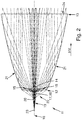
- Figure 2 shows a top view of a front lens system 11 according to the invention with a light entry surface 12, which has a first central region 14, which extends around a longitudinal axis 16, and a second region 15 arranged outside this central region 14.
- the first central area 14 is convexly curved
- the second area 15 is concave.
- a light source 18 for emitting light beams is arranged in a first focal point 17 on the longitudinal axis 16 running through the light entry surface 12, which corresponds, for example, to an optical axis of the front lens system 11.
- the rays incident on the second area 15 of the light entry surface 12 are refracted by the latter in such a way that they continue to diverging in the direction of the light exit surface 13 in the front optics 11 - although they are bundled a little.
- the light beams coupled in via the second region 15 strike a reflection surface 21 and are deflected by the latter in the direction of the light exit surface 13.
- the reflection surfaces 21 reflect the light by means of total reflection (TIR). If you follow through the second area 15 of the Light entry surface 12 broken rays back to their origin on the basis of the imaginary ray traces 22 shown, these have a common intersection in a second focal point 20, which is preferably on the longitudinal axis 16.
- the rays incident on the first central region 14 of the light entry surface 12 are refracted by the latter in such a way that they are not parallelized in the front optics 11, but - although they are bundled a little - continue to diverge in the direction of the light exit surface 13. If the rays refracted at the first central area 14 of the light entry surface 12 are traced back to their origin on the basis of the imaginary ray profiles 19, these have a common intersection at a third focal point 23, which is preferably also located on the longitudinal axis 16 (cf. Fig. 3 ). It can clearly be seen that the prior art object - the first focal point 17, in which the light source 18 is located, is arranged at a distance from the third focal point 23. Furthermore, the second focal point 20 is preferably between the first focal point 17 in which the light source 18 is arranged and the third focal point 23.
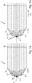
- the front optical system 11 has overlapping wave structures in two mutually perpendicular planes, so that a plurality of cushion optics 24 results at the light exit surface 13.
- the wave structures preferably have the same wavelengths and the same amplitudes.
- the light passing through the cushion optics 24 experiences additional scattering in the desired manner.
- Light also other optically effective elements can be formed, for example. Cylinder lenses or prisms.
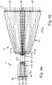
- Figure 4a is a front lens 1 known from the prior art according to Fig. 1a shown.
- An outer region 27 of the light coupling-out surface 28 is illuminated by rays that pass through the second light coupling-in surface 4, and an inner region 29 of the light coupling-out surface 28 by rays that pass through the first light coupling-in surface 3.
- the direction of the light rays runs in Fig. 4a from right to left.
- FIG 4b is, in comparison, a top view of a front optical system 11 according to the invention Fig. 2 together with exemplary illumination of the light exit surface 13, the direction of the light rays running from left to right here.
- An outer region 25 of the light exit surface 13 is illuminated by rays passing through the second region 15 of the light entry surface 12 and an inner, central region 26 of the light exit surface 13 by the rays passing through the first central region 14 of the light entry surface 12.
- the dimensions of the first central area 14 of the front lens system 11 and the first coupling surface 3 of the known front lens system 1 and the respective focal lengths of the front lens systems 1, 11 4a and 4b are comparable.
- the front optical system 11 according to the invention Fig. 4b has a light exit surface 13 with a significantly larger outer region 25 and a significantly larger inner region 26 than the known front lens system 1 Fig. 4a ,
- the front optical system 11 can have a light exit surface 13 with a flat or an elongated extension in a plane transverse to the longitudinal axis 16.
- the Light exit surface 13 have the shape of a circle, an ellipse, a square, a rectangle or any polygon, possibly with rounded corners.
- the outer second region 15 of the light entry surface 12 surrounds the central first region 14 in an annular manner over its entire circumference. If the light exit surface 13 is elongated with a large width and a very low height in comparison, it is conceivable that the central first region 14 extends over the entire height and the outer second region 15 only in width next to the first region 14 is arranged.
- the front optical system 11 has a plate-shaped extension, as shown, for example, in FIG Fig. 5a is shown, the light entry surface 12 being formed on a first narrow side 32 and the light exit surface 13 being formed on a second narrow side 33 of the plate-shaped optical attachment 11 opposite the first narrow side 32.
- the light entry surface 12, but above all the light exit surface 13 of the front lens system 11, has a substantially larger extension in an X direction (width) 36 than one in the Y direction (height) 37.
- the longitudinal axis 16 extends in a Z direction 35 and extends through the light entry and exit surfaces 12, 13.
- the light entry and exit surfaces 12, 13 thus lie in an XY plane that is perpendicular to the Z direction.
- the front lens system 11 has two reflection surfaces 38 formed between the light entry surface 12 and the light exit surface 13 on opposite longitudinal sides.
- the reflection surfaces 38 are in a longitudinal section along the Longitudinal axis 16 and parallel to a surface extension of the front lens system 11 (XZ plane) preferably parabolic, the longitudinal axis 16 forming a parabolic axis of the two parabolic reflection surfaces 38.
- Light rays striking the reflection surfaces 38 are reflected by total reflection (TIR) and deflected to the light exit surface 13.
- TIR total reflection
- the parabolic narrow sides 38 can be straight or curved, preferably concave.
- FIG. 5b shows a perspective view of an attachment optics arrangement 41 according to the invention in a preferred embodiment.
- the attachment optics arrangement 41 comprises four attachment optics 11 according to the invention, each offset by 45 ° from one another about a common longitudinal axis 44, as shown, for example, in FIG Fig. 5a is shown.
- the longitudinal axes 16 of the front optics 11 overlap and form the common longitudinal axis 44.
- the edges between the individual front optics 11 are rounded in order to facilitate the manufacture of the front optical system 41.
- a light exit surface 43 is formed by the light exit surfaces 13 of the individual front optics 11 and extends rotationally symmetrically about the longitudinal axis 44.
- a light entry surface 42 of the front optics arrangement 41 is composed of the entrance surfaces 12 of the four front optics 11.
- Figure 8 shows an example of an attachment optics arrangement 41 according to the invention Fig. 5b achievable light distribution.
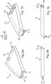
- Figure 6a shows a perspective view of an optical attachment 51 according to the invention in another preferred embodiment.
- the front optical system 11 according to the invention Fig. 2 is in the Y direction 37 with a standard coupling profile 2 1a and 1b extruded.
- a light entry surface 12 thus includes a coupling profile 2 in the XZ plane Fig. 2 and a coupling profile 2 in the XY plane 1a and 1b ,
- the light beams are parallelized in the YZ plane and expanded in the XZ plane to the entire width of the light exit surface 53 which is elongated in the X direction 36.
- the front lens 51 according to the invention has a Fresnel optical structure 54 extending in the XZ plane on the light exit surface 53.
- Figure 6b shows a side view of the front lens system 51 Fig. 6a.
- Figure 7a shows a perspective view of an attachment lens 61.
- the light entry surface 12 has been folded down with respect to the longitudinal axis 16 or the light exit surface 63 about an imaginary axis running in the X direction 36.
- the light entry surface 12 is approximately perpendicular to the surface extension of the light exit surface 63 with its surface extension.
- the surfaces 12, 13 are also arranged at any other angle to one another. Angles in a range from 45 ° to 135 ° are particularly preferred.
- the light beams coupled in through the entry surface 12 fall in the front optics 61 onto a reflection surface 62, which deflects the beams in the direction of the light exit surface 63.
- the reflection surface 62 may have a curvature or in the YZ plane and / or in the XZ plane.
- the attachment optics 61 on the light exit surface 63 are located in the XZ plane extending Fresnel optical structure 64. This can be superimposed by a wave structure 65 which also extends in the XZ plane.
- Figure 7b shows a side view of the front optics 61 Fig. 7a ,
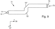
- Figure 9 shows a side view of a front lens system 71, which is bent twice in each case by approximately 90 ° between the light entry surface and the light exit surface.
- Each kink is assigned a reflection surface 72 ′, 72 ′′ for deflecting the light beams.
- the light exit surface is designated 73, the Fresnel structure on the exit surface 74.
- the present invention makes it possible, in particular by means of a special configuration of the light entry surface 12, 42, in at least one of the X or. Y dimensions to achieve a relatively large expansion of the light-emitting surface 13, 43, 53.
Landscapes
- Physics & Mathematics (AREA)
- General Physics & Mathematics (AREA)
- Optics & Photonics (AREA)
- Engineering & Computer Science (AREA)
- General Engineering & Computer Science (AREA)
- Lenses (AREA)
Claims (11)
- Optique auxiliaire (11; 51) en matériau transparent destinée à focaliser de la lumière d'une source lumineuse (18), dans laquelle l'optique auxiliaire (11; 51) présente une surface d'entrée de lumière (12), par laquelle de la lumière émise par la source lumineuse (18) pénètre dans l'optique auxiliaire (11; 51), et une surface de sortie de lumière (13, 43, 53), et l'optique auxiliaire (11; 51) présente un axe longitudinal (16) qui s'étend par la surface d'entrée de lumière (12) et la surface de sortie de lumière (13, 43, 53) et sur laquelle est disposée la source lumineuse (18) dans un premier foyer (17), la surface d'entrée de lumière (12) étant subdivisée en une première zone (14) centrale et une deuxième zone (15) disposée à côté de la première zone (14), la deuxième zone (15) étant conçue de façon telle que des rayons lumineux émis par la source lumineuse (18) se coupent, après un passage par la deuxième zone (15) et une réfraction par la deuxième zone (15), dans un deuxième foyer (20) virtuel, et que la première zone (14) centrale est conçue de façon telle que les rayons lumineux émis par la source lumineuse (18) se coupent après un passage par la première zone (14) et une réfraction par la première zone (14), en un troisième foyer (23) virtuel, caractérisé en ce que de la lumière concentrée par la surface de sortie de lumière (13, 43, 53) sort de l'optique auxiliaire (11; 51), en ce que l'optique auxiliaire (11; 51) présente une extension en forme de plaque, et en ce que le second foyer (20) est disposé entre le premier foyer (17) et le troisième foyer (23).
- Optique auxiliaire (11; 51) selon la revendication 1, caractérisée en ce que la première zone centrale (14) et la deuxième zone (15) sont respectivement bombées de façon symétrique par rapport à l'axe longitudinal (16) .
- Optique auxiliaire (11; 51) selon la revendication 2, caractérisée en ce que le deuxième foyer (20) et le troisième foyer (23) sont disposés sur l'axe longitudinal (16) de l'optique auxiliaire (11; 51).
- Optique auxiliaire (11; 51) selon l'une des revendications 1 à 3, caractérisée en ce que la première zone centrale (14) est bombée de façon convexe.
- Optique auxiliaire (11; 51) selon l'une des revendications 1 à 4, caractérisée en ce que la deuxième zone (15) est bombée de façon concave.
- Optique auxiliaire (11; 51) selon l'une des revendications 1 à 5, caractérisée en ce que l'axe longitudinal (16) est un axe optique de l'optique auxiliaire (11; 51).
- Optique auxiliaire (11; 51) selon l'une des revendications 1 à 6, caractérisée en ce que deux côtés étroits (38) opposés de l'optique auxiliaire (11; 51) en forme de plaque, formés entre la surface d'entrée de lumière (12) et la surface de sortie de lumière (13, 43, 53), sont réalisés en forme de parabole, vue en une coupe longitudinale le long de l'axe longitudinal (16) et parallèlement à une étendue de surface de l'optique auxiliaire (11; 51), l'axe longitudinal (16) formant un axe parabolique des deux côtés étroits en forme de parabole (38).
- Optique auxiliaire (11; 51) selon l'une des revendications 1 à 7, caractérisée en ce que la surface de sortie de lumière (13, 43, 53) présente, au moins dans un plan, une structure d'ondes.
- Optique auxiliaire (11; 51) selon la revendication 8, caractérisée en ce que la surface de sortie de lumière (13, 43, 53) présente des structures d'ondes qui se chevauchent dans deux plans perpendiculaires l'un à l'autre.
- Agencement d'optiques auxiliaires (41) comportant plusieurs optiques auxiliaires (11; 51) selon l'une des revendications précédentes, dans lequel les axes longitudinaux (16) des optiques auxiliaires (11; 51) coïncident et les optiques auxiliaires (11; 51) sont disposées autour des axes longitudinaux communs (44) de façon décalée de plusieurs degrés angulaires les unes par rapport aux autres.
- Agencement d'optiques auxiliaires (41) selon la revendication 10, caractérisé en ce que l'agencement d'optiques auxiliaires (41) comporte quatre optiques auxiliaires (11; 51) qui sont disposées autour des axes longitudinaux communs (44) de façon décalée les unes par rapport aux autres de 45° respectivement.
Applications Claiming Priority (1)
| Application Number | Priority Date | Filing Date | Title |
|---|---|---|---|
| DE102015222495.3A DE102015222495A1 (de) | 2015-11-13 | 2015-11-13 | Vorsatzoptik und Vorsatzoptikanordnung mit mehreren Vorsatzoptiken |
Publications (2)
| Publication Number | Publication Date |
|---|---|
| EP3168657A1 EP3168657A1 (fr) | 2017-05-17 |
| EP3168657B1 true EP3168657B1 (fr) | 2020-01-01 |
Family
ID=57288256
Family Applications (1)
| Application Number | Title | Priority Date | Filing Date |
|---|---|---|---|
| EP16198483.6A Active EP3168657B1 (fr) | 2015-11-13 | 2016-11-11 | Optique auxiliaire et système d'optique auxiliaire comprenant plusieurs optiques auxiliaires |
Country Status (2)
| Country | Link |
|---|---|
| EP (1) | EP3168657B1 (fr) |
| DE (1) | DE102015222495A1 (fr) |
Cited By (1)
| Publication number | Priority date | Publication date | Assignee | Title |
|---|---|---|---|---|
| US10837618B2 (en) * | 2018-06-04 | 2020-11-17 | Stanley Electric Co., Ltd. | Vehicular lamp |
Families Citing this family (7)
| Publication number | Priority date | Publication date | Assignee | Title |
|---|---|---|---|---|
| DE102017111912A1 (de) * | 2017-05-31 | 2018-12-06 | Itz Innovations- Und Technologiezentrum Gmbh | Modularer Lichtleiter |
| JP2019125532A (ja) * | 2018-01-18 | 2019-07-25 | 株式会社小糸製作所 | 灯具 |
| JP2019212471A (ja) * | 2018-06-04 | 2019-12-12 | スタンレー電気株式会社 | 車両用灯具 |
| CN113028356B (zh) * | 2019-12-09 | 2023-07-28 | 堤维西交通工业股份有限公司 | 透镜装置 |
| CH717330B1 (de) * | 2020-07-27 | 2021-10-29 | Polycontact Ag | Optik für eine Beleuchtungseinrichtung und Beleuchtungseinrichtung. |
| KR102869864B1 (ko) * | 2020-10-26 | 2025-10-13 | 현대모비스 주식회사 | 자동차용 램프 및 그 램프를 포함하는 자동차 |
| DE102023109202A1 (de) * | 2023-04-12 | 2024-10-17 | Marelli Automotive Lighting Reutlingen (Germany) GmbH | Beleuchtungseinrichtung mit einer volumenstreuenden TIR-Optik |
Family Cites Families (7)
| Publication number | Priority date | Publication date | Assignee | Title |
|---|---|---|---|---|
| US7438454B2 (en) * | 2005-11-29 | 2008-10-21 | Visteon Global Technologies, Inc. | Light assembly for automotive lighting applications |
| DE102007063569B4 (de) * | 2007-12-28 | 2012-02-16 | Automotive Lighting Reutlingen Gmbh | Beleuchtungseinrichtung für Fahrzeuge |
| DE102010013931A1 (de) | 2010-04-06 | 2011-10-06 | Automotive Lighting Reutlingen Gmbh | Modulare Lichtleitervorrichtung für Kraftfahrzeugbeleuchtungseinrichtungen |
| JP5010010B2 (ja) * | 2010-04-16 | 2012-08-29 | フェニックス電機株式会社 | 発光装置 |
| CN102829437B (zh) * | 2011-06-15 | 2015-04-01 | 光宝科技股份有限公司 | 光罩及具光罩的灯具 |
| FR2993633B1 (fr) | 2012-07-23 | 2018-12-07 | Valeo Vision | Guide de lumiere pour un dispositif d'eclairage et/ou de signalisation de vehicule automobile |
| DE202013101509U1 (de) * | 2013-04-09 | 2013-04-23 | Fu An Industrial Co., Ltd. | Optische Linse für Streifenbeleuchtungen |
-
2015
- 2015-11-13 DE DE102015222495.3A patent/DE102015222495A1/de not_active Withdrawn
-
2016
- 2016-11-11 EP EP16198483.6A patent/EP3168657B1/fr active Active
Non-Patent Citations (1)
| Title |
|---|
| None * |
Cited By (1)
| Publication number | Priority date | Publication date | Assignee | Title |
|---|---|---|---|---|
| US10837618B2 (en) * | 2018-06-04 | 2020-11-17 | Stanley Electric Co., Ltd. | Vehicular lamp |
Also Published As
| Publication number | Publication date |
|---|---|
| DE102015222495A1 (de) | 2017-05-18 |
| EP3168657A1 (fr) | 2017-05-17 |
Similar Documents
| Publication | Publication Date | Title |
|---|---|---|
| EP3168657B1 (fr) | Optique auxiliaire et système d'optique auxiliaire comprenant plusieurs optiques auxiliaires | |
| EP2607774B1 (fr) | Dispositif d'éclairage d'un véhicule automobile avec une surface lumineuse longue et plane | |
| EP2306073B1 (fr) | Module d'éclairage pour un dispositif d'éclairage d'un véhicule automobile | |
| EP3084292B1 (fr) | Lampe de véhicule à moteur équipée d'un guide de lumière | |
| EP1978296A2 (fr) | Corps conducteur de lumière et unité d'éclairage dotée d'un corps conducteur de lumière | |
| EP3899358B1 (fr) | Dispositif d'éclairage pour un phare de véhicule automobile ainsi que phare de véhicule automobile | |
| EP2618045A1 (fr) | Dispositif dýéclairage pour un véhicule automobile | |
| DE102012214138B4 (de) | Lichtmodul einer Kfz-Beleuchtungseinrichtung mit Linsenelement und Reflektor | |
| DE102011055429A1 (de) | Beleuchtungsvorrichtung für Fahrzeuge | |
| DE102017115899A1 (de) | Kraftfahrzeugleuchte und Kraftfahrzeugscheinwerfer mit einer solchen Leuchte | |
| DE202014003078U1 (de) | Optisches Element und Beleuchtungseinrichtung mit optischem Element | |
| EP2490052B1 (fr) | Dispositif d'éclairage d'un véhicule automobile | |
| EP2444720B1 (fr) | Dispositif d'éclairage pour un véhicule automobile | |
| EP2835578B1 (fr) | Élément conducteur de lumière en forme de plaque en matériau transparent et module d'éclairage pour un dispositif d'éclairage de véhicule automobile doté d'un tel élément conducteur de lumière | |
| DE102012215124B4 (de) | Beleuchtungseinrichtung mit mehreren Lichtquellen und Lichtleitkörpern sowie einem Reflektor | |
| DE102021117696A1 (de) | Optik für eine Beleuchtungseinrichtung und Beleuchtungseinrichtung | |
| DE102015204735A1 (de) | Lichtleiterelement einer Kraftfahrzeug-Beleuchtungseinrichtung und Kraftfahrzeug-Beleuchtungseinrichtung mit einem solchen Lichtleiterelement | |
| DE102015207960A1 (de) | Plattenförmiges Lichtleiterelement zum Einsatz in einer Beleuchtungseinrichtung eines Kraftfahrzeugs und Beleuchtungseinrichtung mit einem solchen Lichtleiterelement | |
| EP3477193A1 (fr) | Couvercle pour un module lumineux et module lumineux | |
| EP3412963B1 (fr) | Dispositif composant transparent d'un module d'éclairage et module d'éclairage doté d'un tel dispositif composant transparent | |
| DE102012211748A1 (de) | Optisches kollimationssystem | |
| DE102018113151B4 (de) | Leuchtenmodul für eine Kraftfahrzeugleuchte | |
| DE202017100585U1 (de) | Beleuchtungseinrichtung eines Kraftfahrzeugs | |
| DE102022106420A1 (de) | Signalleuchte für eine Kraftfahrzeugbeleuchtungseinrichtung | |
| DE102019131685A1 (de) | Lichtmodul, Lichtleiteranordnung, Beleuchtungseinrichtung und Kraftfahrzeug |
Legal Events
| Date | Code | Title | Description |
|---|---|---|---|
| PUAI | Public reference made under article 153(3) epc to a published international application that has entered the european phase |
Free format text: ORIGINAL CODE: 0009012 |
|
| STAA | Information on the status of an ep patent application or granted ep patent |
Free format text: STATUS: THE APPLICATION HAS BEEN PUBLISHED |
|
| AK | Designated contracting states |
Kind code of ref document: A1 Designated state(s): AL AT BE BG CH CY CZ DE DK EE ES FI FR GB GR HR HU IE IS IT LI LT LU LV MC MK MT NL NO PL PT RO RS SE SI SK SM TR |
|
| AX | Request for extension of the european patent |
Extension state: BA ME |
|
| STAA | Information on the status of an ep patent application or granted ep patent |
Free format text: STATUS: REQUEST FOR EXAMINATION WAS MADE |
|
| 17P | Request for examination filed |
Effective date: 20170928 |
|
| RBV | Designated contracting states (corrected) |
Designated state(s): AL AT BE BG CH CY CZ DE DK EE ES FI FR GB GR HR HU IE IS IT LI LT LU LV MC MK MT NL NO PL PT RO RS SE SI SK SM TR |
|
| REG | Reference to a national code |
Ref country code: DE Ref legal event code: R079 Ref document number: 502016008225 Country of ref document: DE Free format text: PREVIOUS MAIN CLASS: G02B0003000000 Ipc: F21S0043239000 |
|
| RIC1 | Information provided on ipc code assigned before grant |
Ipc: G02B 19/00 20060101ALI20190408BHEP Ipc: F21V 8/00 20060101ALI20190408BHEP Ipc: F21V 5/04 20060101ALI20190408BHEP Ipc: F21S 43/239 20180101AFI20190408BHEP Ipc: F21Y 115/10 20160101ALI20190408BHEP Ipc: F21S 43/247 20180101ALI20190408BHEP Ipc: G02B 3/08 20060101ALI20190408BHEP Ipc: F21S 43/243 20180101ALI20190408BHEP Ipc: G02B 3/00 20060101ALI20190408BHEP Ipc: F21S 43/31 20180101ALI20190408BHEP Ipc: F21S 43/241 20180101ALI20190408BHEP Ipc: F21V 7/00 20060101ALI20190408BHEP |
|
| GRAP | Despatch of communication of intention to grant a patent |
Free format text: ORIGINAL CODE: EPIDOSNIGR1 |
|
| STAA | Information on the status of an ep patent application or granted ep patent |
Free format text: STATUS: GRANT OF PATENT IS INTENDED |
|
| INTG | Intention to grant announced |
Effective date: 20190603 |
|
| GRAS | Grant fee paid |
Free format text: ORIGINAL CODE: EPIDOSNIGR3 |
|
| GRAA | (expected) grant |
Free format text: ORIGINAL CODE: 0009210 |
|
| STAA | Information on the status of an ep patent application or granted ep patent |
Free format text: STATUS: THE PATENT HAS BEEN GRANTED |
|
| AK | Designated contracting states |
Kind code of ref document: B1 Designated state(s): AL AT BE BG CH CY CZ DE DK EE ES FI FR GB GR HR HU IE IS IT LI LT LU LV MC MK MT NL NO PL PT RO RS SE SI SK SM TR |
|
| REG | Reference to a national code |
Ref country code: GB Ref legal event code: FG4D Free format text: NOT ENGLISH |
|
| REG | Reference to a national code |
Ref country code: CH Ref legal event code: EP Ref country code: AT Ref legal event code: REF Ref document number: 1220208 Country of ref document: AT Kind code of ref document: T Effective date: 20200115 |
|
| REG | Reference to a national code |
Ref country code: DE Ref legal event code: R096 Ref document number: 502016008225 Country of ref document: DE |
|
| REG | Reference to a national code |
Ref country code: IE Ref legal event code: FG4D Free format text: LANGUAGE OF EP DOCUMENT: GERMAN |
|
| REG | Reference to a national code |
Ref country code: NL Ref legal event code: MP Effective date: 20200101 |
|
| REG | Reference to a national code |
Ref country code: LT Ref legal event code: MG4D |
|
| PG25 | Lapsed in a contracting state [announced via postgrant information from national office to epo] |
Ref country code: LT Free format text: LAPSE BECAUSE OF FAILURE TO SUBMIT A TRANSLATION OF THE DESCRIPTION OR TO PAY THE FEE WITHIN THE PRESCRIBED TIME-LIMIT Effective date: 20200101 Ref country code: PT Free format text: LAPSE BECAUSE OF FAILURE TO SUBMIT A TRANSLATION OF THE DESCRIPTION OR TO PAY THE FEE WITHIN THE PRESCRIBED TIME-LIMIT Effective date: 20200527 Ref country code: CZ Free format text: LAPSE BECAUSE OF FAILURE TO SUBMIT A TRANSLATION OF THE DESCRIPTION OR TO PAY THE FEE WITHIN THE PRESCRIBED TIME-LIMIT Effective date: 20200101 Ref country code: NL Free format text: LAPSE BECAUSE OF FAILURE TO SUBMIT A TRANSLATION OF THE DESCRIPTION OR TO PAY THE FEE WITHIN THE PRESCRIBED TIME-LIMIT Effective date: 20200101 Ref country code: FI Free format text: LAPSE BECAUSE OF FAILURE TO SUBMIT A TRANSLATION OF THE DESCRIPTION OR TO PAY THE FEE WITHIN THE PRESCRIBED TIME-LIMIT Effective date: 20200101 Ref country code: NO Free format text: LAPSE BECAUSE OF FAILURE TO SUBMIT A TRANSLATION OF THE DESCRIPTION OR TO PAY THE FEE WITHIN THE PRESCRIBED TIME-LIMIT Effective date: 20200401 Ref country code: RS Free format text: LAPSE BECAUSE OF FAILURE TO SUBMIT A TRANSLATION OF THE DESCRIPTION OR TO PAY THE FEE WITHIN THE PRESCRIBED TIME-LIMIT Effective date: 20200101 |
|
| PG25 | Lapsed in a contracting state [announced via postgrant information from national office to epo] |
Ref country code: GR Free format text: LAPSE BECAUSE OF FAILURE TO SUBMIT A TRANSLATION OF THE DESCRIPTION OR TO PAY THE FEE WITHIN THE PRESCRIBED TIME-LIMIT Effective date: 20200402 Ref country code: HR Free format text: LAPSE BECAUSE OF FAILURE TO SUBMIT A TRANSLATION OF THE DESCRIPTION OR TO PAY THE FEE WITHIN THE PRESCRIBED TIME-LIMIT Effective date: 20200101 Ref country code: LV Free format text: LAPSE BECAUSE OF FAILURE TO SUBMIT A TRANSLATION OF THE DESCRIPTION OR TO PAY THE FEE WITHIN THE PRESCRIBED TIME-LIMIT Effective date: 20200101 Ref country code: SE Free format text: LAPSE BECAUSE OF FAILURE TO SUBMIT A TRANSLATION OF THE DESCRIPTION OR TO PAY THE FEE WITHIN THE PRESCRIBED TIME-LIMIT Effective date: 20200101 Ref country code: BG Free format text: LAPSE BECAUSE OF FAILURE TO SUBMIT A TRANSLATION OF THE DESCRIPTION OR TO PAY THE FEE WITHIN THE PRESCRIBED TIME-LIMIT Effective date: 20200401 Ref country code: IS Free format text: LAPSE BECAUSE OF FAILURE TO SUBMIT A TRANSLATION OF THE DESCRIPTION OR TO PAY THE FEE WITHIN THE PRESCRIBED TIME-LIMIT Effective date: 20200501 |
|
| REG | Reference to a national code |
Ref country code: DE Ref legal event code: R097 Ref document number: 502016008225 Country of ref document: DE |
|
| PG25 | Lapsed in a contracting state [announced via postgrant information from national office to epo] |
Ref country code: DK Free format text: LAPSE BECAUSE OF FAILURE TO SUBMIT A TRANSLATION OF THE DESCRIPTION OR TO PAY THE FEE WITHIN THE PRESCRIBED TIME-LIMIT Effective date: 20200101 Ref country code: SM Free format text: LAPSE BECAUSE OF FAILURE TO SUBMIT A TRANSLATION OF THE DESCRIPTION OR TO PAY THE FEE WITHIN THE PRESCRIBED TIME-LIMIT Effective date: 20200101 Ref country code: EE Free format text: LAPSE BECAUSE OF FAILURE TO SUBMIT A TRANSLATION OF THE DESCRIPTION OR TO PAY THE FEE WITHIN THE PRESCRIBED TIME-LIMIT Effective date: 20200101 Ref country code: RO Free format text: LAPSE BECAUSE OF FAILURE TO SUBMIT A TRANSLATION OF THE DESCRIPTION OR TO PAY THE FEE WITHIN THE PRESCRIBED TIME-LIMIT Effective date: 20200101 Ref country code: ES Free format text: LAPSE BECAUSE OF FAILURE TO SUBMIT A TRANSLATION OF THE DESCRIPTION OR TO PAY THE FEE WITHIN THE PRESCRIBED TIME-LIMIT Effective date: 20200101 Ref country code: SK Free format text: LAPSE BECAUSE OF FAILURE TO SUBMIT A TRANSLATION OF THE DESCRIPTION OR TO PAY THE FEE WITHIN THE PRESCRIBED TIME-LIMIT Effective date: 20200101 |
|
| PLBE | No opposition filed within time limit |
Free format text: ORIGINAL CODE: 0009261 |
|
| STAA | Information on the status of an ep patent application or granted ep patent |
Free format text: STATUS: NO OPPOSITION FILED WITHIN TIME LIMIT |
|
| 26N | No opposition filed |
Effective date: 20201002 |
|
| PG25 | Lapsed in a contracting state [announced via postgrant information from national office to epo] |
Ref country code: IT Free format text: LAPSE BECAUSE OF FAILURE TO SUBMIT A TRANSLATION OF THE DESCRIPTION OR TO PAY THE FEE WITHIN THE PRESCRIBED TIME-LIMIT Effective date: 20200101 |
|
| PG25 | Lapsed in a contracting state [announced via postgrant information from national office to epo] |
Ref country code: SI Free format text: LAPSE BECAUSE OF FAILURE TO SUBMIT A TRANSLATION OF THE DESCRIPTION OR TO PAY THE FEE WITHIN THE PRESCRIBED TIME-LIMIT Effective date: 20200101 Ref country code: PL Free format text: LAPSE BECAUSE OF FAILURE TO SUBMIT A TRANSLATION OF THE DESCRIPTION OR TO PAY THE FEE WITHIN THE PRESCRIBED TIME-LIMIT Effective date: 20200101 |
|
| PG25 | Lapsed in a contracting state [announced via postgrant information from national office to epo] |
Ref country code: MC Free format text: LAPSE BECAUSE OF FAILURE TO SUBMIT A TRANSLATION OF THE DESCRIPTION OR TO PAY THE FEE WITHIN THE PRESCRIBED TIME-LIMIT Effective date: 20200101 |
|
| REG | Reference to a national code |
Ref country code: CH Ref legal event code: PL |
|
| GBPC | Gb: european patent ceased through non-payment of renewal fee |
Effective date: 20201111 |
|
| PG25 | Lapsed in a contracting state [announced via postgrant information from national office to epo] |
Ref country code: LU Free format text: LAPSE BECAUSE OF NON-PAYMENT OF DUE FEES Effective date: 20201111 |
|
| REG | Reference to a national code |
Ref country code: BE Ref legal event code: MM Effective date: 20201130 |
|
| PG25 | Lapsed in a contracting state [announced via postgrant information from national office to epo] |
Ref country code: LI Free format text: LAPSE BECAUSE OF NON-PAYMENT OF DUE FEES Effective date: 20201130 Ref country code: CH Free format text: LAPSE BECAUSE OF NON-PAYMENT OF DUE FEES Effective date: 20201130 |
|
| PG25 | Lapsed in a contracting state [announced via postgrant information from national office to epo] |
Ref country code: IE Free format text: LAPSE BECAUSE OF NON-PAYMENT OF DUE FEES Effective date: 20201111 |
|
| PG25 | Lapsed in a contracting state [announced via postgrant information from national office to epo] |
Ref country code: GB Free format text: LAPSE BECAUSE OF NON-PAYMENT OF DUE FEES Effective date: 20201111 |
|
| PG25 | Lapsed in a contracting state [announced via postgrant information from national office to epo] |
Ref country code: TR Free format text: LAPSE BECAUSE OF FAILURE TO SUBMIT A TRANSLATION OF THE DESCRIPTION OR TO PAY THE FEE WITHIN THE PRESCRIBED TIME-LIMIT Effective date: 20200101 Ref country code: MT Free format text: LAPSE BECAUSE OF FAILURE TO SUBMIT A TRANSLATION OF THE DESCRIPTION OR TO PAY THE FEE WITHIN THE PRESCRIBED TIME-LIMIT Effective date: 20200101 Ref country code: CY Free format text: LAPSE BECAUSE OF FAILURE TO SUBMIT A TRANSLATION OF THE DESCRIPTION OR TO PAY THE FEE WITHIN THE PRESCRIBED TIME-LIMIT Effective date: 20200101 |
|
| PG25 | Lapsed in a contracting state [announced via postgrant information from national office to epo] |
Ref country code: MK Free format text: LAPSE BECAUSE OF FAILURE TO SUBMIT A TRANSLATION OF THE DESCRIPTION OR TO PAY THE FEE WITHIN THE PRESCRIBED TIME-LIMIT Effective date: 20200101 Ref country code: AL Free format text: LAPSE BECAUSE OF FAILURE TO SUBMIT A TRANSLATION OF THE DESCRIPTION OR TO PAY THE FEE WITHIN THE PRESCRIBED TIME-LIMIT Effective date: 20200101 |
|
| PG25 | Lapsed in a contracting state [announced via postgrant information from national office to epo] |
Ref country code: BE Free format text: LAPSE BECAUSE OF NON-PAYMENT OF DUE FEES Effective date: 20201130 |
|
| PGFP | Annual fee paid to national office [announced via postgrant information from national office to epo] |
Ref country code: FR Payment date: 20221021 Year of fee payment: 7 |
|
| REG | Reference to a national code |
Ref country code: AT Ref legal event code: MM01 Ref document number: 1220208 Country of ref document: AT Kind code of ref document: T Effective date: 20211111 |
|
| PG25 | Lapsed in a contracting state [announced via postgrant information from national office to epo] |
Ref country code: AT Free format text: LAPSE BECAUSE OF NON-PAYMENT OF DUE FEES Effective date: 20211111 |
|
| P01 | Opt-out of the competence of the unified patent court (upc) registered |
Effective date: 20230508 |
|
| PG25 | Lapsed in a contracting state [announced via postgrant information from national office to epo] |
Ref country code: FR Free format text: LAPSE BECAUSE OF NON-PAYMENT OF DUE FEES Effective date: 20231130 |
|
| PG25 | Lapsed in a contracting state [announced via postgrant information from national office to epo] |
Ref country code: FR Free format text: LAPSE BECAUSE OF NON-PAYMENT OF DUE FEES Effective date: 20231130 |
|
| REG | Reference to a national code |
Ref country code: DE Ref legal event code: R084 Ref document number: 502016008225 Country of ref document: DE |
|
| PGFP | Annual fee paid to national office [announced via postgrant information from national office to epo] |
Ref country code: DE Payment date: 20251022 Year of fee payment: 10 |
|
| REG | Reference to a national code |
Ref country code: DE Ref legal event code: R081 Ref document number: 502016008225 Country of ref document: DE Owner name: MARELLI GERMANY GMBH, DE Free format text: FORMER OWNER: AUTOMOTIVE LIGHTING REUTLINGEN GMBH, 72762 REUTLINGEN, DE |