EP3169073A1 - Dispositif de transmission, procédé de transmission, dispositif de réception, et procédé de réception - Google Patents
Dispositif de transmission, procédé de transmission, dispositif de réception, et procédé de réception Download PDFInfo
- Publication number
- EP3169073A1 EP3169073A1 EP15818243.6A EP15818243A EP3169073A1 EP 3169073 A1 EP3169073 A1 EP 3169073A1 EP 15818243 A EP15818243 A EP 15818243A EP 3169073 A1 EP3169073 A1 EP 3169073A1
- Authority
- EP
- European Patent Office
- Prior art keywords
- component
- transmission
- information
- indicates
- selection
- Prior art date
- Legal status (The legal status is an assumption and is not a legal conclusion. Google has not performed a legal analysis and makes no representation as to the accuracy of the status listed.)
- Granted
Links
Images


Classifications
-
- H—ELECTRICITY
- H04—ELECTRIC COMMUNICATION TECHNIQUE
- H04H—BROADCAST COMMUNICATION
- H04H20/00—Arrangements for broadcast or for distribution combined with broadcast
- H04H20/42—Arrangements for resource management
-
- H—ELECTRICITY
- H04—ELECTRIC COMMUNICATION TECHNIQUE
- H04N—PICTORIAL COMMUNICATION, e.g. TELEVISION
- H04N21/00—Selective content distribution, e.g. interactive television or video on demand [VOD]
- H04N21/20—Servers specifically adapted for the distribution of content, e.g. VOD servers; Operations thereof
- H04N21/23—Processing of content or additional data; Elementary server operations; Server middleware
- H04N21/236—Assembling of a multiplex stream, e.g. transport stream, by combining a video stream with other content or additional data, e.g. inserting a URL [Uniform Resource Locator] into a video stream, multiplexing software data into a video stream; Remultiplexing of multiplex streams; Insertion of stuffing bits into the multiplex stream, e.g. to obtain a constant bit-rate; Assembling of a packetised elementary stream
- H04N21/23614—Multiplexing of additional data and video streams
-
- H—ELECTRICITY
- H04—ELECTRIC COMMUNICATION TECHNIQUE
- H04N—PICTORIAL COMMUNICATION, e.g. TELEVISION
- H04N21/00—Selective content distribution, e.g. interactive television or video on demand [VOD]
- H04N21/40—Client devices specifically adapted for the reception of or interaction with content, e.g. set-top-box [STB]; Operations thereof
- H04N21/45—Management operations performed by the client for facilitating the reception of or the interaction with the content or administrating data related to the end-user or to the client device itself, e.g. learning user preferences for recommending movies, resolving scheduling conflicts
- H04N21/462—Content or additional data management e.g. creating a master electronic programme guide from data received from the Internet and a Head-end or controlling the complexity of a video stream by scaling the resolution or bit-rate based on the client capabilities
- H04N21/4622—Retrieving content or additional data from different sources, e.g. from a broadcast channel and the Internet
-
- H—ELECTRICITY
- H04—ELECTRIC COMMUNICATION TECHNIQUE
- H04N—PICTORIAL COMMUNICATION, e.g. TELEVISION
- H04N21/00—Selective content distribution, e.g. interactive television or video on demand [VOD]
- H04N21/60—Network structure or processes for video distribution between server and client or between remote clients; Control signalling between clients, server and network components; Transmission of management data between server and client, e.g. sending from server to client commands for recording incoming content stream; Communication details between server and client
- H04N21/61—Network physical structure; Signal processing
- H04N21/6106—Network physical structure; Signal processing specially adapted to the downstream path of the transmission network
- H04N21/6112—Network physical structure; Signal processing specially adapted to the downstream path of the transmission network involving terrestrial transmission, e.g. DVB-T
-
- H—ELECTRICITY
- H04—ELECTRIC COMMUNICATION TECHNIQUE
- H04N—PICTORIAL COMMUNICATION, e.g. TELEVISION
- H04N21/00—Selective content distribution, e.g. interactive television or video on demand [VOD]
- H04N21/60—Network structure or processes for video distribution between server and client or between remote clients; Control signalling between clients, server and network components; Transmission of management data between server and client, e.g. sending from server to client commands for recording incoming content stream; Communication details between server and client
- H04N21/61—Network physical structure; Signal processing
- H04N21/6106—Network physical structure; Signal processing specially adapted to the downstream path of the transmission network
- H04N21/6125—Network physical structure; Signal processing specially adapted to the downstream path of the transmission network involving transmission via Internet
Definitions
- the present technology relates to a transmission device, a transmission method, a reception device, and a reception method, and more particularly, to a transmission device and the like suitable for the application to a broadcasting/communication hybrid transmission system.
- MPEG-2 TS Moving Picture Experts Group-2 Transport Stream
- RTP Real Time Protocol
- MMT MPEG Media Transport
- Patent Literature 1 JP 2013-153291A
- Non-Patent Literature 1 ISO/IEC FDIS 23008-1:2013(E) Information technology-High efficiency coding and media delivery in heterogeneous environments-Part 1: MPEG media transport (MMT)
- MMT MPEG media transport
- a concept of the present technology is a transmission device, including: a transmission stream generator configured to generate a transmission stream in which a first transmission packet including a predetermined component and a second transmission packet including signaling information related to the predetermined component are multiplexed in a time division manner; a transmitting unit configured to transmit the transmission stream via a predetermined transmission path; and an information inserting unit configured to insert component selection information into the second transmission packet.
- a transmission stream generator generates a transmission stream in which a first transmission packet including a predetermined component and a second transmission packet including signaling information related to the predetermined component are multiplexed in a time division manner.
- a transmitting unit transmits the transmission stream to a reception side via a predetermined transmission path.
- An information inserting unit inserts component selection information into the second transmission packet.
- the component selection information may include selective layer information for performing fixed selection, composite layer information for performing composition, and adaptive layer information for performing dynamic switching from the top.
- information for acquiring an acquisition destination may be included in information of each component that is selectable in an adaptive layer.
- the component selection information is inserted into the second transmission packet.
- easiness of component selection can be secured at the reception side.
- the transmission packet may be an MMT packet
- a component structure table including the component selection information may be arranged in the package access message together with an MMT package table.
- a component of the component structure table may be associated with an asset of the MMT package table using a component tag.
- a reception device including: a first receiving unit configured to receive, via a first transmission path, a transmission stream in which a first transmission packet including a predetermined component and a second transmission packet including signaling information related to the predetermined component are multiplexed in a time division manner; and a second receiving unit configured to receive a transmission stream in which a third transmission packet including a predetermined component is arranged via a second transmission path.
- Component selection information is inserted into the second transmission packet, and the reception device further includes a component selecting unit configured to select a component to be presented based on the component selection information.
- a first receiving unit receives a transmission stream via a first transmission path.
- a first transmission packet including a predetermined component and a second transmission packet including signaling information related to the predetermined component are multiplexed in a time division manner in the transmission stream.
- a second receiving unit receives a third transmission packet including a predetermined component via a second transmission path.
- the first transmission path may be a broadcast transmission path
- the second transmission path may be a network transmission path.
- the component selection information is inserted into the second transmission packet.
- a component selecting unit selects a component to be presented based on the component selection information. For example, the component selecting unit may cause a selection graphic user interface to be displayed on a screen when there is a variation related to a specific attribute to be selected by a user in the component selection information.
- the component selection information may include selective layer information for performing fixed selection, composite layer information for performing composition, and adaptive layer information for performing dynamic switching from the top.
- information for acquiring an acquisition destination may be included in information of each component that is selectable in the adaptive layer.
- a component to be presented is selected based on the component selection information into which the second transmission packet is inserted.
- easiness of component selection can be secured.
- FIG. 1 illustrates an exemplary configuration of a broadcasting/communication hybrid system 10.
- a broadcast transmission system 110 and a delivery server 120 are arranged on a transmission side, and a receiver 200 is arranged on a reception side.
- the broadcast transmission system 110 transmits, for example, a broadcast signal of an Internet Protocol (IP) scheme including transmission media (component).
- IP Internet Protocol
- transmission media there are timed media and non-timed media.
- the timed media is stream data such as a video, audio, captions, or the like.
- the non-timed media is file data such as HTML document data or other data.
- the delivery server 120 delivers a transmission stream in which IP packets including the transmission media (component) are consecutively arranged to the reception side via the communication network 300, for example, according to a request from the reception side.
- the receiver 200 receives the broadcast signal of the IP scheme transmitted from the broadcast transmission system 110, and receives the transmission stream in which the IP packets are consecutively arranged from the delivery server 120.
- the receiver 200 acquires the transmission media (component) such as a video or audio to be presented from the reception signal by such broadcasting/communication hybrid transmission, and presents an image, a sound, or the like.
- FIG. 2 illustrates a stack model showing an exemplary broadcasting/communication signal configuration.
- TLV type length value
- the IP packet is arranged above the TLV transmission packet.
- TLV transmission packet in which a transmission control signal is arranged as signaling information.
- For communication (broadband), there is an IP packet in the lower layer.
- a multiplexed transport packet is arranged above the IP packet.
- the multiplexed transport packet include an MPEG Media Transport (MMT) packet, a HyperText Transfer Protocol (HTTP) packet, a Real-time Transport Protocol (RTP) packet, and a File Delivery over Unidirectional Transport protocol (FLUTE) packet.
- MMT MPEG Media Transport
- HTTP HyperText Transfer Protocol
- RTP Real-time Transport Protocol
- FLUTE File Delivery over Unidirectional Transport protocol
- the MMT packet is assumed to be used as the multiplexed transport packet.
- the IP packet there is also an IP packet in which a Network Time Protocol (NTP) packet including time information is arranged.
- NTP Network Time Protocol
- Stream data such as a video, audio, or captions and file data such as HTML document data or other data are inserted into a payload portion of the MMT packet.
- a signaling message is also inserted into the payload portion of the MMT packet.
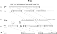
- FIG. 3 illustrates an exemplary packet configuration when the timed media is transmitted.
- FIG. 3(a) illustrates a video elementary stream (video ES).
- the video elementary stream is divided into clusters of a predetermined size which are arranged in a payload portion of an MMT fragment unit (MFU) as illustrated in FIG. 3(b) .
- MFU MMT fragment unit
- an MMT payload header is added to the MFU to constitute an MMTP payload. Then, as illustrated in FIG. 3(d) , the MMTP header (the MMT packet header) is further added to the MMTP payload to constitute the MMT packet.
- the MMT packet there is also an MMT packet in which a signaling message is included in a payload portion. As illustrated in FIG. 3(e) , a UDP header and an IP header are added to the MMT packet, so that the IP packet (IP packet) is generated. Although not illustrated, as the IP packet, there is also an IP packet including an MMT packet of other transmission media such as audio or captions.
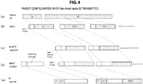
- FIG. 4 illustrates an exemplary packet configuration when the non-timed media is transmitted.
- FIG. 4(a) illustrates a file.
- Each of F1 and F2 indicates one file.
- F1 is a file used in a certain program
- F2 is a file used in a next program.
- the file of F1 Since the file of F1 has a small file size, the entire file of F1 is arranged in the payload of the MFU as illustrated in FIG. 4(b) .
- the file of F2 since the file of F2 has a large file size, the file of F2 is divided into a plurality of clusters, that is, a plurality of fragments, and each fragment is arranged in the payload of the MFU as illustrated in FIG. 4(b) .
- the MMT payload header is added to the MFU to constitute the MMTP payload.
- the MFU since the MFU having file data of F1 has a small size, the MFU is arranged in one MMTP payload.
- each of the MFUs having divisional data of F2-1, F2-2, and the like is arranged in one MMTP payload.
- the MMTP header (the MMT packet header) is further added to the MMTP payload to constitute the MMT packet.
- the MMT packet there is also an MMT packet in which a signaling message is included in a payload as illustrated in FIG. 4(d) .
- the UDP header and the IP header are added to the MMT packet, so that the IP packet is generated.
- FIG. 5(a) illustrates an exemplary configuration of the MMT packet.
- the MMT packet includes the MMTP header) and the MMTP payload.
- a 2-bit field of "V” indicates a version of an MMT protocol. According to a first edition of an MMT standard, this field is “00.”
- a 1-bit field of "C” indicates packet counter flag (packet_counter_flag) information and is “1" when there is a packet counter flag.
- a 2-bit field of "FEC” indicates an FEC type (FEC_type).
- a 1-bit field of "X” indicates extension header flag (extension_flag) information and is “1" when header extension of the MMT packet is performed. In this case, there is a field of "header_extension” which will be described later.
- a 1-bit field of "R” indicates RAP flag (RAP_flag) information and is “1” when the MMT payload transmitted through the MMT packet includes a head of a random access point.
- a 6-bit field of "type” is payload type (payload_type) information and indicates a data type of the MMTP payload. For example, “0x00” indicates that the payload is a Media Processing Unit (MPU), and “0x02" indicates that the payload is a signaling message.
- MPU Media Processing Unit
- 0x02 indicates that the payload is a signaling message.
- a 16-bit field of "packet_id” indicates a packet identifier (packet id) identifying a data type of the payload.
- a 32-bit field of "timestamp” indicates a type stamp for transmission, that is, a time at which the MMT packet is transmitted from the transmission side. This time is indicated in an NTP short format.
- a 32-bit field of "packet_sequence_number” indicates a sequence number of the MMT packet having the same packet identifier (packet_id).
- a 32-bit field of "packet counter” indicates an order of the MMT packet in the same IP data flow regardless of a value of the packet identifier (packet_id).
- FIG. 5 (b illustrates an exemplary configuration of the MMT extension header.
- a 16-bit field of "type” indicates a type of the extension header.
- a 16-bit field of "length” indicates a byte size of the extension header subsequent thereto. The byte size of the extension header differs according to the type of the extension header.
- a field of "header_extension_byte” indicates a data byte for header extension.
- FIG. 6(a) illustrates an exemplary configuration (syntax) of the MMTP payload arranged in the field of "payload data" of the MMT packet.
- This example indicates an MPU mode in which "type" of the MMT header is "0x00.”
- header information there is header information.
- a 16-bit field of "length” indicates a byte size of the entire MMTP payload.
- a 4-bit field of "FT” indicates a field type. "0” indicates that "MPU metadata” is included, “1” indicates that "Movie Fragment metadata” is included, and "2" indicates that "MFU” is included.
- the MFU is a unit obtained by subdividing the MPU into fragments.
- the MFU can be set to correspond to one NAL unit.
- the MFU may be configured with one or more MTU sizes.
- the MPU starts from a random access point and includes one or more access units (AUs). Specifically, for example, there are cases in which pictures of one Group Of Pictures (GOP) constitute one MPU.
- This MPU is defined according to an asset.
- a video MPU including only video data is generated from a video asset
- an audio MPU including only audio data is generated from an audio asset.
- 1-bit flag information of "T” indicates whether the timed media is transmitted, or the non-timed media is transmitted. “1” indicates the timed media, and “0” indicates the non-timed media.
- a 2-bit field of "f_i” indicates whether an integer number of data units (DUs) are included in a field of "DU payload” or any one of first, intermediate, and last fragments obtained by fragmenting a data unit is included in the field of "DU payload.” "0” indicates that an integer number of data units are included, “1” indicates that the first fragment is included, “2” indicates that the intermediate fragment is included, and “3” indicates that the last fragment is included.
- 1-bit flag information of "A” indicates whether or not a plurality of data units are included in the field of "DU payload.” "1” indicates that a plurality of data units are included in the field of "DU payload,” and “0” indicates that a plurality of data units are not included in the field of "DU payload.”
- An 8-bit field of "frag_counter” indicates an order of a fragment when "f_i" is 1 to 3.
- a 32-bit field of "MPU_sequence_number” is a number indicating an order of an MPU and serves as information identifying an MPU. For example, when one GOP constitutes one MPU, and "MPU_sequence_number" of a certain GOP is "i,” “MPU_sequence_number” of a next GOP is "i+1.”
- fields of "DU_length,” “DU_header,” and “DU_payload” are arranged.
- a 32-bit field of "movie_fragment_sequence_number” indicates a sequence number of an MFU unit. For example, when an I picture is divided, each one is an MFU.
- a 32-bit field of "sample_number” indicates, for example, a number of a picture unit in the case of a video.
- a 32-bit field of "offset” indicates, for example, an offset value (a byte value) from a head of a picture in the case of a video.
- a 32-bit field of "item_ID" is an ID identifying an item (file).
- the transmission media such as a video is transmitted in a content format based on a fragmented ISO Base Media File Format (ISOBMFF).
- ISOBMFF ISO Base Media File Format
- a configuration of the MMT file is basically substantially the same as a file MP4 configuration. First, an "ftyp” box is arranged. Subsequently, an "mmpu” box that is unique to the MMT is arranged. Subsequently, an "moov” box serving as metadata of the entire file is arranged.
- the movie fragment includes an "moof” box in which control information is included and an "mdat” box in which encoded data of a video is included.
- the movie fragment since one GOP is assumed to constitute one MPU, only one set of movie fragments is arranged.
- the metadata of the "ftyp,” “mmpu,” and “moov” boxes is transmitted as "MPU metadata" through one MMT packet.
- “FT” is "0.”
- the metadata of the "moof” box is transmitted as "Movie Fragment metadata” through one MMT packet.
- “FT” is "1.”
- the encoded data of the video included in the "mdat” box is fragmented into "MFUs,” and each MFU is transmitted through one MMT packet. In this case, "FT” is "2.”
- FIG. 8 illustrates an example of a correspondence relation between the MMT file and the MMTP payload when two items (files) are transmitted.
- a configuration of the MMT file is basically substantially the same as a file MP4 configuration.
- an "ftyp” box is arranged.
- an "mmpu” box that is unique to the MMT is arranged.
- "moov” and “meta” boxes serving as metadata of the entire file are arranged.
- "item #1" and “item #2” boxes in which an item (file) is included are arranged.
- the metadata of the "ftyp,” “mmpu,” “moov,” and “meta” boxes is transmitted as "MPU metadata" through one MMT packet.
- "FT" is "0.”
- Each of the items (files) included in the "item #1" and “item #2” boxes is transmitted through one MMT packet. In this case, "FT" is "2.”
- FIG. 9 illustrates a process flow of the receiver 200, that is, a process flow in a hybrid delivery.
- the receiver 200 selects a component to be presented according to a component layer model.
- the receiver 200 selects a component based on component selection information (the component layer model) inserted as signaling information.
- step ST2 the receiver 200 performs location solution of the selected component, and acquires a component.
- the receiver 200 acquires a component based on component acquisition destination information inserted as signaling information.
- step ST3 the receiver 200 performs synchronous reproduction of the selected component.
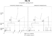
- FIG. 10 illustrates an example of the component layer model.
- the component layer model is a model in which component selection is performed based on a structure of three layers, that is, an adaptive layer, a composite layer, and a selective layer.
- the adaptive layer is a layer that is positioned at the bottom and adaptively switches a component.
- the composite layer is a layer that is positioned in the middle, performs signal composition, and generates another signal.
- the selective layer is a layer that is positioned on the top and selects a component to be finally presented. The respective layers will be further described.
- the selective layer is a layer that fixedly selects a component from a plurality of component choices in each component category by selection of the user or automatic selection of a terminal.
- the component category indicates a unit to be selected such as a video or audio.
- two categories of a video and an audio are illustrated.
- the following attributes are used.
- the composite layer is a layer that combines a plurality of components in each component category to function as one component.
- the selective layer When there is the selective layer above the composite layer, it indicates that the combined signal is regarded as one signal and selected in the selective layer.
- composition types and composition position information are used as attributes.
- the adaptive layer is a layer that dynamically switches a plurality of components based on adaptive determination of a terminal to function as one component.
- the following attributes are used.
- the component layer model illustrated in FIG. 10 indicates component selection information in each of the categories of a video and audio.
- the selective layer it is indicated that one or more components can be selected for each category.
- a composition process of components serving as choices in the selective layer is indicated. It is indicated that when there is only one component to be combined, the component is used as a choice in the selective layer without change.
- the adaptive layer the adaptive switching process of components used in the composite layer is indicated. It is indicated that when there is only one component to be switched, the component is constantly selected.
- the receiver 200 performs the component selection based on the component selection information (the component layer model) inserted as the signaling information.
- An exemplary component selection operation of the receiver 200 will be described.
- a component structure table is introduced so that the broadcast transmission system 110 transmits the component selection information (the component layer model) to the receiver 200.
- a CST is newly introduced into a package access (PA) message of signaling together with an MMT package table (MPT), and thus a 3-layer model of component selection in a broadcasting/communication hybrid multi-component configuration is implemented.
- PA package access
- MPT MMT package table
- each component is identified by a component tag (component_tag) and linked with an asset description (component description) of the MPT.
- component_tag component tag
- asset description component description
- the CST describes a component configuration such as an integrated component corresponding to the selective layer for each component category such as a video or audio and an atomic component corresponding to the composite/adaptive layer for each integrated component, and provides a parameter necessary for selection in each layer through various descriptors.
- parameters and descriptors of the respective layers of the CST are as follows.
- the parameter of the default selection policy indicates, for example, any one of application selection, resident automatic selection, resident UI selection, and non-designation.
- parameters of this layer there are parameters of a category type and a component selection policy.
- the parameter of the category type indicates a video, audio, captions, or the like.
- the parameter of the component selection policy indicates any one of application selection, resident automatic selection, resident UI selection, and non-designation.
- parameters of this layer there are parameters of an integrated component identifier, combination information with other component categories, and configuration information of the atomic component.
- the parameter of the configuration information of the atomic component indicates whether or not an atomic component of a composite/adaptive target is included.
- parameters of a default selected integrated component there are parameters of a default selected integrated component, an integrated component having a high priority at the time of emergency, and a CA type.
- the parameter of the CA type indicates combination information of paid/free and encryption/non-encryption in the integrated component.
- an integrated video component descriptor As descriptors of this layer, there are an integrated video component descriptor, an integrated audio component descriptor, a target device descriptor, a target region descriptor, a view point descriptor, and a parental rating descriptor.
- the integrated video component descriptor indicates selection information of a video component, for example, the resolution or the like.
- the integrated audio component descriptor indicates selection information of an audio component, for example, a channel configuration or the like.
- the target device descriptor designates a presentation target device of the integrated component.
- the target region descriptor designates a use target region of the integrated component.
- the view point descriptor indicates a view point identification of the integrated component.
- the parental rating descriptor indicates rating information.
- parameters of this layer there are parameters of an atomic component identifier and an atomic component type.
- the parameter of the atomic component identifier is a component tag.
- the parameter of the atomic component type indicates any one of adaptive, composite, and (adaptive+composite).
- the adaptive switch descriptor indicates information necessary for adaptive switching such as a priority or a rate.
- the composite component type descriptor indicates a composite component type or the like.
- FIG. 11 illustrates a correspondence relation between the adaptive layer, the composite layer, and the adaptive layer in the component layer model and the integrated component and the atomic component in the CST.
- FIG. 11 illustrates that the asset description (component description) of the MPT is linked with the component of the CST.
- FIG. 12 illustrates an example of a signal configuration assumed in the broadcasting/communication hybrid system 10 of FIG. 1 .
- a video 1 Video1
- audio 1 Audio 1
- audio 2 Audio2
- Caption Caption
- signaling there is the PA message, and the tables such as the MPT and the CST are inserted into the PA message.
- a video 2 (Video2) and audio 3 are transmitted using the MMT packet
- a video 3 Video3) and audio 4 (Audio4) are transmitted using an HTTP packet.
- the MPT will be described.
- the MMT packet as described above, there is also an MMT packet in which a signaling message is included in a payload.
- a PA message including the MPT.
- the MPT indicates a component (asset) that constitutes one broadcast service.
- FIG. 13 schematically illustrates exemplary configurations of the PA message and the MPT.
- FIG. 14 illustrates a description of main parameters of the PA message
- FIG. 15 illustrates a description of main parameters of the MPT.
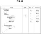
- “message_id” is a fixed value identifying the PA message in various kinds of signaling information. "version” is an 8-bit integer value indicating a version of the PA message. For example, when some parameters constituting the MPT are updated, it is incremented by +1. "length” is the number of bytes indicating the size of the PA message which is counted directly after this field.
- index information of a table arranged in a payload field is arranged.
- fields of "table_id,” “table_version,” and “table_length” are arranged by the number of tables.
- table_id is a fixed value identifying a table.
- table_version indicates a version of a table.
- table_length is the number of bytes indicating the size of a table.
- the MPT and a predetermined number of other tables are arranged.
- a configuration of the MPT will be described.
- table_id is a fixed value identifying the MPT in various kinds of signaling information.
- version is an 8-bit integer value indicating a version of the MPT. For example, when some parameters constituting the MPT are updated, it is incremented by +1.
- length is the number of bytes indicating the size of the MPT which is counted directly after this field.
- Pack_id is identification information of the entire package in which all signals and files transmitted through a broadcast signal are set as components.
- the identification information is text information.
- Pack_id_len indicates the size of the text information (the number of bytes).
- An “MPT_descripors” field is a storage region of a descriptor related to the entire package.
- MPT_dsc_len indicates the size of the field (the number of bytes).
- number_of_asset indicates the number of assets (signals and files) serving as an element constituting a package.
- the following asset loops are arranged according to the number.
- assert_id is information (an asset ID) identifying an asset uniquely.
- the identification information is text information.
- assert_id_len indicates the size of the text information (the number of bytes).
- gen_loc_info is information indication a location of an asset acquisition destination.
- An “asset_descriptors” field is a storage region of a descriptor related to an asset.
- assert_dsc_len indicates the size of the field (the number of bytes).
- FIG. 16 illustrates an exemplary structure (syntax) of the PA message.
- FIG. 17 illustrates an exemplary structure (syntax) of the MPT.
- FIG. 18 to FIG. 20 illustrate an exemplary structure (syntax) of the CST.
- table_id is a fixed value identifying the CST in various kinds of signaling information.
- version is an 8-bit integer value indicating a version of the CST. For example, when some parameters constituting the CST are updated, it is incremented by +1.
- length is the number of bytes indicating the size of the CST which is counted directly after this field.
- a 4-bit field of "default_selection_policy” indicates a default selection policy.
- the "default_selection_policy” indicates how the component selection related to the selective layer is performed. For example, “0” indicates that the selection is performed through an application of HTML 5, “1” indicates that the selection is performed by the user using the GUI, and “2" indicates that the selection is automatically performed by the terminal (the receiver).
- the component selection is roughly divided into two selections, that is, the application selection and the resident selection.
- the application selection indicates selection by an application (software) provided by a broadcaster
- the resident selection indicates selection by software specific to the receiver.
- the resident selection is performed such that automatic selection is performed, that is, selection is automatically performed by the receiver according to the attribute or such that the choices are displayed and selected by the user.
- the application selection is performed in one of two methods, that is, either selection is automatically performed by an application or choices are displayed and selected by the user, but it is not particularly distinguished since both two methods are included in a range expressed in an application.
- An 8-bit field of "no_of_component_category" indicates the number of component categories.
- the category is a video, audio, or the like.
- a part subsequent to this field is a for loop and indicates information of each component category.
- a 4-bit field of "category_type” indicates a category type such as a video or audio.
- a 4-bit field of "component_selection_policy” indicates a component selection policy. A selection policy of each component category can be set through this field. If “default_selection_policy” is acceptable, following “default_selection_policy” is indicated by setting the same values or either of all “1s” and all “0s” as a value of "component_selection_policy.”
- An 8-bit field of "no_of_integrated_component" indicates the number of integrated components. A part subsequent to this field is a for loop and indicates information of each integrated component.
- An 8-bit field of "integrated component id” indicates an identifier (ID) of the integrated component.
- An 8-bit field of "combination_tag” indicates a combination tag serving as an identifier of a combination selected through the category crossing.
- a 1-bit field of "composite_flag” indicates a composition flag. For example, “1” indicates that composition of the atomic component is included.
- a 1-bit field of "adaptive_flag” indicates an adaptive switching flag. For example, "1" indicates that adaptive switching of the atomic component is included.
- a 1-bit field of "default_flag” is a default flag indicating whether or not it is a default selection target. For example, “1" indicates a default selection target.
- a 1-bit field of "emergency_flag” indicates whether or not it is an integrated component for emergency. For example, “1” indicates an integrated component for emergency.
- a 2-bit field of "conditional_access_type” is a conditional access flag indicating paid/free and encryption/non-encryption. In this case, for example, one of two bits indicates paid/free, and the remaining one bit indicates encryption/non-encryption.
- An "integrated_comp_descriptors_byte” field is a description region for the integrated component.
- a 16-bit field of "integrated_comp_descriptors_length” indicates the size of the description region for the integrated component.
- a level of the integrated component, that is, various parameters necessary for selection in the selective layer are embedded in the description region for the integrated component as a descriptor.
- An 8-bit field of "no_of_atomic_component” indicates the number of atomic components (unit components) expanded under the integrated component. For example, in FIG. 10 , each component described in the adaptive layer is the atomic component. A part subsequent to this field is a for loop and indicates information of each atomic component.
- a 16-bit field of "component_tag” indicates a component tag. Through this component tag, the atomic component is linked with an asset description (component description) of the MPT.
- a 2-bit field of "atomic_component_type” indicates a type of atomic component.
- "00" indicates a "single” type.
- the "single” type indicates an atomic component that is subject to neither the adaptive switching in the adaptive layer nor the composition with other components in the composite layer but becomes an integrated component without change.
- a component indicated by an arrow a corresponds to this type.
- "01" indicates a "composite” type.
- the "composite” type indicates an atomic component that is subject to the composition with other components in the composite layer and becomes an integrated component without being subject to the adaptive switching in the adaptive layer.
- a component indicated by an arrow b corresponds to this type.
- “10” indicates an “adaptive” type.
- the "adaptive” type indicates an atomic component that becomes an integrated component without change without being subject to the composition with other components in the composite layer when it is selected by the adaptive switching in the adaptive layer.
- a component indicated by an arrow c corresponds to this type.
- "11" indicates a “composite+adaptive” type.
- the "composite+adaptive” type indicates an atomic component that is subject to the composition with other components in the composite layer and becomes an integrated component when it is selected by the adaptive switching in the adaptive layer.
- a component indicated by an arrow d corresponds to this type.
- An "atomic_comp_descriptors_byte” field is a descriptor region for the atomic component.
- An 8-bit field of "atomic_comp_descriptors_length” indicates the size of the descriptor region for the atomic component.
- a level of the atomic component that is, various parameters necessary for selection and composition in the adaptive layer and in the composite layer, are embedded in the descriptor region for the atomic component as a descriptor.
- the descriptor embedded in the description region for the integrated component that is, the integrated component descriptor
- the integrated component descriptor the integrated video component descriptor, the integrated audio component descriptor, the target device descriptor, the target region descriptor, the view point descriptor, and the parental rating descriptor are assumed.
- the integrated video component descriptor is a descriptor describing selection information related to a video such as a resolution, a frame rate, and a 3D parameter.
- the integrated audio component descriptor is a descriptor describing selection information related to an audio such as multichannel and sampling frequency.
- the target device descriptor is a descriptor describing device information of a target that reproduces a corresponding component.
- the target region descriptor is a descriptor describing information indicating a region of a target that reproduces a corresponding component.
- the view point descriptor is a descriptor describing meta information related to a view of a video.
- the parental rating descriptor is a descriptor describing rating information of a corresponding component.
- FIG. 21 illustrates an exemplary structure (syntax) of the integrated video component descriptor.
- a 16-bit field of "descriptor_tag” indicates a descriptor tag.
- “descriptor_tag” indicates the integrated video component descriptor.
- An 8-bit field of "descriptor_length” indicates a descriptor length and indicates the number of bytes subsequent to this field.
- a 1-bit field of "basic_format_flag” is a basic format flag and indicates whether or not there is a description of a basic format. For example, “1” indicates that there is a description of a basic format.
- a 1-bit field of "3D_format_flag” is a 3D format flag and indicates whether or not there is a description of a 3D format. For example, "1" indicates that there is a description of a 3D format.
- a 1-bit field of "language_code_flag” is a language flag and indicates whether or not there is a description of a language. For example, “1" indicates that there is a description of a language.
- a 1-bit field of "specific_video_flag” is a specific video flag, and indicates whether or not there is a description of a specific video type. For example, "1" indicates that there is a description of a specific video type.
- basic-format flag When “basic-format flag” is "1,” there is a description of a basic format as follows.
- a 4-bit field of “video_resolution” indicates the resolution in the vertical direction. For example, “1” indicates “180,” “2” indicates “240,” “3” indicates “480,” “4" indicates “720,” “5" indicates “1080,” “6” indicates “2160,” and “7” indicates “4320.”
- a 4-bit field of "video_aspect_ratio” indicates an aspect ratio. For example, “1” indicates “4:3,” “2” indicates “16:9 with a pan vector (PV),” “3” indicates “16:9 with no PV,” and “4" indicates “16:9 or more.”
- a 1-bit field of "video_scan_flag” indicates a scan flag. For example, “0” indicates interlaced, and "1" indicates progressive.
- a 5-bit field of "video_frame_rate” indicates a frame rate. For example, “4" indicates “25 frames,” “5" indicates “30/1.001 frames,” “6” indicates “30 frames,” “7” indicates “50 frames,” “8” indicates “60/1.001 frames,” and “9” indicates “60 frames.”
- 3D_format_flag When “3D_format_flag” is "1,” there is a description of a 3D format type.
- An 8-bit field of “3D_format_type” indicates a 3D format type. For example, “1” indicates “stereo/side by side scheme,” and “2" indicates a “stereo/top and bottom scheme.”
- FIG. 22 illustrates an exemplary structure (syntax) of the integrated audio component descriptor.
- a 16-bit field of "descriptor_tag” indicates a descriptor tag.
- “descriptor_tag” indicates the integrated audio component descriptor.
- An 8-bit field of "descriptor_length” indicates a descriptor length and indicates the number of bytes subsequent to this field.
- a 1-bit field of "basic_format_flag” is a basic format flag and indicates whether or not there is a description of a basic format. For example, “1” indicates that there is a description of a basic format.
- a 1-bit field of "language_code_flag” is a language flag and indicates whether or not there is a description of a language. For example, “1” indicates that there is a description of a language.
- a 1-bit field of "specific_audio_flag” is a specific audio flag and indicates whether or not there is a description of a specific audio type. For example, "1” indicates that there is a description of a specific audio type.
- a 1-bit field of "ES_multi-lingual_flag” indicates an ES multi-lingual flag. For example, “1” indicates that two-language multiplexing is performed in a dual mono.
- a 1-bit field of "robust_level” indicates a level of robustness. For example, “0” indicates normal robustness, and “1” indicates high robustness.
- basic_format_flag When “basic_format_flag” is "1,” there is a description of a basic format as follows.
- An 8-bit field of “multichannnel_mode” indicates a multichannel mode. For example, “1” indicates “single mono,” “2” indicates “dual mono,” and “17” indicates “22.2 channels.”
- a 2-bit field of "quality_indicator” indicates an audio quality indicator. For example, “1” indicates “mode 1,” “2” indicates “mode 2,” and “3” indicates “mode 3.”
- a 3-bit field of "sampling_rate” indicates a sampling frequency. For example, “1” indicates “16 kHz,” “2” indicates “22.05 kHz,” “3” indicates “24 kHz,” “5" indicates “32 kHz,” “6” indicates “44.1 kHz,” and "7” indicates “48 kHz.”
- FIG. 23 illustrates an exemplary structure (syntax) of the target device descriptor.
- a 16-bit field of "descriptor_tag” indicates a descriptor tag.
- “descriptor_tag” indicates the target device descriptor.
- An 8-bit field of "descriptor_length” indicates a descriptor length and indicates the number of bytes subsequent to this field.
- An 8-bit field of "number_of_taget_device” indicates the number of target devices.
- For each target device there is an 8-bit field of "target_device_type” which indicates a target device type.
- target_device_type indicates a type such as a television with a large screen, a tablet with a small screen, or a smart phone with a smaller screen.
- FIG. 24 illustrates an exemplary structure (syntax) of the target region descriptor.
- a 16-bit field of "descriptor_tag” indicates a descriptor tag.
- “descriptor_tag” indicates the target region descriptor.
- An 8-bit field of "descriptor_length” indicates a descriptor length and indicates the number of bytes subsequent to this field.
- region_spec_type indicates a region description method designation. For example, "1" indicates a prefectural region designation.
- a region designator (region designation data) by a designated description method is described in a "target_region_spec ()" field.
- FIG. 25 illustrates an exemplary structure (syntax) of the view point descriptor.
- a 16-bit field of "descriptor_tag” indicates a descriptor tag.
- “descriptor_tag” indicates the view point descriptor.
- An 8-bit field of "descriptor_length” indicates a descriptor length and indicates the number of bytes subsequent to this field.
- An 8-bit field of "view_tag” indicates a view tag serving as identification information of video content. There are cases in which the video content is the same, but a rate and a codec are different. When the view tag is the same, it indicates that the video content is the same. Character string data of a view name serving as a name of video content is arranged in a "view_name_byte" field.
- FIG. 26 illustrates an exemplary structure (syntax) of the parental rating descriptor.
- a 16-bit field of "descriptor_tag” indicates a descriptor tag.
- “descriptor_tag” indicates the parental rating descriptor.
- An 8-bit field of "descriptor_length” indicates a descriptor length and indicates the number of bytes subsequent to this field.
- a rating can be designated for each country.
- a 24-bit field of "country_code” indicates a country code.
- An 8-bit field of “rating” indicates a rating. "rating+age of 3" indicates a minimum age.
- the adaptive switch descriptor and the composite component type descriptor are assumed as the atomic component descriptor.
- the adaptive switch descriptor is a descriptor describing selection information for adaptively switching the atomic component.
- the composite component type descriptor is a descriptor describing information indicating a composite component obtained by combining a plurality of atomic components and a type of composition.
- FIGS. 27 and 28 illustrate an exemplary structure (syntax) of the adaptive switch descriptor.
- a 16-bit field of "descriptor_tag” indicates a descriptor tag.
- “descriptor_tag” indicates the adaptive switch descriptor.
- An 8-bit field of "descriptor_length” indicates a descriptor length and indicates the number of bytes subsequent to this field.
- a 3-bit field of "path_type” indicates a transmission type. For example, “0" indicates broadcasting, “1” indicates communication (MMT/IP multicast), “2” indicates communication (MMT/UDP/IP), “3” indicates communication (MMT/TCP/IP), and “4" indicates communication (HTTP).
- a 1-bit field of "default_flag” indicates a default flag. For example, “1” indicates that the atomic component is selected by default, that is, is initially selected.
- a 1-bit field of "priority_indicator flag” indicates a priority designation flag. For example, “1" indicates that there is a priority designation description.
- a 1-bit field of "bitrate_flag” indicates a bit rate flag. For example, "1" indicates that there is a bit rate description.
- a 1-bit field of "video_format_flag” indicates a video format flag. For example, “1” indicates that there is a video format description.
- a 1-bit field of "audio_format_flag” indicates an audio format flag. For example, "1" indicates that there is an audio format description.
- priority_indicator_flag When “priority_indicator_flag” is “1,” there is a description of a priority designation.
- An 8-bit field of “priority_indicator” indicates a priority designation. In this case, a large value indicates a high priority. As a priority increases, a higher quality and a wider band are required.
- bitrate_flag When “bitrate_flag” is “1,” there is a description of a bit rate.
- a 16-bit rate of "bitrate” indicates a bit rate, for example, using units of 10 kbps.
- video_format_flag When "video_format_flag” is "1," there is a description of a video format as follows.
- a 4-bit field of “video_resolution” indicates a resolution.
- a 4-bit field of "video_aspect_ratio” indicates an aspect ratio.
- a 1-bit field of "video_scan_flag” indicates a scan flag.
- a 5-bit field of "video_frame_rate” indicates a frame rate.
- audio_format_flag When “audio_format_flag” is "1," there is a description of an audio format as follows.
- An 8-bit field of “multichannnel_mode” indicates a multichannel mode.
- a 2-bit field of “quality_indicator” indicates a quality indicator.
- a 3-bit field of "sampling_rate” indicates a sampling rate.
- a 1-bit field of "robust_level” indicates a level of robustness. For example, “0” indicates normal robustness, and "1" indicates high robustness.
- FIG. 29 illustrates an exemplary structure (syntax) of the composite component type descriptor.
- a 16-bit field of "descriptor_tag” indicates a descriptor tag.
- “descriptor_tag” indicates the composite component type descriptor.
- An 8-bit field of "descriptor_length” indicates a descriptor length and indicates the number of bytes subsequent to this field.
- Composite_component_type indicates a composite component type.
- composite_component_type indicates a type such as scalable, 3D, tile, layer, or mixing.
- a 1-bit field of "dependency_flag” indicates a dependency flag. For example, “1” indicates that it is a component depending on another component. When “dependency_flag” is "1,” there is a 16-bit field of "dependent_component_tag.” This field indicates a dependent target component tag.
- FIG. 30 indicates a specific example of an association between the MPT and the CST. This example corresponds to the signal configuration of FIG. 12 .
- each integrated component there is various information including the integrated component descriptor (I.Comp Descriptors), and there is various information including the atomic component descriptor (A.Comp Descriptors) of the atomic component expanded under this integrated component.
- I.Comp Descriptors integrated component descriptors
- A.Comp Descriptors atomic component descriptors
- an atomic component expanded under a first integrated component is a video 1 (Video 1) that is transmitted in a broadcasting manner.
- I.Comp Descriptors integrated component descriptors
- A.Comp Descriptors atomic component descriptors
- atomic components expanded under a first integrated component are audio 1 (Audio 1) and audio 2 (Audio2) that are transmitted in a broadcasting manner.
- An atomic component expanded under a second integrated component is audio 3 (Audio3) that is transmitted in a communication manner.
- An atomic component expanded under a third integrated component is audio 4 (Audio4) that is transmitted in a communication manner.
- captions there is one integrated component.
- this integrated component there is various information including the integrated component descriptor (I.Comp Descriptors), and there is various information including the atomic component descriptor (A.Comp Descriptors) of the atomic component expanded under this integrated component.
- an atomic component is captions 1 (Caption1) that are transmitted in a broadcasting manner.
- each asset there is a description of each asset (component).
- information indicating a location of an acquisition destination is inserted into a "General_Location_info ()" field.
- Each atomic component of the CST is associated with a corresponding asset description of the MPT using a component tag (Component). Accordingly, it is possible to recognize the acquisition destination in the MPT and acquire each atomic component.
- FIG. 31 illustrates an exemplary configuration of the broadcast transmission system 110.
- the broadcast transmission system 110 includes a clock unit 111, a signal transmitting unit 112, a video encoder 113, an audio encoder 114, a caption encoder 115, a signaling generator 116, and a file encoder 117.
- the broadcast transmission system 100 further includes a TLV signaling generator 118, N IP service multiplexers 119-1 to 119-N, a TLV multiplexer 120, and a modulating/transmitting unit 121.
- the clock unit 111 generates time information (NTP time information) synchronized with time information acquired from an NTP server (not illustrated), and transmits an IP packet including the time information to the IP service multiplexer 119-1.
- the signal transmitting unit 112 is a studio of a TV station or a recording/reproducing device such as a VTR, and transmits stream data such as a video, audio, or captions serving as the timed media or a file (file data) such as HTML document data serving as the non-timed media to the respective encoders.
- the video encoder 113 encodes a video signal transmitted from the signal transmitting unit 112, packetizes the encoded signal, and transmits the IP packet including the MMT packet of the video to the IP service multiplexer 119-1.
- the audio encoder 114 encodes an audio signal transmitted from the signal transmitting unit 112, packetizes the encoded signal, and transmits the IP packet including the MMT packet of the audio to the IP service multiplexer 119-1.
- the caption encoder 115 encodes a caption signal transmitted from the signal transmitting unit 112, packetizes the encoded signal, and transmits the IP packet including the MMT packet of the caption to the IP service multiplexer 119-1.
- the file encoder 117 combines or divides the file (file data) transmitted from the signal transmitting unit 112 as necessary, generates the MMT packet including the file, and transmits the IP packet including the MMT packet to the IP service multiplexer 119-1.
- the signaling generator 116 generates a signaling message, and transmits the IP packet including the MMT packet in which the signaling message is arranged in the payload portion to the IP service multiplexer 119-1. In this case, the signaling generator 116 arranges the CST in the PA message together with the MPT (see FIGS. 13 to 20 ).
- the IP service multiplexer 119-1 performs time-division multiplexing on the IP packets transmitted from the respective encoders. At this time, the IP service multiplexer 119-1 generates TLV packets by adding the TLV header to the IP packets.
- the IP service multiplexer 119-1 constitutes one channel part included in one transponder.
- the IP service multiplexers 119-2 to 119-N have the same function as the IP service multiplexer 119-1 and constitute other channel parts included in one transponder.
- the TLV signaling generator 118 generates signaling information, and generates a TLV packet in which the signaling information is arranged in a payload portion.
- the TLV multiplexer 120 multiplexes the TLV packets generated by the IP service multiplexers 119-1 to 119-N and the TLV signaling generator 118, and generates a broadcast stream.
- the modulating/transmitting unit 121 performs an RF modulation process on the broadcast stream generated by the TLV multiplexer 120, and transmits a resulting stream to an RF transmission path.
- the clock unit 111 generates the time information synchronized with the time information acquired from an NTP server, and generates the IP packet including the time information.
- the IP packet is transmitted to the IP service multiplexer 119-1.
- the video signal transmitted from the signal transmitting unit 112 is supplied to the video encoder 113.
- the video encoder 113 encodes the video signal, packetizes the encoded signal, and generates the IP packet including the MMT packet of the video.
- the IP packet is transmitted to the IP service multiplexer 119-1.
- a similar process is performed on the audio signal transmitted from the signal transmitting unit 112. Then, the IP packet including the MMT packet of the audio generated by the audio encoder 114 is transmitted to the IP service multiplexer 119-1.
- the file transmitted from the signal transmitting unit 112 is supplied to the file encoder 117.
- the file encoder 117 combines or divides the file as necessary, generates the MMT packet including the file, and further generates the IP packet including the MMT packet.
- the IP packet is transmitted to the IP service multiplexer 119-1.
- a similar process is performed on the audio signal and the caption signal transmitted from the signal transmitting unit 112. Then, the IP packet including the MMT packet of the audio generated by the audio encoder 114 is transmitted to the IP service multiplexer 119-1, and the IP packet including the MMT packet of the caption generated by the caption encoder 115 is transmitted to the IP service multiplexer 119-1.
- the signaling generator 116 generates the signaling message, and generates the IP packet including the MMT packet in which the signaling message is arranged in the payload portion.
- the IP packet is transmitted to the IP service multiplexer 119-1.
- the CST is arranged in the PA message together with the MPT.
- the IP service multiplexer 119-1 performs time-division multiplexing on the IP packets transmitted from the respective encoders and the signaling generator 116. At this time, the TLV header is added to the IP packets to generate the TLV packets.
- the IP service multiplexer 119-1 processes one channel part included in one transponder, and the IP service multiplexers 119-2 to 119-N similarly process other channel parts included in one transponder.
- the TLV packets obtained by the IP service multiplexers 119-1 to 119-N are transmitted to the TLV multiplexer 120.
- the TLV packet in which the signaling information is arranged in the payload portion is also transmitted from the TLV signaling generator 118 to the TLV multiplexer 120.
- the TLV multiplexer 120 multiplexes the TLV packets generated by the IP service multiplexers 119-1 to 119-N and the TLV signaling generator 118, and generates the broadcast stream.
- the broadcast stream is transmitted to the modulating/transmitting unit 121.
- the modulating/transmitting unit 121 performs the RF modulation process on the broadcast stream, and transmits the RF modulated signal to the RF transmission path.
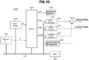
- FIG. 32 illustrates an exemplary configuration of the receiver 200.
- the receiver 200 includes a CPU 201, a tuner/demodulating unit 202, a network interface unit 203, a demultiplexer 204, and a system clock generator 205.
- the receiver 200 further includes a video decoder 206, an audio decoder 207, a caption decoder 208, an application display data generator 209, and a combining unit 210.
- the CPU 201 constitutes a control unit, and controls operations of the respective units of the receiver 200.
- the tuner/demodulating unit 202 receives the RF modulated signal, performs a demodulation process, and obtains a broadcast stream.
- the network interface unit 203 receives a transmission stream of a service delivered from the delivery server 120 via the communication network 300.
- the demultiplexer 204 performs a demultiplexing process and a depacketization process on the broadcast stream obtained by the tuner/demodulating unit 202 and the transmission stream obtained by the network interface unit 203, and outputs the NTP time information, the signaling information, the encoded video and audio signals, and the file (file data).
- the file constitutes data broadcast content.
- the system clock generator 205 generates a system clock STC synchronized with the time information based on the NTP time information obtained by the demultiplexer 204.
- the video decoder 206 decodes the encoded video signal obtained by the demultiplexer 204, and obtains a baseband video signal.
- the audio decoder 207 decodes the encoded audio signal obtained by the demultiplexer 204, and obtains a baseband audio signal.
- the caption decoder 208 decodes the encoded caption signal obtained by the demultiplexer 204, and obtains a caption display signal.
- the application display data generator 209 obtains a data broadcast display signal based on the file (file data) obtained by the demultiplexer 204 under control of the CPU 201. Files of the same content are repeatedly transmitted through the broadcast stream.
- the CPU 201 controls a filtering operation in the demultiplexer 204 such that the demultiplexer 204 acquires only a necessary file.
- the CPU 201 controls decoding timings of the respective decoders based on a presentation timestamp (PTS) (presentation time information) such that video and audio presentation timings are adjusted.
- PTS presentation timestamp
- the combining unit 210 combines the baseband video signal obtained by the video decoder 206 with the caption display signal and the data broadcast display signal, and obtains a video signal for video display. An audio signal for audio output is obtained based on the baseband audio signal obtained by the audio decoder 207.
- the tuner/demodulating unit 202 receives the RF modulated signal transmitted via the RF transmission path, performs the demodulation process, and obtains the broadcast stream.
- the broadcast stream is transmitted to the demultiplexer 204.
- the network interface unit 203 receives the transmission stream of the service delivered from the delivery server 120 via the communication network 300, and transmits the transmission stream to the demultiplexer 204.
- the demultiplexer 204 performs the demultiplexing process and the depacketization process on the broadcast stream transmitted from the tuner/demodulating unit 202 and the transmission stream transmitted from the network interface unit 203, and extracts the NTP time information, the signaling information, the video and audio encoded signals, and the file (file data) constituting the data broadcast content.
- the signaling information includes TLV-SI and MMT-SI.
- the TLV-SI is the transmission control signal (TLV-NIT/AMT) arranged above the TLV transmission packet
- the MMT-SI is the signaling message serving as the signaling information included in the payload portion of the MMT packet (see FIG. 2 ).
- the CPU 201 controls the operations of the respective units of the receiver 200 based on the signaling information.
- the NTP time information extracted by the demultiplexer 204 is transmitted to the system clock generator 205.
- the system clock generator 205 generates the system clock STC synchronized with the time information based on the NTP time information.
- the system clock STC is supplied to the video decoder 206, the audio decoder 207, and the caption decoder 208.
- the encoded video signal extracted by the demultiplexer 204 is transmitted to and decoded by the video decoder 206, so that the baseband video signal is obtained.
- the encoded caption signal extracted by the demultiplexer 204 is transmitted to and decoded by the caption decoder 208, so that the caption display signal is obtained.
- the file extracted by the demultiplexer 204 is transmitted to the CPU 201 via the CPU bus 211.
- the CPU 201 analyzes the file, performs a layout process and a rendering process, and instructs the application display data generator 209 to generate display data.
- the application display data generator 209 generates the data broadcast display signal based on the instruction.
- the video signal obtained by the video decoder 206 is supplied to the combining unit 210.
- the caption display signal obtained by the caption decoder 208 is supplied to the combining unit 210.
- the display signal generated by the application display data generator 209 is supplied to the combining unit 210.
- the combining unit 210 combines the signals, and obtains the video signal for video display.
- the encoded audio signal extracted by the demultiplexer 204 is transmitted to and decoded by the audio decoder 206, so that the baseband audio signal for audio output is obtained.
- the receiver 200 selectively acquires the transmission media (component) such as a video and audio to be presented from the reception signal by the broadcasting/communication hybrid transmission based on the component selection information (the component layer model) included in the broadcast signal, that is, the CST arranged in the PA message, and presents an image, audio, and the like.
- component the component layer model
- the receiver 200 (the CPU 201) analyzes the CST. In order to select the integrated component in the video component category, the receiver 200 displays the GUI for selection of the user as necessary based on the information such as the descriptor (I.Comp Descriptors) of the integrated component, and allows the user to make a selection.
- the descriptor I.Comp Descriptors
- FIG. 33(a) illustrates an example of a component selection GUI.
- the GUI is for allowing the user to perform view selection, language selection, and handicap selection.
- FIG. 33(b) when a view button 401 on the GUI is operated, a drop-down menu for view selection is displayed, and the user can select any one of "display all views,” “main,” “sub 1,” and "sub 2.”
- a language button 402 on the GUI when a language button 402 on the GUI is operated, a drop-down menu for language selection is displayed, and the user can select any one of, "Japanese,” “English,” “Chinese,” and “Korean.”
- a handicap button 401 on the GUI when a handicap button 401 on the GUI is operated, a drop-down menu for handicap selection is displayed, and the user can select any one of "vision-impaired person” and "hearing-impaired person.”
- the receiver 200 automatically selects one or more integrated components according to a capability or a setting. At the time of tuning or at the time of power-on, the receiver 200 automatically selects a default integrated component default component.
- the receiver 200 determines the atomic component that is subject to composition and adaptive switching based on information such as the atomic component descriptor (A.Comp Descriptors).
- the receiver 200 determines an asset having a corresponding component tag from the CST with reference to the MPT based on the component tag of the atomic component. Then, the receiver 200 recognizes the acquisition destination (the MMT packet of broadcasting/communication and the file on the communication network) designated by the "General location Info ()" field of the asset description of the MPT, and acquires and reproduces signal data.
- acquisition destination the MMT packet of broadcasting/communication and the file on the communication network
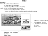
- the use case is a multiview example as illustrated in FIG. 34 .
- one program is configured of three pieces of "video+audio," that is, main view/sub view 1/sub view 2.
- the main view video is a video displayed when tuning is performed by default, and a video with a resolution (4K) of 3840*2160 or a resolution (2K) of 1920*1080 is assumed to be automatically selected according to a capability of the receiver.
- 4K scalable coding of combining a 2K video signal (base) and a differential signal (extended) is performed.
- the 2K video signal is transmitted in a broadcasting manner, but the differential signal is transmitted via a network while adaptively switching several rates by adaptive streaming.
- 22.2 ch or a stereo is assumed to be automatically selected according to a capability and a connection environment of the receiver.
- scalable coding of combining a stereo signal (base) with a differential signal (extended) is performed.
- base base
- differential signal extended
- two broadcasting systems and one streaming system are assumed to be adaptively switched according to a broadcast reception environment.
- the differential signal is delivered via a network in a streaming manner.
- each of a video signal and an audio signal is delivered via a network through one system.
- a video signal is a 2K video signal
- an audio signal is a stereo signal.
- signals with several rates and resolutions are adaptively switched and delivered via a network as a video signal, and an audio signal is delivered via a network through one system.
- a video signal is a 2K video signal
- an audio signal is a stereo signal.
- FIG. 35 illustrates a component layer model corresponding to the multiview example.
- the component category there are a video and audio. It is indicated that, in the selective layer of the video, a 4K video signal or a 2K video signal can be selected as a main view, and a sub 1 view and a sub view 2 can be selected.
- the main view (the 4K video signal) serving as a choice in the selective layer is encoded by the scalable coding, and is a composition signal obtained by combining the base signal (the 2K video signal) transmitted in a broadcasting manner with the extended signal (the differential signal) obtained by adaptively switching a plurality of signals transmitted in a communication manner.
- the main view (the 2K video signal) serving as a choice in the selective layer is the base signal (the 2K video signal) transmitted in a broadcasting manner.
- the sub view 1 serving as a choice in the selective layer is a video signal transmitted in a communication manner.
- the sub view 2 serving as a choice in the selective layer is a video signal obtained by adaptively switching a plurality of video signals transmitted in a communication manner.
- the 22.2 ch signal or the stereo signal can be selected as the main view, and the sub 1 view and the sub view 2 can be selected.
- the main view (the 22.2 ch signal) serving as a choice in the selective layer is one encoded by scalable coding, and is a composition signal of the stereo signal obtained by adaptively switching the signals transmitted through two broadcasting systems and one communication system and the differential signal transmitted in a communication manner.
- the main view (the stereo signal) serving as a choice in the selective layer is one encoded by scalable coding, and is the stereo signal transmitted in a broadcasting manner. It is indicated that, in the composite layer and the adaptive layer of the audio, each of the sub view 1 and the sub view 2 serving as a choice in the selective layer is the stereo signal transmitted in a communication manner.
- the respective views are combined using the combination tag and are selected through the category crossing.
- the main view, the sub view 1, and the sub view 2 of the video are selected.
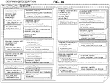
- FIG. 36 illustrates a description example of the CST corresponding to the multiview example.
- "default_selection_policy” is set to "1,” and it is indicated that the default selection policy is "selected on the GUI by the user.” In other words, it is indicated that the view is selected on the GUI by the user.
- For the video there are four integrated components, that is, first to fourth integrated components.
- “combination_tag” is set to “1,” and it is indicated that it is selected together with the integrated component of the audio having the same value of “combination_tag” through the category crossing.
- “composite_flag” is set to “1,” and it is indicated that the composition of the atomic component is included.
- “adaptive_flag” is set to "1,” and it is indicated that the adaptive switching of the atomic component is included.
- default_flag is set to "1,” and it is indicated that it is a default selection target.
- the integrated video component descriptor (int_video_comp_descr) and the view point descriptor (view_point_descr).
- video_resolution is set to “6,” and it is indicated that the resolution in the vertical direction is "2160,” that is, 4K.
- view point descriptor character string data of "Main” is described in "view_name_byte” as a view name.
- atomic_component_type For the first integrated component, there are a plurality of atomic components that are expanded thereunder.
- atomic_component_type is set to "1,” and it indicates the atomic component that is not subject to the adaptive switching in the adaptive layer but is subject to the composition with other components in the composite layer and becomes an integrated component.
- composite_comp_decr For the atomic component, there is the composite component type descriptor (composit_comp_decr).
- composite component type descriptor for example, "composite_component_type” is set to "1," and it indicates a scalable base.
- atomic_component_type 111, 112, ...) indicating a plurality of video signals transmitted in a communication manner
- “atomic_component_type” when “atomic_component_type” is set to "3,” and selection is performed by adaptive switching of the adaptive layer, it indicates the atomic component that is subject to the composition with other components in the composite layer and becomes an integrated component.
- composite component type descriptor composite_comp_descr
- adaptive switch descriptor adaptive switch descriptor
- “combination_tag” is set to “1,” and it is indicated that it is selected together with the integrated component of the audio having the same value of "combination_tag” through the category crossing.
- “default_flag” is set to "1,” and it is indicated that it is a default selection target.
- the integrated video component descriptor (int_video_comp_descr) and the view point descriptor (view_point_descr).
- video_resolution is set to “5,” and it is indicated that the resolution in the vertical direction is "1080,” that is, 2K.
- view point descriptor character string data of "Main” is described in "view_name_byte” as a view name.
- atomic component_tag 101
- component_type indicates the atomic component that is not subject to neither the adaptive switching in the adaptive layer nor the composition with other components in the composite layer and becomes an integrated component without change.
- “combination_tag” is set to "2,” and it is indicated that it is selected together with the integrated component of the audio having the same value of "combination_tag" through the category crossing.
- the integrated video component descriptor (int_video_comp_descr) and the view point descriptor (view_point_descr).
- video_resolution is set to “5,” and it is indicated that the resolution in the vertical direction is "1080,” that is, 2K.
- view point descriptor character string data of "Sub1" is described in "view_name_byte” as a view name.
- atomic component_tag 121
- component_tag 121
- atomic_component_type is set to "0,” and it indicates the atomic component that is subject to neither the adaptive switching in the adaptive layer nor the composition with other components in the composite layer and becomes an integrated component without change.
- “combination_tag” is set to "3,” and it is indicated that it is selected together with the integrated component of the audio having the same value of "combination_tag" through the category crossing.
- the integrated video component descriptor (int_video_comp_descr) and the view point descriptor (view_point_descr).
- video_resolution is set to “5,” and it is indicated that the resolution in the vertical direction is "1080,” that is, 2K.
- view point descriptor character string data of "Sub2" is described in "view_name_byte” as a view name.
- composite_flag is set to “1,” and it is indicated that the composition of the atomic component is included.
- adaptive_flag is set to “1,” and it is indicated that the adaptive switching of the atomic component is included.
- default_flag is set to "1,” and it is indicated that it is a default selection target.
- the integrated audio component descriptor (int_audio_comp_descr).
- “multichannnel_mode” is set to “17,” and it indicates the “22.2 channel.”
- the first integrated component there are a plurality of atomic components that are expanded thereunder.
- “atomic_component_type” when “atomic_component_type" is set to "3,” and selection is performed by adaptive switching of the adaptive layer, it indicates the atomic component that is subject to the composition with other components in the composite layer and becomes an integrated component.
- composite component type descriptor "composite_component_type” is set to "1," and it indicates a scalable base.
- bit rate is described in the "bitrate” field.
- “robust_level” is set to "1,” and it indicates normal robustness.
- “robust_level” is set to "1,” and it indicates high robustness.
- atomic_component_type is set to "1," which indicates the atomic component that is not subject to the adaptive switching in the adaptive layer but is subject to the composition with other components in the composite layer and becomes an integrated component.
- composite_comp_decr For the atomic component, there is the composite component type descriptor (composit_comp_decr).
- composite component type descriptor for example, "composite_component_type” is set to "2,” and it indicates a scalable extend.
- dependent_component_tag is set to "201,” and it indicates a dependent target component tag.
- “combination_tag” is set to “1,” and it is indicated that it is selected together with the integrated component of the audio having the same value of "combination_tag” through the category crossing.
- “default_flag” is set to "1,” and it is indicated that it is a default selection target.
- the integrated audio component descriptor (int_audio_comp_descr).
- “multichannnel_mode” is set to "3,” and indicates "stereo.”
- atomic component_tag 201
- component_type indicates the atomic component that is subject to neither the adaptive switching in the adaptive layer nor the composition with other components in the composite layer and becomes an integrated component without change.
- “combination_tag” is set to "2,” and it is indicated that it is selected together with the integrated component of the video having the same value of "combination_tag" by the category crossing.
- the integrated audio component descriptor (int_audio_comp_descr).
- “multichannnel_mode” is set to “3,” and it indicates “stereo.”
- atomic component_tag 221
- component_type indicates the atomic component that is subject to neither the adaptive switching in the adaptive layer nor the composition with other components in the composite layer and becomes an integrated component without change.
- “combination_tag” is set to "3,” and it is indicated that it is selected together with the integrated component of the video having the same value of "combination_tag" by the category crossing.
- the integrated audio component descriptor (int_audio_comp_descr).
- “multichannnel_mode” is set to “3,” and it indicates “stereo.”
- atomic component_tag 2311
- atomic_component_type is set to "0,” and it indicates the atomic component that is subject to neither the adaptive switching in the adaptive layer nor the composition with other components in the composite layer and becomes an integrated component without change.
- FIG. 37(a) illustrates a state when program reproduction is started by a tuning operation.
- a default main view is displayed, and the GUI for selection by the user is also displayed since the program supports the multiview. This process will be described below in detail.
- the CST including the component selection information is inserted into the PA message together with the MPT.
- the reception side 200 can easily select a component such as a video or audio to be presented based on the CST.
- the CST including the component selection information is inserted into the PA message together with the MPT.
- the receiver 200 may acquire similar content selection information using any other method.
- similar content selection information may be acquired from a network server associated with the broadcast transmission system 100 through communication.
- present technology may also be configured as below.
Landscapes
- Engineering & Computer Science (AREA)
- Signal Processing (AREA)
- Multimedia (AREA)
- Databases & Information Systems (AREA)
- Business, Economics & Management (AREA)
- General Business, Economics & Management (AREA)
- Two-Way Televisions, Distribution Of Moving Picture Or The Like (AREA)
Applications Claiming Priority (2)
| Application Number | Priority Date | Filing Date | Title |
|---|---|---|---|
| JP2014142113 | 2014-07-10 | ||
| PCT/JP2015/069772 WO2016006659A1 (fr) | 2014-07-10 | 2015-07-09 | Dispositif de transmission, procédé de transmission, dispositif de réception, et procédé de réception |
Publications (3)
| Publication Number | Publication Date |
|---|---|
| EP3169073A1 true EP3169073A1 (fr) | 2017-05-17 |
| EP3169073A4 EP3169073A4 (fr) | 2018-01-10 |
| EP3169073B1 EP3169073B1 (fr) | 2025-09-03 |
Family
ID=55064287
Family Applications (1)
| Application Number | Title | Priority Date | Filing Date |
|---|---|---|---|
| EP15818243.6A Active EP3169073B1 (fr) | 2014-07-10 | 2015-07-09 | Dispositif de transmission, procédé de transmission, dispositif de réception, et procédé de réception |
Country Status (4)
| Country | Link |
|---|---|
| US (5) | US10841629B2 (fr) |
| EP (1) | EP3169073B1 (fr) |
| JP (1) | JP6635036B2 (fr) |
| WO (1) | WO2016006659A1 (fr) |
Cited By (1)
| Publication number | Priority date | Publication date | Assignee | Title |
|---|---|---|---|---|
| EP3226566A4 (fr) * | 2014-11-26 | 2018-06-27 | Sony Corporation | Dispositif d'émission, procédé d'émission, dispositif de réception et procédé de réception |
Families Citing this family (2)
| Publication number | Priority date | Publication date | Assignee | Title |
|---|---|---|---|---|
| WO2016080234A1 (fr) * | 2014-11-21 | 2016-05-26 | ソニー株式会社 | Dispositif de transmission, procédé de transmission, dispositif de réception, et procédé de réception |
| JP2023125821A (ja) * | 2022-02-28 | 2023-09-07 | シャープ株式会社 | 受信装置、放送装置、放送システム、受信方法及びプログラム |
Family Cites Families (9)
| Publication number | Priority date | Publication date | Assignee | Title |
|---|---|---|---|---|
| WO2011151960A1 (fr) * | 2010-06-02 | 2011-12-08 | 日立コンシューマエレクトロニクス株式会社 | Dispositif de réception et procédé de sortie |
| EP2712186A4 (fr) * | 2011-05-19 | 2014-10-08 | Japan Broadcasting Corp | Récepteur |
| KR101887506B1 (ko) | 2011-09-22 | 2018-08-13 | 삼성전자주식회사 | 방송 시스템에서 방송 콘텐츠 재생 방법 및 장치 |
| US9319721B2 (en) * | 2011-10-13 | 2016-04-19 | Electronics And Telecommunications Research Institute | Method of configuring and transmitting an MMT transport packet |
| WO2013077697A1 (fr) * | 2011-11-25 | 2013-05-30 | (주)휴맥스 | Procédé de fourniture hybride d'ensemble mmt et de contenu et procédé de réception de contenu |
| JP5778591B2 (ja) | 2012-01-24 | 2015-09-16 | 日本放送協会 | 送信装置、送信方法、受信装置及び受信方法 |
| US9210361B2 (en) * | 2012-04-24 | 2015-12-08 | Skreens Entertainment Technologies, Inc. | Video display system |
| US9544641B2 (en) * | 2012-05-10 | 2017-01-10 | Humax Co., Ltd. | Hybrid transmission method through MMT packet format extension |
| KR101995314B1 (ko) * | 2013-04-22 | 2019-07-02 | 삼성전자주식회사 | Dvb 지상파 방송 시스템에서 mpeg mmt를 위한 시그널링 정보를 송수신하는 장치 및 방법 |
-
2015
- 2015-07-09 JP JP2016532967A patent/JP6635036B2/ja active Active
- 2015-07-09 US US15/322,573 patent/US10841629B2/en not_active Expired - Fee Related
- 2015-07-09 EP EP15818243.6A patent/EP3169073B1/fr active Active
- 2015-07-09 WO PCT/JP2015/069772 patent/WO2016006659A1/fr not_active Ceased
-
2020
- 2020-10-19 US US17/074,469 patent/US11523154B2/en active Active
-
2022
- 2022-11-11 US US17/985,182 patent/US12028562B2/en active Active
-
2024
- 2024-05-21 US US18/669,707 patent/US12418689B2/en active Active
-
2025
- 2025-08-15 US US19/300,842 patent/US20260082092A1/en active Pending
Cited By (3)
| Publication number | Priority date | Publication date | Assignee | Title |
|---|---|---|---|---|
| EP3226566A4 (fr) * | 2014-11-26 | 2018-06-27 | Sony Corporation | Dispositif d'émission, procédé d'émission, dispositif de réception et procédé de réception |
| US10869099B2 (en) | 2014-11-26 | 2020-12-15 | Sony Corporation | Transmission device, transmission method, reception device, and reception method |
| US11678022B2 (en) | 2014-11-26 | 2023-06-13 | Sony Corporation | Transmission device, transmission method, reception device, and reception method |
Also Published As
| Publication number | Publication date |
|---|---|
| US12418689B2 (en) | 2025-09-16 |
| EP3169073B1 (fr) | 2025-09-03 |
| JPWO2016006659A1 (ja) | 2017-04-27 |
| US20260082092A1 (en) | 2026-03-19 |
| US10841629B2 (en) | 2020-11-17 |
| US20210037269A1 (en) | 2021-02-04 |
| US20230188767A1 (en) | 2023-06-15 |
| US12028562B2 (en) | 2024-07-02 |
| US20240430499A1 (en) | 2024-12-26 |
| EP3169073A4 (fr) | 2018-01-10 |
| JP6635036B2 (ja) | 2020-01-22 |
| WO2016006659A1 (fr) | 2016-01-14 |
| US20170142453A1 (en) | 2017-05-18 |
| US11523154B2 (en) | 2022-12-06 |
Similar Documents
| Publication | Publication Date | Title |
|---|---|---|
| US11678022B2 (en) | Transmission device, transmission method, reception device, and reception method | |
| US20230007316A1 (en) | Apparatus for transmitting broadcast signal, apparatus for receiving broadcast signal, method for transmitting broadcast signal and method for receiving broadcast signal | |
| US12418689B2 (en) | Transmission device, transmission method, reception device, and reception method | |
| KR20130014428A (ko) | 실시간으로 전송되는 기준 영상과 별도로 전송되는 부가 영상 및 콘텐츠를 연동하여 3d 서비스를 제공하기 위한 전송 장치 및 방법, 및 수신 장치 및 방법 | |
| CN106134113A (zh) | 接收设备、接收方法、传输设备以及传输方法 | |
| KR20130076803A (ko) | 인터넷 기반 컨텐츠 송수신 방법 및 그를 이용한 송수신 장치 | |
| US20120269207A1 (en) | Receiver for receiving and displaying a plurality of streams through separate routes, method for processing the plurality of streams and transmitting method thereof | |
| KR20130069582A (ko) | 인터넷 기반 컨텐츠 송수신 방법 및 그를 이용한 송수신 장치 | |
| US20140059630A1 (en) | Apparatuses for providing and receiving augmented broadcasting service in hybrid broadcasting environment | |
| US10616618B2 (en) | Broadcast signal transmitting device, broadcast signal receiving device, broadcast signal transmitting method and broadcast signal receiving method | |
| KR20130084972A (ko) | 인터넷 기반 컨텐츠 송수신 방법 및 그를 이용한 송수신 장치 | |
| KR20130084971A (ko) | 인터넷 기반 컨텐츠 송수신 방법 및 그를 이용한 송수신 장치 | |
| KR20140004045A (ko) | 실시간으로 전송되는 기준 영상과 별도로 전송되는 부가 영상 및 콘텐츠를 연동하여 3d 서비스를 제공하기 위한 전송 장치 및 방법, 및 수신 장치 및 방법 |
Legal Events
| Date | Code | Title | Description |
|---|---|---|---|
| STAA | Information on the status of an ep patent application or granted ep patent |
Free format text: STATUS: THE INTERNATIONAL PUBLICATION HAS BEEN MADE |
|
| PUAI | Public reference made under article 153(3) epc to a published international application that has entered the european phase |
Free format text: ORIGINAL CODE: 0009012 |
|
| STAA | Information on the status of an ep patent application or granted ep patent |
Free format text: STATUS: REQUEST FOR EXAMINATION WAS MADE |
|
| 17P | Request for examination filed |
Effective date: 20161221 |
|
| AK | Designated contracting states |
Kind code of ref document: A1 Designated state(s): AL AT BE BG CH CY CZ DE DK EE ES FI FR GB GR HR HU IE IS IT LI LT LU LV MC MK MT NL NO PL PT RO RS SE SI SK SM TR |
|
| AX | Request for extension of the european patent |
Extension state: BA ME |
|
| DAV | Request for validation of the european patent (deleted) | ||
| DAX | Request for extension of the european patent (deleted) | ||
| A4 | Supplementary search report drawn up and despatched |
Effective date: 20171207 |
|
| RIC1 | Information provided on ipc code assigned before grant |
Ipc: H04N 21/462 20110101ALI20171201BHEP Ipc: H04H 20/28 20080101ALI20171201BHEP Ipc: H04N 21/434 20110101ALI20171201BHEP Ipc: H04N 21/2362 20110101AFI20171201BHEP |
|
| STAA | Information on the status of an ep patent application or granted ep patent |
Free format text: STATUS: EXAMINATION IS IN PROGRESS |
|
| 17Q | First examination report despatched |
Effective date: 20200727 |
|
| RAP3 | Party data changed (applicant data changed or rights of an application transferred) |
Owner name: SONY GROUP CORPORATION |
|
| REG | Reference to a national code |
Ref country code: DE Ref legal event code: R079 Free format text: PREVIOUS MAIN CLASS: H04N0021236200 Ipc: H04H0020420000 Ref country code: DE Ref legal event code: R079 Ref document number: 602015092299 Country of ref document: DE Free format text: PREVIOUS MAIN CLASS: H04N0021236200 Ipc: H04H0020420000 |
|
| GRAP | Despatch of communication of intention to grant a patent |
Free format text: ORIGINAL CODE: EPIDOSNIGR1 |
|
| STAA | Information on the status of an ep patent application or granted ep patent |
Free format text: STATUS: GRANT OF PATENT IS INTENDED |
|
| INTG | Intention to grant announced |
Effective date: 20250311 |
|
| RIC1 | Information provided on ipc code assigned before grant |
Ipc: H04N 21/462 20110101ALI20250228BHEP Ipc: H04N 21/61 20110101ALI20250228BHEP Ipc: H04N 21/236 20110101ALI20250228BHEP Ipc: H04H 20/42 20080101AFI20250228BHEP |
|
| GRAS | Grant fee paid |
Free format text: ORIGINAL CODE: EPIDOSNIGR3 |
|
| P01 | Opt-out of the competence of the unified patent court (upc) registered |
Free format text: CASE NUMBER: APP_22694/2025 Effective date: 20250513 |
|
| GRAA | (expected) grant |
Free format text: ORIGINAL CODE: 0009210 |
|
| STAA | Information on the status of an ep patent application or granted ep patent |
Free format text: STATUS: THE PATENT HAS BEEN GRANTED |
|
| AK | Designated contracting states |
Kind code of ref document: B1 Designated state(s): AL AT BE BG CH CY CZ DE DK EE ES FI FR GB GR HR HU IE IS IT LI LT LU LV MC MK MT NL NO PL PT RO RS SE SI SK SM TR |
|
| REG | Reference to a national code |
Ref country code: GB Ref legal event code: FG4D |
|
| REG | Reference to a national code |
Ref country code: CH Ref legal event code: EP |
|
| REG | Reference to a national code |
Ref country code: DE Ref legal event code: R096 Ref document number: 602015092299 Country of ref document: DE |
|
| REG | Reference to a national code |
Ref country code: IE Ref legal event code: FG4D |
|
| REG | Reference to a national code |
Ref country code: NL Ref legal event code: MP Effective date: 20250903 |
|
| PG25 | Lapsed in a contracting state [announced via postgrant information from national office to epo] |
Ref country code: NO Free format text: LAPSE BECAUSE OF FAILURE TO SUBMIT A TRANSLATION OF THE DESCRIPTION OR TO PAY THE FEE WITHIN THE PRESCRIBED TIME-LIMIT Effective date: 20251203 |
|
| REG | Reference to a national code |
Ref country code: LT Ref legal event code: MG9D |
|
| PG25 | Lapsed in a contracting state [announced via postgrant information from national office to epo] |
Ref country code: FI Free format text: LAPSE BECAUSE OF FAILURE TO SUBMIT A TRANSLATION OF THE DESCRIPTION OR TO PAY THE FEE WITHIN THE PRESCRIBED TIME-LIMIT Effective date: 20250903 |
|
| PG25 | Lapsed in a contracting state [announced via postgrant information from national office to epo] |
Ref country code: HR Free format text: LAPSE BECAUSE OF FAILURE TO SUBMIT A TRANSLATION OF THE DESCRIPTION OR TO PAY THE FEE WITHIN THE PRESCRIBED TIME-LIMIT Effective date: 20250903 |
|
| PG25 | Lapsed in a contracting state [announced via postgrant information from national office to epo] |
Ref country code: GR Free format text: LAPSE BECAUSE OF FAILURE TO SUBMIT A TRANSLATION OF THE DESCRIPTION OR TO PAY THE FEE WITHIN THE PRESCRIBED TIME-LIMIT Effective date: 20251204 |
|
| PG25 | Lapsed in a contracting state [announced via postgrant information from national office to epo] |
Ref country code: SE Free format text: LAPSE BECAUSE OF FAILURE TO SUBMIT A TRANSLATION OF THE DESCRIPTION OR TO PAY THE FEE WITHIN THE PRESCRIBED TIME-LIMIT Effective date: 20250903 |
|
| PG25 | Lapsed in a contracting state [announced via postgrant information from national office to epo] |
Ref country code: LV Free format text: LAPSE BECAUSE OF FAILURE TO SUBMIT A TRANSLATION OF THE DESCRIPTION OR TO PAY THE FEE WITHIN THE PRESCRIBED TIME-LIMIT Effective date: 20250903 |
|
| PG25 | Lapsed in a contracting state [announced via postgrant information from national office to epo] |
Ref country code: BG Free format text: LAPSE BECAUSE OF FAILURE TO SUBMIT A TRANSLATION OF THE DESCRIPTION OR TO PAY THE FEE WITHIN THE PRESCRIBED TIME-LIMIT Effective date: 20250903 Ref country code: PL Free format text: LAPSE BECAUSE OF FAILURE TO SUBMIT A TRANSLATION OF THE DESCRIPTION OR TO PAY THE FEE WITHIN THE PRESCRIBED TIME-LIMIT Effective date: 20250903 |
|
| PG25 | Lapsed in a contracting state [announced via postgrant information from national office to epo] |
Ref country code: RS Free format text: LAPSE BECAUSE OF FAILURE TO SUBMIT A TRANSLATION OF THE DESCRIPTION OR TO PAY THE FEE WITHIN THE PRESCRIBED TIME-LIMIT Effective date: 20251203 |
|
| PG25 | Lapsed in a contracting state [announced via postgrant information from national office to epo] |
Ref country code: ES Free format text: LAPSE BECAUSE OF FAILURE TO SUBMIT A TRANSLATION OF THE DESCRIPTION OR TO PAY THE FEE WITHIN THE PRESCRIBED TIME-LIMIT Effective date: 20250903 |
|
| REG | Reference to a national code |
Ref country code: AT Ref legal event code: MK05 Ref document number: 1834448 Country of ref document: AT Kind code of ref document: T Effective date: 20250903 |
|
| PG25 | Lapsed in a contracting state [announced via postgrant information from national office to epo] |
Ref country code: NL Free format text: LAPSE BECAUSE OF FAILURE TO SUBMIT A TRANSLATION OF THE DESCRIPTION OR TO PAY THE FEE WITHIN THE PRESCRIBED TIME-LIMIT Effective date: 20250903 |
|
| PG25 | Lapsed in a contracting state [announced via postgrant information from national office to epo] |
Ref country code: SM Free format text: LAPSE BECAUSE OF FAILURE TO SUBMIT A TRANSLATION OF THE DESCRIPTION OR TO PAY THE FEE WITHIN THE PRESCRIBED TIME-LIMIT Effective date: 20250903 |
|
| PG25 | Lapsed in a contracting state [announced via postgrant information from national office to epo] |
Ref country code: AT Free format text: LAPSE BECAUSE OF FAILURE TO SUBMIT A TRANSLATION OF THE DESCRIPTION OR TO PAY THE FEE WITHIN THE PRESCRIBED TIME-LIMIT Effective date: 20250903 |
|
| PG25 | Lapsed in a contracting state [announced via postgrant information from national office to epo] |
Ref country code: IT Free format text: LAPSE BECAUSE OF FAILURE TO SUBMIT A TRANSLATION OF THE DESCRIPTION OR TO PAY THE FEE WITHIN THE PRESCRIBED TIME-LIMIT Effective date: 20250903 |
|
| PG25 | Lapsed in a contracting state [announced via postgrant information from national office to epo] |
Ref country code: IS Free format text: LAPSE BECAUSE OF FAILURE TO SUBMIT A TRANSLATION OF THE DESCRIPTION OR TO PAY THE FEE WITHIN THE PRESCRIBED TIME-LIMIT Effective date: 20260103 |
|
| PG25 | Lapsed in a contracting state [announced via postgrant information from national office to epo] |
Ref country code: PT Free format text: LAPSE BECAUSE OF FAILURE TO SUBMIT A TRANSLATION OF THE DESCRIPTION OR TO PAY THE FEE WITHIN THE PRESCRIBED TIME-LIMIT Effective date: 20260105 Ref country code: CZ Free format text: LAPSE BECAUSE OF FAILURE TO SUBMIT A TRANSLATION OF THE DESCRIPTION OR TO PAY THE FEE WITHIN THE PRESCRIBED TIME-LIMIT Effective date: 20250903 |
|
| PG25 | Lapsed in a contracting state [announced via postgrant information from national office to epo] |
Ref country code: SK Free format text: LAPSE BECAUSE OF FAILURE TO SUBMIT A TRANSLATION OF THE DESCRIPTION OR TO PAY THE FEE WITHIN THE PRESCRIBED TIME-LIMIT Effective date: 20250903 Ref country code: EE Free format text: LAPSE BECAUSE OF FAILURE TO SUBMIT A TRANSLATION OF THE DESCRIPTION OR TO PAY THE FEE WITHIN THE PRESCRIBED TIME-LIMIT Effective date: 20250903 |