EP3169441B1 - Circuit amélioré d'oscillateur fluidique à îlot à trois jets, procédé et ensemble d'injecteurs - Google Patents
Circuit amélioré d'oscillateur fluidique à îlot à trois jets, procédé et ensemble d'injecteurs Download PDFInfo
- Publication number
- EP3169441B1 EP3169441B1 EP15822091.3A EP15822091A EP3169441B1 EP 3169441 B1 EP3169441 B1 EP 3169441B1 EP 15822091 A EP15822091 A EP 15822091A EP 3169441 B1 EP3169441 B1 EP 3169441B1
- Authority
- EP
- European Patent Office
- Prior art keywords
- island
- jet
- fluid
- interaction chamber
- spray
- Prior art date
- Legal status (The legal status is an assumption and is not a legal conclusion. Google has not performed a legal analysis and makes no representation as to the accuracy of the status listed.)
- Active
Links
Images







Classifications
-
- B—PERFORMING OPERATIONS; TRANSPORTING
- B05—SPRAYING OR ATOMISING IN GENERAL; APPLYING FLUENT MATERIALS TO SURFACES, IN GENERAL
- B05B—SPRAYING APPARATUS; ATOMISING APPARATUS; NOZZLES
- B05B1/00—Nozzles, spray heads or other outlets, with or without auxiliary devices such as valves, heating means
- B05B1/02—Nozzles, spray heads or other outlets, with or without auxiliary devices such as valves, heating means designed to produce a jet, spray, or other discharge of particular shape or nature, e.g. in single drops, or having an outlet of particular shape
- B05B1/08—Nozzles, spray heads or other outlets, with or without auxiliary devices such as valves, heating means designed to produce a jet, spray, or other discharge of particular shape or nature, e.g. in single drops, or having an outlet of particular shape of pulsating nature, e.g. delivering liquid in successive separate quantities
-
- B—PERFORMING OPERATIONS; TRANSPORTING
- B05—SPRAYING OR ATOMISING IN GENERAL; APPLYING FLUENT MATERIALS TO SURFACES, IN GENERAL
- B05B—SPRAYING APPARATUS; ATOMISING APPARATUS; NOZZLES
- B05B1/00—Nozzles, spray heads or other outlets, with or without auxiliary devices such as valves, heating means
- B05B1/34—Nozzles, spray heads or other outlets, with or without auxiliary devices such as valves, heating means designed to influence the nature of flow of the liquid or other fluent material, e.g. to produce swirl
-
- B—PERFORMING OPERATIONS; TRANSPORTING
- B05—SPRAYING OR ATOMISING IN GENERAL; APPLYING FLUENT MATERIALS TO SURFACES, IN GENERAL
- B05B—SPRAYING APPARATUS; ATOMISING APPARATUS; NOZZLES
- B05B1/00—Nozzles, spray heads or other outlets, with or without auxiliary devices such as valves, heating means
- B05B1/34—Nozzles, spray heads or other outlets, with or without auxiliary devices such as valves, heating means designed to influence the nature of flow of the liquid or other fluent material, e.g. to produce swirl
- B05B1/3405—Nozzles, spray heads or other outlets, with or without auxiliary devices such as valves, heating means designed to influence the nature of flow of the liquid or other fluent material, e.g. to produce swirl to produce swirl
- B05B1/341—Nozzles, spray heads or other outlets, with or without auxiliary devices such as valves, heating means designed to influence the nature of flow of the liquid or other fluent material, e.g. to produce swirl to produce swirl before discharging the liquid or other fluent material, e.g. in a swirl chamber upstream the spray outlet
- B05B1/3478—Nozzles, spray heads or other outlets, with or without auxiliary devices such as valves, heating means designed to influence the nature of flow of the liquid or other fluent material, e.g. to produce swirl to produce swirl before discharging the liquid or other fluent material, e.g. in a swirl chamber upstream the spray outlet the liquid flowing at least two different courses before reaching the swirl chamber
-
- B—PERFORMING OPERATIONS; TRANSPORTING
- B05—SPRAYING OR ATOMISING IN GENERAL; APPLYING FLUENT MATERIALS TO SURFACES, IN GENERAL
- B05B—SPRAYING APPARATUS; ATOMISING APPARATUS; NOZZLES
- B05B17/00—Apparatus for spraying or atomising liquids or other fluent materials, not covered by the preceding groups
- B05B17/04—Apparatus for spraying or atomising liquids or other fluent materials, not covered by the preceding groups operating with special methods
-
- B—PERFORMING OPERATIONS; TRANSPORTING
- B60—VEHICLES IN GENERAL
- B60S—SERVICING, CLEANING, REPAIRING, SUPPORTING, LIFTING, OR MANOEUVRING OF VEHICLES, NOT OTHERWISE PROVIDED FOR
- B60S1/00—Cleaning of vehicles
- B60S1/02—Cleaning windscreens, windows or optical devices
- B60S1/46—Cleaning windscreens, windows or optical devices using liquid; Windscreen washers
- B60S1/48—Liquid supply therefor
- B60S1/52—Arrangement of nozzles; Liquid spreading means
Definitions
- This invention relates to fluid handling processes and apparatus. More particularly, this invention relates to a fluidic oscillator and method for use in generating precisely controlled sprays at colder temperatures usually associated with higher viscosity fluids.
- Fluidic oscillators are well known in the prior art for their ability to provide a wide range of liquid spray patterns by cyclically deflecting a liquid jet.
- the operation of most fluidic oscillators is characterized by the cyclic deflection of a fluid jet without the use of mechanical moving parts. Consequently, an advantage of fluidic oscillators is that they are not subject to the wear and tear which adversely affects the reliability and operation of other spray devices.
- fluidic oscillators may be found in many patents, including U.S. Pat. No. 3,185,166 (Horton & Bowles ), U.S. Pat. No. 3,563,462 (Bauer ), U.S. Pat. No. 4,052,002 (Stouffer & Bray ), U.S. Pat. No. 4,151,955 (Stouffer ), U.S. Pat. No. 4,157,161 (Bauer ), U.S. Pat. No. 4,231,519 (Stouffer ), which was reissued as RE 33,158 , U.S. Pat. No. 4,508,267 (Stouffer ), U.S. Pat. No.
- the “mushroom oscillator” disclosed in commonly owned U.S. Pat. No. 6,253,782 was found to be especially useful.
- the performance of this type of oscillator can deteriorate to the point where it no longer provides a jet that is sufficiently oscillatory in nature to allow its spray to be distributed over an appreciable fan angle. This situation is especially problematic in automotive windshield washer applications.
- fluidic insert 18, like the other prior art fluidic oscillators in some circumstances may not (a) reliably begin the oscillation inducing fluid dynamic mechanisms or (b) reliably maintain the fluid jet oscillation steering mechanisms within the interaction chamber and both are needed to reliably establish and maintain the desired oscillating spray, especially with cold or viscous fluids.
- US 2008/067267 A1 discloses a fluidic oscillator operating on a pressurized fluid flowing therethrough to generate an exhaust flow in the form of an oscillating spray of fluid droplets, said oscillator comprising:
- Another object of the present invention is to provide a fluidic nozzle and oscillator circuit having improved reliably when fluid flow begins to induce the fluid dynamic mechanisms within the interaction chamber to quickly establish and maintain the desired oscillating spray, especially with cold or viscous fluids.
- a fluidic circuit is configured as a nozzle assembly with a fluidic oscillator.
- Fluidic oscillators or fluidic circuits are often configured for use in housings which define a channel, port or slot that receives and provides boundaries for the fluid paths defined in the fluidic circuit.
- housings which define a channel, port or slot that receives and provides boundaries for the fluid paths defined in the fluidic circuit.
- a nozzle assembly with the new fluidic inserts described below is configured with a housing which defines a substantially hollow fluid-impermeable structure with an interior lumen and one or more ports or slots defining a substantially rectangular passage or aperture with smooth interior slot wall surfaces.
- a nozzle assembly can be configured to include one or more fluidic circuit inserts or chips which are dimensioned to be tightly received in and held by the slot defined within the sidewall of the housing.
- the nozzle assembly provides a channel for fluid communication between the housing's interior lumen and the exterior of the housing so that fluid entering the housing's interior lumen may be used to generate an oscillating spray directed distally and aimed by the orientation and configuration of the housing.
- the new fluidic circuit geometries of the present invention operates on a new and surprisingly robust oscillation inducing and maintenance mechanism which provides reliable formation of moving vortices that generate a repeatable oscillating jet stream and subsequent spray.
- Current prototypes of the circuit of the present invention produce a planar spray with a fan angles from 20° to 120°.
- a first embodiment of the fluidic circuit of the present invention has a plurality of sections which cooperate with one another to act upon the flowing fluid passing therethrough to generate internal vortices and a desired oscillating spray.
- pressurized fluid initially flows into an inlet which passes through an optional filtering section and then into a fluid flow dividing three-way power nozzle section, where fluid is passed into and through first, second and third power nozzles which are configured generate and aim first, second and third fluid jets into a vortex generating interaction chamber or cavity section where the three jets collide with one another and with internal features to initiate and maintain distally moving fluid vortices.
- the interaction chamber or cavity section terminates distally in a throat or outlet orifice configured to distally project the oscillating spray into the ambient environment.
- an improved nozzle assembly includes at least one fluidic oscillator which operates on pressurized fluid flowing therethrough to generate and aim that oscillating spray of fluid droplets.
- the fluidic oscillator's internal geometry aims the fluid jets from the first, second and third power nozzles into the interaction chamber and against an upwardly projecting island protuberance defining first, second and third island wall segments.
- the island protuberance is spaced from but aligned along a common central axis with the outlet orifice at the distal or spray end of the interaction chamber and the interaction chamber defines an interaction region having an interaction region width, Iw in the range of 12.5 - 13.5 times the Power Nozzle Width, Pw (preferably 13Pw).
- the interaction region has an axial length or height, l I in the range of 7.5 - 8.5Pw and the first and third (outermost) jets intersect downstream at a selected jet intersection point, J I , which is distally spaced from the central or second orifice by a distance equal to 2.5 - 3Pw.
- the first and second (outermost) jets are aimed and aligned along first and second jet axes which intersect at a selected obtuse Jet intersection angle, J A which is preferably approximately 110 degrees.
- the first, second and third orifices are defined between (a) the interaction chamber's opposing left and right side walls and (b) first and second curved, transverse fluid impermeable wall segments, where the first curved, transverse wall segment provides a first concave wall surface defining a first cylindrical wall section of a selected radius and the second curved, transverse wall segment provides a second concave wall surface defining a second cylindrical wall section of a second selected radius which is substantially equal to said first concave wall surface's selected radius.
- the first and second concave wall surfaces define laterally offset cylindrical wall sections configured to receive and contain laterally offset fluid vortices which are formed, grow and move about within the interaction chamber.
- the first, second and third jets cause vortices to form and move about within the interaction chamber in a bistable periodic oscillation cycle.
- the bistable oscillation cycle is initiated when the center jet alternates on each side of the interaction chamber's upwardly or inwardly projecting island and that center jet alternately sheds or generates laterally spaced (e.g., left and right side) vortices. Initially the center jet is on one side of the island (e.g., the left side) resulting in a large vortex on that (e.g., the left) side.
- This left side vortex partially blocks or suppresses the left side jet flowing from the left side orifice, resulting in (a) initiation of a right side vortex upstream of the island and proximate the right side orifice and (b) the right jet dominating the output jet exiting the outlet orifice or throat lumen, thereby defining the left extreme end or edge of the fluidic's spray fan.
- the left side vortex and right side vortex both move distally and the center jet begins to move towards the opposing (e.g., right) side of the island.
- the output jet is passing through the center of the spray fan issuing from throat lumen.
- the output jet spray is aimed at its right extreme of the fan.
- This oscillation cycle repeats itself at relatively high frequency (e.g., as high as 300 Hz depending on size and operating pressures/flow rates).
- the fluidic circuit embodiment with the T-shaped island has a proximally projecting wall segment which provides especially robust oscillation initiation over a very broad range of fluid temperature and viscosity conditions.
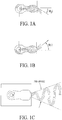
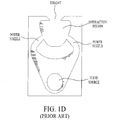
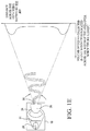
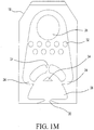
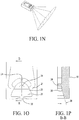
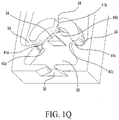
- FIGs. 1A-1Q illustrate nozzle assembly components and fluidic circuit configurations described in applicant's previous Three Jet Island fluidic circuit US patent 7651036 , and are included here partly to provide a consistent nomenclature.
- Figs 2-6B the structure and method of the present invention improve on that prior art by providing enhanced initiation of oscillation-inducing fluid dynamic (i.e., vortex formation and movement) mechanisms and enhanced reliably (meaning that the fluid jet steering mechanisms within the interaction chamber are maintained over a wider range of environmental conditions, especially when spraying cold or viscous fluids).
- the improved fluidic circuit geometries and methods illustrated in Figs 2-6B and described below are adapted for use in applicant's housing structures (such as housing 10, illustrated in Fig.
- a fluidic circuit e.g., 100, 200 or 300
- a nozzle assembly such as housing 10, illustrated in Fig. 1F ).
- Fluidic oscillators or fluidic circuits are often configured for use in housings which define a cavity, port or slot 20 and the new fluidic inserts (e.g., 100, 200 or 300) described below are configured in a nozzle assembly with a housing which defines a substantially hollow fluid-impermeable structure with an interior lumen and one or more cavities (e.g., 20) ports or slots defining a substantially rectangular passage or aperture with smooth interior slot wall surfaces.
- a nozzle assembly is configured to include one or more fluidic circuit inserts or chips (e.g., 100, 200 or 300) which are dimensioned to be tightly received in and held by the cavity or slot defined within the sidewall of the housing.
- the fluidic circuit insert e.g., 100, 200 or 300
- the nozzle assembly provides a channel for fluid communication between the housing's interior lumen (which provides a fluid inlet for pressurized fluid) and the exterior of the housing so that fluid entering the housing's interior lumen may be used to generate an oscillating spray directed distally and aimed by the orientation and configuration of the housing.
- the nozzle assembly's head (e.g., similar to 10, as illustrated in Fig. 1F ) may be in a two-piece configuration.
- the housing's nozzle head can include a cavity or socket (e.g., 20) which constitutes one of the two main nozzle pieces.
- the fluidic insert or chip (e.g., 100, 200, or 300) constitutes the other. If the nozzle head includes a cavity to receive a fluidic insert or chip, then a generally flat, planar floor surface defined in that cavity terminates in a wide, generally rectangular opening defined in the distal spray projecting side surface of the housing's distally projecting enclosure.
- a fluid transporting lumen from an inlet is in fluid communication with the interior of nozzle head and with a fluidic inlet supply channel or lumen which terminates in an opening in a cavity sidewall surface (e.g., sealing surface 22).
- the fluid supply lumens communicate with the interior volume defined within the nozzle head's cavity, and when pressurized fluid is pumped into and through the nozzle supply channel, that fluid flows into the cavity and into and through the fluidic (e.g., 100, 200, or 300).
- the fluidic insert or chip (e.g., 100, 200, or 300, as will be described in greater detail, below) is a generally flat member adapted to be forced or pressed into the housing's cavity 20 and securely retained therein by the pressure exerted by the housing cavity walls on the insert.
- the material from which the housing is fabricated is a solid plastic which deforms slightly under pressure.
- the cavity has a top wall and bottom wall which are spaced by a distance substantially equal to the thickness of the insert (e.g., 100, 200, or 300) between the insert top surface and bottom surface.
- the bottom surface may somewhat bowed, making the insert somewhat thicker along its middle.
- the insert's sidewalls are likewise spaced by a distance substantially equal to the width of insert between its left and right side or lateral edges.
- the fluidic circuit insert e.g., 100, 200, or 300
- the fluidic circuit insert may be a few thousandths of an inch wider than the nozzle head's cavity 20.
- the insert (e.g., 100, 200, or 300) and cavity 20 may taper along their axial lengths, being wider at the exposed distal end and narrowing toward the inserted proximal end. The taper may be gradual or may be effected in one or more discrete sections (e.g., as shown in Fig. 2 ), which are slightly angled toward one another.
- the fluidic oscillator is defined in the insert (e.g., 100, 200, or 300) as a plurality of recessed portions in the top surface of a substrate which define fluid passages. All of the fluidic's features are defined as recesses or troughs of equal or varying depths into the top surface of the insert or chip.
- the housing's internal lumen defines an opening into the cavity, and that opening aligns with and communicates with the insert's inlet, so that washer fluid or water flowing into the housing inlet (e.g., 16) flows into the fluidic's interaction chamber (e.g., 118, 218, or 318) to generate oscillating vortices therein, so that an oscillation is established and a jet of fluid is swept back and forth to generate the desired spray 130 which issues through the exit orifice (e.g., 120, 220, or 320).
- the exit orifice e.g., 120, 220, or 320
- the cavity's sidewalls 22 are spread slightly and in turn exert a higher pressure along the middle of the insert.
- the oscillator formed in top surface of the insert e.g., 100, 200, or 300
- nozzle head's cavity and fluidic insert may be arcuate, angled, or otherwise configured, depending upon the shape of nozzle head and spray pattern (e.g., 130) desired.
- oscillator channels may be defined in both the top and bottom surfaces of the insert or in the top and bottom walls of the cavity. The only limitation is that the fluidic oscillator, whichever surface or surfaces it is defined in, is sealed by the abutting surface(s) through the pressure exerted by the force fit within the housing's cavity.
- an improved method and apparatus for generating sprays includes a nozzle assembly preferably having a cavity (e.g., such as spray housing 10 with cavity 20, as shown in Fig. 1F ), but configured to receive an improved three jet island fluidic circuit 100.
- Fig. 2 is a top view or plan view diagram illustrating improved three jet island fluidic oscillator 100 having an interaction region 118 configured to receive and act upon first, second and third jets J1, J2, J3 entering from first power nozzle 114A, second power nozzle 114B and third power nozzle power nozzle 114C. As best seen in Figs.
- the center jet J2 flows distally along central axis 102 and impacts directly on a novel island-shaped obturator 126 which projects inwardly into interaction chamber 118, for use in generating precise and more uniform oscillating sprays with higher viscosity fluids, as illustrated in Fig. 3A .
- the first embodiment of the fluidic circuit of the present invention 100 as illustrated in Fig 2 has a plurality of sections which cooperate with one another to act upon the flowing fluid passing therethrough to generate a desired oscillating spray 130.
- the fluid flows from a proximal inlet (generally at 112) downstream or distally through the sections described below and is emitted as an oscillating spray of fluid droplets from the throat or outlet 120, and, for purposes of nomenclature, a central or flow axis 102 is defined as a straight line extending from the center of the feed inlet 110 to the center of the throat opening 120.
- the features acting on the distally flowing pressurized fluid flowing within and through oscillator circuit 100 are preferably symmetrically defined about central axis 102.
- improved three jet island oscillator circuit 100 is composed of first, second and third lumens or power nozzles 114A, 114B and 114C, which accelerate distally flowing fluid from inlet region 112 into interaction chamber 118 and a reconfigured island protuberance 126 that projects into interaction chamber 118 downstream of the center of the three power nozzles 14A, 14B, 14C.
- the interaction chamber 118 can be considered to have an upstream portion and a downstream portion, with the upstream portion having a pair of boundary edges and longitudinal centerline or central axis 102 equally spaced from these edges.
- the first and second power nozzles 114A and 114B are seen to be laterally spaced from the centerline and located at each of the edges of the interaction chamber's upstream portion, and the third power nozzle 114C is located on approximately the centerline of the interaction chamber's upstream portion.
- interaction chamber 118 has a selected width I W and terminates distally or downstream at a centered outlet lumen or throat 120 from which an oscillating spray exhausts and is defined between right side and left side sidewalls that diverge downstream.
- Throat 120 is nominally symmetrically defined around the centerline 102 and preferably defines a rectangular lumen having a selected transverse Throat Width T W .
- island 126 is spaced distally directly downstream of third power nozzle 114C on centerline 102 and has a substantially planar transverse distal island wall segment having selected transverse island width I W .
- Each Power Nozzle generates a flow along a selected power nozzle flow axis having a selected flow axis angle and has a selected Power nozzle Width P W which generates a corresponding aimed fluid jet J1, J2, J3 centered initially along the selected power nozzle's flow axis.
- the first and second laterally spaced power nozzles 114A, 114B generate first and second fluid jets J1, J2 which intersect in the interaction region downstream or distally of the island 126 at a Jet intersection point J L and at a selected obtuse jet intersection angle, J A .
- the jet intersection angle "J A " is particularly defined as "obtuse” because it is greater than a right angle (or 90 degrees) but less than 180 degrees.
- J A is in the range of 100 degrees to 140 degrees.
- J A is 110 degrees.
- Island 126 is seen to be configured distally or downstream of the outer or first and second laterally spaced power nozzles 114A, 114B, as shown in Figs 2 and 4A-4C .
- the first, second and third orifices 114A, 114B and 114C are defined between the interaction chamber's opposing left and right side walls and first and second curved, transverse fluid impermeable wall segments 140, 150, where the first curved, transverse wall segment 140 provides a first concave wall surface 142 defining a first cylindrical wall section of a selected radius and the second curved transverse wall segment 150 provides a second concave wall surface 152 defining a second cylindrical wall section of a second selected radius which is substantially equal to said first concave wall surface's selected radius.
- the first and second concave wall surfaces 142, 152 define laterally offset cylindrical wall sections configured to receive and contain laterally offset fluid vortices (see, e.g., Figs 4A and 4C ) which are formed, grow and move about within the interaction chamber 118.
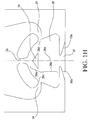
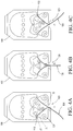
- the three fluid jets J1, J2, J3 cause vortices to form and move about within interaction chamber 118 in a bistable periodic oscillation cycle illustrated sequentially in Figs 4A, 4B and 4C .
- the bistable oscillation cycle is initiated when the center jet J3 alternates on each side of the interaction chamber's upwardly projecting island 126 and alternately sheds or generates laterally spaced (e.g., left and right side) vortices.
- center jet J3 is on one side of the island (i.e., the left side) resulting in a large vortex LV on that left side.
- Left side vortex LV partially blocks or suppresses the left side jet J1 flowing from the left side orifice 114A, resulting in (a) initiation of a right side vortex upstream of island 126 and proximate the right side orifice 114B and (b) the right jet J2 dominating the output jet exiting the outlet orifice or throat lumen 120, thereby defining the left extreme end or edge of the traverse defining the fan shape of the fluidic's spray 130.
- the left side vortex and right side vortex both move distally within chamber 118 and the center jet J3 is laterally displaced or forced to begin moving towards the opposing (i.e., right) side of island 126.
- the first, second and third jets J1, J2, J3 cause the vortices to form and move laterally and distally within the interaction chamber 118 in a bistable periodic oscillation cycle which is initiated when center jet J3 begins alternating on left and right (or laterally opposing) sides of the upwardly projecting island 126 which causes center jet J3 to alternately shed or generate the distally moving laterally spaced (e.g., left and right side) vortices.
- enhanced three jet island fluidic circuit 100 generates improved sprays with cold, viscous fluids and a more uniform spray pattern within a given nozzle assembly's spray fan angle.
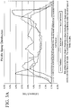
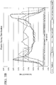
- the spray performance is illustrated as the plotted solid line in Fig.
- FIG. 3A which illustrates the cell volume percentage of total spray across the spray pattern's fan (for a selected spray fan angle see, e.g., Figs 1C and 1E ).
- the resulting spray volume per cell varied from about 1.6% of the total volume to about 2.2% of the total volume, which is much more uniform that the sprays generated by the applicant's prior art feedback oscillator (dotted line) or mushroom oscillator (dashed line).
- jet intersection angle J A is in the range of 100 degrees to 140 degrees. Applicants have tested in the range of 90 - 180 degrees and found that J A should be in the range of 100 degrees to 140 degrees (preferably 110 degrees) to perform the best for the above configuration.
- first, second and third orifices 114A, 114B and 114C are defined between the interaction chamber's opposing left and right side walls and the inverted bowl shaped first and second curved, transverse fluid impermeable wall segments 140, 150.
- First concave wall surface 142 defines a first cylindrical wall section and provide a first or left side vortex generating area which is upstream of or above and to the left of island 126.
- Second concave wall surface 152 defines a second cylindrical wall section and provides a mirror image or right side vortex generating area which is upstream of or above and to the right of island 126.
- the first and second concave wall surfaces 142, 152 define laterally offset cylindrical wall sections and the symmetrically configured left and right side vortex generation areas are configured to generate and contain laterally offset fluid vortices (see, e.g., Figs 4A and 4C ) which are formed, grow and move about within the interaction chamber118.
- Triangular island 126 is centered laterally on central axis 102, with the island's proximal or upward tip axially aligned with and pointing to the center of the center or third power nozzle 114C which is also centered on central axis 102.
- first, second and third orifices 114A, 114B and 114C shown to be defined between the interaction chamber's opposing left and right side walls and first and second curved, transverse fluid impermeable wall segments 140, 150, where the first curved, transverse wall segment 140 provides a first concave wall surface 142 defining a first cylindrical wall section of a selected radius and the second curved transverse wall segment 150 provides a second concave wall surface 152 defining a second cylindrical wall section of a second selected radius which is substantially equal to said first concave wall surface's selected radius.
- the first and second concave wall surfaces 142, 152 define laterally offset cylindrical wall sections configured to receive and contain laterally offset fluid vortices (see, e.g., Figs 4A and 4C ) which are formed, grow and move about within the interaction chamber118.
- each power nozzle defines a rectangular groove or trough having a selected depth ("P D ”) and power nozzle width ("Pw”).
- Fluidic 100 is configured to spray windshield washing fluid so the typical power nozzle depth (“P D ”) is 1.3 millimeters ("mm”) and the power nozzle width (“Pw”) is 0.55mm.
- the configuration of the fluid passages and the internal structural features defining fluidic circuit 100 are characterized in terms of linear dimensions or spacings and applicants have discovered relationships among those dimensions can be scaled up or down depending on the fluid spray application and expressed in terms of multiples of power nozzle width ("Pw").
- the features within interaction chamber 118 are configured at selected locations along central axis 102 between the center power nozzle 114C and outlet orifice 120, which is centered in the interaction chamber's distal end wall 160 which provides the reference line for measuring these axial distances.
- Improved three jet island fluidic circuit 100 when configured as illustrated in Figs 2 , 4A-4C with a throat width of 1 mm and a throat depth of 1.3mm (providing a rectangular spray orifice 120) is capable of generating spray velocity of approximately 14m/s when pressurized with a flow of 840 ml per minute at a temperature of -5,5 °C (22 degrees Fahrenheit), to generate a spray fan with a 60 degree fan angle.
- This is enabled because the geometry of the features within interaction chamber 118 provides a smaller than expected throat area to power nozzle area ratio for a spray's given fan angle (e.g., within the range of 20 degrees to 120 degrees).
- throat area is 60% of the power nozzle area.
- throat area is 100% of the power nozzle area for the same fan angle.
- pressure losses leading to the throat 120 are lower, which makes a higher spray velocity possible.
- the higher spray velocity demonstrated is a significant improvement for better dynamic performance (spray performance against wind speed as seen in automotive applications), compared with prior art nozzles.
- Island location, island width, Jet angle (J A ) of 110 degrees and the larger vortex formation area (available for vortices upstream of the island) allow the fluidic 100 to begin oscillating (or "start") at a lower fluid pressure with high viscosity liquids.
- a nozzle spray pattern with a full fan angle e.g., 60 degrees
- 20,6 kPa (3 psi) and above is achieved at 20,6 kPa (3 psi) and above.
- Applicants also found improved cold performance for smaller values of island width. It is a combination of these features that provide better cold performance than earlier embodiments.
- Figs 3A and 3B measured spray performance plots (Volume distribution of the spray fan (fan angle of 60 degrees)) are illustrated, in which the Y axis represents cell volume % of total and X axis is the cell number.
- the performance of the nozzle assembly using fluidic circuit 100 is illustrated in the solid line of Fig. 3A and shows a more uniform distribution, meaning that when in use, the nozzle assembly spreads sprayed liquid more evenly over its fan angle than prior art nozzles. This performance is clearly more uniform than for feedback fluidic or mushroom fluidic types of fluidic nozzles.
- Fig. 3B illustrates (in the dot-dash trace as shown on the right side of the legend) the plotted measured spray performance for another improved three jet island fluidic oscillator configured for a heavy-ended spray pattern embodiment as described above (with larger lumen area power nozzles 114A and 114B as described for option 2, having the smaller lumen center power nozzle (e.g., 114C)).
- an oscillation cycle for three jet bistable oscillator 100 is generated when the center jet ("J3") flows distally and alternately flows on opposing left and right sides of island 126 and alternately sheds vortices as shown.
- center jet is on the left side as is the large vortex LV.
- This vortex LV blocks or suppresses the left side jet J1, resulting in the right jet J2 dominating the output jet exiting the throat lumen 120 which is then swept to the left extreme of the fan angle for spray 130.
- the center jet begins to move towards the right side of the island. During this phase the output jet is passing through the center of the fan issuing from throat lumen 120.
- the center jet is on the right side of the island and the output jet is at its right extreme of the fan. This cycle repeats itself at relatively high frequency (as high as 300 Hz depending on size and operating pressures/flow rates).
- the method for controlling fluids in the three jet bistable oscillator 100 of the present invention requires a fluidic oscillator (e.g., 100, 200 or 300 (described below) operating on a pressurized fluid flowing therethrough to generate an exhaust flow in the form of an oscillating spray of fluid droplets (e.g., 130, 330), where the oscillator includes: an inlet (e.g., filling region 112 which may optionally include an array of filter posts 122) for the pressurized fluid, which then flows into first, second and third power nozzles 114A, 114B, 114C, each having a floor and sidewalls that are configured to define a venturi-shaped tapered lumen to accelerate the movement of that pressurized fluid to form first, second and third jets of fluid that flow from each said power nozzle, where each power nozzle's resulting jet is aligned along a selected jet-flow axis.
- a fluidic oscillator e.g., 100, 200 or 300 (described below) operating
- the fluidic oscillator defines a fluid communication pathway that connects and allows for the flow of the fluid between the inlet 112 and the first, second and third power nozzles, and that fluid communication pathway has a boundary surface that includes a pair of sidewalls to define an interaction chamber 118 which is in fluid communication with the first, second and third power nozzles and which receives first, second and third jet flows from the first, second and third power nozzles.
- Interaction chamber 118 has a floor, an outlet orifice 120 from which the oscillating spray exhausts, and an upwardly or inwardly projecting island protuberance 126 defining first, second and third island wall segments projecting upwardly from the floor of chamber 118 and placed at an intersection of the jet-flow axes such that island 126 is impacted by the first, second and third jets from the first, second and third power nozzles (as seen in Figs 4A, 4B and 4C ).
- Island 126 is spaced from but is preferably aligned along a common longitudinal axis of symmetry with outlet orifice 120 within interaction chamber 118.
- Tee-island three jet oscillator circuit 200 is composed of first, second and third power nozzles 214A, 214B, 214C, which accelerate fluid from inlet region 212 into interaction chamber 218 and Tee-island protuberance 226 projects into interaction chamber 218 downstream of the center of the three power nozzles 214C.
- the interaction chamber 218 can be considered to have an upstream portion and a downstream portion, with the upstream portion having a pair of boundary edges and a longitudinal centerline or central axis equally spaced from these edges.
- the first and second power nozzles 214A and 214B are seen to be laterally spaced from the centerline and located at each of the edges of the interaction chamber's upstream portion, and the third power nozzle 214C is located on approximately the centerline or central axis of symmetry of the interaction chamber's upstream portion.
- Interaction chamber 218 has a selected width I W and terminates distally or downstream at a centered outlet lumen or throat orifice 220 from which an oscillating spray exhausts and is defined between right side and left side sidewalls that diverge downstream.
- Throat orifice 220 is nominally symmetrically defined around the centerline and defines a rectangular lumen having a selected transverse Throat Width T W .
- Tee-Island 226 is located directly downstream of central power nozzle 214C that is located on the centerline of the interaction chamber 218 and has a selected transverse Island Width I W .
- Each Power Nozzle generates a flow along a selected power nozzle flow axis having a selected flow axis angle and has a selected Power nozzle Width P W which generates a jet centered initially along the selected power nozzle flow axis.
- the first and second laterally spaced power nozzles 214A, 214B generate first and second fluid jets which intersect in the interaction region downstream or distally of the island 226 at a Jet intersection point J L and at a selected Jet intersection Angle, J A .
- first, second and third orifices 214A, 214B and 214C shown to be defined between the interaction chamber's opposing left and right side walls and first and second curved, transverse fluid impermeable wall segments 240, 250, where the first curved, transverse wall segment 240 provides a first concave wall surface 242 defining a first cylindrical wall section of a selected radius and the second curved transverse wall segment 250 provides a second concave wall surface 252 defining a second cylindrical wall section of a second selected radius which is substantially equal to said first concave wall surface's selected radius.
- the first and second concave wall surfaces 242, 252 define laterally offset cylindrical wall sections configured to receive and contain laterally offset fluid vortices which are formed, grow and move about within the interaction chamber 218.
- another Tee-island three jet oscillator circuit 300 is composed of first, second and third power nozzles 314A, 314B, 314C, which accelerate fluid from inlet region 312 into interaction chamber 318 and Tee-island protuberance 326 projects into interaction chamber 318 downstream of the center of the three power nozzles 314C.
- the interaction chamber 318 can be considered to have an upstream portion and a downstream portion, with the upstream portion having a pair of boundary edges and a longitudinal centerline or central axis equally spaced from these edges.
- the first and second power nozzles 314A and 314B are seen to be laterally spaced from the centerline and located at each of the edges of the interaction chamber's upstream portion, and the third power nozzle 314C is located on approximately the centerline or central axis of symmetry of the interaction chamber's upstream portion.
- Interaction chamber 318 has a selected width IW and terminates distally or downstream at a centered outlet lumen or throat orifice 320 from which an oscillating spray exhausts and is defined between right side and left side sidewalls that diverge downstream.
- Throat orifice 320 is nominally symmetrically defined around the centerline and defines a rectangular lumen having a selected transverse Throat Width TW.
- Tee-Island 326 is located directly downstream of central power nozzle 314C that is located on the centerline of the interaction chamber 318 and has a selected transverse Island Width IW.
- Each Power Nozzle generates a flow along a selected power nozzle flow axis having a selected flow axis angle and has a selected Power nozzle Width PW which generates a jet centered initially along the selected power nozzle flow axis.
- the first and second laterally spaced power nozzles 314A, 314B generate first and second fluid jets which intersect in the interaction region downstream or distally of the island 326 at a Jet intersection point J L and at a selected Jet intersection Angle, J A .
- the fluidic oscillator geometries illustrated in Figs 5A and 5B are similar in operation, but island 326 illustrated in Fig. 5B is larger and has been made more "plastic injection mold friendly" than island 226 as illustrated in Fig. 5A .
- first, second and third orifices 314A, 314B and 314C shown to be defined between the interaction chamber's opposing left and right side walls and first and second curved, transverse fluid impermeable wall segments 340, 350, (e.g., as shown in Fig. 6B ) where the first curved, transverse wall segment 340 provides a first concave wall surface 342 defining a first cylindrical wall section of a selected radius and the second curved transverse wall segment 350 provides a second concave wall surface 352 defining a second cylindrical wall section of a second selected radius which is substantially equal to said first concave wall surface's selected radius.
- the first and second concave wall surfaces 342, 352 define laterally offset cylindrical wall sections configured to receive and contain laterally offset fluid vortices which are formed, grow and move about within the interaction chamber 318.
- Figs 6B and 6C by appropriately pressuring, orienting and scaling these elements, one is able to generate improved flow vortices upstream or proximally of (before) and downstream or distally of (behind) island 326 and those moving vortices are swept out of the throat 320 in a more uniform manner such that the vortices are alternately proximate the throat's right sidewall and then its left sidewall.
- a tee-island shape and position have been selected as a preferred embodiment for island 326.
- Substantially Tee-shaped island 326 has a laterally projecting transverse wall segment terminating in left and right side wall ends or points as well as a proximally projecting axially aligned wall segment terminating proximally in a wall end or point which faces the distally flowing oncoming fluid from the center power nozzle 314C, as best seen in Figs 6B and 6C .
- the purpose of the fluidic circuits of Figs 5A and 5B is to improve to further "starting" and cold performance. Typically the goal is to reduce nozzle pressure below 117,5 kPa (17 psi) for a 50-50 mix of ethanol at zero degrees F (where liquid viscosity >20 mPa ⁇ s (>20 cP)).
- sprays 230 and 330 and spray edges from the outlet orifice are much crisper (i.e. testing showed more liquid volume at spray edges, resulting in a cleaner fan appearance).
- spray oscillation is more efficient, so for a given TA (throat area)/PA (power nozzle area) ratio, the spray fan angle for sprays 230 and 330 is higher.
- the main feature for fluidic embodiments 200 and 300 of Figs 5A and 5B is the modified Tee island shape that resulted in better startup for cold temperatures and higher viscosity fluids (which is characterized and better "cold performance"). This improvement was obtained by designing for better oscillation initiation or starting.
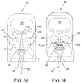
- Fig 6A which shows the improved three jet island oscillator 100, as illustrated in Fig. 2 and described above
- Figs 6B and 6C which shows proposed Tee island shapes for the present invention
- the triangular island 126 of oscillator 100 (isosceles triangle) performs fine with water thinned to medium viscosity (e.g. .
- Fig. 6A illustrates a symmetrical (monostable, non-oscillating) flow field within interaction chamber 318 onto triangular island 126 of oscillator 100 (as described above) and Fig. 6B illustrates a momentarily symmetrical flow field for the newer Tee island oscillator 300.
- Fig. 6C illustrates an oscillating flow field for the newer Tee island oscillator 300.
- the newer embodiments of the present invention solve this problem by providing (e.g., in Tee-Islands 226, 326) first and second L-shaped island wall segments or inside corner shaped pockets configured to receive flow from center jet ("J3") and, in response, create first and second very small counter-rotating island-pocket vortices IV CCW and IV CW (see, e.g., Fig. 6B ), in the opposing left and right side inside corner wall segments defined by inverted Tee island 326.
- First and second counter rotating micro-vortices are set up when the center jet ("J3") splits around the island. These counter rotating micro-vortices IV CCW and IV CW become stronger and larger as pressure (and flow) is increased.
- the pressurized fluid flow pressure required to force initiation of oscillation in Tee-Island fluidic oscillator 300 is called the "switching pressure" and, as mentioned earlier, the switching pressure for oscillator 300 is less than 117,2 kPa (17 psi), which is a significant improvement over the switching pressure required for the prior art and even over earlier prototypes (e.g., 100 as shown in Figs 2 and 6A ) where switching pressures exceed 172,3 kPa (25 psi).
- Tee-Island Fluidic Oscillators 200 and 300 are similar to those described above for the Improved Three Jet Island Fluidic Oscillator 100. Particularly,
- the Interaction region width, Iw Applicants found optimum values in the range of 12.5 - 13.5 times the Power Nozzle Width, Pw (preferably 13Pw); Interaction region height, I I : This is a critical dimension and varies between 7.5 - 8.5Pw; Jet intersection point, J I : This is a critical dimension and varies from 2.5 - 3Pw; Jet intersection angle, J A : As mentioned above optimum performance is achieved when the jet-flow axes for the outer-most jets J A is in the range of 100 degrees to 140 degrees, and is preferably around 110 degrees (as seen in Figs 6B and 6C ); and
- Circuit 300 is capable of spray velocity of approximately 14m/s. This is enabled because of the specialized geometry leading to a smaller throat area to power nozzle area ratio for a given fan angle.
- an improved nozzle assembly and an improved fluidic oscillator circuit (e.g., 100, 200, 300) available which operates on a pressurized fluid to generate an oscillating spray of fluid droplets, and the oscillator aims fluid jets from first, second and third power nozzles (e.g., 114A, 114B, 114C) into an interaction chamber (e.g., 118) and toward an upwardly projecting island protuberance (e.g., 126) defining first, second and third island wall segments.
- Each power nozzle has a selected rectangular lumen area and width ("P W ").
- the island is spaced from and aligned along a common axis (e.g., 102) with an outlet orifice (e.g., 120) at the distal end of interaction chamber which defines an interaction region having an axial length, I I in the range of 7.5 - 8.5Pw.
- the outermost jets e.g., 114A, 114B
- J I Jet intersection point
- the upstream end of interaction chamber is defined by first and second laterally offset concave wall bowl-shaped surfaces (e.g., 142, 152) which define left side and right side vortex generating areas so that fluid jet steering vortices may be alternately formed and then displaced distally to steer the fluid jet laterally within interaction chamber as fluid is pumped through and thereby reliably create and maintain a laterally oscillating spray fan which projects from the outlet orifice into a spray (e.g., 130, 230, 330) having a selected fan angle in the range of 20-120 degrees with the improved spray velocity described above.
- a spray e.g., 130, 230, 330
Landscapes
- Nozzles (AREA)
- Special Spraying Apparatus (AREA)
Claims (17)
- Oscillateur fluidique (100, 200, 300) agissant sur un fluide sous pression, qui s'écoule à travers celui-ci, pour générer un écoulement d'échappement sous la forme d'une pulvérisation oscillante de gouttelettes de fluide, ledit oscillateur comprenant :une entrée pour ledit fluide sous pression,des premier, deuxième et troisième injecteurs principaux, dont chacun dispose d'un plancher et de parois latérales qui sont configurés pour accélérer le mouvement dudit fluide sous pression qui s'écoule à travers lesdits premier, deuxième et troisième injecteurs principaux pour former un jet de fluide qui s'écoule à partir de chacun desdits injecteurs principaux,une voie de communication de fluide qui relie et permet l'écoulement dudit fluide entre ladite entrée et lesdits premier, deuxième et troisième injecteurs principaux, ladite voie de communication de fluide a une surface limite qui comporte une paire de parois latérales, et une chambre d'interaction (118, 218, 318) en communication fluidique avec lesdits premier, deuxième et troisième injecteurs principaux qui reçoit des premier, deuxième et troisième écoulements de jet à partir desdits premier, deuxième et troisième injecteurs principaux ;ladite chambre d'interaction (118, 218, 318) dispose d'un plancher, d'un orifice de sortie (120, 220, 320) à partir duquel ladite pulvérisation s'échappe de ladite chambre d'interaction, et d'une protubérance d'îlot (126, 226, 326) faisant saillie vers le haut, définissant des premier, deuxième et troisième segments de paroi d'îlot faisant saillie vers le haut à partir dudit plancher de chambre dans une position qui est frappée par lesdits premier, deuxième et troisième jets provenant des premier, deuxième et troisième injecteurs principaux,dans lequel ladite protubérance d'îlot faisant saillie vers le haut est espacée dudit orifice de sortie, mais alignée le long d'un axe commun (102, 202, 302) avec celui-ci, à l'intérieur de ladite chambre d'interaction ; etdans lequel lesdits premier et deuxième jets (J1, J2) sont alignés le long de premier et deuxième axes de jets qui se coupent à un angle JA d'intersection de jet qui est dans la plage allant de 100 à 140 degrés,dans lequel ladite chambre d'interaction définit une région d'interaction configurée pour initier des tourbillons internes dans des zones de génération de tourbillons espacées latéralement, qui se trouvent en amont de la protubérance d'îlot (126, 226, 326), dans lequel lesdits tourbillons sont forcés distalement ou en aval et se répandent sur des côtés alternés de la protubérance d'îlot (126, 226, 326),dans lequel lesdits premier, deuxième et troisième injecteurs principaux de la chambre d'interaction sont définis entre les parois latérales gauche et droite opposées de la chambre d'interaction, et des premier et deuxième segments de paroi en forme de bol inversé ;dans lequel ledit premier segment de paroi en forme de bol fournit une zone de génération de tourbillons d'un premier côté ou côté gauche, qui se trouve en amont ou au-dessus et à gauche dudit îlot, et ledit deuxième segment de paroi en forme de bol fournit une zone de génération de tourbillons du côté en image inverse ou côté droit, qui se trouve en amont ou au-dessus et à droite dudit îlot ; etdans lequel des zones de génération de tourbillons symétriques à gauche et à droite sont configurées pour générer et contenir des tourbillons de fluide décalés latéralement en amont de la protubérance d'îlot (126, 226, 326).
- Oscillateur fluidique (100, 200, 300) selon la revendication 1, dans lequel lesdits premier, deuxième et troisième injecteurs principaux ont chacun des parois latérales espacées par une largeur Pw d'injecteur principal, et dans lequel ladite chambre d'interaction définit une région d'interaction ayant une largeur de région d'interaction, Iw, qui est dans la plage allant de 12,5 à 13,5 fois la largeur Pw d'injecteur principal.
- Oscillateur fluidique (100, 200, 300) selon la revendication 2, où ladite région d'interaction a une longueur ou une hauteur axiale, lI : dans la plage allant de 7,5 à 8,5 Pw.
- Oscillateur fluidique (100, 200, 300) selon la revendication 3, dans lequel lesdits premier et troisième jets se coupent en un point d'intersection de jets, JI, qui est espacé dudit orifice d'une distance de à 2,5 à 3 Pw.
- Oscillateur fluidique (100, 200, 300) selon la revendication 4, dans lequel lesdits premier et deuxième jets (J1, J2) sont alignés le long de premier et deuxième axes de jets qui se coupent à un angle JA d'intersection de jet qui est d'environ 110 degrés.
- Oscillateur fluidique (100, 200, 300) selon la revendication 1, dans lequel lesdits premier et deuxième jets (J1, J2) sont alignés le long de premier et deuxième axes de jets qui se coupent à un angle JA d'intersection de jet qui est d'environ 110 degrés.
- Oscillateur fluidique (100, 200, 300) selon la revendication 1, dans lequel lesdits premier et deuxième injecteurs principaux ont une superficie de lumière plus grande que ledit troisième injecteur principal, et dans lequel ledit oscillateur fluidique génère une pulvérisation en éventail à extrémité lourde.
- Oscillateur fluidique (100) selon la revendication 1, dans lequel ladite protubérance d'îlot faisant saillie vers le haut de la chambre d'interaction définit des premier, deuxième et troisième segments de paroi d'îlot, sensiblement linéaires, faisant saillie vers le haut à partir dudit plancher de chambre, dans une protubérance symétrique de génération de tourbillon (126), à section triangulaire, qui est frappée par un jet de fluide provenant dudit troisième injecteur principal (central) dans un écoulement qui est initialement sensiblement parallèle audit axe commun (102).
- Oscillateur fluidique (200, 300) selon la revendication 1, dans lequel ladite protubérance d'îlot faisant saillie vers le haut (226, 326) de la chambre d'interaction définit des premier et deuxième segments de paroi d'îlot en forme de L faisant saillie vers le haut à partir dudit plancher de chambre qui définissent, avec un troisième segment de paroi, une protubérance symétrique de génération de micro-tourbillon contrarotatif (226, 326), à section en T, fournissant des segments intérieurs de paroi en forme de coin d'accrochage de jet aigu, des côtés gauche et droit, qui sont frappés par ledit deuxième jet provenant dudit deuxième injecteur principal, dans un écoulement qui est initialement sensiblement parallèle audit axe commun avec ledit orifice de sortie (320) à l'intérieur de ladite chambre d'interaction,
dans lequel ledit segment intérieur de paroi en forme de coin d'accrochage de jet aigu du côté gauche est configuré pour recevoir un écoulement de fluide incident et générer un premier micro-tourbillon ayant une première direction de rotation, et dans lequel ledit segment intérieur de paroi en forme de coin d'accrochage de jet aigu du côté droit va générer un deuxième micro-tourbillon, ayant une deuxième direction de rotation opposée à la direction dudit premier micro-tourbillon, en réponse audit écoulement incident. - Oscillateur fluidique (200, 300) selon la revendication 9, dans lequel lesdits premier et deuxième jets (J1, J2) (les plus à l'extérieur) sont alignés le long de premier et deuxième axes de jets qui se coupent à un angle JA d'intersection de jet qui est d'environ 110 degrés.
- Oscillateur fluidique (200, 300) selon la revendication 9, dans lequel lesdits premier et deuxième injecteurs principaux (les plus à l'extérieur) ont une superficie de lumière plus grande que ledit troisième injecteur principal, et dans lequel ledit oscillateur fluidique génère une pulvérisation en éventail à extrémité lourde.
- Oscillateur fluidique (200, 300) selon la revendication 9, dans lequel lesdits éléments fluidiques à îlot en T (200, 300) initient et maintiennent un motif de pulvérisation oscillante et fonctionnent à des pressions de fluide considérablement inférieures à la normale, par exemple, moins de 117,2 kPa (17 psi) pour un mélange eau-éthanol à 50-50, et dans lequel ladite pulvérisation a une vitesse de pulvérisation d'environ 14 m/s.
- Ensemble d'injecteur configuré pour diriger une pulvérisation d'oscillateur fluidique sur une surface à pulvériser, comprenant :un boîtier avec une cavité configurée pour recevoir et supporter un oscillateur fluidique (100, 200 ou 300) ;l'ensemble d'injecteur, comprenant l'oscillateur fluidique (100, 200, 300) agissant sur un fluide sous pression qui s'écoule à travers celui-ci, pour générer un écoulement d'échappement sous la forme d'une pulvérisation oscillante de gouttelettes de fluide, ledit oscillateur comporte des passages de fluide dans un substrat définissant une entrée pour ledit fluide sous pression, et des premier, deuxième et troisième injecteurs principaux, dont chacun dispose d'un plancher et de parois latérales qui sont configurés pour accélérer le mouvement dudit fluide sous pression qui s'écoule à travers lesdits premier, deuxième et troisième injecteurs principaux, pour former un jet de fluide qui s'écoule à partir de chacun desdits injecteurs principaux,ledit oscillateur dirige des jets de fluide provenant des premier, deuxième et troisième injecteurs principaux (114A, 114B, 114C) dans une chambre d'interaction (118) et vers une protubérance d'îlot faisant saillie vers le haut (126) définissant des premier, deuxième et troisième segments de paroi d'îlot, dans lequel chaque injecteur principal a une superficie de lumière rectangulaire sélectionnée et une largeur ("PW") ;dans lequel l'îlot (126) est espacé d'un orifice de sortie (120), et aligné le long d'un axe commun (102) avec celui-ci, à l'extrémité distale de la chambre d'interaction (118), et la chambre d'interaction définit une région d'interaction ayant une longueur axiale, lI, dans la plage allant de 7,5 à 8,5 Pw ;ledit élément fluidique comporte en outre une voie de communication de fluide qui relie et permet l'écoulement dudit fluide entre ladite entrée et lesdits premier, deuxième et troisième injecteurs principaux, ladite voie de communication de fluide a une surface limite qui comporte une paire de parois latérales, et une chambre d'interaction (118, 218, 318) en communication fluidique avec lesdits premier, deuxième et troisième injecteurs principaux, qui reçoit des premier, deuxième et troisième écoulements de jet à partir desdits premier, deuxième et troisième injecteurs principaux ;ladite chambre d'interaction (118, 218, 318) dispose d'un plancher, d'un orifice de sortie (120, 220, 320) à partir duquel ladite pulvérisation s'échappe de ladite chambre d'interaction, et d'une protubérance d'îlot (126, 226, 326) faisant saillie vers le haut, définissant des premier, deuxième et troisième segments de paroi d'îlot faisant saillie vers le haut à partir dudit plancher de chambre,dans lequel ladite protubérance d'îlot faisant saillie vers le haut est espacée dudit orifice de sortie, mais alignée le long d'un axe commun (102, 202, 302) avec celui-ci, à l'intérieur de ladite chambre d'interaction ; etdans lequel lesdits premier et deuxième jets (J1, J2) sont alignés le long de premier et deuxième axes de jets qui se coupent à un angle JA d'intersection de jet qui est de 100 à 140 degrés, etdans lequel des jets (114A, 114B) les plus à l'extérieur sont dirigés à un angle obtus de 100 à 140 degrés le long d'axes qui se coupent au-delà de l'îlot à un point JI d'intersection de jets, qui est espacé de l'orifice (120) d'une distance de 2,5 à 3 Pw, et dans lequel l'extrémité amont de la chambre d'interaction (118) est définie par des première et deuxième surfaces de paroi concaves (142, 152) décalées latéralement, qui définissent des zones de génération de tourbillons du côté gauche et du côté droit, de sorte que des tourbillons de direction de jet de fluide puissent être formés en alternance et déplacés ensuite distalement pour diriger le jet de fluide latéralement à l'intérieur d'une chambre d'interaction (118) et créer et maintenir efficacement un éventail de pulvérisation oscillante latéralement, qui se projette à partir d'un orifice (120) dans un angle d'éventail sélectionné de 20 à 120 degrés.
- Ensemble d'injecteur selon la revendication 13, dans lequel lesdits premier, deuxième et troisième injecteurs principaux ont chacun des parois latérales espacées d'une largeur Pw d'injecteur principal, et dans lequel ladite chambre d'interaction définit une région d'interaction ayant une largeur Iw de région d'interaction, qui est dans la plage allant de 12,5 à 13,5 fois la largeur d'injecteur principal.
- Ensemble d'injecteur selon la revendication 14, dans lequel ladite chambre d'interaction définit une région d'interaction configurée pour initier des tourbillons internes dans des zones de génération de tourbillons espacées latéralement, qui se trouvent en amont de la protubérance d'îlot (126, 226, 326) dans lequel lesdits tourbillons sont forcés distalement ou en aval, et qui se répandent sur des côtés alternés de la protubérance d'îlot (126, 226, 326).
- Procédé amélioré pour générer et maintenir une pulvérisation oscillante dans un oscillateur fluidique,
dans lequel une chambre d'interaction définit une région d'interaction configurée pour initier des tourbillons internes dans des zones de génération de tourbillons espacées latéralement, qui se trouvent en amont de la protubérance d'îlot (126, 226, 326), dans lequel lesdits tourbillons sont forcés distalement ou en aval et se répandent sur des côtés alternés de la protubérance d'îlot (126, 226, 326) ;
dans lequel lesdits premier, deuxième et troisième injecteurs principaux de la chambre d'interaction sont définis entre les parois latérales gauche et droite opposées de la chambre d'interaction et les premier et deuxième segments de paroi en forme de bol inversé ;
dans lequel ledit premier segment de paroi en forme de bol fournit une zone de génération de tourbillons d'un premier côté ou côté gauche, qui se trouve en amont ou au-dessus et à gauche dudit îlot, et ledit deuxième segment de paroi en forme de bol fournit une zone de génération de tourbillons du côté en image inverse ou côté droit, qui se trouve en amont ou au-dessus et à droite dudit îlot ; et
dans lequel des zones de génération de tourbillons symétriques à gauche et à droite sont configurées pour générer et contenir des tourbillons de fluide décalés latéralement en amont de la protubérance d'îlot (126, 226, 326),
ledit procédé comprenant les étapes de procédé consistant à :(a) fournir un oscillateur fluidique (100, 200 ou 300) ayant une entrée pour ledit fluide sous pression, des premier, deuxième et troisième injecteurs principaux, et un orifice de sortie défini le long d'un axe de pulvérisation central (102, 202, 302) ;(b) configurer des premier, deuxième et troisième injecteurs principaux dans ledit oscillateur fluidique pour accélérer le mouvement dudit fluide sous pression qui s'écoule à travers lesdits premier, deuxième et troisième injecteurs principaux, pour former des premier, deuxième et troisième jets de fluide s'écoulant dans une chambre d'interaction (118, 218, 318) où ces premier, deuxième et troisième jets vont s'écouler dans et contre une protubérance d'îlot qui est espacée mais alignée le long de l'axe central de pulvérisation (102, 202, 302) ; dans lequel lesdits premier et deuxième jets (J1, J2) (les plus à l'extérieur) sont alignés le long de premier et deuxième axes de jets qui se coupent à un angle JA d'intersection de jet qui est dans la plage allant de 100 à 140 degrés ;(c) faire passer un fluide dans ladite entrée à une pression sélectionnée, et initier des tourbillons internes dans des zones de génération de tourbillons espacées latéralement qui se trouvent en amont de la protubérance d'îlot (126, 226, 326) et, continuer à faire passer le fluide dans l'entrée.(d) forcer lesdits tourbillons distalement ou en aval à se répandre sur des côtés alternés de la protubérance d'îlot (126, 226, 326). - Procédé selon la revendication 16, dans lequel ledit écoulement de fluide est fourni à une pression sélectionnée inférieure à 17,2 kPa (17 psi) pour un mélange eau-éthanol à 50-50, et un motif de pulvérisation oscillante est initié et maintenu.
Applications Claiming Priority (3)
| Application Number | Priority Date | Filing Date | Title |
|---|---|---|---|
| US201462024762P | 2014-07-15 | 2014-07-15 | |
| US201562155826P | 2015-05-01 | 2015-05-01 | |
| PCT/US2015/040288 WO2016010971A1 (fr) | 2014-07-15 | 2015-07-14 | Circuit amélioré d'oscillateur fluidique à îlot à trois jets, procédé et ensemble d'injecteurs |
Publications (3)
| Publication Number | Publication Date |
|---|---|
| EP3169441A1 EP3169441A1 (fr) | 2017-05-24 |
| EP3169441A4 EP3169441A4 (fr) | 2018-03-07 |
| EP3169441B1 true EP3169441B1 (fr) | 2020-11-04 |
Family
ID=55078965
Family Applications (1)
| Application Number | Title | Priority Date | Filing Date |
|---|---|---|---|
| EP15822091.3A Active EP3169441B1 (fr) | 2014-07-15 | 2015-07-14 | Circuit amélioré d'oscillateur fluidique à îlot à trois jets, procédé et ensemble d'injecteurs |
Country Status (5)
| Country | Link |
|---|---|
| US (1) | US10532367B2 (fr) |
| EP (1) | EP3169441B1 (fr) |
| JP (1) | JP6545784B2 (fr) |
| CN (1) | CN106999960B (fr) |
| WO (1) | WO2016010971A1 (fr) |
Families Citing this family (25)
| Publication number | Priority date | Publication date | Assignee | Title |
|---|---|---|---|---|
| DE102015222771B3 (de) | 2015-11-18 | 2017-05-18 | Technische Universität Berlin | Fluidisches Bauteil |
| EP3309019A1 (fr) * | 2016-10-13 | 2018-04-18 | Fico Transpar, S.A. | Système de lavage |
| FR3069463B1 (fr) * | 2017-07-31 | 2020-07-17 | Saint-Gobain Isover | Installation de fabrication de laine minerale et dispositif de projection d’une composition d’encollage equipant une telle installation |
| JP7020001B2 (ja) * | 2017-08-31 | 2022-02-16 | 株式会社デンソー | 車載センサ洗浄装置 |
| CN111225838B (zh) | 2017-08-15 | 2023-06-13 | 株式会社电装 | 车载传感器清洗装置 |
| JP6399478B1 (ja) * | 2017-12-25 | 2018-10-03 | Toto株式会社 | 吐水装置 |
| FR3086513B1 (fr) * | 2018-10-02 | 2021-10-15 | Oreal | Procede de traitement cosmetique |
| FR3086514B1 (fr) * | 2018-10-02 | 2021-10-15 | Oreal | Procede de coloration capillaire |
| CN109488664B (zh) * | 2018-10-24 | 2020-12-18 | 上海交通大学 | 流体振荡装置 |
| GB201905126D0 (en) * | 2019-04-11 | 2019-05-29 | Perlemax Ltd | Fluidic oscilators |
| JP7441618B2 (ja) * | 2019-07-24 | 2024-03-01 | 株式会社Lixil | 吐出装置及び浴室設備 |
| DE112020004973T5 (de) * | 2019-10-18 | 2022-06-30 | Dhlbowles, Inc. | Fluidoszillator für eine Düsenanordnung für eine verbesserte Kaltleistung |
| US11712707B2 (en) * | 2019-11-07 | 2023-08-01 | Dlhbowles, Inc. | Uniform cold performance reverse mushroom |
| CN113446721B (zh) * | 2020-03-25 | 2023-04-07 | 约克广州空调冷冻设备有限公司 | 散流器 |
| US11643052B2 (en) * | 2020-09-29 | 2023-05-09 | Ford Global Technologies, Llc | Cleaning apparatus for sensor |
| CN112547330A (zh) * | 2020-11-30 | 2021-03-26 | 上海交通大学 | 一种无反馈管道的流体振荡器 |
| LU102636B1 (en) * | 2021-03-04 | 2022-09-05 | Stratec Se | Sensor for determining the oscillating frequency in a fluidic oscillating nozzle and a method using the sensor |
| US12702989B2 (en) * | 2021-07-26 | 2026-08-11 | Genesee Valley Innovations, LLC | Annular effervescent nozzle |
| CN114459073B (zh) * | 2022-02-28 | 2022-09-02 | 海信空调有限公司 | 空调器以及空调器的控制方法 |
| CN114964718B (zh) * | 2022-08-02 | 2022-10-11 | 北京科技大学 | 围压环境下射流空化及振荡特性检测装置、及其检测方法 |
| CN115899812A (zh) * | 2022-11-15 | 2023-04-04 | 海信空调有限公司 | 空调器 |
| US12698623B2 (en) | 2023-07-18 | 2026-08-04 | Kohler Co. | Multi-head fluidic oscillators |
| WO2026025025A1 (fr) * | 2024-07-26 | 2026-01-29 | Abc Technologies, Inc. | Modificateurs de région d'interaction améliorant les performances à basses températures pour circuits fluidiques |
| US20260027570A1 (en) * | 2024-07-26 | 2026-01-29 | Abc Technologies, Inc. | Five island fluidic circuit for low temperature performance of alcohol-based aqueous mixtures |
| CN120772033B (zh) * | 2025-09-11 | 2025-11-11 | 苏州嘉树医疗科技有限公司 | 一种喷头、喷雾器的泵体组件和喷雾器 |
Family Cites Families (26)
| Publication number | Priority date | Publication date | Assignee | Title |
|---|---|---|---|---|
| US3185166A (en) | 1960-04-08 | 1965-05-25 | Billy M Horton | Fluid oscillator |
| US3563462A (en) | 1968-11-21 | 1971-02-16 | Bowles Eng Corp | Oscillator and shower head for use therewith |
| DE2065063B2 (de) * | 1970-04-13 | 1973-08-02 | Bowles Fluidics Corp . Silver Spring, Md (V St A ) | Fluidik-oszillator |
| US4052002A (en) | 1974-09-30 | 1977-10-04 | Bowles Fluidics Corporation | Controlled fluid dispersal techniques |
| DE2505695A1 (de) | 1974-09-30 | 1976-04-22 | Bowles Fluidics Corp | Vorrichtung zum verspruehen eines fluids, insbesondere fluidischer oszillator |
| US4157161A (en) | 1975-09-30 | 1979-06-05 | Bowles Fluidics Corporation | Windshield washer |
| US4151955A (en) * | 1977-10-25 | 1979-05-01 | Bowles Fluidics Corporation | Oscillating spray device |
| US5035361A (en) | 1977-10-25 | 1991-07-30 | Bowles Fluidics Corporation | Fluid dispersal device and method |
| US4231519A (en) | 1979-03-09 | 1980-11-04 | Peter Bauer | Fluidic oscillator with resonant inertance and dynamic compliance circuit |
| US4508267A (en) | 1980-01-14 | 1985-04-02 | Bowles Fluidics Corporation | Liquid oscillator device |
| JPH06105083B2 (ja) * | 1986-04-24 | 1994-12-21 | 松下電工株式会社 | 流体発振素子 |
| DE3662770D1 (en) | 1986-10-01 | 1989-05-18 | Vogel Ignaz Fahrzeugsitze | Double passenger seat |
| US4905909A (en) | 1987-09-02 | 1990-03-06 | Spectra Technologies, Inc. | Fluidic oscillating nozzle |
| US5213269A (en) | 1991-09-13 | 1993-05-25 | Bowles Fluidics Corporation | Low cost, low pressure, feedback passage-free fluidic oscillator with interconnect |
| JP3628515B2 (ja) | 1997-05-29 | 2005-03-16 | 富士通株式会社 | 書き込み条件設定方法及びディスク装置 |
| US5971301A (en) | 1998-08-25 | 1999-10-26 | Bowles Fluidic Corporation | "Box" oscillator with slot interconnect |
| US6253782B1 (en) | 1998-10-16 | 2001-07-03 | Bowles Fluidics Corporation | Feedback-free fluidic oscillator and method |
| US6186409B1 (en) | 1998-12-10 | 2001-02-13 | Bowles Fluidics Corporation | Nozzles with integrated or built-in filters and method |
| US7651036B2 (en) * | 2003-10-28 | 2010-01-26 | Bowles Fluidics Corporation | Three jet island fluidic oscillator |
| BRPI0419186A (pt) * | 2004-11-01 | 2007-12-18 | Bowles Fluidics Corp | oscilador fluìdico de desempenho a frio aperfeiçoado |
| US7267290B2 (en) * | 2004-11-01 | 2007-09-11 | Bowles Fluidics Corporation | Cold-performance fluidic oscillator |
| US8702020B2 (en) * | 2008-05-16 | 2014-04-22 | Bowles Fluidics Corporation | Nozzle and fluidic circuit adapted for use with cold fluids, viscous fluids or fluids under light pressure |
| US9555422B2 (en) * | 2008-10-30 | 2017-01-31 | Dlhbowles, Inc. | Irrigation spray nozzles for rectangular patterns |
| US20110233301A1 (en) * | 2009-07-28 | 2011-09-29 | Bowles Fluidics Corporation (A Md Corporation) | Rain can style showerhead assembly incorporating eddy filter for flow conditioning in fluidic circuits |
| CN201470514U (zh) * | 2009-08-26 | 2010-05-19 | 深圳成霖洁具股份有限公司 | 流体喷射装置 |
| CN105121025B (zh) * | 2012-12-12 | 2018-09-11 | 鲍尔斯应用流体力学公司 | 射流喷嘴和振荡器回路 |
-
2015
- 2015-07-14 WO PCT/US2015/040288 patent/WO2016010971A1/fr not_active Ceased
- 2015-07-14 CN CN201580049495.XA patent/CN106999960B/zh active Active
- 2015-07-14 EP EP15822091.3A patent/EP3169441B1/fr active Active
- 2015-07-14 JP JP2017502206A patent/JP6545784B2/ja active Active
-
2017
- 2017-01-14 US US15/406,702 patent/US10532367B2/en active Active
Non-Patent Citations (1)
| Title |
|---|
| None * |
Also Published As
| Publication number | Publication date |
|---|---|
| US20170136472A1 (en) | 2017-05-18 |
| EP3169441A4 (fr) | 2018-03-07 |
| EP3169441A1 (fr) | 2017-05-24 |
| WO2016010971A1 (fr) | 2016-01-21 |
| CN106999960A (zh) | 2017-08-01 |
| JP2017529493A (ja) | 2017-10-05 |
| WO2016010971A9 (fr) | 2016-03-10 |
| US10532367B2 (en) | 2020-01-14 |
| JP6545784B2 (ja) | 2019-07-17 |
| CN106999960B (zh) | 2020-09-08 |
Similar Documents
| Publication | Publication Date | Title |
|---|---|---|
| US10532367B2 (en) | Three-jet fluidic oscillator circuit, method and nozzle assembly | |
| US10092913B2 (en) | Fluidic nozzle and improved moving vortex generating fluidic oscillator | |
| CN105121025B (zh) | 射流喷嘴和振荡器回路 | |
| US7775456B2 (en) | Fluidic device yielding three-dimensional spray patterns | |
| US7472848B2 (en) | Cold-performance fluidic oscillator | |
| US7651036B2 (en) | Three jet island fluidic oscillator | |
| EP1827703B1 (fr) | Oscillateur fluidique a performance de refroidissement amelioree | |
| KR101786120B1 (ko) | 다수의 스로트를 갖는 고효율의 유체 오실레이터 | |
| US20060065765A1 (en) | Fluidic nozzle for trigger spray applications | |
| CA3158460C (fr) | Dispositif d'oscillateur fluidique a sortie atomisee | |
| US20240116061A1 (en) | Fluidic oscillator for a nozzle assembly for enhanced cold performance | |
| WO2005042169A1 (fr) | Oscillateur fluidique comprenant trois injecteurs et un ilot |
Legal Events
| Date | Code | Title | Description |
|---|---|---|---|
| STAA | Information on the status of an ep patent application or granted ep patent |
Free format text: STATUS: THE INTERNATIONAL PUBLICATION HAS BEEN MADE |
|
| PUAI | Public reference made under article 153(3) epc to a published international application that has entered the european phase |
Free format text: ORIGINAL CODE: 0009012 |
|
| STAA | Information on the status of an ep patent application or granted ep patent |
Free format text: STATUS: REQUEST FOR EXAMINATION WAS MADE |
|
| 17P | Request for examination filed |
Effective date: 20170201 |
|
| AK | Designated contracting states |
Kind code of ref document: A1 Designated state(s): AL AT BE BG CH CY CZ DE DK EE ES FI FR GB GR HR HU IE IS IT LI LT LU LV MC MK MT NL NO PL PT RO RS SE SI SK SM TR |
|
| AX | Request for extension of the european patent |
Extension state: BA ME |
|
| RIN1 | Information on inventor provided before grant (corrected) |
Inventor name: GOPALAN, SHRIDHAR Inventor name: CAMERON, ANDREW Inventor name: ZHAO, CHUNLING |
|
| DAV | Request for validation of the european patent (deleted) | ||
| DAX | Request for extension of the european patent (deleted) | ||
| A4 | Supplementary search report drawn up and despatched |
Effective date: 20180207 |
|
| RIC1 | Information provided on ipc code assigned before grant |
Ipc: B05B 17/04 20060101ALI20180201BHEP Ipc: B60S 1/52 20060101ALI20180201BHEP Ipc: F15C 1/08 20060101ALI20180201BHEP Ipc: B05B 1/34 20060101ALI20180201BHEP Ipc: B05B 1/08 20060101AFI20180201BHEP |
|
| GRAP | Despatch of communication of intention to grant a patent |
Free format text: ORIGINAL CODE: EPIDOSNIGR1 |
|
| STAA | Information on the status of an ep patent application or granted ep patent |
Free format text: STATUS: GRANT OF PATENT IS INTENDED |
|
| INTG | Intention to grant announced |
Effective date: 20200529 |
|
| GRAS | Grant fee paid |
Free format text: ORIGINAL CODE: EPIDOSNIGR3 |
|
| GRAA | (expected) grant |
Free format text: ORIGINAL CODE: 0009210 |
|
| STAA | Information on the status of an ep patent application or granted ep patent |
Free format text: STATUS: THE PATENT HAS BEEN GRANTED |
|
| AK | Designated contracting states |
Kind code of ref document: B1 Designated state(s): AL AT BE BG CH CY CZ DE DK EE ES FI FR GB GR HR HU IE IS IT LI LT LU LV MC MK MT NL NO PL PT RO RS SE SI SK SM TR |
|
| REG | Reference to a national code |
Ref country code: GB Ref legal event code: FG4D |
|
| REG | Reference to a national code |
Ref country code: CH Ref legal event code: EP |
|
| REG | Reference to a national code |
Ref country code: AT Ref legal event code: REF Ref document number: 1330107 Country of ref document: AT Kind code of ref document: T Effective date: 20201115 |
|
| REG | Reference to a national code |
Ref country code: IE Ref legal event code: FG4D |
|
| REG | Reference to a national code |
Ref country code: DE Ref legal event code: R096 Ref document number: 602015061595 Country of ref document: DE |
|
| REG | Reference to a national code |
Ref country code: NL Ref legal event code: MP Effective date: 20201104 |
|
| REG | Reference to a national code |
Ref country code: AT Ref legal event code: MK05 Ref document number: 1330107 Country of ref document: AT Kind code of ref document: T Effective date: 20201104 |
|
| PG25 | Lapsed in a contracting state [announced via postgrant information from national office to epo] |
Ref country code: GR Free format text: LAPSE BECAUSE OF FAILURE TO SUBMIT A TRANSLATION OF THE DESCRIPTION OR TO PAY THE FEE WITHIN THE PRESCRIBED TIME-LIMIT Effective date: 20210205 Ref country code: NO Free format text: LAPSE BECAUSE OF FAILURE TO SUBMIT A TRANSLATION OF THE DESCRIPTION OR TO PAY THE FEE WITHIN THE PRESCRIBED TIME-LIMIT Effective date: 20210204 Ref country code: PT Free format text: LAPSE BECAUSE OF FAILURE TO SUBMIT A TRANSLATION OF THE DESCRIPTION OR TO PAY THE FEE WITHIN THE PRESCRIBED TIME-LIMIT Effective date: 20210304 Ref country code: RS Free format text: LAPSE BECAUSE OF FAILURE TO SUBMIT A TRANSLATION OF THE DESCRIPTION OR TO PAY THE FEE WITHIN THE PRESCRIBED TIME-LIMIT Effective date: 20201104 Ref country code: FI Free format text: LAPSE BECAUSE OF FAILURE TO SUBMIT A TRANSLATION OF THE DESCRIPTION OR TO PAY THE FEE WITHIN THE PRESCRIBED TIME-LIMIT Effective date: 20201104 |
|
| PG25 | Lapsed in a contracting state [announced via postgrant information from national office to epo] |
Ref country code: PL Free format text: LAPSE BECAUSE OF FAILURE TO SUBMIT A TRANSLATION OF THE DESCRIPTION OR TO PAY THE FEE WITHIN THE PRESCRIBED TIME-LIMIT Effective date: 20201104 Ref country code: SE Free format text: LAPSE BECAUSE OF FAILURE TO SUBMIT A TRANSLATION OF THE DESCRIPTION OR TO PAY THE FEE WITHIN THE PRESCRIBED TIME-LIMIT Effective date: 20201104 Ref country code: IS Free format text: LAPSE BECAUSE OF FAILURE TO SUBMIT A TRANSLATION OF THE DESCRIPTION OR TO PAY THE FEE WITHIN THE PRESCRIBED TIME-LIMIT Effective date: 20210304 Ref country code: LV Free format text: LAPSE BECAUSE OF FAILURE TO SUBMIT A TRANSLATION OF THE DESCRIPTION OR TO PAY THE FEE WITHIN THE PRESCRIBED TIME-LIMIT Effective date: 20201104 Ref country code: BG Free format text: LAPSE BECAUSE OF FAILURE TO SUBMIT A TRANSLATION OF THE DESCRIPTION OR TO PAY THE FEE WITHIN THE PRESCRIBED TIME-LIMIT Effective date: 20210204 Ref country code: ES Free format text: LAPSE BECAUSE OF FAILURE TO SUBMIT A TRANSLATION OF THE DESCRIPTION OR TO PAY THE FEE WITHIN THE PRESCRIBED TIME-LIMIT Effective date: 20201104 Ref country code: AT Free format text: LAPSE BECAUSE OF FAILURE TO SUBMIT A TRANSLATION OF THE DESCRIPTION OR TO PAY THE FEE WITHIN THE PRESCRIBED TIME-LIMIT Effective date: 20201104 |
|
| REG | Reference to a national code |
Ref country code: LT Ref legal event code: MG9D |
|
| PG25 | Lapsed in a contracting state [announced via postgrant information from national office to epo] |
Ref country code: HR Free format text: LAPSE BECAUSE OF FAILURE TO SUBMIT A TRANSLATION OF THE DESCRIPTION OR TO PAY THE FEE WITHIN THE PRESCRIBED TIME-LIMIT Effective date: 20201104 |
|
| PG25 | Lapsed in a contracting state [announced via postgrant information from national office to epo] |
Ref country code: SM Free format text: LAPSE BECAUSE OF FAILURE TO SUBMIT A TRANSLATION OF THE DESCRIPTION OR TO PAY THE FEE WITHIN THE PRESCRIBED TIME-LIMIT Effective date: 20201104 Ref country code: CZ Free format text: LAPSE BECAUSE OF FAILURE TO SUBMIT A TRANSLATION OF THE DESCRIPTION OR TO PAY THE FEE WITHIN THE PRESCRIBED TIME-LIMIT Effective date: 20201104 Ref country code: EE Free format text: LAPSE BECAUSE OF FAILURE TO SUBMIT A TRANSLATION OF THE DESCRIPTION OR TO PAY THE FEE WITHIN THE PRESCRIBED TIME-LIMIT Effective date: 20201104 Ref country code: LT Free format text: LAPSE BECAUSE OF FAILURE TO SUBMIT A TRANSLATION OF THE DESCRIPTION OR TO PAY THE FEE WITHIN THE PRESCRIBED TIME-LIMIT Effective date: 20201104 Ref country code: SK Free format text: LAPSE BECAUSE OF FAILURE TO SUBMIT A TRANSLATION OF THE DESCRIPTION OR TO PAY THE FEE WITHIN THE PRESCRIBED TIME-LIMIT Effective date: 20201104 Ref country code: RO Free format text: LAPSE BECAUSE OF FAILURE TO SUBMIT A TRANSLATION OF THE DESCRIPTION OR TO PAY THE FEE WITHIN THE PRESCRIBED TIME-LIMIT Effective date: 20201104 |
|
| REG | Reference to a national code |
Ref country code: DE Ref legal event code: R097 Ref document number: 602015061595 Country of ref document: DE |
|
| PG25 | Lapsed in a contracting state [announced via postgrant information from national office to epo] |
Ref country code: DK Free format text: LAPSE BECAUSE OF FAILURE TO SUBMIT A TRANSLATION OF THE DESCRIPTION OR TO PAY THE FEE WITHIN THE PRESCRIBED TIME-LIMIT Effective date: 20201104 |
|
| PLBE | No opposition filed within time limit |
Free format text: ORIGINAL CODE: 0009261 |
|
| STAA | Information on the status of an ep patent application or granted ep patent |
Free format text: STATUS: NO OPPOSITION FILED WITHIN TIME LIMIT |
|
| 26N | No opposition filed |
Effective date: 20210805 |
|
| PG25 | Lapsed in a contracting state [announced via postgrant information from national office to epo] |
Ref country code: NL Free format text: LAPSE BECAUSE OF FAILURE TO SUBMIT A TRANSLATION OF THE DESCRIPTION OR TO PAY THE FEE WITHIN THE PRESCRIBED TIME-LIMIT Effective date: 20201104 Ref country code: IT Free format text: LAPSE BECAUSE OF FAILURE TO SUBMIT A TRANSLATION OF THE DESCRIPTION OR TO PAY THE FEE WITHIN THE PRESCRIBED TIME-LIMIT Effective date: 20201104 Ref country code: AL Free format text: LAPSE BECAUSE OF FAILURE TO SUBMIT A TRANSLATION OF THE DESCRIPTION OR TO PAY THE FEE WITHIN THE PRESCRIBED TIME-LIMIT Effective date: 20201104 |
|
| PG25 | Lapsed in a contracting state [announced via postgrant information from national office to epo] |
Ref country code: SI Free format text: LAPSE BECAUSE OF FAILURE TO SUBMIT A TRANSLATION OF THE DESCRIPTION OR TO PAY THE FEE WITHIN THE PRESCRIBED TIME-LIMIT Effective date: 20201104 |
|
| REG | Reference to a national code |
Ref country code: CH Ref legal event code: PL |
|
| PG25 | Lapsed in a contracting state [announced via postgrant information from national office to epo] |
Ref country code: MC Free format text: LAPSE BECAUSE OF FAILURE TO SUBMIT A TRANSLATION OF THE DESCRIPTION OR TO PAY THE FEE WITHIN THE PRESCRIBED TIME-LIMIT Effective date: 20201104 |
|
| REG | Reference to a national code |
Ref country code: BE Ref legal event code: MM Effective date: 20210731 |
|
| PG25 | Lapsed in a contracting state [announced via postgrant information from national office to epo] |
Ref country code: LI Free format text: LAPSE BECAUSE OF NON-PAYMENT OF DUE FEES Effective date: 20210731 Ref country code: CH Free format text: LAPSE BECAUSE OF NON-PAYMENT OF DUE FEES Effective date: 20210731 |
|
| PG25 | Lapsed in a contracting state [announced via postgrant information from national office to epo] |
Ref country code: IS Free format text: LAPSE BECAUSE OF FAILURE TO SUBMIT A TRANSLATION OF THE DESCRIPTION OR TO PAY THE FEE WITHIN THE PRESCRIBED TIME-LIMIT Effective date: 20210304 Ref country code: LU Free format text: LAPSE BECAUSE OF NON-PAYMENT OF DUE FEES Effective date: 20210714 |
|
| PG25 | Lapsed in a contracting state [announced via postgrant information from national office to epo] |
Ref country code: IE Free format text: LAPSE BECAUSE OF NON-PAYMENT OF DUE FEES Effective date: 20210714 Ref country code: BE Free format text: LAPSE BECAUSE OF NON-PAYMENT OF DUE FEES Effective date: 20210731 |
|
| PG25 | Lapsed in a contracting state [announced via postgrant information from national office to epo] |
Ref country code: HU Free format text: LAPSE BECAUSE OF FAILURE TO SUBMIT A TRANSLATION OF THE DESCRIPTION OR TO PAY THE FEE WITHIN THE PRESCRIBED TIME-LIMIT; INVALID AB INITIO Effective date: 20150714 |
|
| PG25 | Lapsed in a contracting state [announced via postgrant information from national office to epo] |
Ref country code: CY Free format text: LAPSE BECAUSE OF FAILURE TO SUBMIT A TRANSLATION OF THE DESCRIPTION OR TO PAY THE FEE WITHIN THE PRESCRIBED TIME-LIMIT Effective date: 20201104 |
|
| PGFP | Annual fee paid to national office [announced via postgrant information from national office to epo] |
Ref country code: FR Payment date: 20230725 Year of fee payment: 9 |
|
| PG25 | Lapsed in a contracting state [announced via postgrant information from national office to epo] |
Ref country code: MK Free format text: LAPSE BECAUSE OF FAILURE TO SUBMIT A TRANSLATION OF THE DESCRIPTION OR TO PAY THE FEE WITHIN THE PRESCRIBED TIME-LIMIT Effective date: 20201104 |
|
| PG25 | Lapsed in a contracting state [announced via postgrant information from national office to epo] |
Ref country code: MT Free format text: LAPSE BECAUSE OF FAILURE TO SUBMIT A TRANSLATION OF THE DESCRIPTION OR TO PAY THE FEE WITHIN THE PRESCRIBED TIME-LIMIT Effective date: 20201104 |
|
| REG | Reference to a national code |
Ref country code: DE Ref legal event code: R081 Ref document number: 602015061595 Country of ref document: DE Owner name: ABC TECHNOLOGIES INC., TORONTO, CA Free format text: FORMER OWNER: DLHBOWLES INC., CANTON, OHIO, US |
|
| REG | Reference to a national code |
Ref country code: GB Ref legal event code: 732E Free format text: REGISTERED BETWEEN 20241205 AND 20241211 |
|
| PG25 | Lapsed in a contracting state [announced via postgrant information from national office to epo] |
Ref country code: FR Free format text: LAPSE BECAUSE OF NON-PAYMENT OF DUE FEES Effective date: 20240731 |
|
| PGFP | Annual fee paid to national office [announced via postgrant information from national office to epo] |
Ref country code: DE Payment date: 20250729 Year of fee payment: 11 |
|
| PG25 | Lapsed in a contracting state [announced via postgrant information from national office to epo] |
Ref country code: TR Free format text: LAPSE BECAUSE OF FAILURE TO SUBMIT A TRANSLATION OF THE DESCRIPTION OR TO PAY THE FEE WITHIN THE PRESCRIBED TIME-LIMIT Effective date: 20201104 |
|
| PGFP | Annual fee paid to national office [announced via postgrant information from national office to epo] |
Ref country code: GB Payment date: 20260626 Year of fee payment: 12 |