EP3169602B1 - Karton und kartonzuschnitt - Google Patents
Karton und kartonzuschnitt Download PDFInfo
- Publication number
- EP3169602B1 EP3169602B1 EP15795062.7A EP15795062A EP3169602B1 EP 3169602 B1 EP3169602 B1 EP 3169602B1 EP 15795062 A EP15795062 A EP 15795062A EP 3169602 B1 EP3169602 B1 EP 3169602B1
- Authority
- EP
- European Patent Office
- Prior art keywords
- hand
- panel
- flaps
- hinged
- handle structure
- Prior art date
- Legal status (The legal status is an assumption and is not a legal conclusion. Google has not performed a legal analysis and makes no representation as to the accuracy of the status listed.)
- Not-in-force
Links
- 230000001154 acute effect Effects 0.000 claims description 30
- 238000004806 packaging method and process Methods 0.000 claims description 7
- 239000003292 glue Substances 0.000 description 21
- 239000000853 adhesive Substances 0.000 description 11
- 230000001070 adhesive effect Effects 0.000 description 11
- 239000000463 material Substances 0.000 description 9
- 239000000758 substrate Substances 0.000 description 9
- 238000010276 construction Methods 0.000 description 6
- 239000002131 composite material Substances 0.000 description 5
- 238000000034 method Methods 0.000 description 2
- 229920003023 plastic Polymers 0.000 description 2
- 239000004033 plastic Substances 0.000 description 2
- XAGFODPZIPBFFR-UHFFFAOYSA-N aluminium Chemical compound [Al] XAGFODPZIPBFFR-UHFFFAOYSA-N 0.000 description 1
- 229910052782 aluminium Inorganic materials 0.000 description 1
- 239000004411 aluminium Substances 0.000 description 1
- 239000000969 carrier Substances 0.000 description 1
- -1 corrugated board Substances 0.000 description 1
- 230000007613 environmental effect Effects 0.000 description 1
- 239000011521 glass Substances 0.000 description 1
- 238000012423 maintenance Methods 0.000 description 1
- 238000004519 manufacturing process Methods 0.000 description 1
- 239000011159 matrix material Substances 0.000 description 1
- 239000011087 paperboard Substances 0.000 description 1
- 230000001737 promoting effect Effects 0.000 description 1
- 238000000926 separation method Methods 0.000 description 1
Images






Classifications
-
- B—PERFORMING OPERATIONS; TRANSPORTING
- B65—CONVEYING; PACKING; STORING; HANDLING THIN OR FILAMENTARY MATERIAL
- B65D—CONTAINERS FOR STORAGE OR TRANSPORT OF ARTICLES OR MATERIALS, e.g. BAGS, BARRELS, BOTTLES, BOXES, CANS, CARTONS, CRATES, DRUMS, JARS, TANKS, HOPPERS, FORWARDING CONTAINERS; ACCESSORIES, CLOSURES, OR FITTINGS THEREFOR; PACKAGING ELEMENTS; PACKAGES
- B65D71/00—Bundles of articles held together by packaging elements for convenience of storage or transport, e.g. portable segregating carrier for plural receptacles such as beer cans or pop bottles; Bales of material
- B65D71/06—Packaging elements holding or encircling completely or almost completely the bundle of articles, e.g. wrappers
- B65D71/12—Packaging elements holding or encircling completely or almost completely the bundle of articles, e.g. wrappers the packaging elements, e.g. wrappers being formed by folding a single blank
- B65D71/36—Packaging elements holding or encircling completely or almost completely the bundle of articles, e.g. wrappers the packaging elements, e.g. wrappers being formed by folding a single blank having a tubular shape, e.g. tubular wrappers, with end walls
-
- B—PERFORMING OPERATIONS; TRANSPORTING
- B65—CONVEYING; PACKING; STORING; HANDLING THIN OR FILAMENTARY MATERIAL
- B65D—CONTAINERS FOR STORAGE OR TRANSPORT OF ARTICLES OR MATERIALS, e.g. BAGS, BARRELS, BOTTLES, BOXES, CANS, CARTONS, CRATES, DRUMS, JARS, TANKS, HOPPERS, FORWARDING CONTAINERS; ACCESSORIES, CLOSURES, OR FITTINGS THEREFOR; PACKAGING ELEMENTS; PACKAGES
- B65D5/00—Rigid or semi-rigid containers of polygonal cross-section, e.g. boxes, cartons or trays, formed by folding or erecting one or more blanks made of paper
- B65D5/02—Rigid or semi-rigid containers of polygonal cross-section, e.g. boxes, cartons or trays, formed by folding or erecting one or more blanks made of paper by folding or erecting a single blank to form a tubular body with or without subsequent folding operations, or the addition of separate elements, to close the ends of the body
- B65D5/0227—Rigid or semi-rigid containers of polygonal cross-section, e.g. boxes, cartons or trays, formed by folding or erecting one or more blanks made of paper by folding or erecting a single blank to form a tubular body with or without subsequent folding operations, or the addition of separate elements, to close the ends of the body with end closures formed by inward folding of flaps and securing them by heat-sealing, by applying adhesive to the flaps or by staples
-
- B—PERFORMING OPERATIONS; TRANSPORTING
- B65—CONVEYING; PACKING; STORING; HANDLING THIN OR FILAMENTARY MATERIAL
- B65D—CONTAINERS FOR STORAGE OR TRANSPORT OF ARTICLES OR MATERIALS, e.g. BAGS, BARRELS, BOTTLES, BOXES, CANS, CARTONS, CRATES, DRUMS, JARS, TANKS, HOPPERS, FORWARDING CONTAINERS; ACCESSORIES, CLOSURES, OR FITTINGS THEREFOR; PACKAGING ELEMENTS; PACKAGES
- B65D5/00—Rigid or semi-rigid containers of polygonal cross-section, e.g. boxes, cartons or trays, formed by folding or erecting one or more blanks made of paper
- B65D5/42—Details of containers or of foldable or erectable container blanks
- B65D5/44—Integral, inserted or attached portions forming internal or external fittings
- B65D5/46—Handles
- B65D5/46072—Handles integral with the container
- B65D5/4608—Handgrip holes
-
- B—PERFORMING OPERATIONS; TRANSPORTING
- B65—CONVEYING; PACKING; STORING; HANDLING THIN OR FILAMENTARY MATERIAL
- B65D—CONTAINERS FOR STORAGE OR TRANSPORT OF ARTICLES OR MATERIALS, e.g. BAGS, BARRELS, BOTTLES, BOXES, CANS, CARTONS, CRATES, DRUMS, JARS, TANKS, HOPPERS, FORWARDING CONTAINERS; ACCESSORIES, CLOSURES, OR FITTINGS THEREFOR; PACKAGING ELEMENTS; PACKAGES
- B65D2571/00—Bundles of articles held together by packaging elements for convenience of storage or transport, e.g. portable segregating carrier for plural receptacles such as beer cans, pop bottles; Bales of material
- B65D2571/00123—Bundling wrappers or trays
- B65D2571/00129—Wrapper locking means
- B65D2571/00135—Wrapper locking means integral with the wrapper
- B65D2571/00141—Wrapper locking means integral with the wrapper glued
-
- B—PERFORMING OPERATIONS; TRANSPORTING
- B65—CONVEYING; PACKING; STORING; HANDLING THIN OR FILAMENTARY MATERIAL
- B65D—CONTAINERS FOR STORAGE OR TRANSPORT OF ARTICLES OR MATERIALS, e.g. BAGS, BARRELS, BOTTLES, BOXES, CANS, CARTONS, CRATES, DRUMS, JARS, TANKS, HOPPERS, FORWARDING CONTAINERS; ACCESSORIES, CLOSURES, OR FITTINGS THEREFOR; PACKAGING ELEMENTS; PACKAGES
- B65D2571/00—Bundles of articles held together by packaging elements for convenience of storage or transport, e.g. portable segregating carrier for plural receptacles such as beer cans, pop bottles; Bales of material
- B65D2571/00123—Bundling wrappers or trays
- B65D2571/00432—Handles or suspending means
- B65D2571/00438—Holes
- B65D2571/0045—Holes for hands
-
- B—PERFORMING OPERATIONS; TRANSPORTING
- B65—CONVEYING; PACKING; STORING; HANDLING THIN OR FILAMENTARY MATERIAL
- B65D—CONTAINERS FOR STORAGE OR TRANSPORT OF ARTICLES OR MATERIALS, e.g. BAGS, BARRELS, BOTTLES, BOXES, CANS, CARTONS, CRATES, DRUMS, JARS, TANKS, HOPPERS, FORWARDING CONTAINERS; ACCESSORIES, CLOSURES, OR FITTINGS THEREFOR; PACKAGING ELEMENTS; PACKAGES
- B65D2571/00—Bundles of articles held together by packaging elements for convenience of storage or transport, e.g. portable segregating carrier for plural receptacles such as beer cans, pop bottles; Bales of material
- B65D2571/00123—Bundling wrappers or trays
- B65D2571/00555—Wrapper opening devices
- B65D2571/00561—Lines of weakness
- B65D2571/00574—Lines of weakness whereby contents can still be carried after the line has been torn
-
- B—PERFORMING OPERATIONS; TRANSPORTING
- B65—CONVEYING; PACKING; STORING; HANDLING THIN OR FILAMENTARY MATERIAL
- B65D—CONTAINERS FOR STORAGE OR TRANSPORT OF ARTICLES OR MATERIALS, e.g. BAGS, BARRELS, BOTTLES, BOXES, CANS, CARTONS, CRATES, DRUMS, JARS, TANKS, HOPPERS, FORWARDING CONTAINERS; ACCESSORIES, CLOSURES, OR FITTINGS THEREFOR; PACKAGING ELEMENTS; PACKAGES
- B65D2571/00—Bundles of articles held together by packaging elements for convenience of storage or transport, e.g. portable segregating carrier for plural receptacles such as beer cans, pop bottles; Bales of material
- B65D2571/00123—Bundling wrappers or trays
- B65D2571/00648—Elements used to form the wrapper
- B65D2571/00654—Blanks
- B65D2571/0066—Blanks formed from one single sheet
-
- B—PERFORMING OPERATIONS; TRANSPORTING
- B65—CONVEYING; PACKING; STORING; HANDLING THIN OR FILAMENTARY MATERIAL
- B65D—CONTAINERS FOR STORAGE OR TRANSPORT OF ARTICLES OR MATERIALS, e.g. BAGS, BARRELS, BOTTLES, BOXES, CANS, CARTONS, CRATES, DRUMS, JARS, TANKS, HOPPERS, FORWARDING CONTAINERS; ACCESSORIES, CLOSURES, OR FITTINGS THEREFOR; PACKAGING ELEMENTS; PACKAGES
- B65D2571/00—Bundles of articles held together by packaging elements for convenience of storage or transport, e.g. portable segregating carrier for plural receptacles such as beer cans, pop bottles; Bales of material
- B65D2571/00123—Bundling wrappers or trays
- B65D2571/00709—Shape of the formed wrapper, i.e. shape of each formed element if the wrapper is made from more than one element
- B65D2571/00722—Shape of the formed wrapper, i.e. shape of each formed element if the wrapper is made from more than one element tubular with end walls, e.g. walls not extending on the whole end surface
-
- B—PERFORMING OPERATIONS; TRANSPORTING
- B65—CONVEYING; PACKING; STORING; HANDLING THIN OR FILAMENTARY MATERIAL
- B65D—CONTAINERS FOR STORAGE OR TRANSPORT OF ARTICLES OR MATERIALS, e.g. BAGS, BARRELS, BOTTLES, BOXES, CANS, CARTONS, CRATES, DRUMS, JARS, TANKS, HOPPERS, FORWARDING CONTAINERS; ACCESSORIES, CLOSURES, OR FITTINGS THEREFOR; PACKAGING ELEMENTS; PACKAGES
- B65D2571/00—Bundles of articles held together by packaging elements for convenience of storage or transport, e.g. portable segregating carrier for plural receptacles such as beer cans, pop bottles; Bales of material
- B65D2571/00123—Bundling wrappers or trays
- B65D2571/00709—Shape of the formed wrapper, i.e. shape of each formed element if the wrapper is made from more than one element
- B65D2571/00722—Shape of the formed wrapper, i.e. shape of each formed element if the wrapper is made from more than one element tubular with end walls, e.g. walls not extending on the whole end surface
- B65D2571/00728—Shape of the formed wrapper, i.e. shape of each formed element if the wrapper is made from more than one element tubular with end walls, e.g. walls not extending on the whole end surface the end walls being closed by gluing
Definitions
- the present invention relates to a carton and to a blank for forming the carton more specifically, but not exclusively, to a carton having a carrying handle for carrying the carton.
- a carton for holding a plurality of containers is disclosed.
- the carton shown can comprise a plurality of panels that extend at least partially around an interior of the carton.
- At least one end flap can be foldably connected to at least one panel of the plurality of panels.
- the at least one end flap can at least partially form a closed end of the carton.
- At least one handle comprises at least one handle flap foldably connected to the at least one end flap along a first fold line.
- the at least one handle flap comprises a grip portion at least partially defined by the first fold line and a second fold line extending in the at least one handle flap.
- the first fold line and the second fold line are nonparallel.
- a further object of the invention is to provide a carrying handle which is readily deployed by the user.
- the present invention seeks to overcome or at least mitigate the problems of the prior art with a carton according to claim 1 and a blank according to claim 21.
- a handle structure for a carton comprising a pair of adjoining hand flaps hingedly connected to a handle panel by a pair of hinged connections, each hinged connection having a longitudinal axis disposed at an acute angle with respect to the vertical, the longitudinal axes of the hinged connections defining an obtuse angle therebetween and extending divergently downwards.
- the handle panel is a unitary, substantially upright handle panel, and the handle structure comprises at least one inner panel disposed in a face-contacting relationship with the handle panel, the at least one inner panel comprising at least one inner opening configured and arranged to be in registry with at least a portion of the hand opening, wherein the at least one inner panel comprises a pair of inner flaps hinged to the at least one inner panel by a pair of inner hinged connections respectively, the inner flaps defining at least a portion of the at least one inner opening.
- a first one of the adjoining hand flaps is separated from a second one of the hand flaps by a severance line.
- each of the hinged connections comprises at least one linear fold line, and the hinged connections of the hand flaps together define an inverted V shape.
- each longitudinal axis extends coincidentally with one of the at least one linear fold lines.
- each hinged connection comprises a pair of opposed arcuate fold lines intersecting at two points such that they define an elliptical panel therebetween, and wherein each longitudinal axis extends through each of the two points of a respective one of the elliptical panels.
- each hand flap comprises a flap fold line therein for facilitating folding of a first portion of the hand flap with respect to a second portion of the handle flap.
- the flap fold lines in the hand flaps together define an inverted V shape.
- the first portion of the first hand flap is disposed adjacent to the first portion of the second hand flap.
- each of the pair of inner flaps partially overlaps with a respective one of the hand flaps.
- each of the pair of inner flaps is disposed above the hinged connection of the respective one of the pair of adjoining hand flaps with which it is in partially overlapping relationship.
- each of the pair of inner flaps is spaced apart from the hinged connection of the respective one of the pair of adjoining hand flaps with which it is in partially overlapping relationship.
- each of the pair of inner flaps is divergently arranged with respect to the hinged connection of the respective one of the pair of adjoining hand flaps with which it is in partially overlapping relationship, so as to define an acute angle therebetween.
- the handle structure comprises a pair of inner flaps each having pair of lobes configured and arranged for facilitating folding of the elliptical panel substantially transversely with respect to the longitudinal axis.
- each elliptical panel comprises a fold line for facilitating folding of the elliptical panel substantially transversely with respect to the longitudinal axis.
- the lower end of the inner hinged connection of each of the inner flaps is positioned below the lower end of the hinged connection of the respective one of the hand flaps
- each of the inner flaps as viewed in the elevation of the at least one inner panel, intersects with the hinged connection of the respective one of the hand flaps.
- the lower end of the hinged connection of each of the hand flaps is located on the inner hinged connection of the respective one of the inner flaps such that the hinged connection of the each of the hand flaps extends upwardly and divergently from the inner hinged connection of the respective one of the inner flaps.
- the inner hinged connection of each of the inner flaps may define an acute angle with respect to the hinged connection of the respective one of the hand flaps.
- a carton comprising the handle structure as described in the above paragraphs of the summary.
- a blank for forming a carton comprising a handle structure as described in the relevant preceding paragraphs of the summary.
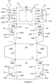
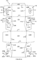
- Figure 1 shows a plan view of a blank 10 capable of forming a carton 90, as shown in Figure 2 , for primary products such as, but not limited to, bottles, hereinafter referred to as articles B.
- the terms “carton” and “carrier” refer, for the non-limiting purpose of illustrating the various features of the invention, to a container for engaging, carrying, and/or dispensing articles, such as product containers. It is contemplated that the teachings of the invention can be applied to various product containers, which may or may not be tapered and/or cylindrical. Exemplary containers include bottles (for example metallic, glass or plastics bottles), cans (for example aluminium cans), tins, pouches, packets and the like.
- suitable substrate includes all manner of foldable sheet material such as paperboard, corrugated board, cardboard, plastic, combinations thereof, and the like. It should be recognized that one or other numbers of blanks may be employed, where suitable, for example, to provide the carrier structure described in more detail below.
- the blanks are configured to form a carton or carrier for packaging an exemplary arrangement of exemplary articles.
- the arrangement is a 3 x 4 matrix or array and the articles are bottles.
- the blank can be alternatively configured to form a carrier for packaging other types, number and size of article and/or for packaging articles in a different arrangement or configuration.
- the blank 10 comprises a plurality of main panels 12, 14, 16, 18, 20 hinged one to the next in a linear series.
- the blank 10 comprises a glue panel 12 hinged to a top panel 14 by a fold line 13.
- the top panel 14 is hinged to a first side panel 16 by a fold line 15.
- the first side panel 16 is hinged to a bottom panel 18 by a fold line 17.
- the bottom panel 18 is hinged to a second side panel 20 by a fold line 19.
- the plurality of main panels 12, 14, 16, 18, 20 of the blank 10 form an open-ended tubular structure when in a set-up condition.
- Each of the ends of the tubular structure is at least partially closed by end closure panels.
- the ends of the tubular structure are fully closed by end closure panels 26A, 28A, 30A, 32A, 26b, 28B, 30B, 32B.
- End closure panels 26A, 28A, 30A, 32A are configured to close a first end of the tubular structure and end panels 26b, 28B, 30B, 32B are configured to close a second end of the tubular structure.
- a first top end closure panel 26A is hinged to a first end of top panel 14 by a fold line 27a.
- a first side end closure panel 28A is hinged to a first end of first side panel 16 by a pair of fold lines 29a, 29B.
- a first bottom end closure panel 30A is hinged to a first end of bottom panel 18 by a fold line 31A.
- a second side end closure panel 32A is hinged to a first end of the second side panel 20 by a pair of fold lines 33A, 33B.
- the pair of fold lines 29a, 29B define a first corner panel 16A disposed between the first side panel 16 and the first side end closure panel 28A.
- the pair of fold lines 33A, 33B define a second corner panel 20A disposed between the second side panel 20 and the second side end closure panel 32A.
- a second top end closure panel 26b is hinged to a second end of top panel 14 by a fold line 27B.
- a third side end closure panel 28B is hinged to a second end of the first side panel 16 by a pair of fold lines 29c, 29d.
- a second bottom end closure panel 30B is hinged to a second end of bottom panel 18 by a fold line 31B.
- a fourth side end closure panel 32B is hinged to a second end of second side panel 20 by a pair of fold lines 33c, 33d.
- the pair of fold lines 29c, 29d define a third corner panel 16B disposed between the first side panel 16 and the third side end closure panel 28B.
- the pair of fold lines 33c, 33d define a fourth corner panel 20B disposed between the second side panel 20 and the fourth side end closure panel 32B.
- the first side end closure panel 28A and the second side end closure panel 32A each form a minor side end closure panel.
- the third side end closure panel 28B and the fourth side end closure panel 32B form a minor side end closure panel.
- the first top end closure panel 26A and the second top end closure panel 26B each form a major upper end closure panel.
- the first bottom end closure panel 30A and the second bottom end closure panel 30B each form a major lower end closure panel.
- the first side end closure panel 28A comprises a fold line 21A extending between fold line 29a and a free end edge of the first side end closure panel 28A.
- the first side end closure panel 28A can be folded about fold line 21A when closing the end of the carton 90.
- the second side end closure panel 32A comprises a fold line 25A extending between fold line 33A and a free end edge of the second side end closure panel 32A.
- the second side end closure panel 32A can be folded about fold line 25A when closing the end of the carton 90.
- the third side end closure panel 28B comprises a fold line 21B extending between fold line 29d and a free end edge of the third side end closure panel 28B.
- the third side end closure panel 28B can be folded about fold line 21B when closing the end of the carton 90.
- the fourth side end closure panel 32B comprises a fold line 25B extending between fold line 33d and a free end edge of the fourth side end closure panel 32B.
- the fourth side end closure panel 32B can be folded about fold line 25B when closing the end of the carton 90.
- the top panel 14 comprises an access device Z.
- the access device Z comprises a first gate panel 24A and a second gate panel 24B.
- the first gate panel 24A is hinged to the top panel 14 by a fold line 23A.
- the second gate panel 24B is hinged to the top panel 14 by a fold line 23B.
- the first and second gate panels 24A, 24B are arranged in opposition to one another.
- the first and second gate panels 24A, 24B are severably coupled to one another; the first and second gate panels 24A, 24B share a common inner edge defined by a severance line 23c.
- the first gate panel 24A and the second gate panel 24B are further defined by a first severance line 23d and a second severance line 23e.
- the first severance line 23d extends between a first end of the fold line 23A and a first end of the fold line 23B.
- the second severance line 23e extends between a second end of the fold line 23A and a second end of the fold line 23B.
- the common severance line 23c extends between the first severance line 23d and the second severance line 23e.
- the blank 10 comprises a first handle structure H1 in the first top end closure panel 26A, and a second handle structure H2 in the second top end closure panel 26B.
- Each of the handle structures H1, H2 is substantially the same in construction, and comprises a pair of adjoining hand flaps or tabs; a first hand tab 42A and a second hand tab 42B are struck from the respective one of the first top end closure panel 26A or second top end closure panel 26B.
- the first top end closure panel 26A and/or second top end closure panel 26B each form a substantially upright handle panel.
- the first hand tab 42A is hinged along an upper edge to the respective one of the first top end closure panel 26A or second top end closure panel 26B by a hinged connection in the form of a first fold line 41A.
- the second hand tab 42B is hinged along an upper edge to the respective one of the first top end closure panel 26A or second top end closure panel 26B by a hinged connection in the form of a second fold line 41B.
- the first and second fold lines 41A, 41B are arranged to form an inverted V shape.
- the first and second fold lines 41A, 41B are convergently arranged with respect to one another and define an obtuse angle therebetween.
- Each of the first and second hand tabs 42A, 42B is defined in part by a portion of a U-shaped cutline or severance line 48.
- the first hand tab 42A is disposed adjacent to the second hand tab 42B.
- the first hand tab 42A and the second hand tab 42B share a common edge defined by a severance line or cut line 43.
- Each of the hinged connections, first and second fold lines 41A, 41B have a longitudinal axis which, in the illustrated embodiment of Figures 1-5 , is coincidental with that fold line.
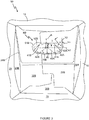
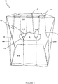
- the longitudinal axis of each hinged connection 41A, 41B is disposed at an acute angle ( ⁇ + ⁇ ), less than 90°, with respect to a notional vertical axis N2 ( Figure 3 ).
- the longitudinal axes of the hinged connections define an obtuse angle ⁇ therebetween and extend divergently downwards from the converging point of the hinged connections 41A, 41B ( Figure 2 ).
- the first hand tab 42A comprises a first flap fold line 45A and the second hand tab 42B comprises a second flap fold line 45B.
- the first and second flap fold lines 45A, 45B facilitate folding of a first portion of the respective first or second hand tab 42A, 42B with respect to a second portion of the first or second hand tabs 42A, 42B.
- the first and second flap fold lines 45A, 45B are arranged to form an inverted V shape.
- the first and second flap fold lines 45A, 45B are convergently arranged with respect to one another and define an acute or obtuse angle therebetween.
- the first and second flap fold lines 45A, 45B provide that adjacent lower corners of the first and second hand tabs 42A, 42B can be folded with respect to the rest of the respective one of the first or second hand tabs 42A, 42B.
- first hand tab 42A and the second hand tab 42B together define a single hand opening HA ( Figures 4 and 5 ) when the first and second hand tabs 42A, 42B are folded inward of the carton, out of the plane of the first top end closure panel 26A or the second top end closure panel 26B.
- the hand opening HA provides a carrying handle for a user to insert their hand into the carton 90.
- the first and second hand tabs 42A, 42B provide cushioning flaps when folded internally of the carton 90 so as to provide a comfortable handle.
- the first side end closure panel 28A comprises a first inner opening such as a cutaway or recess R1 struck from an end edge thereof.
- the first recess R1 is configured such that it is in alignment or registry with the second hand tab 42B of the first handle structure H1 or the hand opening HA of the first handle structure H1.
- the first recess R1 is defined in part by a first inner tab 52A hinged to the first side end closure panel 28A by a fold line 51A.
- the second side end closure panel 32A comprises a second inner opening such as a cutaway or recess R2 struck from an end edge thereof.
- the second recess R2 is configured such that it is in alignment or registry with the first hand tab 42A of the first handle structure H1, or the hand opening HA of the first handle structure H1.
- the second recess R2 is defined in part by a second inner tab 52B hinged to the second side end closure panel 32A by a fold line 51B.
- the third side end closure panel 28B comprises a third inner opening such as a cutaway or recess R3 struck from an end edge thereof.
- the third recess R3 is configured such that it is in alignment or registry with the second hand tab 42B of the second handle structure H2, or the hand opening HA of the second handle structure H2.
- the third recess R3 is defined in part by a first inner tab 52A hinged to the third side end closure panel 28B by a fold line 51A.
- the fourth side end closure panel 32B comprises a fourth inner opening such as a cutaway or recess R4 struck from an end edge thereof.
- the fourth recess R4 is configured such that it is in alignment or registry with the first hand tab 42A of the second handle structure H2, or the hand opening HA of the second handle structure H2.
- the fourth recess R4 is defined in part by a second inner tab 52B hinged to the fourth side end closure panel 32B by a fold line 51B.
- the carton 90 may be formed by a series of sequential folding operations in a straight line machine such that the carton 90 is not required to be rotated or inverted to complete its construction.
- the folding process is not limited to that described below and may be altered according to particular manufacturing requirements.
- the blank 10 is folded about fold line 15, such that the glue panel 12 and top panel 14 are folded thereabouts.
- the top panel 14 is brought into face contacting relationship with the first side panel 16; the glue panel 12 is brought into face contacting relationship with the first side panel 16 and/or bottom panel 18.
- Glue or other adhesive treatment is applied to the glue panel 12 or, in alternative embodiments, to a corresponding portion of the second side panel 20.
- the second side panel 20 is folded about the fold line 19 such that the second side panel 20 overlies the glue panel 12.
- the second side panel 20 is secured to the glue panel 12 to form a flat collapsed carton.
- the carton may be shipped or distributed in this flat collapsed form.
- the second side panel 20 may be secured to the glue panel 12 by alternative securing means for example, but not limited to, staples or other mechanical fixing means.
- the flat collapsed carton may be erected into a tubular structure by separating the top panel 14 from the bottom panel 18.
- the carton 90 in its open-ended tubular form, may be loaded with articles B through one or both open ends. It will be appreciated that in other embodiments one of the open ends of the carton 90 may be closed before loading the carton 90 with articles B through the remaining open end.
- one or more of the end closure panels 26A, 28A, 30A, 32A, 26B, 28B, 30B, 32B are folded outwardly so as to create a funnel at one or both of the open ends of the tubular structure for facilitating loading of the carton with articles B.
- a first end of the tubular structure is closed by folding the second and second side end closure panels 28A, 32A about fold lines 29A, 33A respectively.
- Glue or other adhesive treatment may be applied to the first side end closure panel 28A, or in alternative embodiments, to a corresponding portion of the first top end closure panel 26A.
- Glue or other adhesive treatment may be applied to the second side end closure panel 32A, or in alternative embodiments, to a corresponding portion of the first top end closure panel 26A.
- the first top end closure panel 26A is then folded about the fold line 27A to be brought into contact with the second and second side end closure panels 28A, 32A and optionally secured thereto.
- Glue or other adhesive treatment may be applied to the first side end closure panel 28A, or in alternative embodiments, to a corresponding portion of the first bottom end closure panel 30A.
- Glue or other adhesive treatment may be applied to the second side end closure panel 32A, or in alternative embodiments, to a corresponding portion of the first bottom end closure panel 30A.
- Glue or other adhesive treatment is applied to an inner surface of the first bottom end closure panel 30A, or in alternative embodiments, to an outer surface of the first top end closure panel 26A.
- the first bottom end closure panel 30A is then folded about the fold line 31A to be brought into contact with the second and second side end closure panels 28A, 32A and the first top end closure panel 26A.
- the first bottom end closure panel 30A is secured to the first top end closure panel 26A.
- the first bottom end closure panel 30A is secured to the second and second side end closure panels 28A, 32A.
- first bottom end closure panel 30A may be folded about fold line 31A prior to folding the first top end closure panel 26A about fold line 27A. It will be appreciated that in such embodiments the first top end closure panel 26A is disposed outermost.
- a second end of the tubular structure is closed by folding the sixth and fourth side end closure panels 28B, 32B about fold lines 29d, 33d respectively.
- Glue or other adhesive treatment may be applied to the third side end closure panel 28B, or in alternative embodiments, to a corresponding portion of the second top end closure panel 26B.
- Glue or other adhesive treatment may be applied to the fourth side end closure panel 32B, or in alternative embodiments, to a corresponding portion of the second top end closure panel 26B.
- the second top end closure panel 26B is then folded about the fold line 27B to be brought into contact with the sixth and fourth side end closure panels 28B, 32B and optionally secured thereto.
- Glue or other adhesive treatment may be applied to the third side end closure panel 28B, or in alternative embodiments, to a corresponding portion of the second bottom end closure panel 30B.
- Glue or other adhesive treatment may be applied to the fourth side end closure panel 32B, or in alternative embodiments to a corresponding portion of the second bottom end closure panel 30B.
- Glue or other adhesive treatment is applied to an inner surface of the second bottom end closure panel 30B, or in alternative embodiments, to an outer surface of the second top end closure panel 26B.
- the second bottom end closure panel 30B is then folded about the fold line 31B to be brought into contact with the sixth and fourth side end closure panels 28B, 32B and the second top end closure panel 26B.
- the second bottom end closure panel 30B is secured to the second top end closure panel 26B.
- the second bottom end closure panel 30B is secured to the sixth and fourth side end closure panels 28B, 32B.
- the second bottom end closure panel 30B may be folded about fold line 31B prior to folding the second top end closure panel 26B about fold line 27B. It will be appreciated that in such embodiments the second top end closure panel 26B is disposed outermost.
- a user inserts at least a portion of their hand into a hand opening HA created by folding the first and second hand tabs 42A, 42B of the first handle structure H1 and/or second handle structure H2 internally of the carton 90 as shown in Figures 4 and 5 .
- the first and second inner tabs 52A, 52B of the respective one of the first and second handle structures H1, H2 are folded internally of the carton about fold lines 51A, 51B.
- the fold line 51A and the fold line 41A are arranged divergently with respect to each other.
- the fold line 51A is arranged such that it does not overlie, or intersect with, the fold line 41A.
- the fold line 51A is disposed above the fold line 41A with their respective lower ends positioned on a notional horizontal line N1 and spaced from each other.
- the fold lines 51A, 41A extend upwardly divergently from their respective lower ends toward the top panel 14.
- the fold line 51A and the fold line 41A are arranged to define an acute angle ⁇ with respect to each other.
- the fold line 51A is arranged to define an acute angle ⁇ with respect to the notional horizontal line N1.
- the acute angle ⁇ is substantially greater than the acute angle ⁇ .
- the fold line 51A is arranged to define an acute angle ⁇ with respect to a notional vertical line N2 perpendicular to the notional horizontal line N1.
- the fold line 41A is arranged to define an acute angle ⁇ with respect to the notional horizontal line N1.
- the angle ⁇ is less than the angle ⁇ and may optionally be less than angle ⁇ .
- the angle ⁇ may be between approximately 25° to 30°; for example, in one embodiment the angle ⁇ is approximately 28.5°.
- the angle ⁇ may be between approximately 40° to 60° ; for example, in one embodiment the angle ⁇ is approximately 50°.
- the angle ⁇ may be between approximately 10° to 35°; for example, in one embodiment the angle ⁇ is approximately 21.5°.
- the first hand tab 42A is arranged in a partially overlapping or overlying relationship with the first inner tab 52A.
- the second hand tab 42B is arranged in a partially overlapping or overlying relationship with the second inner tab 52B.
- the fold line 51A is disposed above the fold line 41A.
- the fold line 51B is disposed above the fold line 41B.
- the arrangement of the second hand tab 42B with respect to the second inner tab 52B is substantially the same as the arrangement of the first hand tab 42A with respect to the first inner tab 52A described above, albeit a mirror image of the arrangement of the first hand tab 42A and the first inner tab 52A.
- the fold line 51B and the fold line 41B are arranged divergently with respect to each other.
- the fold line 51B is arranged such that it does not overlie, or intersect with, the fold line 41B.
- the fold line 51B is disposed above the fold line 41B with their respective lower ends positioned on a notional horizontal line and spaced from each other.
- the fold lines 51B, 41B extend upwardly divergently from their respective lower ends toward the top panel 14.
- the fold line 51B and the fold line 41B are arranged to define an acute angle with respect to each other, as shown in Figure 3 .
- the fold line 51B is arranged to define an acute angle with respect to a notional horizontal line.
- the fold line 51B is arranged to define an acute angle with respect to a notional horizontal line.
- the fold line 41B is arranged to define an acute angle with respect to a notional horizontal line.
- the carton 90 comprises rows of articles B, optionally three articles B.
- a central article B is disposed substantially in the middle of the carton 90, and the handle structures H1, H2 are also disposed centrally between the side walls 16, 20.
- an article B is disposed centrally with respect to the hand opening HA created by folding the first and second hand tabs 42A, 42B.
- the arrangement of the handle structures H1, H2 allows the first and second hand tabs 42A, 42B to be folded on opposing sides of the centrally located article B.
- Figure 5 shows an internal view of the carton 90; a user U has partially inserted a hand through the hand opening HA created by folding the first and second hand tabs 42A, 42B of the first handle structure H1.
- the fold lines 45A, 45B facilitate folding of the first and second hand tabs 42A, 42B respectively about the central article B.
- the corner portions C1, C2 of the first and second hand tabs 42A, 42B fold about fold lines 45A, 45B when the corner portions C1, C2 come into contact with the central article B, best shown in the internal view of Figure 5 , in which the articles B have been omitted for clarity.
- Figure 6 shows a plan view of a blank 110 according to a second embodiment.
- the blank 110 comprises a plurality of main panels 112, 114, 116, 118, 120 hinged one to the next in a linear series.
- the blank 110 comprises a glue panel 112 hinged to a top panel 114 by a fold line 113.
- the top panel 114 is hinged to a first side panel 116 by a fold line 115.
- the first side panel 116 is hinged to a bottom panel 118 by a fold line 117.
- the bottom panel 118 is hinged to a second side panel 120 by a fold line 119.
- the plurality of main panels 112, 114, 116, 118, 120 of the blank 110 form an open-ended tubular structure when in a set-up condition.
- Each of the ends of the tubular structure is at least partially closed by end closure panels.
- the ends of the tubular structure are fully closed by end closure panels 126A, 128A, 130A, 132A, 126B, 128B, 130B, 132B.
- End closure panels 126A, 128A, 130A, 132A are configured to close a first end of the tubular structure and end panels 126B, 128B, 130B, 132B are configured to close a second end of the tubular structure.
- the blank 110 comprises a first handle structure H1 in a first top end closure panel 126A, and a second handle structure H2 in a second top end closure panel 126B.
- Each of the handle structures H1, H2 is substantially the same in construction, and comprises a first hand tab 142A and a second hand tab 142B struck from the respective one of the first top end closure panel 126A or second top end closure panel 126B.
- the first hand tab 142A is hinged along an upper edge to the respective one of the first top end closure panel 126A or second top end closure panel 126B by a first fold line 141A.
- the second hand tab 142B is hinged along an upper edge to the respective one of the first top end closure panel 126A or second top end closure panel 126B by a second fold line 141B.
- the first and second fold lines 141A, 141B are arranged to form an inverted V-shape.
- the first and second fold lines 141A, 141B are convergently arranged with respect to one another and define an obtuse angle therebetween.
- Each of the first and second hand tabs 142A, 142B is defined in part by cut lines or severance lines 148A, 148B and in part by an aperture A1.
- the aperture A1 is substantially triangular in shape, although other shapes may be employed in alternative embodiments.
- the first hand tab 142A is disposed adjacent to the second hand tab 142B.
- the first hand tab 142A and the second hand tab 142B share a common edge defined by a severance line or cut line 143.
- the common severance line or cut line 143 extends from the aperture A1 to a vertex at which first and second fold lines 141A, 141B meet.
- first hand tab 142A, second hand tab 142B and aperture A1 define a hand opening HA when the first and second hand tabs 142A, 142B are folded out of the plane of the first top end closure panel 126A or the second top end closure panel 126B.
- the hand opening HA provides a carrying handle for a user to insert their hand into a carton 190, see Figure 7A .
- the first and second hand tabs 142A, 142B provide cushioning flaps when folded internally of the carton 190 so as to provide a comfortable handle.
- the first side end closure panel 128A comprises a first inner opening such as a cutaway or recess R1 struck from an end edge thereof.
- the first recess R1 is configured such that it is in alignment or registry with the second hand tab 142B of the first handle structure H1 or the hand opening defined by the tabs 142A, 142B of the first handle structure H1.
- the first recess R1 is defined in part by a first inner tab 152A hinged to the first side end closure panel 128A by a fold line 151A.
- the second side end closure panel 132A comprises a second inner opening such as a cutaway or recess R2 struck from an end edge thereof.
- the second recess R2 is configured such that it is in alignment or registry with the first hand tab 142A of the first handle structure H1, or the hand opening HA ( Figure 7B ) defined by the tabs 142A, 142B of the first handle structure H1.
- the second recess R2 is defined in part by a second inner tab 152B hinged to the second side end closure panel 132A by a fold line 151B.
- the third side end closure panel 128B comprises a third inner opening such as a cutaway or recess R3 struck from an end edge thereof.
- the third recess R3 is configured such that it is in alignment or registry with the second hand tab 142B of the second handle structure H2, or the hand opening HA defined by the tabs 142A, 142B of the second handle structure H2.
- the third recess R3 is defined in part by a first inner tab 152A hinged to the third side end closure panel 128B by a fold line 151A.
- the fourth side end closure panel 132B comprises a fourth inner opening such as a cutaway or recess R4 struck from an end edge thereof.
- the fourth recess R4 is configured such that it is in alignment or registry with the first hand tab 142A of the second handle structure H2 or the hand opening HA defined by the tabs 142A, 142B of the second handle structure H2.
- the fourth recess R4 is defined in part by a second inner tab 152B hinged to the fourth side end closure panel 132B by a fold line 151B.
- Figure 7A shows a partial view of an end of a carton 190 in which the carrying handle is in a stowed or undeployed condition.
- Figure 7B shows a partial view of an end of the carton 190 in which the first and second hand tabs 142A, 142B of the carrying handle have been folded outwardly of the carton 190 as indicated by direction arrows D1, D2 respectively.
- the first and second hand tabs 142A, 142B have been folded outwardly for illustrative purposes only; in use the first and second hand tabs 142A, 142B of the carrying handle will be folded internally or inwardly of the carton 190.
- Figure 7B illustrates the position and orientation of the first and second inner tabs 152A, 152B.
- the first and second inner tabs 152A, 152B are located internally with respect to first and second inner tabs 152A, 152B. It will be appreciated from Figure 7B that the first hand tab 142A partially overlaps or overlays the first inner tab 152A, and that the second hand tab 142B partially overlaps or overlays the second inner tab 152B.
- Figure 8 shows a plan view of a blank 210 according to a third embodiment.
- the blank 210 comprises a plurality of main panels 212, 214, 216, 218, 220 hinged one to the next in a linear series.
- the blank 210 comprises a glue panel 212 hinged to a top panel 214 by a fold line 213.
- the top panel 214 is hinged to a first side panel 216 by a fold line 215.
- the first side panel 216 is hinged to a bottom panel 218 by a fold line 217.
- the bottom panel 218 is hinged to a second side panel 220 by a fold line 219.
- the plurality of main panels 212, 214, 216, 218, 220 of the blank 210 form an open-ended tubular structure when in a set-up condition.
- Each of the ends of the tubular structure is at least partially closed by end closure panels.
- the ends of the tubular structure are fully closed by end closure panels 226A, 228A, 230A, 232A, 226B, 228B, 230B, 232B.
- End closure panels 226A, 228A, 230A, 232A are configured to close a first end of the tubular structure and end panels 226B, 228B, 230B, 232B are configured to close a second end of the tubular structure.
- the blank 210 comprises a first handle structure H1 in a first top end closure panel 226A and a second handle structure H2 in a second top end closure panel 226B.
- Each of the handle structures H1, H2 is substantially the same in construction, and comprises a first hand tab 242A and a second hand tab 242B struck from the respective one of the first top end closure panel 226A or second top end closure panel 226B.
- the first hand tab 242A is hinged to the respective one of the first top end closure panel 226A or second top end closure panel 226B by a pair of fold lines 270A, 270B.
- the second hand tab 242B is hinged the respective one of the first top end closure panel 226A or second top end closure panel 226B by a pair of fold lines 270A, 270B.
- the pairs of fold lines 270A, 270B are non-linear in shape; in the illustrated embodiment the fold lines 270A, 270B are arcuate in shape.
- the fold lines 270A, 207B converge towards each other at both ends thereof to form a vertex or point of intersection at each end.
- the fold lines 270A, 207B together define web panel 276 which in the illustrated embodiment has a pointed oval or pointed elliptical shape.
- the web panel 276 comprises a fold line 272 which bisects the web panel 276 into a first part 274A and a second part 274B.
- the web panel 276 comprises a first vertex defined by first ends of the fold lines 270A, 270B.
- the web panel 276 comprises a second vertex defined by second ends of the fold lines 270A, 270B.
- the first and second vertices of the web panel 276 hinged to the first hand tab 242A define a first notional linear line L1 as shown in Figure 9 .
- the first and second vertices of the web panel 276 hinged to the second hand tab 242B define a second notional linear line L2.
- the first and second notional linear lines L1, L2 are arranged to form an inverted V-shape.
- the first and second notional linear lines L1, L2 define an obtuse angle ⁇ therebetween.
- the first hand tab 242A is defined in part by cut lines or severance lines 248A, 248c, fold line 270B and in part by an aperture A1.
- the second hand tab 242B is defined in part by cut lines or severance lines 248B, 248d, fold line 270B and in part by an aperture A1.
- the aperture A1 is substantially triangular in shape, although other shapes may be employed in alternative embodiments.
- the first hand tab 242A is disposed adjacent to the second hand tab 242B.
- the first hand tab 242A and the second hand tab 242B share a common edge defined by a severance line or cut line 243.
- the common severance line or cut line 243 extends from the aperture A1 to a vertex at which first and second fold lines 241A, 241B meet.
- the cut lines or severance lines 248A, 248B are interrupted by nick portions or connecting portions N1, N2 respectively.
- the connecting portions N1, N2 facilitate maintenance of the first and second hand tabs 242A, 242B in the plane of the first top end closure panel 226A or second top end closure panel 226B until the carrying handle is employed.
- the web panel 276 and the fold lines 270A, 270B are substantially equivalent to the linear fold lines 41A, 41B; 141A, 141B used in the previously described embodiments, providing means for the first and second hand tabs 242A, 242B to fold when the carrying handle is employed.
- the first and second hand tabs 242A, 242B are foldable about the first and second notional linear lines L1, L2.
- the area occupied by the first hand tab 242A, second hand tab 242B and aperture A1 defines a hand opening HA when the first and second hand tabs 242A, 242B are folded out of the plane of the first top end closure panel 226A or the second top end closure panel 226B.
- the hand opening HA provides a carrying handle for a user to insert their hand into a carton 290.
- the first and second hand tabs 242A, 242B provide cushioning flaps when folded internally of the carton 290 so as to provide a comfortable handle.
- the first side end closure panel 228A comprises a first inner opening such as a cutaway or recess R1 struck from an end edge thereof.
- the first recess R1 is configured such that it is in alignment or registry with the second hand tab 242B of the first handle structure H1, or the hand opening HA the first handle structure H1.
- the first recess R1 is defined in part by a pair of conjoined first inner tabs 262A, 264A which are hinged to the first side end closure panel 228A by a common fold line 261A.
- the fold line 261A is non-linear in shape, and may, for example as illustrated, be arcuate or curvilinear in shape.
- the two first hand tabs 262A, 264A are joined together through a narrowed portion having a concaved outline which is spaced apart from the common fold line 261A.
- the concaved outline of the narrowed portion may in contact or intersect with the fold line 261A to divide the inner tabs 262A, 264A into two substantially separated tabs.
- the second side end closure panel 232A comprises a second inner opening such as a cutaway or recess R2 struck from an end edge thereof.
- the second recess R2 is configured such that it is in alignment or registry with the first hand tab 242A of the first handle structure H1, or the hand opening HA of the first handle structure H1.
- the second recess R2 is defined in part by a pair of second inner tabs 262B, 264B which are hinged to the first side end closure panel 232A by a common fold line 261B.
- the fold lines 261B is non-linear in shape, and may, for example as illustrated, be arcuate or curvilinear in shape.
- the two first hand tabs 262B, 264B are joined together through a narrowed portion having a concaved outline which is spaced apart from the common fold line 261B.
- the concaved outline of the narrowed portion may contact or intersect with the fold line 261B to divide the inner tabs 262B, 264B into two substantially separated tabs.
- the third side end closure panel 228B comprises a third inner opening such as a cutaway or recess R3 struck from an end edge thereof.
- the third recess R3 is configured such that it is in alignment or registry with the second hand tab 242B of the second handle structure H2, or the hand opening HA of the second handle structure H2.
- the third recess R3 is defined in part by a pair of first inner tabs 262A, 264A which are hinged to the first side end closure panel 228B by a common fold line 261A.
- the fold line 261A is non-linear in shape, and may, for example as illustrated, be arcuate or curvilinear in shape.
- the two first hand tabs 262A, 264A of the second handle structure H2 are joined together through a narrowed portion having a concaved outline which is spaced apart from the common fold line 261A.
- the concaved outline of the narrowed portion may contact or intersect with the fold line 261A6 to divide the inner tabs 262A, 264A into two substantially separated tabs.
- the fourth side end closure panel 232B comprises a fourth inner opening such as a cutaway or recess R4 struck from an end edge thereof.
- the fourth recess R4 is configured such that it is in alignment or registry with the first hand tab 242A of the second handle structure H2, or the hand opening HA of the second handle structure H2.
- the fourth recess R4 is defined in part by a pair of second inner tabs 262B, 264B which is hinged to the first side end closure panel 232B by a common fold line 261B.
- the fold line 261B is non-linear in shape, and may, for example as illustrated, be arcuate or curvilinear in shape.
- the two first hand tabs 262B, 264B of the second handle structure H2 are joined together through a narrowed portion having a concaved outline which is spaced apart from the common fold line 261B.
- the concaved outline of the narrowed portion may contact or intersect with the fold lines 261B to divide the inner tabs 262B, 264B into two substantially separated tabs.
- each of the pair of first inner tabs 262A, 264A comprises a substantially oval shape having one pointed end as best shown in Figures 10 and 11 , although in other embodiments other shapes may be employed.
- each of the first inner tabs 262A, 264A may have a substantially oval shape having a pair of opposed pointed ends such that the first inner tabs 262A, 264A are not coupled together but in contact with each other at their adjacent pointed ends.
- the pair of the first inner tabs 262A, 264A together form a single tab having a pair of lobes 262A, 264A, each of the lobes having a substantially oval shape having one pointed end.
- each of the pair of second inner tabs 262B, 264B comprises a substantially oval shape having one pointed end as best shown in Figures 10 and 11 , although in other embodiments other shapes may be employed.
- each of the first inner tabs 262B, 264B may have a substantially oval shape having a pair of opposed pointed ends such that the second inner tabs 262B, 264B are not coupled together but in contact with each other at their adjacent pointed ends.
- the pair of the second inner tabs 262B, 264B form a single tab having a pair of lobes 262B, 264B, each of the lobes having a substantially oval shape having one pointed end.
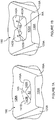
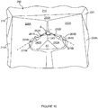
- Figure 10 shows an internal view of the carrying handle structure.
- the pair of second inner tabs 262B, 264B are in overlapping or overlaying relationship with the web panel 276 hinged to the first hand tab 242A.
- the pair of first inner tabs 262A, 264A is in overlapping or overlaying relationship with the web panel 276 hinged to the first hand tab 242B.
- the pair of first inner tabs 262A, 264A and the pair of second inner tabs 262B, 264B each provide a mandrel for guiding or facilitating folding of the respective web panel 276 when the carrying handle is deployed.
- the first inner tabs 262A, 264A and the second inner tabs 262B, 264B encourage the web panel 276 to bend about the fold line 272 such that it takes a convex shape when viewed from an internal vantage point above the carrying handle structure, as shown in Figure 11 . In this way the web panel 276 adopts a non-planar form.
- the web panel 276 When viewing the outer external surface of the sheet material from which the carton 290 is formed, the web panel 276 will have a concave shape; the web panel 276 may, in some embodiments, be valley shaped, that is to say forming a trough having a "V"-shaped cross section. This enhances the strength of the web panel 276 and prevents or mitigates against the web panel 276 folding about itself about a longitudinal axis of the web panel 276 defined by the first or second linear notional line L1, L2.
- Figure 12 shows a plan view of a blank 310 according to a third embodiment.
- the blank 310 comprises a plurality of main panels 312, 314, 316, 318, 320 hinged one to the next in a linear series.
- the blank 310 comprises a glue panel 312 hinged to a top panel 314 by a fold line 313.
- the top panel 314 is hinged to a first side panel 316 by a fold line 315.
- the first side panel 316 is hinged to a bottom panel 318 by a fold line 317.
- the bottom panel 318 is hinged to a second side panel 320 by a fold line 319.
- the plurality of main panels 312, 314, 316, 318, 320 of the blank 310 form an open-ended tubular structure when in a set-up condition.
- Each of the ends of the tubular structure is at least partially closed by end closure panels.
- the ends of the tubular structure are fully closed by end closure panels 326A, 328A, 330A, 332A, 326B, 328B, 330B, 332B.
- End closure panels 326A, 328A, 330A, 332A are configured to close a first end of the tubular structure and end panels 326B, 328B, 330B, 332B are configured to close a second end of the tubular structure.
- the blank 310 comprises a first handle structure H1 in a first top end closure panel 326A and a second handle structure H2 in a second top end closure panel 326B.
- Each of the handle structures H1, H2 is substantially the same in construction, and comprises a first hand tab 342A and a second hand tab 342B struck from the respective one of the first top end closure panel 326A or second top end closure panel 326B.
- the first hand tab 342A is hinged to the respective one of the first top end closure panel 326A or second top end closure panel 326B by a first pair of fold lines 381A, 383A.
- the second hand tab 342B is hinged to the respective one of the first top end closure panel 326A or second top end closure panel 326B by a second pair of fold lines 381B, 383B.
- Each of the first pair of fold lines 381A, 383A are non-linear in shape; in the illustrated embodiment the fold lines 381A, 383A are arcuate in shape.
- the fold lines 381A, 383A converge towards each other at both ends thereof to form a vertex or point of intersection at each end.
- the fold lines 381A, 383A together define first web panel 376A which in the illustrated embodiment has a pointed oval shape.
- the first web panel 376A comprises a first vertex defined by first ends of the fold lines 381A, 383A.
- the first web panel 376A comprises a second vertex defined by second ends of the fold lines 381A, 383A.
- the first and second vertices of the first web panel 376A hinged to the first hand tab 342A define a first notional linear line L1.
- Each of the second pair of fold lines 381B, 383B are non-linear in shape; in the illustrated embodiment the fold lines 381B, 383B are arcuate in shape.
- the fold lines 381B, 383B converge towards each other at both ends thereof to form a vertex or point of intersection at each end.
- the fold lines 381B, 383B together define second web panel 376B which in the illustrated embodiment has a pointed oval shape.
- the second web panel 376B comprises a first vertex defined by first ends of the fold lines 381B, 383B.
- the second web panel 376B comprises a second vertex defined by second ends of the fold lines 381B, 383B.
- the first and second vertices of the second web panel 376B hinged to the second hand tab 342B define a second notional linear line L2.
- the first and second notional linear lines L1, L2 are arranged to form an inverted V shape.
- the first and second notional linear lines L1, L2 define an obtuse angle ⁇ therebetween.
- the first hand tab 342A is defined in part by fold line 383A and in part by a portion of a U-shaped cut line or severance line 348.
- the second hand tab 342B is defined in part by fold line 383B and in part by a portion of the U-shaped cut line or severance line 348.
- the first hand tab 342A is disposed adjacent to the second hand tab 342B.
- the first hand tab 342A and the second hand tab 342B share a common edge defined by a severance line or cut line 343.
- the common severance line or cut line 343 extends from the U-shaped cut line or severance line 348 to a vertex at which fold line 383A meets fold line 383B.
- the first hand tab 342A comprises a first flap fold line 345A and the second hand tab 342B comprises a second flap fold line 345B.
- the first and second flap fold lines 345A, 345B facilitate folding of a first portion of the respective first or second hand tab 342A, 342B with respect to a second portion of the first or second hand tab 342A, 342B.
- the first flap fold line 345A extends between the fold line 383A and the U-shaped cutline 348.
- the second flap fold line 345B extends between the fold line 383B and the U-shaped cutline 348.
- the first and second flap fold lines 345A, 345B are divergently arranged with respect to one another and define an acute angle therebetween.
- the first and second flap fold lines 345A, 345B provide that outermost portions of the first and second hand tabs 342A, 342B can be folded with respect to the rest of the respective one of the first or second hand tab 342A, 342B.
- first hand tab 342A and the second hand tab 342B together define a hand opening when the first and second hand tabs 342A, 342B are folded out of the plane of the first top end closure panel 326A or the second top end closure panel 326B.
- the hand opening provides a carrying handle for a user to insert their hand into the carton.
- the first and second hand tabs 342A, 342B provide cushioning flaps when folded internally of the carton so as to provide a comfortable handle.
- the first side end closure panel 328A comprises a first inner cut away such as a cutaway or recess R1 struck from an end edge thereof.
- the first recess R1 is configured such that it is in alignment or registry with the second hand tab 342B of the first handle structure H1, or the hand opening HA of the first handle structure H1.
- the second side end closure panel 332A comprises a second inner opening such as a cutaway or recess R2 struck from an end edge thereof.
- the second recess R2 is configured such that it is in alignment or registry with the first hand tab 342A of the first handle structure H1, or the hand opening HA of the first handle structure H1.
- the third side end closure panel 328B comprises a third inner opening such as a cutaway or recess R3 struck from an end edge thereof.
- the third recess R3 is configured such that it is in alignment or registry with the second hand tab 342B of the second handle structure H2, or the hand opening HA of the second handle structure H2.
- the fourth side end closure panel 332B comprises a fourth inner opening such as a cutaway or recess R4 struck from an end edge thereof.
- the fourth recess R4 is configured such that it is in alignment or registry with the first hand tab 342A of the second handle structure H2, or the hand opening HA of the second handle structure H2.
- the inner tabs such as 52A, 52B, have been omitted from the first, second, third and fourth recesses R1, R2, R3, R4.
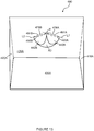
- Figure 13 shows an end view of a carton 490 according to a fifth embodiment.
- the carton 490 comprises a plurality of main panels forming a tubular structure.
- the tubular structure is closed at each end by end closure panels 416A, 420A, 426A, 430A.
- the carton 490 comprises an upper end closure panel 426A having a handle structure defined therein.
- the handle structure comprises a first hand tab 442A and a second hand tab 442B.
- the first hand tab 442A is hinged to the upper end closure panel 426A by a pair of non-linear fold lines 491A, 493A.
- the fold lines 491A, 493A are arcuate in shape.
- the fold lines 491A, 493A converge towards each other at both ends thereof to form a vertex or point of intersection at each end.
- the fold lines 491A, 493A together define web panel 476A which, in the illustrated embodiment, has a pointed oval shape.
- the web panel 476A comprises a first vertex defined by first ends of the fold lines 491A, 493A.
- the web panel 476A comprises a second vertex defined by second ends of the fold lines 491A, 493A.
- the first and second vertices of the web panel 476A hinged to the first hand tab 442A define a first notional linear line L1.
- the second hand tab 442B is hinged to the upper end closure panel 426A by a pair of non-linear fold lines 491B, 493B.
- the fold lines 491B, 493B are arcuate in shape.
- the fold lines 491B, 493B converge towards each other at both ends thereof to form a vertex or point of intersection at each end.
- the fold lines 491B, 493B together define web panel 476B which, in the illustrated embodiment, has a pointed oval shape.
- the web panel 476B comprises a first vertex defined by first ends of the fold lines 491B, 493B.
- the web panel 476B comprises a second vertex defined by second ends of the fold lines 491B, 493B.
- the first and second vertices of the web panel 476B hinged to the second hand tab 442B define a second notional linear line L2.
- the first and second notional linear lines L1, L2 are arranged to form an inverted V-shape.
- the first and second notional linear lines L1, L2 define an obtuse angle ⁇ therebetween.
- the first hand tab 442A is separated from the second hand tab 442B by a portion of an aperture A3, which portion has an inverted "V" shape.
- a first side end closure panel 416A comprises a first inner opening such as a cutaway or recess (not shown) struck from an end edge thereof.
- the first recess is configured such that it is in alignment or registry with a portion of a hand opening defined by the first hand tab 442A, second hand tab 442B and the aperture A3.
- a second side end closure panel 420A comprises a second inner opening such as a cutaway or recess (not shown) struck from an end edge thereof.
- the second recess is configured such that it is in alignment or registry with a portion of the hand opening defined by the first hand tab 442A, second hand tab 442B and the aperture A3.
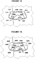
- Figure 14 shows a fragmentary internal end elevation of a carton according to a sixth embodiment.
- the carton of the sixth embodiment shares many common features with that of the first embodiment shown in Figures 1-5 and therefore only the differences from the embodiment illustrated in Figures 1 to 5 will be described in any greater detail.
- like numerals, where possible, are used to denote like parts which are also present in Figures 1-5 , albeit with the addition of the prefix "500" to indicate that these features belong to the sixth embodiment, respectively.
- the carton of the sixth embodiment includes a top panel, a bottom panel, a first side panel and a second side panel forming a tubular structure.
- Figure 14 shows a third side end closure panel 528B hingedly connected to the first side panel and a fourth side end closure panel 532B hingedly connected to the second side panel.
- the third and fourth side end closure panels 528B, 532B close a second end of the tubular structure in cooperation with the second top and bottom end closure panels.
- the third and fourth side end closure panels 528B, 532B and the second top and bottom end closure panels together provide an upright, composite end wall of the carton, which closes the second end of the tubular structure.
- Figure 14 which is a fragmentary internal elevation of the composite end wall
- the third side end closure panel 528B is the innermost layer of the composite end wall while the fourth side end closure panel 532B is the second innermost layer of the composite end wall wherein the respective free end portions of the third and fourth side end closure panels 528B, 532B are shown as overlapping with each other.
- the top end closure panel provides either the outermost or second outermost layer of the composite wall in the manner similar to what are illustrated in Figures 3 and 4 .
- a handle structure is provided by a pair of adjoining hand flaps 542A, 542B which are hingedly connected to the top end closure panel by a pair of hinged connections 541A, 541B such that the hand flaps 542A, 542B together define a single hand opening in the top end closure panel when the hand flaps 542A, 542B are folded out of the plane of the top end closure panel.
- Each of the hinged connections 541A, 541B in this embodiment is provided by a linear fold line.
- the longitudinal axis of each hinged connection is disposed at an acute angle with respect to a notional horizontal line. Such longitudinal axes of the hinged connections are coincidental with the fold lines 541A, 541B, respectively.
- the fold lines 541A, 541B meet at their common upper end and downwardly extend from the common upper end divergently from each other. An obtuse angle is defined between the fold lines 541A, 541B.
- the first hand tab 542A is defined in part by fold line 541A and in part by a portion of a U-shaped cut line or severance line 548.
- the second hand tab 542B is defined in part by fold line 541B and in part by a portion of the U-shaped cut line or severance line 548.
- the first hand tab 542A is disposed adjacent to the second hand tab 542B.
- the first hand tab 542A and the second hand tab 542B share a common edge defined by a severance line or cut line 543.
- the severance line or cut line 543 extends from the U-shaped cut line or severance line 548 to a vertex at which fold line 541A meets fold line 541B.
- the first hand tab 542A comprises a first flap fold line 545A while the second hand tab 542B comprises a second flap fold line 545B.
- the first and second flap fold lines 545A, 545B facilitate folding of a first portion of the respective first or second hand tab 542A, 542B with respect to a second portion of the first or second hand tab 542A, 542B.
- the first flap fold line 545A extends between the severance line 543 and the U-shaped cutline 548.
- the second flap fold line 545B extends between the severance line 543 and the U-shaped cutline 548.
- the first and second flap fold lines 545A, 545B converge on the severance line 453 and define an obtuse angle therebetween.
- the first and second flap fold lines 545A, 545B an apex on the severance line 543 from which the flap fold lines 545A, 545B downwardly extend divergently from each other.
- the hand opening defined by the hand flaps 542A, 542B provides a carrying handle for a user to insert their hand into the carton.
- the first and second hand tabs 542A, 542B provide cushioning flaps when folded internally of the carton so as to provide a comfortable handle.
- the third side end closure panel 528B comprises a third inner opening such as a cutaway or recess struck from an end edge thereof.
- the third inner opening is configured such that it is in alignment or registry with the first hand tab 542A, or the hand opening of the handle structure.
- the fourth side end closure panel 532B comprises a fourth inner opening such as a cutaway or recess struck from an end edge thereof.
- the fourth inner opening is configured such that it is in alignment or registry with the second hand tab 542B, or the hand opening of the handle structure.
- the third inner opening is defined in part by a first inner tab 552A hinged to the third side end closure panel 528B by a fold line 551A.
- the fourth inner opening is defined in part by a second inner tab 552B hinged to the fourth side end closure panel 532B by a fold line 551B.
- the lower end of the inner flap fold line 551A is located below the lower end of the flap fold line 541A.
- the inner flap fold line 551A extends upward from its lower end, intersects with the flap fold line 541A of the hand flap 542A and extends above the flap fold line 541A.
- the fold lines 551A, 541A are arranged to define an acute angle with respect to each other.
- the inner flap fold line 551A is arranged to define an acute angle with respect to a notional horizontal line.
- the flap fold line 541A is arranged to define an acute angle with respect to a notional horizontal line.
- the acute angle between the flap fold line 541A and the notional horizontal line is less than that between the inner flap fold line 551A and the notional horizontal line.
- the flap fold line 541A is arranged to define an acute angle with respect to a notional vertical line.
- the first hand tab 542A is arranged in a partially overlapping or overlying relationship with the first inner tab 552A.
- the second hand tab 542B is arranged in a partially overlapping or overlying relationship with the second inner tab 552B.
- the arrangement of the second hand tab 542B with respect to the second inner tab 552B is substantially the same as the arrangement of the first hand tab 542A with respect to the first inner tab 552A described above, albeit a mirror image of the arrangement of the first hand tab 542A and the first inner tab 552A.
- Figure 15 shows a fragmentary internal end elevation of a carton according to a seventh embodiment.
- the carton of the seventh embodiment shares many common features with that of the first and sixth embodiment shown in Figures 1 to 5 and 14 and therefore only the differences from the embodiments illustrated in Figures 1 to 5 and 14 will be described in any greater detail.
- like numerals, where possible, are used to denote like parts which are also present in Figure 14 , albeit with the addition of the prefix "600" to indicate that these features belong to the seventh embodiment, respectively.
- the lower end of the inner flap fold line 651A is located below the lower end of the flap fold line 641A.
- the inner flap fold line 651A extends upward from its lower end, passes through the lower end of the flap fold line 641A of the hand flap 642A and extends above the flap fold line 641A.
- the lower end of the flap fold line 641A is located on the inner flap fold line 651A such that the flap fold line 641A extends upwardly and divergently from the inner flap fold line 651A.
- the fold lines 651A, 641A are arranged to define an acute angle with respect to each other.
- the inner flap fold line 651A is arranged to define an acute angle with respect to a notional horizontal line.
- the flap fold line 641A is arranged to define an acute angle with respect to a notional horizontal line.
- the acute angle between the flap fold line 641A and the notional horizontal line is less than that between the inner flap fold line and the notional horizontal line.
- the flap fold line 641A is arranged to define an acute angle with respect to a notional vertical line.
- the first hand tab 642A is arranged in a partially overlapping or overlying relationship with the first inner tab 652A.
- the second hand tab 642B is arranged in a partially overlapping or overlying relationship with the second inner tab 652B.
- the arrangement of the second hand tab 642B with respect to the second inner tab 652B is substantially the same as the arrangement of the first hand tab 642A with respect to the first inner tab 652A described above, albeit a mirror image of the arrangement of the first hand tab 642A and the first inner tab 652A.
- the handle structures disclosed herein may be used in a variety of carton styles and are not limited to use in end-loading cartons as shown in the illustrated embodiments.
- the handle structures may be employed in bottom or top loading cartons or any carton style including a vertical/upright handle panel in which a hand opening may be defined; the handle structure of the invention may be employed in a basket carrier, a wraparound carrier or a top engaging carrier having upright handle panels.
- each of the foregoing described and/or illustrated embodiments may be employed on a single panel wall or on a double panel wall (two at least partially overlapping panels).
- the hand flaps are formed from the outer panel while the inner panel wall may be provided with inner hand flaps or no hand flaps.
- at least one inner hand flap is associated with a respective one of the outer hand flaps of the outer panel.
- the term “inner opening” refers to all manner of openings including holes and apertures which may be a part of the handle structure of the invention. More particularly, the term “inner opening” may refer to one of the following: a cutaway, a recess, a notch, a hole and an aperture. A cutaway, recess or notch may be formed along the free end edge of an end closure panel while a hole or aperture may be formed within an end closure panel, such as shown at "28A”, “28B, "32A” or “32B” in Figure 1 , such that the hole or aperture is surrounded entirely by the material of the end closure panel which provides an endless perimeter of the hole or aperture.
- a hinged connection refers to all manner of lines that define hinge features in a substrate of sheet material, for facilitating folding portions of the substrate with respect to one another, or otherwise for indicating optimal folding locations in the substrate.
- a hinged connection should not be construed as necessarily referring to a single fold line only: indeed, a hinged connection can be formed from two or more fold lines wherein each of the two or more fold lines may be either straight/linear or curved/curvilinear in shape.
- linear fold lines form a hinged connection, they may be disposed parallel with each other or slightly angled with respect to each other.
- curvilinear fold lines When curvilinear fold lines form a hinged connection, they may intersect each other to define a shaped panel within the area surrounded by the curvilinear fold lines.
- a typical example of such a hinged connection may comprise a pair of arched or arcuate fold lines intersecting at two points such that they define an elliptical panel therebetween.
- a hinged connection may be formed from one or more linear fold lines and one or more curvilinear fold lines.
- a typical example of such a hinged connection may comprise a combination of a linear fold line and an arched or arcuate fold line which intersect at two points such that they define a half moon-shaped panel therebetween.
- fold line may refer to one of the following: a scored line, an embossed line, a debossed line, a line of perforations, a line of short slits, a line of half-cuts, a single half-cut, an interrupted cut line, a line of aligned slits, a line of scores and any combination of the aforesaid options.
- severance line refers to all manner of lines formed in a substrate of sheet material which facilitate separating portions of the substrate on the opposite sides of that line from one another, or otherwise indicate optimal separation locations on the substrate.
- a severance line in a substrate of sheet material is predisposed to allow a tear to propagate there along.
- a severance line may be one of the following: a single cut, a single half-cut, a single slit, an interrupted cut, a score line, an interrupted score line, a line of perforations, a line of short cuts, a line of short slits, a line of short half cuts, and any combination of the aforementioned options.
- a line of perforations can be dimensioned or designed with degrees of weakness to define a fold line or a severance line.
- the line of perforations can be designed to facilitate folding and resist breaking to provide a fold line, or to facilitate breaking with little effort to provide a severance line.
Landscapes
- Engineering & Computer Science (AREA)
- Mechanical Engineering (AREA)
- Cartons (AREA)
- Making Paper Articles (AREA)
Claims (21)
- Griffstruktur (H1, H2) für eine Schachtel (90; 190; 290; 490), wobei die Griffstruktur ein Paar angrenzender Handlaschen (42A, 42B; 142A, 142B; 242A, 242B; 442A, 442B; 542A, 542B; 642A, 642B) umfasst, die gelenkig mit einer Griffwandfläche (26A, 26B; 126A, 126B; 226A, 226B; 426A) durch ein Paar Gelenkverbindungen (41A, 41B; 141A, 141B; 270A, 270B; 491A, 493A, 491B, 493B; 541A, 541B; 641A, 641B) verbunden sind, derart, dass die Handlaschen zusammen eine Einhandöffnung (H3, H4) in der Griffwandfläche definieren, wenn die Handlaschen aus einer Ebene der Griffwandfläche herausgefaltet sind, wobei jede Gelenkverbindung eine Längsachse (41A, 41B; 141A, 141B; L1, L2) aufweist, die in einem spitzen Winkel (θ) in Bezug auf eine gedachte horizontale Linie (N1) angeordnet ist, wobei die Längsachsen der Gelenkverbindungen zwischen sich einen stumpfen Winkel (λ; ε; ψ) definieren und sich divergierend voneinander nach unten erstrecken, die Griffwandfläche eine einheitliche, im Wesentlichen senkrechte Griffwandfläche ist und die Griffstruktur wenigstens eine Innenwandfläche (28A, 32A, 28B, 32B; 128A, 132A, 128B, 132B; 228A, 232A, 228B, 232B; 420A, 416A; 528B, 532B; 628B, 632B) umfasst, die in einer flächenberührenden Beziehung mit der Griffwandfläche angeordnet ist, wobei die wenigstens eine Innenwandfläche wenigstens eine Innenöffnung (R1, R2, R3, R4) umfasst, die hergerichtet und angeordnet ist, um mit wenigstens einem Abschnitt der Einhandöffnung passgenau zu sein, wobei die wenigstens eine Innenwandfläche wenigstens eine Innenlasche (52A, 52B; 152A, 152B; 262A, 264A, 262B, 264B; 552A, 552B; 652A, 652B) umfasst, die an der wenigstens einen Innenwandfläche durch wenigstens eine Gelenkverbindung (51A, 51B; 151A, 151B; 261A, 261B) angelenkt ist, wobei die wenigstens eine Innenlasche wenigstens einen Abschnitt der wenigstens einen Innenöffnung definiert.
- Griffstruktur nach Anspruch 1, wobei eine erste Handlasche von einer zweiten Handlasche durch eine Trennlinie (43; 143; 243; 543; 643) getrennt ist.
- Griffstruktur nach Anspruch 1, wobei jede Gelenkverbindung wenigstens eine geradlinige Faltlinie (41A, 41B; 141A, 141B; 541A, 541B; 641A, 641B) umfasst, und die Gelenkverbindungen der Handlaschen zusammen eine umgekehrte V-Form definieren.
- Griffstruktur nach Anspruch 3, wobei sich die Längsachse jeder Gelenkverbindung übereinstimmend mit der wenigstens einen linearen Faltlinie erstreckt.
- Griffstruktur nach Anspruch 1, wobei jede Gelenkverbindung ein Paar gegenüberliegender bogenförmiger Faltlinien (270A, 270B; 491A, 493A, 491B, 493B) umfasst, die sich an zwei Punkten kreuzen, derart, dass die bogenförmigen Faltlinien eine dazwischenliegende elliptische Wandfläche (276A, 276B; 476A, 476B) definieren, und wobei sich die Längsachse (L1, L2) jeder Gelenkverbindung durch die zwei Punkte einer jeweiligen elliptischen Wandfläche erstreckt.
- Griffstruktur nach Anspruch 1, wobei jede Handlasche eine darin ausgebildete Laschenfaltlinie (45A, 45B) umfasst, um das Falten eines ersten Abschnitts jeder Handlasche in Bezug auf einen zweiten Abschnitt jeder Grifflasche zu erleichtern.
- Griffstruktur nach Anspruch 6, wobei die Laschenfaltlinien in den Handlaschen zusammen eine umgekehrte V-Form definieren.
- Griffstruktur nach Anspruch 6, wobei der erste Abschnitt einer Handlasche angrenzend an den ersten Abschnitt der anderen Handlasche angeordnet ist.
- Griffstruktur nach Anspruch 1, umfassend eine Öffnung (A1, A3), die wenigstens einen Abschnitt jeder Handlasche definiert.
- Griffstruktur nach Anspruch 1, wobei die wenigstens eine Innenwandfläche zwei Innenwandflächen umfasst, wobei die wenigstens eine Innenlasche (52A, 52B; 152A, 152B; 262A, 264A, 262B, 264B; 552A, 552B; 652A, 652B) zwei Innenlaschen umfasst, die jeweils durch zwei Gelenkverbindungen (51A, 51B; 151A, 151B; 261A, 261B) an den beiden Innenwandflächen angelenkt sind, und wobei jede Innenlasche teilweise mit einer jeweiligen Handlasche überlappt.
- Griffstruktur nach Anspruch 10, wobei die innere Gelenkverbindung jeder Innenlasche wenigstens teilweise oberhalb der Gelenkverbindung einer jeweiligen Handlasche angeordnet ist.
- Griffstruktur nach Anspruch 11, wobei die innere Gelenkverbindung jeder Innenlasche von der Gelenkverbindung der jeweiligen Handlasche beabstandet ist.
- Griffstruktur nach Anspruch 10, wobei die innere Gelenkverbindung jeder Innenlasche in Bezug auf die Gelenkverbindung der jeweiligen Handlasche divergierend angeordnet ist, um einen dazwischenliegenden spitzen Winkel zu definieren.
- Griffstruktur nach Anspruch 5, wobei die wenigstens eine Innenwandfläche zwei Innenwandflächen umfasst, wobei die wenigstens eine Innenlasche (262A, 264A, 262B, 264B) zwei Innenlaschen umfasst, die an den beiden Innenwandflächen jeweils durch zwei Gelenkverbindungen (261A, 261B) angelenkt sind, und wobei jede Innenlasche ein Paar Läppchen aufweist, die hergerichtet und angeordnet sind, um das im Wesentlichen quer zur Längsachse der jeweiligen elliptischen Wandfläche verlaufende Falten einer jeweiligen elliptischen Wandfläche zu erleichtern.
- Griffstruktur nach Anspruch 14, wobei jede elliptische Wandfläche eine Faltlinie umfasst, um deren im Wesentlichen quer zur Längsachse verlaufendes Falten zu erleichtern.
- Griffstruktur nach Anspruch 11, wobei bei Betrachtung der Elevation der wenigstens einen Innenwandfläche das untere Ende der inneren Gelenkverbindung jeder Innenlasche unterhalb des unteren Endes der Gelenkverbindung der jeweiligen Handlasche angeordnet ist.
- Griffstruktur nach Anspruch 16, wobei sich bei Betrachtung der Elevation der wenigstens einen Innenwandfläche die innere Gelenkverbindung jeder Innenlasche mit der Gelenkverbindung der jeweiligen Handlasche kreuzt.
- Griffstruktur nach Anspruch 16, wobei bei Betrachtung der Elevation der wenigstens einen Innenwandfläche das untere Ende der Gelenkverbindung jeder Handlasche auf der inneren Gelenkverbindung der jeweiligen Innenlasche angeordnet ist, derart, dass sich die Gelenkverbindung der jeweiligen Handlasche nach oben erstreckt und von der inneren Gelenkverbindung der jeweiligen Innenlasche divergiert.
- Griffstruktur nach Anspruch 16, wobei bei Betrachtung der Elevation der wenigstens einen Innenwandfläche die innere Gelenkverbindung jeder Innenlasche einen spitzen Winkel in Bezug auf die Gelenkverbindung der jeweiligen Handlasche definiert.
- Schachtel zum Verpacken eines oder mehrerer Artikel, wobei die Schachtel die Griffstruktur nach einem der Ansprüche 1 bis 19 umfasst.
- Zuschnitt zum Ausbilden einer Schachtel, wobei der Zuschnitt die Griffstruktur nach einem der Ansprüche 1 bis 19 umfasst.
Applications Claiming Priority (2)
| Application Number | Priority Date | Filing Date | Title |
|---|---|---|---|
| US201462025144P | 2014-07-16 | 2014-07-16 | |
| PCT/US2015/036573 WO2016032601A1 (en) | 2014-07-16 | 2015-06-19 | Carton and carton blank |
Publications (2)
| Publication Number | Publication Date |
|---|---|
| EP3169602A1 EP3169602A1 (de) | 2017-05-24 |
| EP3169602B1 true EP3169602B1 (de) | 2019-05-15 |
Family
ID=54545476
Family Applications (1)
| Application Number | Title | Priority Date | Filing Date |
|---|---|---|---|
| EP15795062.7A Not-in-force EP3169602B1 (de) | 2014-07-16 | 2015-06-19 | Karton und kartonzuschnitt |
Country Status (6)
| Country | Link |
|---|---|
| US (1) | US20170197770A1 (de) |
| EP (1) | EP3169602B1 (de) |
| CA (1) | CA2955162A1 (de) |
| MX (1) | MX378345B (de) |
| TW (1) | TW201604093A (de) |
| WO (1) | WO2016032601A1 (de) |
Families Citing this family (8)
| Publication number | Priority date | Publication date | Assignee | Title |
|---|---|---|---|---|
| WO2018204569A1 (en) * | 2017-05-03 | 2018-11-08 | Westrock Packaging Systems, Llc | Carton and blank therefor |
| AU2018269586A1 (en) * | 2017-05-18 | 2019-11-14 | Westrock Packaging Systems, Llc | Carton and blank therefor |
| AU2018295288A1 (en) * | 2017-06-30 | 2020-01-16 | Westrock Packaging Systems, Llc | Carton and blank therefor |
| JP7516824B2 (ja) * | 2020-04-01 | 2024-07-17 | 王子ホールディングス株式会社 | 包装箱 |
| PY2151123A (es) * | 2020-06-23 | 2022-03-17 | Westrock Packaging Systems Llc | Portadores de artículos y plantillas para estos |
| USD980069S1 (en) | 2020-07-14 | 2023-03-07 | Ball Corporation | Metallic dispensing lid |
| JP7052909B1 (ja) * | 2020-12-16 | 2022-04-12 | 王子ホールディングス株式会社 | 包装箱 |
| US12168551B2 (en) | 2021-03-01 | 2024-12-17 | Ball Corporation | Metal container and end closure with seal |
Citations (1)
| Publication number | Priority date | Publication date | Assignee | Title |
|---|---|---|---|---|
| US20140021082A1 (en) * | 2012-07-17 | 2014-01-23 | Graphic Packaging International, Inc. | Carton with handle |
Family Cites Families (5)
| Publication number | Priority date | Publication date | Assignee | Title |
|---|---|---|---|---|
| DE7805090U1 (de) * | 1978-02-21 | 1978-06-08 | Interplan Internationales Plan | Verpackung für Bobinen |
| US4706846A (en) * | 1986-07-28 | 1987-11-17 | Bernard Engelhardt | Tag dispenser |
| US5106014A (en) * | 1990-09-12 | 1992-04-21 | The C. W. Zumbiel Co. | Carton carrying handle |
| US20100044420A1 (en) * | 2008-08-22 | 2010-02-25 | Kirsten Laura Brand | Carton with insert |
| CA2849944C (en) * | 2011-10-17 | 2016-09-13 | Graphic Packaging International, Inc. | Carton with handle |
-
2015
- 2015-06-19 EP EP15795062.7A patent/EP3169602B1/de not_active Not-in-force
- 2015-06-19 MX MX2017000649A patent/MX378345B/es unknown
- 2015-06-19 WO PCT/US2015/036573 patent/WO2016032601A1/en not_active Ceased
- 2015-06-19 CA CA2955162A patent/CA2955162A1/en not_active Abandoned
- 2015-06-19 US US15/326,092 patent/US20170197770A1/en not_active Abandoned
- 2015-06-29 TW TW104120905A patent/TW201604093A/zh unknown
Patent Citations (1)
| Publication number | Priority date | Publication date | Assignee | Title |
|---|---|---|---|---|
| US20140021082A1 (en) * | 2012-07-17 | 2014-01-23 | Graphic Packaging International, Inc. | Carton with handle |
Also Published As
| Publication number | Publication date |
|---|---|
| CA2955162A1 (en) | 2016-03-03 |
| MX378345B (es) | 2025-03-10 |
| TW201604093A (zh) | 2016-02-01 |
| EP3169602A1 (de) | 2017-05-24 |
| US20170197770A1 (en) | 2017-07-13 |
| WO2016032601A1 (en) | 2016-03-03 |
| MX2017000649A (es) | 2017-04-27 |
Similar Documents
| Publication | Publication Date | Title |
|---|---|---|
| EP3169602B1 (de) | Karton und kartonzuschnitt | |
| CA2976536C (en) | Carton and carton blank | |
| US20180297744A1 (en) | Carton and blank therefor | |
| US11220385B2 (en) | Carton and blank therefor | |
| US11312529B2 (en) | Article carrier and blank therefor | |
| US20190283947A1 (en) | Carton and blank therefor | |
| EP3580138B1 (de) | Karton und zuschnitt dafür | |
| CN110891873B (zh) | 纸板箱和纸板箱坯件 | |
| CA3095437A1 (en) | Blank for forming an article carrier | |
| US20220297911A1 (en) | Article carrier and blank therfor | |
| US20200385186A1 (en) | Carton and blank therefor | |
| WO2020258545A1 (en) | Carton and blank therefor | |
| WO2020231722A1 (en) | Article carrier, blank therefor and method of packaging | |
| US12280932B2 (en) | Carton and blank therefor | |
| US12157615B2 (en) | Carton and blank therefor | |
| US20220112016A1 (en) | Carton and blank therefor | |
| EP3330199A1 (de) | Karton und zuschnitt dafür |
Legal Events
| Date | Code | Title | Description |
|---|---|---|---|
| STAA | Information on the status of an ep patent application or granted ep patent |
Free format text: STATUS: THE INTERNATIONAL PUBLICATION HAS BEEN MADE |
|
| PUAI | Public reference made under article 153(3) epc to a published international application that has entered the european phase |
Free format text: ORIGINAL CODE: 0009012 |
|
| STAA | Information on the status of an ep patent application or granted ep patent |
Free format text: STATUS: REQUEST FOR EXAMINATION WAS MADE |
|
| 17P | Request for examination filed |
Effective date: 20170130 |
|
| AK | Designated contracting states |
Kind code of ref document: A1 Designated state(s): AL AT BE BG CH CY CZ DE DK EE ES FI FR GB GR HR HU IE IS IT LI LT LU LV MC MK MT NL NO PL PT RO RS SE SI SK SM TR |
|
| AX | Request for extension of the european patent |
Extension state: BA ME |
|
| RIN1 | Information on inventor provided before grant (corrected) |
Inventor name: PEELER, ANDREW T. Inventor name: LOFTIN, CALEB S. Inventor name: BALL, NATHANIEL B. Inventor name: WALLING, BRADFORD J. |
|
| DAV | Request for validation of the european patent (deleted) | ||
| DAX | Request for extension of the european patent (deleted) | ||
| STAA | Information on the status of an ep patent application or granted ep patent |
Free format text: STATUS: EXAMINATION IS IN PROGRESS |
|
| 17Q | First examination report despatched |
Effective date: 20171215 |
|
| GRAP | Despatch of communication of intention to grant a patent |
Free format text: ORIGINAL CODE: EPIDOSNIGR1 |
|
| STAA | Information on the status of an ep patent application or granted ep patent |
Free format text: STATUS: GRANT OF PATENT IS INTENDED |
|
| INTG | Intention to grant announced |
Effective date: 20181115 |
|
| GRAS | Grant fee paid |
Free format text: ORIGINAL CODE: EPIDOSNIGR3 |
|
| GRAA | (expected) grant |
Free format text: ORIGINAL CODE: 0009210 |
|
| STAA | Information on the status of an ep patent application or granted ep patent |
Free format text: STATUS: THE PATENT HAS BEEN GRANTED |
|
| AK | Designated contracting states |
Kind code of ref document: B1 Designated state(s): AL AT BE BG CH CY CZ DE DK EE ES FI FR GB GR HR HU IE IS IT LI LT LU LV MC MK MT NL NO PL PT RO RS SE SI SK SM TR |
|
| REG | Reference to a national code |
Ref country code: CH Ref legal event code: EP |
|
| REG | Reference to a national code |
Ref country code: IE Ref legal event code: FG4D |
|
| REG | Reference to a national code |
Ref country code: DE Ref legal event code: R096 Ref document number: 602015030436 Country of ref document: DE |
|
| REG | Reference to a national code |
Ref country code: NL Ref legal event code: MP Effective date: 20190515 |
|
| REG | Reference to a national code |
Ref country code: LT Ref legal event code: MG4D |
|
| PG25 | Lapsed in a contracting state [announced via postgrant information from national office to epo] |
Ref country code: ES Free format text: LAPSE BECAUSE OF FAILURE TO SUBMIT A TRANSLATION OF THE DESCRIPTION OR TO PAY THE FEE WITHIN THE PRESCRIBED TIME-LIMIT Effective date: 20190515 Ref country code: NL Free format text: LAPSE BECAUSE OF FAILURE TO SUBMIT A TRANSLATION OF THE DESCRIPTION OR TO PAY THE FEE WITHIN THE PRESCRIBED TIME-LIMIT Effective date: 20190515 Ref country code: AL Free format text: LAPSE BECAUSE OF FAILURE TO SUBMIT A TRANSLATION OF THE DESCRIPTION OR TO PAY THE FEE WITHIN THE PRESCRIBED TIME-LIMIT Effective date: 20190515 Ref country code: PT Free format text: LAPSE BECAUSE OF FAILURE TO SUBMIT A TRANSLATION OF THE DESCRIPTION OR TO PAY THE FEE WITHIN THE PRESCRIBED TIME-LIMIT Effective date: 20190915 Ref country code: SE Free format text: LAPSE BECAUSE OF FAILURE TO SUBMIT A TRANSLATION OF THE DESCRIPTION OR TO PAY THE FEE WITHIN THE PRESCRIBED TIME-LIMIT Effective date: 20190515 Ref country code: FI Free format text: LAPSE BECAUSE OF FAILURE TO SUBMIT A TRANSLATION OF THE DESCRIPTION OR TO PAY THE FEE WITHIN THE PRESCRIBED TIME-LIMIT Effective date: 20190515 Ref country code: NO Free format text: LAPSE BECAUSE OF FAILURE TO SUBMIT A TRANSLATION OF THE DESCRIPTION OR TO PAY THE FEE WITHIN THE PRESCRIBED TIME-LIMIT Effective date: 20190815 Ref country code: LT Free format text: LAPSE BECAUSE OF FAILURE TO SUBMIT A TRANSLATION OF THE DESCRIPTION OR TO PAY THE FEE WITHIN THE PRESCRIBED TIME-LIMIT Effective date: 20190515 Ref country code: HR Free format text: LAPSE BECAUSE OF FAILURE TO SUBMIT A TRANSLATION OF THE DESCRIPTION OR TO PAY THE FEE WITHIN THE PRESCRIBED TIME-LIMIT Effective date: 20190515 |
|
| PG25 | Lapsed in a contracting state [announced via postgrant information from national office to epo] |
Ref country code: RS Free format text: LAPSE BECAUSE OF FAILURE TO SUBMIT A TRANSLATION OF THE DESCRIPTION OR TO PAY THE FEE WITHIN THE PRESCRIBED TIME-LIMIT Effective date: 20190515 Ref country code: LV Free format text: LAPSE BECAUSE OF FAILURE TO SUBMIT A TRANSLATION OF THE DESCRIPTION OR TO PAY THE FEE WITHIN THE PRESCRIBED TIME-LIMIT Effective date: 20190515 Ref country code: BG Free format text: LAPSE BECAUSE OF FAILURE TO SUBMIT A TRANSLATION OF THE DESCRIPTION OR TO PAY THE FEE WITHIN THE PRESCRIBED TIME-LIMIT Effective date: 20190815 Ref country code: GR Free format text: LAPSE BECAUSE OF FAILURE TO SUBMIT A TRANSLATION OF THE DESCRIPTION OR TO PAY THE FEE WITHIN THE PRESCRIBED TIME-LIMIT Effective date: 20190816 |
|
| REG | Reference to a national code |
Ref country code: AT Ref legal event code: MK05 Ref document number: 1133177 Country of ref document: AT Kind code of ref document: T Effective date: 20190515 |
|
| REG | Reference to a national code |
Ref country code: DE Ref legal event code: R119 Ref document number: 602015030436 Country of ref document: DE |
|
| PG25 | Lapsed in a contracting state [announced via postgrant information from national office to epo] |
Ref country code: AT Free format text: LAPSE BECAUSE OF FAILURE TO SUBMIT A TRANSLATION OF THE DESCRIPTION OR TO PAY THE FEE WITHIN THE PRESCRIBED TIME-LIMIT Effective date: 20190515 Ref country code: DK Free format text: LAPSE BECAUSE OF FAILURE TO SUBMIT A TRANSLATION OF THE DESCRIPTION OR TO PAY THE FEE WITHIN THE PRESCRIBED TIME-LIMIT Effective date: 20190515 Ref country code: EE Free format text: LAPSE BECAUSE OF FAILURE TO SUBMIT A TRANSLATION OF THE DESCRIPTION OR TO PAY THE FEE WITHIN THE PRESCRIBED TIME-LIMIT Effective date: 20190515 Ref country code: SK Free format text: LAPSE BECAUSE OF FAILURE TO SUBMIT A TRANSLATION OF THE DESCRIPTION OR TO PAY THE FEE WITHIN THE PRESCRIBED TIME-LIMIT Effective date: 20190515 Ref country code: CZ Free format text: LAPSE BECAUSE OF FAILURE TO SUBMIT A TRANSLATION OF THE DESCRIPTION OR TO PAY THE FEE WITHIN THE PRESCRIBED TIME-LIMIT Effective date: 20190515 |
|
| REG | Reference to a national code |
Ref country code: CH Ref legal event code: PL |
|
| PG25 | Lapsed in a contracting state [announced via postgrant information from national office to epo] |
Ref country code: MC Free format text: LAPSE BECAUSE OF FAILURE TO SUBMIT A TRANSLATION OF THE DESCRIPTION OR TO PAY THE FEE WITHIN THE PRESCRIBED TIME-LIMIT Effective date: 20190515 Ref country code: SM Free format text: LAPSE BECAUSE OF FAILURE TO SUBMIT A TRANSLATION OF THE DESCRIPTION OR TO PAY THE FEE WITHIN THE PRESCRIBED TIME-LIMIT Effective date: 20190515 Ref country code: IT Free format text: LAPSE BECAUSE OF FAILURE TO SUBMIT A TRANSLATION OF THE DESCRIPTION OR TO PAY THE FEE WITHIN THE PRESCRIBED TIME-LIMIT Effective date: 20190515 |
|
| PLBE | No opposition filed within time limit |
Free format text: ORIGINAL CODE: 0009261 |
|
| STAA | Information on the status of an ep patent application or granted ep patent |
Free format text: STATUS: NO OPPOSITION FILED WITHIN TIME LIMIT |
|
| REG | Reference to a national code |
Ref country code: BE Ref legal event code: MM Effective date: 20190630 |
|
| PG25 | Lapsed in a contracting state [announced via postgrant information from national office to epo] |
Ref country code: TR Free format text: LAPSE BECAUSE OF FAILURE TO SUBMIT A TRANSLATION OF THE DESCRIPTION OR TO PAY THE FEE WITHIN THE PRESCRIBED TIME-LIMIT Effective date: 20190515 |
|
| 26N | No opposition filed |
Effective date: 20200218 |
|
| GBPC | Gb: european patent ceased through non-payment of renewal fee |
Effective date: 20190815 |
|
| PG25 | Lapsed in a contracting state [announced via postgrant information from national office to epo] |
Ref country code: IE Free format text: LAPSE BECAUSE OF NON-PAYMENT OF DUE FEES Effective date: 20190619 Ref country code: PL Free format text: LAPSE BECAUSE OF FAILURE TO SUBMIT A TRANSLATION OF THE DESCRIPTION OR TO PAY THE FEE WITHIN THE PRESCRIBED TIME-LIMIT Effective date: 20190515 Ref country code: DE Free format text: LAPSE BECAUSE OF NON-PAYMENT OF DUE FEES Effective date: 20200101 |
|
| PG25 | Lapsed in a contracting state [announced via postgrant information from national office to epo] |
Ref country code: BE Free format text: LAPSE BECAUSE OF NON-PAYMENT OF DUE FEES Effective date: 20190630 Ref country code: CH Free format text: LAPSE BECAUSE OF NON-PAYMENT OF DUE FEES Effective date: 20190630 Ref country code: SI Free format text: LAPSE BECAUSE OF FAILURE TO SUBMIT A TRANSLATION OF THE DESCRIPTION OR TO PAY THE FEE WITHIN THE PRESCRIBED TIME-LIMIT Effective date: 20190515 Ref country code: LI Free format text: LAPSE BECAUSE OF NON-PAYMENT OF DUE FEES Effective date: 20190630 Ref country code: LU Free format text: LAPSE BECAUSE OF NON-PAYMENT OF DUE FEES Effective date: 20190619 |
|
| PG25 | Lapsed in a contracting state [announced via postgrant information from national office to epo] |
Ref country code: FR Free format text: LAPSE BECAUSE OF NON-PAYMENT OF DUE FEES Effective date: 20190715 |
|
| PG25 | Lapsed in a contracting state [announced via postgrant information from national office to epo] |
Ref country code: GB Free format text: LAPSE BECAUSE OF NON-PAYMENT OF DUE FEES Effective date: 20190815 |
|
| PG25 | Lapsed in a contracting state [announced via postgrant information from national office to epo] |
Ref country code: RO Free format text: LAPSE BECAUSE OF FAILURE TO SUBMIT A TRANSLATION OF THE DESCRIPTION OR TO PAY THE FEE WITHIN THE PRESCRIBED TIME-LIMIT Effective date: 20190515 |
|
| PG25 | Lapsed in a contracting state [announced via postgrant information from national office to epo] |
Ref country code: CY Free format text: LAPSE BECAUSE OF FAILURE TO SUBMIT A TRANSLATION OF THE DESCRIPTION OR TO PAY THE FEE WITHIN THE PRESCRIBED TIME-LIMIT Effective date: 20190515 |
|
| PG25 | Lapsed in a contracting state [announced via postgrant information from national office to epo] |
Ref country code: IS Free format text: LAPSE BECAUSE OF FAILURE TO SUBMIT A TRANSLATION OF THE DESCRIPTION OR TO PAY THE FEE WITHIN THE PRESCRIBED TIME-LIMIT Effective date: 20190915 |
|
| PG25 | Lapsed in a contracting state [announced via postgrant information from national office to epo] |
Ref country code: HU Free format text: LAPSE BECAUSE OF FAILURE TO SUBMIT A TRANSLATION OF THE DESCRIPTION OR TO PAY THE FEE WITHIN THE PRESCRIBED TIME-LIMIT; INVALID AB INITIO Effective date: 20150619 Ref country code: MT Free format text: LAPSE BECAUSE OF FAILURE TO SUBMIT A TRANSLATION OF THE DESCRIPTION OR TO PAY THE FEE WITHIN THE PRESCRIBED TIME-LIMIT Effective date: 20190515 |
|
| PG25 | Lapsed in a contracting state [announced via postgrant information from national office to epo] |
Ref country code: MK Free format text: LAPSE BECAUSE OF FAILURE TO SUBMIT A TRANSLATION OF THE DESCRIPTION OR TO PAY THE FEE WITHIN THE PRESCRIBED TIME-LIMIT Effective date: 20190515 |