EP3170518B1 - Dialysemaschine mit integrierter dialysatorkupplung - Google Patents
Dialysemaschine mit integrierter dialysatorkupplung Download PDFInfo
- Publication number
- EP3170518B1 EP3170518B1 EP16197524.8A EP16197524A EP3170518B1 EP 3170518 B1 EP3170518 B1 EP 3170518B1 EP 16197524 A EP16197524 A EP 16197524A EP 3170518 B1 EP3170518 B1 EP 3170518B1
- Authority
- EP
- European Patent Office
- Prior art keywords
- machine
- blood treatment
- filter
- connection
- housing
- Prior art date
- Legal status (The legal status is an assumption and is not a legal conclusion. Google has not performed a legal analysis and makes no representation as to the accuracy of the status listed.)
- Active
Links
Images
Classifications
-
- A—HUMAN NECESSITIES
- A61—MEDICAL OR VETERINARY SCIENCE; HYGIENE
- A61M—DEVICES FOR INTRODUCING MEDIA INTO, OR ONTO, THE BODY; DEVICES FOR TRANSDUCING BODY MEDIA OR FOR TAKING MEDIA FROM THE BODY; DEVICES FOR PRODUCING OR ENDING SLEEP OR STUPOR
- A61M1/00—Suction or pumping devices for medical purposes; Devices for carrying-off, for treatment of, or for carrying-over, body-liquids; Drainage systems
- A61M1/14—Dialysis systems; Artificial kidneys; Blood oxygenators ; Reciprocating systems for treatment of body fluids, e.g. single needle systems for hemofiltration or pheresis
- A61M1/16—Dialysis systems; Artificial kidneys; Blood oxygenators ; Reciprocating systems for treatment of body fluids, e.g. single needle systems for hemofiltration or pheresis with membranes
- A61M1/1621—Constructional aspects thereof
- A61M1/1652—Holding or locking systems for the membrane unit
-
- A—HUMAN NECESSITIES
- A61—MEDICAL OR VETERINARY SCIENCE; HYGIENE
- A61M—DEVICES FOR INTRODUCING MEDIA INTO, OR ONTO, THE BODY; DEVICES FOR TRANSDUCING BODY MEDIA OR FOR TAKING MEDIA FROM THE BODY; DEVICES FOR PRODUCING OR ENDING SLEEP OR STUPOR
- A61M1/00—Suction or pumping devices for medical purposes; Devices for carrying-off, for treatment of, or for carrying-over, body-liquids; Drainage systems
- A61M1/14—Dialysis systems; Artificial kidneys; Blood oxygenators ; Reciprocating systems for treatment of body fluids, e.g. single needle systems for hemofiltration or pheresis
- A61M1/16—Dialysis systems; Artificial kidneys; Blood oxygenators ; Reciprocating systems for treatment of body fluids, e.g. single needle systems for hemofiltration or pheresis with membranes
- A61M1/1621—Constructional aspects thereof
-
- A—HUMAN NECESSITIES
- A61—MEDICAL OR VETERINARY SCIENCE; HYGIENE
- A61M—DEVICES FOR INTRODUCING MEDIA INTO, OR ONTO, THE BODY; DEVICES FOR TRANSDUCING BODY MEDIA OR FOR TAKING MEDIA FROM THE BODY; DEVICES FOR PRODUCING OR ENDING SLEEP OR STUPOR
- A61M1/00—Suction or pumping devices for medical purposes; Devices for carrying-off, for treatment of, or for carrying-over, body-liquids; Drainage systems
- A61M1/14—Dialysis systems; Artificial kidneys; Blood oxygenators ; Reciprocating systems for treatment of body fluids, e.g. single needle systems for hemofiltration or pheresis
- A61M1/16—Dialysis systems; Artificial kidneys; Blood oxygenators ; Reciprocating systems for treatment of body fluids, e.g. single needle systems for hemofiltration or pheresis with membranes
- A61M1/168—Sterilisation or cleaning before or after use
-
- A—HUMAN NECESSITIES
- A61—MEDICAL OR VETERINARY SCIENCE; HYGIENE
- A61M—DEVICES FOR INTRODUCING MEDIA INTO, OR ONTO, THE BODY; DEVICES FOR TRANSDUCING BODY MEDIA OR FOR TAKING MEDIA FROM THE BODY; DEVICES FOR PRODUCING OR ENDING SLEEP OR STUPOR
- A61M1/00—Suction or pumping devices for medical purposes; Devices for carrying-off, for treatment of, or for carrying-over, body-liquids; Drainage systems
- A61M1/34—Filtering material out of the blood by passing it through a membrane, i.e. hemofiltration or diafiltration
-
- A—HUMAN NECESSITIES
- A61—MEDICAL OR VETERINARY SCIENCE; HYGIENE
- A61M—DEVICES FOR INTRODUCING MEDIA INTO, OR ONTO, THE BODY; DEVICES FOR TRANSDUCING BODY MEDIA OR FOR TAKING MEDIA FROM THE BODY; DEVICES FOR PRODUCING OR ENDING SLEEP OR STUPOR
- A61M1/00—Suction or pumping devices for medical purposes; Devices for carrying-off, for treatment of, or for carrying-over, body-liquids; Drainage systems
- A61M1/34—Filtering material out of the blood by passing it through a membrane, i.e. hemofiltration or diafiltration
- A61M1/3413—Diafiltration
- A61M1/3417—Diafiltration using distinct filters for dialysis and ultra-filtration
-
- A—HUMAN NECESSITIES
- A61—MEDICAL OR VETERINARY SCIENCE; HYGIENE
- A61M—DEVICES FOR INTRODUCING MEDIA INTO, OR ONTO, THE BODY; DEVICES FOR TRANSDUCING BODY MEDIA OR FOR TAKING MEDIA FROM THE BODY; DEVICES FOR PRODUCING OR ENDING SLEEP OR STUPOR
- A61M1/00—Suction or pumping devices for medical purposes; Devices for carrying-off, for treatment of, or for carrying-over, body-liquids; Drainage systems
- A61M1/36—Other treatment of blood in a by-pass of the natural circulatory system, e.g. temperature adaptation, irradiation ; Extra-corporeal blood circuits
- A61M1/3621—Extra-corporeal blood circuits
- A61M1/3653—Interfaces between patient blood circulation and extra-corporal blood circuit
-
- A—HUMAN NECESSITIES
- A61—MEDICAL OR VETERINARY SCIENCE; HYGIENE
- A61M—DEVICES FOR INTRODUCING MEDIA INTO, OR ONTO, THE BODY; DEVICES FOR TRANSDUCING BODY MEDIA OR FOR TAKING MEDIA FROM THE BODY; DEVICES FOR PRODUCING OR ENDING SLEEP OR STUPOR
- A61M1/00—Suction or pumping devices for medical purposes; Devices for carrying-off, for treatment of, or for carrying-over, body-liquids; Drainage systems
- A61M1/36—Other treatment of blood in a by-pass of the natural circulatory system, e.g. temperature adaptation, irradiation ; Extra-corporeal blood circuits
- A61M1/3621—Extra-corporeal blood circuits
- A61M1/3653—Interfaces between patient blood circulation and extra-corporal blood circuit
- A61M1/3659—Cannulae pertaining to extracorporeal circulation
- A61M1/3661—Cannulae pertaining to extracorporeal circulation for haemodialysis
-
- A—HUMAN NECESSITIES
- A61—MEDICAL OR VETERINARY SCIENCE; HYGIENE
- A61M—DEVICES FOR INTRODUCING MEDIA INTO, OR ONTO, THE BODY; DEVICES FOR TRANSDUCING BODY MEDIA OR FOR TAKING MEDIA FROM THE BODY; DEVICES FOR PRODUCING OR ENDING SLEEP OR STUPOR
- A61M2205/00—General characteristics of the apparatus
- A61M2205/11—General characteristics of the apparatus with means for preventing cross-contamination when used for multiple patients
-
- A—HUMAN NECESSITIES
- A61—MEDICAL OR VETERINARY SCIENCE; HYGIENE
- A61M—DEVICES FOR INTRODUCING MEDIA INTO, OR ONTO, THE BODY; DEVICES FOR TRANSDUCING BODY MEDIA OR FOR TAKING MEDIA FROM THE BODY; DEVICES FOR PRODUCING OR ENDING SLEEP OR STUPOR
- A61M2205/00—General characteristics of the apparatus
- A61M2205/50—General characteristics of the apparatus with microprocessors or computers
- A61M2205/502—User interfaces, e.g. screens or keyboards
- A61M2205/505—Touch-screens; Virtual keyboard or keypads; Virtual buttons; Soft keys; Mouse touches
-
- A—HUMAN NECESSITIES
- A61—MEDICAL OR VETERINARY SCIENCE; HYGIENE
- A61M—DEVICES FOR INTRODUCING MEDIA INTO, OR ONTO, THE BODY; DEVICES FOR TRANSDUCING BODY MEDIA OR FOR TAKING MEDIA FROM THE BODY; DEVICES FOR PRODUCING OR ENDING SLEEP OR STUPOR
- A61M2209/00—Ancillary equipment
- A61M2209/08—Supports for equipment
- A61M2209/082—Mounting brackets, arm supports for equipment
-
- A—HUMAN NECESSITIES
- A61—MEDICAL OR VETERINARY SCIENCE; HYGIENE
- A61M—DEVICES FOR INTRODUCING MEDIA INTO, OR ONTO, THE BODY; DEVICES FOR TRANSDUCING BODY MEDIA OR FOR TAKING MEDIA FROM THE BODY; DEVICES FOR PRODUCING OR ENDING SLEEP OR STUPOR
- A61M2210/00—Anatomical parts of the body
- A61M2210/12—Blood circulatory system
Definitions
- the invention relates to an extracorporeal blood treatment machine, in particular a dialysis machine with a machine-internal fluidics for a blood treatment fluid, preferably dialysis fluid and a housing (machine housing) encapsulating the fluidics at least in some areas or in sections, the fluidics being a supply line for fresh blood treatment fluid (hereinafter referred to as fresh dialysis fluid) to a Filter / dialyzer and a discharge for used blood treatment fluid (hereinafter referred to basically as used dialysis fluid) from the filter / dialyzer, each end being provided with a connection for the detachable coupling of the filter / dialyzer.
- a dialysis machine with a machine-internal fluidics for a blood treatment fluid, preferably dialysis fluid and a housing (machine housing) encapsulating the fluidics at least in some areas or in sections, the fluidics being a supply line for fresh blood treatment fluid (hereinafter referred to as fresh dialysis fluid)
- dialysis machines In today's dialysis applications, dialysis machines are used in which a cartridge-like filter / dialyzer is initially fastened with a clamp, preferably on the outside of the dialysis machine or the housing of the dialysis machine.
- the dialyzer attached to the dialysis machine is then fluidically connected to the internal fluidics of the dialysis machine by connecting hoses with quick connectors on the one hand to dedicated connections of the dialyzer and on the other hand to dedicated connections of the internal fluidics of the dialysis machine, which are also located on the housing of the dialysis machine.
- dialysis fluid tubes carrying dialysis fluid
- machine-side tubes are present in addition to blood tubes (hereinafter also referred to as patient-side tubes) in the vicinity of the dialyzer.
- patient-side tubes blood tubes
- Another disadvantage of using dialysis fluid tubes is that the length of the tubes and their poor thermal insulation properties can usually lead to temperature losses in the dialysis fluid, which in turn leads to a reduction in the temperature of the blood in the patient-side tubes and thus to cooling of Patient can lead.
- Another disadvantage is that in daily practice there can be disruptions, for example by pinching or tearing off hoses on beds, tables or other interfering contours.
- the pamphlet US 2014/0112828 A1 describes a dialysis unit with a housing which has a dialyzer holder in the form of keyhole-like guides, in which quick-release couplings attached to a dialyzer can be hooked, but the dialyzer must already be connected at this point in time and thus handling the corresponding hoses is unavoidable.
- the US 2014/217029 A1 shows a fluid circuit for a modular dialysis unit, with connections integrated in the housing, whereby a cassette, which among other things also contains the filter, can be exchanged for a cleaning element.
- the present invention is based on the object of eliminating the disadvantages mentioned above, in particular to provide an extracorporeal blood treatment machine, preferably a dialysis machine, by means of which an improvement in user-friendliness is brought about, which is particularly clear and user-side One-handed operation enabled. Furthermore, temperature losses of the blood treatment fluid / dialysis fluid on the machine side in the inlet / outlet of the filter, i.e. in the dialyzer inlet and outlet, should be reduced or even avoided.
- this object is achieved by a blood treatment machine / dialysis machine with a machine-internal fluidics for blood treatment fluid / dialysis fluid and a housing (machine housing) which encapsulates / encloses the fluidics at least in some areas or in sections, the fluidics having a supply line for fresh dialysis fluid to a filter / dialyzer and a discharge line for Having used dialysis fluid from the filter / dialyzer, each end being provided with a connection for the releasable coupling of the filter / dialyzer.
- this connection of the supply line and / or this connection of the discharge line is designed as a connection coupling integrated into the housing (machine housing).
- connections of the blood treatment machine / dialysis machine for the filter / dialyzer are according to the invention no longer at the free ends of machine-external connection tubes, but sit (directly) on / in the outside of a housing wall of the machine housing enclosing the fluidics, in such a way that the filter / dialyzer without Intermediate joining of external connecting tubes (directly) can be coupled fluidly and possibly also mechanically to the connections of the blood treatment machine.
- connection couplings are arranged in a concave depression / trough / recess formed or arranged on the outside in the housing, which forms a type of receiving shell for the (cartridge-like) filter / dialyzer.
- the depth of such a recess is (preferably slightly / slightly) deeper than the height of the connection coupling (s) in this direction starting from the recess bottom, so that the connection coupling (s) is / are completely sunk into the recess and protected.
- the recess is designed in terms of its size and geometry in such a way that it forms the receiving tray / trough for the dialyzer, the dimensions / dimensions of which are adapted to the filter / dialyzer specifically intended for the blood treatment machine. This can prevent the use of an unsuitable filter / dialyzer with correspondingly unsuitable dimensions.
- the basic idea on which the invention is based is to connect the dialysis fluid connections of the preferably cartridge-like filter / dialyzer in terms of flow by means of dialyzer couplings / connection couplings of the machine for extracorporeal blood purification, in particular directly (without external connecting hoses), and to provide a filter holder dimensioned in such a way that the use of unsuitable filter modules is prevented.
- connection couplings with which the filter / dialyzer is connected to the internal dialysis fluid lines of the machine are integrated in the machine housing or are located directly on the outside of a housing wall of the machine. This means that the connection couplings can be arranged, fixed or designed directly or indirectly in a manner that is easily accessible to a user of the machine.
- connection couplings on the machine are preferably positioned in accordance with the geometry and relative position of the dialysis fluid connections of the dialyzer to one another, in such a way that both dialysis fluid connections of the dialyzer are each connected to the corresponding connection coupling of the machine at the same time, preferably pushed into it, plugged in or screwed on be able.
- the dialysis fluid circuit of the machine is closed.
- the dialysis fluid connections of the dialyzer are then preferably held with a force sufficient to hold the entire dialyzer on the machine.
- the machine-side connection couplings are optionally designed in such a way that they are sufficient for the mechanical holding of the filter / dialyzer on the machine housing during normal filter operation and therefore replace the retaining clips or arms known from the prior art.
- the dialyzer is held in the receiving trough by frictional engagement, positive engagement or frictional engagement.
- the housing can have a clamping device for holding the dialyzer in a clamping manner.
- connection couplings integrated in the housing can be positioned relative to one another.
- the connection couplings can preferably be positioned relative to one another and can be fixed in position in the corresponding relative position.
- connection couplings can be provided with a clamping or screw mechanism, for example.
- the mechanism When the mechanism is loose, the at least one connection coupling can then be positioned relative to the housing.
- the at least one connection coupling By locking the mechanism, the at least one connection coupling can be clamped / locked in relation to the housing in the desired manner.
- a particularly simple and user-friendly positioning of the connection couplings can be achieved in that at least one of the connection couplings is slidably received in the housing in a guide, for example in an elongated hole, slot or groove.
- connection couplings integrated into the housing are quick couplings for inserting dialysis fluid connections of the dialyzer. It is particularly advantageous if they exert a predetermined and defined holding force that is suitable for fixing the dialyzer to the housing on the respective dialysis fluid connection of the dialyzer. This can take place by means of frictional engagement and / or positive engagement and / or force engagement, for example by means of a clamp, a locking mechanism or a latching mechanism, which come into effect when the dialyzer is arranged on the machine as intended.
- the dialysis machine furthermore has a (single / common) cover element for closing, in particular for hermetically sealing, the clamp connection of the supply line (fresh dialysis fluid supply line of the dialysis machine) and (at the same time) the connection of the drainage line (used dialysis fluid drainage of the dialysis machine) .
- the (single) cover element can in particular have a fluid channel via which the connection of the supply line is connected to the connection of the discharge line and short-circuited when the cover element is arranged on the housing of the blood treatment machine to close the connections.
- a cover element can be used particularly simply as a disinfection flap during cleaning and sterilization processes for the internal fluidics of the dialysis machine.
- a particularly user-friendly embodiment can provide that the cover element is movably held on the machine-side housing by means of a joint or a hinge so that it cannot be lost during use of the machine (dialysis) with the dialyzer held on the connection couplings.
- hemodialysis HD
- hemofiltration HF
- HDF hemodiafiltration
- the dialysis fluid connections of a dialyzer or on a Dialyzer can be connected fluidically by means of dialyzer connection couplings integrated into the housing of a machine for extracorporeal blood purification directly or without the use of external connecting tubes.
- the connection couplings for connecting the dialyzer can be designed to be integrated in the housing.
- the housing can optionally form a recess for the spatial (partial) accommodation of the dialyzer, or it can represent a flat surface.
- connection couplings for the supply / discharge of dialysis fluid to / from the dialyzer can be connected via a connection element (connection bridge), which can preferably simply be attached to the two connection couplings from outside the machine. This ensures that the connection components are disinfected.
- connection couplings are designed so that the dialyzer can be easily locked into / on the connection couplings.
- the distance between the connection couplings can be varied with the help of an adjustment mechanism or adapter.
- a fork-shaped or clamp-shaped guide element for absorbing the weight of the dialyzer can be integrated into the structure.
- a central uncoupling device or ejection function can be integrated to remove the dialyzer.
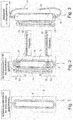
- the Figures 1 and 2 each show a connection area for a dialyzer 1 on a housing 2 of a dialysis machine 3
- Figure 2 the invention with an open disinfection flap (removed connecting bridge) 4
- Figure 1 the invention with a closed disinfection flap (attached connecting bridge) 4.
- a recess in the form of a depression / trough 5 is made in the housing 2 of the dialysis machine 3.
- the recess 5 is concave when viewed from the outside, that is, goes into the planes of the drawing Figures 1 and 2 into it.
- a first connection coupling 6 (hereinafter referred to simply as the first coupling) and a second connection coupling 7 (hereinafter simply referred to as the second coupling) are arranged in the recess 5. They are introduced into elongated holes 8, 9 which are formed on the bottom of the recess 5 and are somewhat recognizable in the figures, and can be clamped to them by screwing them. As a result of their guidance in the elongated holes 8, 9, the two couplings 6, 7 can be positioned relative to one another in direction A.
- the first coupling 5 is fluidically connected to a fresh dialysis liquid supply line not shown in the figures, while the second coupling 6 is connected to a used dialysis liquid discharge line, which is also not shown in the figures.
- FIG. 2 shows the connection area with the disinfection flap 4 open.
- the dialyzer 1 as in FIG Figure 3 is shown, inserted into the connection area.
- Its dialysis fluid connections which protrude radially outward on its circumferential surface 10 and cannot be seen in the figures, are inserted or pushed into the respective corresponding coupling 5, 6.
- the dialyzer 1 with its dialysis fluid connections is held in the couplings 5, 6 and is detachably fixed in position on the housing 2.
- the tubes 11 of the extracorporeal blood circuit there are no tubes in the connection area, so that it is very clear and tidy.
- the disinfection flap 4 is movably fixed on the housing 2 by means of a joint 12 (hinge).
- a joint 12 On its side facing the housing 2 in the closed state, it is provided with sealing plugs 13, 14 which are designed and intended to engage in and seal off the couplings 5, 6.
- the sealing plugs 13, 14 can be designed as hollow pegs and can be connected to one another by a connecting channel not shown in the figures and formed in the disinfection flap. With such a design, the two clutches 5, 6 can be short-circuited by closing the disinfection flap 4, for example for flushing and cleaning purposes.
Landscapes
- Health & Medical Sciences (AREA)
- Heart & Thoracic Surgery (AREA)
- Urology & Nephrology (AREA)
- Vascular Medicine (AREA)
- Hematology (AREA)
- Engineering & Computer Science (AREA)
- Anesthesiology (AREA)
- Biomedical Technology (AREA)
- Life Sciences & Earth Sciences (AREA)
- Animal Behavior & Ethology (AREA)
- General Health & Medical Sciences (AREA)
- Public Health (AREA)
- Veterinary Medicine (AREA)
- Emergency Medicine (AREA)
- Cardiology (AREA)
- External Artificial Organs (AREA)
Description
- Die Erfindung betrifft eine extrakorporale Blutbehandlungsmaschine, insbesondere Dialysemaschine mit einer maschineninternen Fluidik für eine Blutbehandlungsflüssigkeit, vorzugsweise Dialysierflüssigkeit und einem die Fluidik zumindest bereichsweise oder abschnittsweise kapselnden Gehäuse (Maschinengehäuse), wobei die Fluidik eine Zuleitung für frische Blutbehandlungsflüssigkeit (nachfolgend grundsätzlich als Frischdialysierflüssigkeit bezeichnet) zu einem Filter/Dialysator und eine Ableitung für verbrauchte Blutbehandlungsflüssigkeit (nachfolgend grundsätzlich als Brauchdialysierflüssigkeit bezeichnet) vom Filter/Dialysator aufweist, die jeweils endseitig mit einem Anschluss zur lösbaren Kopplung des Filters/Dialysators versehen sind.
- Bei heutigen Dialyseanwendungen werden Dialysemaschinen genutzt, bei denen ein Kartuschen-artiger Filter/Dialysator zunächst mit einer Klemme vorzugsweise außenseitig am Dialysegerät bzw. am Gehäuse der Dialysemaschine befestigt wird. Der so an der Dialysemaschine befestigte Dialysator wird anschließend strömungstechnisch mit der Internfluidik der Dialysemaschine verbunden, indem Schläuche mit Schnellverbindern einerseits mit dafür bestimmten Anschlüssen des Dialysators und andererseits mit dafür bestimmten Anschlüssen der Internfluidik der Dialysemaschine verbunden werden, welche sich ebenfalls am Gehäuse der Dialysemaschine befinden. Diese Dialysierflüssigkeit führenden Schläuche (nachfolgend auch als maschinenseitige Schläuche bezeichnet) liegen neben Blutschläuchen (nachfolgend auch als patientenseitige Schläuche bezeichnet) im Nahbereich des Dialysators vor. Da die Schläuche in der täglichen Praxis in der Regel eher wirr angeordnet sind und/oder sich leicht verwirren können, ist keine besonders hohe Benutzerfreundlichkeit gegeben. Ein weiterer Nachteil bei einer Verwendung von Dialysierflüssigkeitsschläuchen ist, dass es durch die Länge der Schläuche und deren schlechte thermische Isolationseigenschaften in der Regel zu Temperaturverlusten der Dialysierflüssigkeit kommen kann, was dann wieder zu einer Temperaturverringerung des in den patientenseitigen Schläuchen geführten Bluts und damit zu einem Auskühlen des Patienten führen kann. Ein anderer Nachteil ist, dass es in der täglichen Praxis zu Störungen zum Beispiel durch ein Abklemmen oder Abreißen von Schläuchen an Betten, Tischen oder sonstigen Störkonturen kommen kann.
- Zudem ist es bei bekannten Lösungen möglich, dass ungeeignete Filtermodule für die jeweilige Dialysemaschine eingesetzt werden.
- Die Druckschrift
US 2014/0112828 A1 beschreibt eine Dialyseeinheit mit einem Gehäuse, welches eine Dialysatorhalterung in Form von schlüssellochähnlichen Führungen aufweist, in welche an einem Dialysator angebrachte Schnellverschlusskupplungen eingehängt werden können, wobei der Dialysator zu diesem Zeitpunkt jedoch bereits angeschlossen sein muss und somit ein Hantieren mit entsprechenden Schläuchen nicht vermeidbar ist. - Die
US 2014/217029 A1 zeigt einen Fluidkreislauf für eine modular aufgebaute Dialyseeinheit, mit im Gehäuse integrierten Anschlüssen, wobei eine Kassette, welche unter anderem auch den Filter enthält, gegen ein Reinigungselement ausgetauscht werden kann. - Weiterer Stand der Technik findet sich in den Veröffentlichungen
WO 2009/039357 A2 ,WO 01/08722 A2 EP 0 887 100 A1 undDE 36 42 671 A1 . - Ausgehend von dem vorstehend beschriebenen Stand der Technik liegt der vorliegenden Erfindung die Aufgabe zugrunde, die zuvor angeführten Nachteile zu beseitigen, insbesondere eine extrakorporale Blutbehandlungsmaschine, vorzugsweise Dialysemaschine bereit zu stellen, mittels der eine Verbesserung der Anwenderfreundlichkeit bewirkt wird, die besonders übersichtlich ist und eine nutzerseitige Einhandbedienung ermöglicht. Des Weiteren sollen Temperaturverluste der maschinenseitigen Blutbehandlungsflüssigkeit/Dialysierflüssigkeit im Zu-/Ablauf des Filters, d.h. im Dialysatorzu- und -ablauf verringert oder gar vermieden werden.
- Diese Aufgabe wird prinzipiell durch eine extrakorporale Blutbehandlungsmaschine mit den Merkmalen des Patentanspruchs 1 gelöst. Vorteilhafte Weiterbildungen der Erfindung sind Gegenstand der Unteransprüche.
- Insbesondere wird diese Aufgabe gelöst durch eine Blutbehandlungsmaschine/ Dialysemaschine mit einer maschineninternen Fluidik für Blutbehandlungsflüssigkeit/Dialysierflüssigkeit und einem die Fluidik zumindest bereichsweise oder abschnittsweise kapselnden/einschließenden Gehäuse (Maschinengehäuse), wobei die Fluidik eine Zuleitung für Frischdialysierflüssigkeit zu einem Filter/Dialysator und eine Ableitung für Brauchdialysierflüssigkeit vom Filter/Dialysator aufweist, die jeweils endseitig mit einem Anschluss zur lösbaren Kopplung des Filters/Dialysators versehen sind. Erfindungsgemäß ist dieser Anschluss der Zuleitung und/oder dieser Anschluss der Ableitung jeweils als in das Gehäuse (Maschinengehäuse) integrierte Anschluss-Kupplung ausgebildet. D.h. die Anschlüsse der Blutbehandlungsmaschine/Dialysemaschine für den Filter/Dialysator befinden sich erfindungsgemäß nicht mehr an den freien Enden maschinenexterner Verbindungschläuche, sondern sitzen (unmittelbar) auf/in der Außenseite einer Gehäusewand des die Fluidik einschließenden Maschinengehäuses, derart, dass der Filter/Dialysator ohne Zwischenfügen von externen Verbindungsschläuchen (direkt) an die Anschlüsse der Blutbehandlungsmaschine fluidtechnisch und ggf. auch mechanisch angekoppelt werden kann.
- Des Weiteren sind die maschinenseitigen Anschluss-Kupplungen in einer außenseitig im Gehäuse ausgebildeten oder angeordneten konkaven Vertiefung / Mulde / Ausnehmung angeordnet, welche eine Art Aufnahmeschale für den (Kartuschen-artigen) Filter/Dialysator bildet. Die Tiefe einer solchen Vertiefung ist (vorzugsweise leicht/geringfügig) tiefer als die Höhe der Anschluss-Kupplung(en) in dieser Richtung ausgehend vom Vertiefungsgrund, so dass die Anschluss-Kupplung(en) vollständig in die Vertiefung versenkt und geschützt ist/sind. Die Vertiefung ist derart hinsichtlich ihrer Größe und Geometrie ausgebildet, dass sie die Aufnahmeschale/-mulde für den Dialysator ausbildet, deren Dimensionierung/Abmessung an den für die Blutbehandlungsmaschine konkret vorgesehenen Filter/Dialysator angepasst ist. Dadurch kann die Verwendung eines ungeeigneten Filters/Dialysators mit entsprechend unpassenden Abmessungen verhindert werden.
- Vereinfacht kann man sagen, dass die Grundidee, auf der die Erfindung beruht, darin besteht, die Dialysierflüssigkeitsanschlüsse des vorzugsweise Kartuschen-artigen Filters/Dialysators strömungstechnisch mittels gehäuseintegrierter (Gehäusewandintegrierter) Dialysatorkupplungen/Anschluss-Kupplungen der Maschine zur extrakorporalen Blutreinigung zu verbinden, insbesondere unmittelbar (ohne externe Verbindungsschläuche) zu verbinden, sowie eine derart dimensionierte Filteraufnahme bereitzustellen, dass die Verwendung ungeeigneter Filtermodule verhindert wird.
- Nach der Erfindung sind die Anschluss-Kupplungen, mit denen der Filter/Dialysator an die internen Dialysierflüssigkeitsleitungen der Maschine angeschlossen wird, in deren Maschinengehäuse integriert bzw. sitzen unmittelbar an der Außenseite einer Gehäusewand der Maschine. Das bedeutet, dass die Anschluss-Kupplungen in einer für einen Nutzer der Maschine gut zugänglichen Weise mittelbar oder unmittelbar angeordnet, festgelegt oder ausgebildet sein können.
- Die Anschluss-Kupplungen an der Maschine sind vorzugsweise entsprechend der Geometrie und relativen Lage der Dialysierflüssigkeitsanschlüsse des Dialysators zueinander positioniert, derart, dass beide Dialysierflüssigkeitsanschlüsse des Dialysators jeweils gleichzeitig mit der entsprechenden Anschluss-Kupplung der Maschine verbunden, vorzugsweise in diese eingeschoben, aufgesteckt oder aufgeschraubt werden können. Sobald die beiden Dialysierflüssigkeitsanschlüsse des Dialysators in bestimmungsgemäßer Weise in der jeweiligen Anschluss-Kupplung auf Seiten der Maschine sitzen, ist der Dialysierflüssigkeitskreislauf der Maschine geschlossen. Vorzugweise sind die Dialysierflüssigkeitsanschlüsse des Dialysators dann mit einer zum Halten des gesamten Dialysators an der Maschine ausreichenden Kraft gehalten. D.h. die maschinenseitigen Anschluss-Kupplungen sind optional zusätzlich so gestaltet, dass sie für das mechanische Halten des Filters/Dialysators am Maschinengehäuse im normalen Filterbetrieb ausreichend sind und daher die aus dem Stand der Technik bekannten Halteklammern oder Arme ersetzen.
- Nach einer Ausführungsform der Erfindung ist der Dialysator in der Aufnahmemulde durch Reibschluss, Formschluss oder Kraftschluss gehalten. Alternativ oder zusätzlich kann das Gehäuse eine Klemmeinrichtung zum klemmenden Halten des Dialysators aufweisen.
- Außerdem kann es vorgesehen sein, die maschinenseitigen und/oder dialysatorseitigen Anschlüsse nicht fix an der Gehäusewand bzw. Dialysatorkartusche anzuordnen, sondern mit einem Verstellmechanismus oder Adapter zu versehen, um deren Abstände zueinander wahlweise zu verändern. Eine Ausführungsform der Erfindung ist demnach dadurch gekennzeichnet, dass insbesondere die in das Gehäuse integrierten Anschluss-Kupplungen zueinander relativpositionierbar sind. Durch derart zueinander relativpositionierbare Kupplungen kann die Dialysemaschine flexibel mit Dialysatoren unterschiedlicher Größe oder Ausgestaltung genutzt werden. Vorzugsweise sind die Anschluss-Kupplungen zueinander relativpositionierbar und in der entsprechenden Relativposition lagefixierbar. Dazu kann zumindest eine der Anschluss-Kupplungen zum Beispiel mit einem Klemm- oder Schraubmechanismus versehen sein. Bei losem Mechanismus ist dann die zumindest eine Anschluss-Kupplung relativ zum Gehäuse positionierbar. Durch Sperren des Mechanismus ist die zumindest eine Anschluss-Kupplung in der gewünschten Weise zum Gehäuse klemm-/ arretierbar. Eine besonders einfache und nutzerfreundliche Positionierbarkeit der Anschluss-Kupplungen kann bewirkt werden, indem zumindest eine der Anschluss-Kupplungen im Gehäuse in einer Führung, zum Beispiel in einem Langloch, Schlitz oder Nut, verschiebbar aufgenommen ist.
- Nach einer Ausführungsform der Erfindung sind die in das Gehäuse integrierten Anschluss-Kupplungen Schnellkupplungen zum Einschieben von Dialysierflüssigkeitsanschlüssen des Dialysators. Es ist besonders vorteilhaft, wenn diese auf den jeweiligen Dialysierflüssigkeitsanschluss des Dialysators eine zum Festlegen des Dialysators am Gehäuse geeignete, vorbestimmte und definierte Haltekraft ausüben. Dieses kann mittels Reibschluss und/oder Formschluss und/oder Kraftschluss erfolgen, zum Beispiel mittels einer Klemmung, eines Riegelmechanismus oder eines Rastmechanismus, die bei bestimmungsgemäßer Anordnung des Dialysators an der Maschine zur Wirkung kommen.
- Nach einer weiteren Ausführungsform weist die Dialysemaschine des Weiteren ein (einziges/gemeinsames) Deckelelement zum Verschließen, insbesondere zum hermetisch dichten Verschließen, des Klemm-Anschlusses der Zuleitung (Frischdialysierflüssigkeitszuleitung der Dialysemaschine) und (gleichzeitig) des Anschlusses der Ableitung (Brauchdialysierflüssigkeitsableitung der Dialysemaschine) auf. Das (einzige) Deckelelement kann insbesondere einen Fluidkanal aufweisen, über den der Anschluss der Zuleitung mit dem Anschluss der Ableitung verbunden und kurzgeschlossen ist, wenn das Deckelelement die Anschlüsse verschließend am Gehäuse der Blutbehandlungsmaschine angeordnet ist. Ein solches Deckelelement kann besonders einfach als Desinfektionsklappe bei Reinigungs- und Sterilisierungsvorgängen der Internfluidik der Dialysemaschine genutzt werden.
- Eine besonders nutzerfreundliche Ausführungsform kann vorsehen, dass das Deckelelement mittels eines Gelenks oder eines Scharniers bewegbar am maschinenseitigen Gehäuse gehalten ist, so dass es während eines Einsatzes der Maschine (Dialyse) mit an den Anschluss-Kupplungen gehaltenem Dialysator nicht verloren gehen kann.
- Mit der Dialysemaschine nach der Erfindung können in vorteilhafter Weise zahlreiche verschiedene Therapieformen, wie zum Beispiel Hämodialyse (HD), Hämofiltration (HF) oder Hämodiafiltration (HDF) durchgeführt werden.
- Abschließend lässt sich die vorliegende Erfindung zusammenfassend so beschreiben, die Dialysierflüssigkeitsanschlüsse eines Dialysators bzw. an einem Dialysator strömungstechnisch mittels gehäuseintegrierter Dialysator-Anschlusskupplungen einer Maschine zur extrakorporalen Blutreinigung direkt, bzw. ohne Verwendung von externen Verbindungschläuchen zu verbinden. In der Dialysemaschine (-gerät) können die Anschluss-Kupplungen zum Anschluss des Dialysators im Gehäuse integriert ausgebildet sein. Das Gehäuse kann hierfür optional eine Mulde zur räumlichen (Teil-)Aufnahme des Dialysators ausbilden oder eine ebene Fläche darstellen. Zur Desinfektion können die beiden Anschluss-Kupplungen für die Zu-/Abfuhr von Dialysierflüssigikeit zum/vom Dialysator über ein Verbindungselement (Anschlussbrücke) verbunden werden, das vorzugsweise von außerhalb der Maschine einfach auf die beiden Anschluss-Kupplungen aufgesetzt werden kann. Somit ist die Desinfektion der Anschlusskomponenten gewährleistet.
- Wird der Dialysator angeschlossen, ist das Verbindungselement zu entfernen. Dies kann hierfür über ein Gelenk an dem Gehäuse beweglich angelenkt sein. Die Anschluss-Kupplungen sind so ausgeführt, dass eine leichte Verrastung des Dialysators in/an den Anschluss-Kupplungen möglich ist. Um verschiedene Dialysatorgrößen verwenden zu können, kann der Abstand der Anschluss-Kupplungen mit Hilfe eines Verstellmechanismus oder Adapters variabel verändert werden. Zur Entlastung der Anschlussstellen und zur Fixierung des Dialysators kann ein gabel- oder klemmenförmiges Führungselement zur Gewichtskraftaufnahme des Dialysators in den Aufbau integriert sein. Zum Entfernen des Dialysators kann eine zentrale Entkupplungsvorrichtung bzw. Auswerffunktion integriert sein.
- Durch die Erfindung können insbesondere die folgenden Vorteile bewirkt werden:
- Es führen keine freiliegenden Schläuche vom Gerät zum Dialysator.
- Infolgedessen ist der Temperaturverlust der Dialysierflüssigkeit zwischen dem Dialysator und den endseitigen Kupplungen der Dialysierflüssigkeitsleitungen gering oder sogar nicht vorhanden, anders als bei in bekannter Weise durch Schläuche an die Dialysemaschine angeschlossenen Dialysatoren.
- Der Dialysatorbereich ist deutlich aufgeräumter, insbesondere kann es nicht zu einem Verwirren von Dialysierflüssigkeitsschläuchen mit den Blutschläuchen kommen.
- Es können keine Schläuche an oder durch nebenstehende Betten abgerissen/abgeklemmt werden.
- Die Anwenderfreundlichkeit ist durch die mittels der Erfindung bewirkte klare, aufgeräumte Anordnung und Optik gesteigert.
- In besonders vorteilhafter Weise ist eine Einhandbedienung, also ein Anschließen und/oder Abnehmen eines Dialysators an der Dialysemaschine möglich.
- Rüstzeiten sind gegenüber dem Stand der Technik deutlich verkürzt.
- Die Erfindung wird im Folgenden anhand beispielhafter, nicht einschränkender und in den angehängten Figuren gezeigter Ausführungsformen näher erläutert. Dabei zeigt:
-
Figur 1 eine schematische Aufsicht auf einen Anschlussbereich für einen Dialysator an einem Gehäuse einer Dialysemaschine nach der Erfindung mit geschlossener Desinfektionsklappe, -
Figur 2 eine schematische Aufsicht gemäßFigur 1 mit geöffneter Desinfektionsklappe und -
Figur 3 eine schematische Aufsicht gemäßFigur 2 mit einem mit der Internfluidik der Dialysemaschine verbundenen und am Gehäuse gehaltenen Dialysator. - Die
Figuren 1 und 2 zeigen jeweils einen Anschlussbereich für einen Dialysator 1 an einem Gehäuse 2 einer Dialysemaschine 3. Dabei verdeutlichtFigur 2 die Erfindung mit offener Desinfektionsklappe (abgenommener Verbindungsbrücke) 4 undFigur 1 die Erfindung mit geschlossener Desinfektionsklappe (aufgesetzter Verbindungsbrücke) 4. In das Gehäuse 2 der Dialysemaschine 3 ist eine Ausnehmung in Form einer Vertiefung/ Mulde 5 eingebracht. Die Vertiefung 5 ist von außen betrachtet konkav, das heißt geht in die Zeichnungsebenen derFiguren 1 und 2 hinein. - In der Vertiefung 5 sind eine erste Anschluss-Kupplung 6 (nachfolgend einfach als erste Kupplung bezeichnet) und eine zweite Anschluss-Kupplung 7 (nachfolgend einfach als zweite Kupplung bezeichnet) angeordnet. Sie sind in auf dem Boden der Vertiefung 5 ausgebildeten und in den Figuren etwas erkennbaren Langlöchern 8, 9 eingebracht und können durch Verschrauben mit diesen verklemmt werden. Infolge ihrer Führung in den Langlöchern 8, 9 sind die beiden Kupplungen 6, 7 zueinander in Richtung A relativpositionierbar. Die erste Kupplung 5 ist strömungstechnisch mit einer in den Figuren nicht dargestellten Frischdialysierflüssigkeitszuleitung verbunden, während die zweite Kupplung 6 mit einer in den Figuren ebenfalls nicht dargestellten Brauchdialysierflüssigkeitsableitung verbunden ist.
-
Figur 2 zeigt den Anschlussbereich bei geöffneter Desinfektionsklappe 4. In diesem Zustand wird der Dialysator 1, wie inFigur 3 dargestellt ist, in den Anschlussbereich eingesetzt. Dabei werden dessen an seiner Umfangsfläche 10 radial nach außen ragende Dialysierflüssigkeitsanschlüsse, die in den Figuren nicht erkennbar sind, in die jeweils entsprechende Kupplung 5, 6 eingesetzt oder eingeschoben. Bei Erreichen der bestimmungsgemäßen Endlage des Dialysators 1 am Gehäuse 2 sind die Dialysierflüssigkeitsseite des Dialysators 1, die Frischdialysierflüssigkeitszuleitung und die Brauchdialysierflüssigkeitsableitung strömungstechnisch miteinander verbunden. Des Weiteren ist der Dialysator 1 mit seinen Dialysierflüssigkeitsanschlüssen in den Kupplungen 5, 6 gehalten und am Gehäuse 2 abnehmbar lagefixiert. Bis auf Schläuche 11 des extrakorporalen Blutkreislaufs sind keine Schläuche im Anschlussbereich vorhanden, so dass dieser sehr übersichtlich und aufgeräumt ist. - Die Desinfektionsklappe 4 ist mittels eines Gelenks 12 (Scharnier) am Gehäuse 2 beweglich festgelegt. An ihrer im geschlossenen Zustand dem Gehäuse 2 zugewandten Seite ist sie mit Verschlussstopfen 13, 14 versehen, die zum Eingreifen in und Abdichten der Kupplungen 5, 6 ausgebildet und bestimmt sind. Die Verschlussstopfen 13, 14 können nach einer Form der Erfindung als Hohlzapfen ausgebildet sein und mit einem in den Figuren nicht dargestellten und in der Desinfektionsklappe ausgebildeten Verbindungskanal miteinander verbunden sein. Bei einer solchen Ausbildung können die beiden Kupplungen 5, 6 durch Schließen der Desinfektionsklappe 4 kurzgeschlossen werden, zum Beispiel zu Spülungs- und Reinigungszwecken.
-
- 1 Dialysator
- 2 Gehäuse
- 3 Dialysemaschine
- 4 Desinfektionsklappe
- 5 Vertiefung
- 6 Kupplung
- 7 Kupplung
- 8 Langloch
- 9 Langloch
- 10 Umfangsfläche
- 11 Schlauch extrakorporaler Blutkreislauf
- 12 Gelenk, Scharnier
- 13 Verschlussstopfen
- 14 Verschlussstopfen
Claims (8)
- Extrakorporale Blutbehandlungsmaschine, vorzugsweise Dialysemaschine (3) mit einer maschineninternen Fluidik für eine Blutbehandlungsflüssigkeit und einem die Fluidik zumindest bereichsweise umgebenden Maschinengehäuse (2), wobei die Fluidik eine Zuleitung für frische Blutbehandlungsflüssigkeit zu einem Filter, vorzugsweise Dialysator (1) und eine Ableitung für verbrauchte Blutbehandlungsflüssigkeit vom Filter (1) aufweist, die jeweils endseitig mit einem Anschluss zur lösbaren Kopplung des Filters (1) an der maschineninternen Fluidik versehen sind, wobei der Anschluss der Zuleitung und der Anschluss der Ableitung jeweils als in das Maschinengehäuse (2) integrierte Anschluss-Kupplung (6, 7) ausgebildet sind und die Anschluss-Kupplungen (6, 7) in einer außenseitig im Maschinengehäuse (2) ausgebildeten oder angeordneten konkaven Ausnehmung (5) angeordnet sind, dadurch gekennzeichnet, dass die Ausnehmung (5) hinsichtlich ihrer Größe und Geometrie derart ausgebildet ist, dass sie eine Aufnahmemulde für den Filter (1) ausbildet, deren Abmessungen an den für die Blutbehandlungsmaschine (3) konkret vorgesehenen Filter (1) angepasst sind, derart, dass die Verwendung eines ungeeigneten Filters mit entsprechend unpassenden Abmessungen verhinderbar ist.
- Extrakorporale Blutbehandlungsmaschine (3) nach Anspruch 1, dadurch gekennzeichnet, dass der Filter (1) in der Aufnahmemulde durch einen mit der Aufnahmemulde eingehenden Reibschluss, Formschluss oder Kraftschluss gehalten ist.
- Extrakorporale Blutbehandlungsmaschine (3) nach einem der vorstehenden Ansprüche, dadurch gekennzeichnet, dass das Maschinengehäuse (2) eine Klemmeinrichtung zum klemmenden Halten des Filters (1) aufweist.
- Extrakorporale Blutbehandlungsmaschine (3) nach einem der vorstehenden Ansprüche, dadurch gekennzeichnet, dass die in das Maschinengehäuse (2) integrierten Anschluss-Kupplungen (6, 7) zueinander relativpositionierbar sind, insbesondere zumindest eine der Kupplungen (6, 7) im Maschinengehäuse (2) in einer Führung (8, 9) verschiebbar aufgenommen ist.
- Extrakorporale Blutbehandlungsmaschine (3) nach einem der vorstehenden Ansprüche, dadurch gekennzeichnet, dass die in das Maschinengehäuse (2) integrierten Anschluss-Kupplungen (6, 7) Schnellkupplungen zum Einschieben von Dialysierflüssigkeitsanschlüssen des Filters (1) sind, die auf den jeweiligen Dialysierflüssigkeitsanschluss eine zum Festlegen des Filters (1) am Maschinengehäuse (2) geeignete, vorbestimmte und definierte Haltekraft ausüben.
- Extrakorporale Blutbehandlungsmaschine (3) nach einem der vorstehenden Ansprüche, dadurch gekennzeichnet, dass diese des Weiteren ein Deckelelement (4) zum Verschließen der Anschluss-Kupplung der Zuleitung und der Anschluss-Kupplung der Ableitung aufweist.
- Extrakorporale Blutbehandlungsmaschine (3) nach Anspruch 6, dadurch gekennzeichnet, dass das Deckelelement (4) einen Fluidkanal aufweist, über den die Anschluss-Kupplung der Zuleitung (6) mit der Anschluss-Kupplung der Ableitung (7) verbunden und kurzgeschlossen ist, wenn das Deckelelement (4) die Anschluss-Kupplungen verschließend am Maschinengehäuse (2) angeordnet ist.
- Extrakorporale Blutbehandlungsmaschine (3) nach Anspruch 6 oder 7,
dadurch gekennzeichnet, dass das Deckelelement (4) mittels eines Gelenks 12) oder eines Scharniers bewegbar am Maschinengehäuse (2) gehalten ist.
Applications Claiming Priority (1)
| Application Number | Priority Date | Filing Date | Title |
|---|---|---|---|
| DE102015120218.2A DE102015120218A1 (de) | 2015-11-23 | 2015-11-23 | Dialysemaschine mit integrierter Dialysatorkupplung |
Publications (2)
| Publication Number | Publication Date |
|---|---|
| EP3170518A1 EP3170518A1 (de) | 2017-05-24 |
| EP3170518B1 true EP3170518B1 (de) | 2021-07-28 |
Family
ID=57241005
Family Applications (1)
| Application Number | Title | Priority Date | Filing Date |
|---|---|---|---|
| EP16197524.8A Active EP3170518B1 (de) | 2015-11-23 | 2016-11-07 | Dialysemaschine mit integrierter dialysatorkupplung |
Country Status (5)
| Country | Link |
|---|---|
| US (1) | US10172990B2 (de) |
| EP (1) | EP3170518B1 (de) |
| JP (1) | JP2017131625A (de) |
| CN (2) | CN106823030B (de) |
| DE (1) | DE102015120218A1 (de) |
Families Citing this family (6)
| Publication number | Priority date | Publication date | Assignee | Title |
|---|---|---|---|---|
| DE102015120218A1 (de) * | 2015-11-23 | 2017-05-24 | B. Braun Avitum Ag | Dialysemaschine mit integrierter Dialysatorkupplung |
| EP3991764B1 (de) | 2020-10-27 | 2024-03-06 | Bellco S.r.l. | Durchflussmesser zum dosieren von wasser in einem dialysesystem |
| US12318528B2 (en) | 2020-10-30 | 2025-06-03 | Mozarc Medical Us Llc | Variable orifice fistula graft |
| EP3991770B1 (de) | 2020-10-30 | 2024-10-30 | Bellco S.r.l. | Dialysekassette mit pumpfunktionen |
| EP4008376A1 (de) | 2020-12-03 | 2022-06-08 | Medtronic, Inc. | Flexibles rohr-routing-zubehör für peritoneal dialysis system |
| DE102022101299A1 (de) | 2022-01-20 | 2023-07-20 | B.Braun Avitum Ag | Extrakorporale Blutbehandlungsmaschine mit Betätigungsvorrichtung |
Family Cites Families (13)
| Publication number | Priority date | Publication date | Assignee | Title |
|---|---|---|---|---|
| DE8633407U1 (de) * | 1986-12-13 | 1989-09-21 | Saueressig, Ulrich, Dr.med., 5600 Wuppertal | Haltestück für einen Dialysator für die Hämodialyse |
| NL8701233A (nl) * | 1987-05-22 | 1988-12-16 | Medistad Holland | Bloedverwarmingstoestel. |
| DE19727251C2 (de) * | 1997-06-26 | 2002-06-06 | Fresenius Medical Care De Gmbh | Filtervorrichtung und Vorrichtung zu deren Halterung |
| DE19852982C1 (de) * | 1998-11-17 | 2000-03-16 | Braun Melsungen Ag | Kartuschenhalter für eine Dialysemaschine |
| ITTO990148U1 (it) * | 1999-07-30 | 2001-01-30 | Hospal Dasco Spa | Unita' di filtrazione per una macchina di dialisi. |
| US8038639B2 (en) * | 2004-11-04 | 2011-10-18 | Baxter International Inc. | Medical fluid system with flexible sheeting disposable unit |
| CN102784422B (zh) * | 2007-09-19 | 2015-05-06 | 弗雷塞尼斯医疗保健控股公司 | 透析系统及相关部件 |
| CA3177048A1 (en) * | 2007-10-12 | 2009-04-23 | Deka Products Limited Partnership | Apparatus and methods for hemodialysis |
| CN202122732U (zh) * | 2010-03-25 | 2012-01-25 | 彭罗民 | 节水型人工肾 |
| SG10201809897VA (en) * | 2011-05-24 | 2018-12-28 | Deka Products Lp | Hemodialysis System |
| DE102012105917A1 (de) * | 2012-07-03 | 2014-01-09 | B. Braun Avitum Ag | Multikonnektor und medizinisches Gerät zur extrakorporalen Blutbehandlung |
| US10010663B2 (en) * | 2013-02-01 | 2018-07-03 | Medtronic, Inc. | Fluid circuit for delivery of renal replacement therapies |
| DE102015120218A1 (de) * | 2015-11-23 | 2017-05-24 | B. Braun Avitum Ag | Dialysemaschine mit integrierter Dialysatorkupplung |
-
2015
- 2015-11-23 DE DE102015120218.2A patent/DE102015120218A1/de not_active Withdrawn
-
2016
- 2016-10-27 JP JP2016210571A patent/JP2017131625A/ja active Pending
- 2016-11-07 EP EP16197524.8A patent/EP3170518B1/de active Active
- 2016-11-08 US US15/346,091 patent/US10172990B2/en active Active
- 2016-11-17 CN CN201611022740.0A patent/CN106823030B/zh active Active
- 2016-11-17 CN CN201621234217.XU patent/CN207253526U/zh active Active
Non-Patent Citations (1)
| Title |
|---|
| None * |
Also Published As
| Publication number | Publication date |
|---|---|
| CN106823030A (zh) | 2017-06-13 |
| JP2017131625A (ja) | 2017-08-03 |
| US10172990B2 (en) | 2019-01-08 |
| CN207253526U (zh) | 2018-04-20 |
| DE102015120218A1 (de) | 2017-05-24 |
| EP3170518A1 (de) | 2017-05-24 |
| CN106823030B (zh) | 2021-04-13 |
| US20170143885A1 (en) | 2017-05-25 |
Similar Documents
| Publication | Publication Date | Title |
|---|---|---|
| EP3170518B1 (de) | Dialysemaschine mit integrierter dialysatorkupplung | |
| EP2146774B2 (de) | Drainageschlaucheinheit | |
| DE19925297C1 (de) | Kartuschenhalter für eine Dialysemaschine | |
| EP2288395B1 (de) | Organizer zum lösbaren aufnehmen von komponenten von blutschlauchsätzen und verfahren zum herstellen sowie zum vorbereiten desselben | |
| EP1684847B1 (de) | Konnektor für dialyseport | |
| EP3061489B1 (de) | Konnektor für einen dialysator | |
| DE19727251A1 (de) | Filtervorrichtung und Vorrichtung zu deren Halterung | |
| DE69625279T2 (de) | Kombinierter Halter und Anschluss für einen Dialysator | |
| EP2671611B1 (de) | Verbinder und medizinisches Gerät zur extrakorporalen Blutbehandlung mit einem solchen Verbinder | |
| WO2010121821A1 (de) | Haltevorrichtung zum halten einer externen funktionseinrichtung an einer behandlungsvorrichtung, externe funktionseinrichtung sowie behandlungsvorrichtung | |
| DE102013019382A1 (de) | Reinigungsvorrichtung und Reinigungsverfahren | |
| EP2682606A1 (de) | Multikonnektor und medizinisches Gerät zur extrakorporalen Blutbehandlung | |
| EP4429729A1 (de) | Dialysegerät mit konnektionseinheit | |
| EP3668637A1 (de) | Anschlussvorrichtung für ein rohrförmiges filtermodul | |
| DE102019123806A1 (de) | Medizinischer Konnektor mit automatischer Abdichtung bei der Dekonnektion | |
| EP3758769B1 (de) | Halteeinrichtung zum halten eines oxygenators und einer blutpumpe | |
| DE102010049684A1 (de) | Spülvorrichtung und Spülverfahren | |
| EP1727574B1 (de) | Vorrichtung zum wechseln und/oder andocken von funktionsmodulen | |
| EP3600494B1 (de) | Haltevorrichtung für medizinische behandlungsvorrichtungen | |
| WO2017186695A1 (de) | Entnahmeport zum entnehmen einer flüssigkeit, system und verwendung eines entnahmeports | |
| DE102016115269B4 (de) | Dialysatorhalter | |
| DE102012109343B4 (de) | Vorrichtung zum Anschließen von Schläuchen an medizinische Geräte | |
| DE102009024448A1 (de) | Haltevorrichtung zum Halten einer externen Funktionseinrichtung an einer Behandlungsvorrichtung, externe Funktionseinrichtung sowie Behandlungsvorrichtung | |
| EP3941548B1 (de) | Extrakorporale blutbehandlungsmaschine mit poka yoke für druckaufnehmer | |
| DE102020133686A1 (de) | Konnektor für Dialysatorport, Dialysator, Verfahren und Blutbehandlungsvorrichtung |
Legal Events
| Date | Code | Title | Description |
|---|---|---|---|
| PUAI | Public reference made under article 153(3) epc to a published international application that has entered the european phase |
Free format text: ORIGINAL CODE: 0009012 |
|
| STAA | Information on the status of an ep patent application or granted ep patent |
Free format text: STATUS: THE APPLICATION HAS BEEN PUBLISHED |
|
| AK | Designated contracting states |
Kind code of ref document: A1 Designated state(s): AL AT BE BG CH CY CZ DE DK EE ES FI FR GB GR HR HU IE IS IT LI LT LU LV MC MK MT NL NO PL PT RO RS SE SI SK SM TR |
|
| AX | Request for extension of the european patent |
Extension state: BA ME |
|
| STAA | Information on the status of an ep patent application or granted ep patent |
Free format text: STATUS: REQUEST FOR EXAMINATION WAS MADE |
|
| 17P | Request for examination filed |
Effective date: 20170802 |
|
| STAA | Information on the status of an ep patent application or granted ep patent |
Free format text: STATUS: EXAMINATION IS IN PROGRESS |
|
| 17Q | First examination report despatched |
Effective date: 20180417 |
|
| GRAP | Despatch of communication of intention to grant a patent |
Free format text: ORIGINAL CODE: EPIDOSNIGR1 |
|
| STAA | Information on the status of an ep patent application or granted ep patent |
Free format text: STATUS: GRANT OF PATENT IS INTENDED |
|
| INTG | Intention to grant announced |
Effective date: 20210208 |
|
| GRAS | Grant fee paid |
Free format text: ORIGINAL CODE: EPIDOSNIGR3 |
|
| GRAA | (expected) grant |
Free format text: ORIGINAL CODE: 0009210 |
|
| STAA | Information on the status of an ep patent application or granted ep patent |
Free format text: STATUS: THE PATENT HAS BEEN GRANTED |
|
| AK | Designated contracting states |
Kind code of ref document: B1 Designated state(s): AL AT BE BG CH CY CZ DE DK EE ES FI FR GB GR HR HU IE IS IT LI LT LU LV MC MK MT NL NO PL PT RO RS SE SI SK SM TR |
|
| REG | Reference to a national code |
Ref country code: GB Ref legal event code: FG4D Free format text: NOT ENGLISH |
|
| REG | Reference to a national code |
Ref country code: CH Ref legal event code: EP |
|
| REG | Reference to a national code |
Ref country code: AT Ref legal event code: REF Ref document number: 1414124 Country of ref document: AT Kind code of ref document: T Effective date: 20210815 |
|
| REG | Reference to a national code |
Ref country code: IE Ref legal event code: FG4D Free format text: LANGUAGE OF EP DOCUMENT: GERMAN |
|
| REG | Reference to a national code |
Ref country code: DE Ref legal event code: R096 Ref document number: 502016013480 Country of ref document: DE |
|
| REG | Reference to a national code |
Ref country code: SE Ref legal event code: TRGR |
|
| REG | Reference to a national code |
Ref country code: LT Ref legal event code: MG9D |
|
| REG | Reference to a national code |
Ref country code: NL Ref legal event code: MP Effective date: 20210728 |
|
| PG25 | Lapsed in a contracting state [announced via postgrant information from national office to epo] |
Ref country code: LT Free format text: LAPSE BECAUSE OF FAILURE TO SUBMIT A TRANSLATION OF THE DESCRIPTION OR TO PAY THE FEE WITHIN THE PRESCRIBED TIME-LIMIT Effective date: 20210728 Ref country code: BG Free format text: LAPSE BECAUSE OF FAILURE TO SUBMIT A TRANSLATION OF THE DESCRIPTION OR TO PAY THE FEE WITHIN THE PRESCRIBED TIME-LIMIT Effective date: 20211028 Ref country code: NO Free format text: LAPSE BECAUSE OF FAILURE TO SUBMIT A TRANSLATION OF THE DESCRIPTION OR TO PAY THE FEE WITHIN THE PRESCRIBED TIME-LIMIT Effective date: 20211028 Ref country code: NL Free format text: LAPSE BECAUSE OF FAILURE TO SUBMIT A TRANSLATION OF THE DESCRIPTION OR TO PAY THE FEE WITHIN THE PRESCRIBED TIME-LIMIT Effective date: 20210728 Ref country code: PT Free format text: LAPSE BECAUSE OF FAILURE TO SUBMIT A TRANSLATION OF THE DESCRIPTION OR TO PAY THE FEE WITHIN THE PRESCRIBED TIME-LIMIT Effective date: 20211129 Ref country code: ES Free format text: LAPSE BECAUSE OF FAILURE TO SUBMIT A TRANSLATION OF THE DESCRIPTION OR TO PAY THE FEE WITHIN THE PRESCRIBED TIME-LIMIT Effective date: 20210728 Ref country code: FI Free format text: LAPSE BECAUSE OF FAILURE TO SUBMIT A TRANSLATION OF THE DESCRIPTION OR TO PAY THE FEE WITHIN THE PRESCRIBED TIME-LIMIT Effective date: 20210728 Ref country code: HR Free format text: LAPSE BECAUSE OF FAILURE TO SUBMIT A TRANSLATION OF THE DESCRIPTION OR TO PAY THE FEE WITHIN THE PRESCRIBED TIME-LIMIT Effective date: 20210728 Ref country code: RS Free format text: LAPSE BECAUSE OF FAILURE TO SUBMIT A TRANSLATION OF THE DESCRIPTION OR TO PAY THE FEE WITHIN THE PRESCRIBED TIME-LIMIT Effective date: 20210728 |
|
| PG25 | Lapsed in a contracting state [announced via postgrant information from national office to epo] |
Ref country code: PL Free format text: LAPSE BECAUSE OF FAILURE TO SUBMIT A TRANSLATION OF THE DESCRIPTION OR TO PAY THE FEE WITHIN THE PRESCRIBED TIME-LIMIT Effective date: 20210728 Ref country code: LV Free format text: LAPSE BECAUSE OF FAILURE TO SUBMIT A TRANSLATION OF THE DESCRIPTION OR TO PAY THE FEE WITHIN THE PRESCRIBED TIME-LIMIT Effective date: 20210728 Ref country code: GR Free format text: LAPSE BECAUSE OF FAILURE TO SUBMIT A TRANSLATION OF THE DESCRIPTION OR TO PAY THE FEE WITHIN THE PRESCRIBED TIME-LIMIT Effective date: 20211029 |
|
| PG25 | Lapsed in a contracting state [announced via postgrant information from national office to epo] |
Ref country code: DK Free format text: LAPSE BECAUSE OF FAILURE TO SUBMIT A TRANSLATION OF THE DESCRIPTION OR TO PAY THE FEE WITHIN THE PRESCRIBED TIME-LIMIT Effective date: 20210728 |
|
| REG | Reference to a national code |
Ref country code: DE Ref legal event code: R097 Ref document number: 502016013480 Country of ref document: DE |
|
| PG25 | Lapsed in a contracting state [announced via postgrant information from national office to epo] |
Ref country code: SM Free format text: LAPSE BECAUSE OF FAILURE TO SUBMIT A TRANSLATION OF THE DESCRIPTION OR TO PAY THE FEE WITHIN THE PRESCRIBED TIME-LIMIT Effective date: 20210728 Ref country code: SK Free format text: LAPSE BECAUSE OF FAILURE TO SUBMIT A TRANSLATION OF THE DESCRIPTION OR TO PAY THE FEE WITHIN THE PRESCRIBED TIME-LIMIT Effective date: 20210728 Ref country code: RO Free format text: LAPSE BECAUSE OF FAILURE TO SUBMIT A TRANSLATION OF THE DESCRIPTION OR TO PAY THE FEE WITHIN THE PRESCRIBED TIME-LIMIT Effective date: 20210728 Ref country code: EE Free format text: LAPSE BECAUSE OF FAILURE TO SUBMIT A TRANSLATION OF THE DESCRIPTION OR TO PAY THE FEE WITHIN THE PRESCRIBED TIME-LIMIT Effective date: 20210728 Ref country code: CZ Free format text: LAPSE BECAUSE OF FAILURE TO SUBMIT A TRANSLATION OF THE DESCRIPTION OR TO PAY THE FEE WITHIN THE PRESCRIBED TIME-LIMIT Effective date: 20210728 Ref country code: AL Free format text: LAPSE BECAUSE OF FAILURE TO SUBMIT A TRANSLATION OF THE DESCRIPTION OR TO PAY THE FEE WITHIN THE PRESCRIBED TIME-LIMIT Effective date: 20210728 |
|
| PLBE | No opposition filed within time limit |
Free format text: ORIGINAL CODE: 0009261 |
|
| STAA | Information on the status of an ep patent application or granted ep patent |
Free format text: STATUS: NO OPPOSITION FILED WITHIN TIME LIMIT |
|
| PG25 | Lapsed in a contracting state [announced via postgrant information from national office to epo] |
Ref country code: MC Free format text: LAPSE BECAUSE OF FAILURE TO SUBMIT A TRANSLATION OF THE DESCRIPTION OR TO PAY THE FEE WITHIN THE PRESCRIBED TIME-LIMIT Effective date: 20210728 |
|
| REG | Reference to a national code |
Ref country code: CH Ref legal event code: PL |
|
| 26N | No opposition filed |
Effective date: 20220429 |
|
| GBPC | Gb: european patent ceased through non-payment of renewal fee |
Effective date: 20211107 |
|
| PG25 | Lapsed in a contracting state [announced via postgrant information from national office to epo] |
Ref country code: LU Free format text: LAPSE BECAUSE OF NON-PAYMENT OF DUE FEES Effective date: 20211107 Ref country code: BE Free format text: LAPSE BECAUSE OF NON-PAYMENT OF DUE FEES Effective date: 20211130 |
|
| REG | Reference to a national code |
Ref country code: BE Ref legal event code: MM Effective date: 20211130 |
|
| PG25 | Lapsed in a contracting state [announced via postgrant information from national office to epo] |
Ref country code: LI Free format text: LAPSE BECAUSE OF NON-PAYMENT OF DUE FEES Effective date: 20211130 Ref country code: CH Free format text: LAPSE BECAUSE OF NON-PAYMENT OF DUE FEES Effective date: 20211130 |
|
| PG25 | Lapsed in a contracting state [announced via postgrant information from national office to epo] |
Ref country code: IE Free format text: LAPSE BECAUSE OF NON-PAYMENT OF DUE FEES Effective date: 20211107 Ref country code: GB Free format text: LAPSE BECAUSE OF NON-PAYMENT OF DUE FEES Effective date: 20211107 |
|
| PG25 | Lapsed in a contracting state [announced via postgrant information from national office to epo] |
Ref country code: FR Free format text: LAPSE BECAUSE OF NON-PAYMENT OF DUE FEES Effective date: 20211130 |
|
| REG | Reference to a national code |
Ref country code: AT Ref legal event code: MM01 Ref document number: 1414124 Country of ref document: AT Kind code of ref document: T Effective date: 20211107 |
|
| PG25 | Lapsed in a contracting state [announced via postgrant information from national office to epo] |
Ref country code: AT Free format text: LAPSE BECAUSE OF NON-PAYMENT OF DUE FEES Effective date: 20211107 |
|
| PG25 | Lapsed in a contracting state [announced via postgrant information from national office to epo] |
Ref country code: HU Free format text: LAPSE BECAUSE OF FAILURE TO SUBMIT A TRANSLATION OF THE DESCRIPTION OR TO PAY THE FEE WITHIN THE PRESCRIBED TIME-LIMIT; INVALID AB INITIO Effective date: 20161107 |
|
| PG25 | Lapsed in a contracting state [announced via postgrant information from national office to epo] |
Ref country code: CY Free format text: LAPSE BECAUSE OF FAILURE TO SUBMIT A TRANSLATION OF THE DESCRIPTION OR TO PAY THE FEE WITHIN THE PRESCRIBED TIME-LIMIT Effective date: 20210728 |
|
| P01 | Opt-out of the competence of the unified patent court (upc) registered |
Effective date: 20231010 |
|
| PG25 | Lapsed in a contracting state [announced via postgrant information from national office to epo] |
Ref country code: MK Free format text: LAPSE BECAUSE OF FAILURE TO SUBMIT A TRANSLATION OF THE DESCRIPTION OR TO PAY THE FEE WITHIN THE PRESCRIBED TIME-LIMIT Effective date: 20210728 |
|
| PG25 | Lapsed in a contracting state [announced via postgrant information from national office to epo] |
Ref country code: MT Free format text: LAPSE BECAUSE OF FAILURE TO SUBMIT A TRANSLATION OF THE DESCRIPTION OR TO PAY THE FEE WITHIN THE PRESCRIBED TIME-LIMIT Effective date: 20210728 |
|
| PG25 | Lapsed in a contracting state [announced via postgrant information from national office to epo] |
Ref country code: TR Free format text: LAPSE BECAUSE OF FAILURE TO SUBMIT A TRANSLATION OF THE DESCRIPTION OR TO PAY THE FEE WITHIN THE PRESCRIBED TIME-LIMIT Effective date: 20210728 |
|
| PGFP | Annual fee paid to national office [announced via postgrant information from national office to epo] |
Ref country code: DE Payment date: 20251118 Year of fee payment: 10 |
|
| PGFP | Annual fee paid to national office [announced via postgrant information from national office to epo] |
Ref country code: IT Payment date: 20251128 Year of fee payment: 10 |
|
| PGFP | Annual fee paid to national office [announced via postgrant information from national office to epo] |
Ref country code: SE Payment date: 20251119 Year of fee payment: 10 |