EP3170646A2 - Procédé de fabrication d'une chemise destinée à revêtir des conduites et dispositif d'exécution du procédé - Google Patents
Procédé de fabrication d'une chemise destinée à revêtir des conduites et dispositif d'exécution du procédé Download PDFInfo
- Publication number
- EP3170646A2 EP3170646A2 EP16002160.6A EP16002160A EP3170646A2 EP 3170646 A2 EP3170646 A2 EP 3170646A2 EP 16002160 A EP16002160 A EP 16002160A EP 3170646 A2 EP3170646 A2 EP 3170646A2
- Authority
- EP
- European Patent Office
- Prior art keywords
- inner film
- film tube
- winding mandrel
- guide
- lining
- Prior art date
- Legal status (The legal status is an assumption and is not a legal conclusion. Google has not performed a legal analysis and makes no representation as to the accuracy of the status listed.)
- Granted
Links
Images


Classifications
-
- B—PERFORMING OPERATIONS; TRANSPORTING
- B29—WORKING OF PLASTICS; WORKING OF SUBSTANCES IN A PLASTIC STATE IN GENERAL
- B29C—SHAPING OR JOINING OF PLASTICS; SHAPING OF MATERIAL IN A PLASTIC STATE, NOT OTHERWISE PROVIDED FOR; AFTER-TREATMENT OF THE SHAPED PRODUCTS, e.g. REPAIRING
- B29C63/00—Lining or sheathing, i.e. applying preformed layers or sheathings of plastics; Apparatus therefor
- B29C63/48—Preparation of the surfaces
- B29C63/481—Preparation of the surfaces mechanically
-
- B—PERFORMING OPERATIONS; TRANSPORTING
- B29—WORKING OF PLASTICS; WORKING OF SUBSTANCES IN A PLASTIC STATE IN GENERAL
- B29C—SHAPING OR JOINING OF PLASTICS; SHAPING OF MATERIAL IN A PLASTIC STATE, NOT OTHERWISE PROVIDED FOR; AFTER-TREATMENT OF THE SHAPED PRODUCTS, e.g. REPAIRING
- B29C63/00—Lining or sheathing, i.e. applying preformed layers or sheathings of plastics; Apparatus therefor
- B29C63/0004—Component parts, details or accessories; Auxiliary operations
-
- B—PERFORMING OPERATIONS; TRANSPORTING
- B29—WORKING OF PLASTICS; WORKING OF SUBSTANCES IN A PLASTIC STATE IN GENERAL
- B29C—SHAPING OR JOINING OF PLASTICS; SHAPING OF MATERIAL IN A PLASTIC STATE, NOT OTHERWISE PROVIDED FOR; AFTER-TREATMENT OF THE SHAPED PRODUCTS, e.g. REPAIRING
- B29C63/00—Lining or sheathing, i.e. applying preformed layers or sheathings of plastics; Apparatus therefor
- B29C63/02—Lining or sheathing, i.e. applying preformed layers or sheathings of plastics; Apparatus therefor using sheet or web-like material
- B29C63/024—Lining or sheathing, i.e. applying preformed layers or sheathings of plastics; Apparatus therefor using sheet or web-like material the sheet or web-like material being supported by a moving carriage
-
- B—PERFORMING OPERATIONS; TRANSPORTING
- B29—WORKING OF PLASTICS; WORKING OF SUBSTANCES IN A PLASTIC STATE IN GENERAL
- B29C—SHAPING OR JOINING OF PLASTICS; SHAPING OF MATERIAL IN A PLASTIC STATE, NOT OTHERWISE PROVIDED FOR; AFTER-TREATMENT OF THE SHAPED PRODUCTS, e.g. REPAIRING
- B29C63/00—Lining or sheathing, i.e. applying preformed layers or sheathings of plastics; Apparatus therefor
- B29C63/02—Lining or sheathing, i.e. applying preformed layers or sheathings of plastics; Apparatus therefor using sheet or web-like material
- B29C63/04—Lining or sheathing, i.e. applying preformed layers or sheathings of plastics; Apparatus therefor using sheet or web-like material by folding, winding, bending or the like
- B29C63/06—Lining or sheathing, i.e. applying preformed layers or sheathings of plastics; Apparatus therefor using sheet or web-like material by folding, winding, bending or the like around tubular articles
- B29C63/065—Lining or sheathing, i.e. applying preformed layers or sheathings of plastics; Apparatus therefor using sheet or web-like material by folding, winding, bending or the like around tubular articles continuously
-
- B—PERFORMING OPERATIONS; TRANSPORTING
- B29—WORKING OF PLASTICS; WORKING OF SUBSTANCES IN A PLASTIC STATE IN GENERAL
- B29C—SHAPING OR JOINING OF PLASTICS; SHAPING OF MATERIAL IN A PLASTIC STATE, NOT OTHERWISE PROVIDED FOR; AFTER-TREATMENT OF THE SHAPED PRODUCTS, e.g. REPAIRING
- B29C63/00—Lining or sheathing, i.e. applying preformed layers or sheathings of plastics; Apparatus therefor
- B29C63/02—Lining or sheathing, i.e. applying preformed layers or sheathings of plastics; Apparatus therefor using sheet or web-like material
- B29C63/04—Lining or sheathing, i.e. applying preformed layers or sheathings of plastics; Apparatus therefor using sheet or web-like material by folding, winding, bending or the like
- B29C63/08—Lining or sheathing, i.e. applying preformed layers or sheathings of plastics; Apparatus therefor using sheet or web-like material by folding, winding, bending or the like by winding helically
- B29C63/10—Lining or sheathing, i.e. applying preformed layers or sheathings of plastics; Apparatus therefor using sheet or web-like material by folding, winding, bending or the like by winding helically around tubular articles
- B29C63/105—Lining or sheathing, i.e. applying preformed layers or sheathings of plastics; Apparatus therefor using sheet or web-like material by folding, winding, bending or the like by winding helically around tubular articles continuously
-
- B—PERFORMING OPERATIONS; TRANSPORTING
- B29—WORKING OF PLASTICS; WORKING OF SUBSTANCES IN A PLASTIC STATE IN GENERAL
- B29C—SHAPING OR JOINING OF PLASTICS; SHAPING OF MATERIAL IN A PLASTIC STATE, NOT OTHERWISE PROVIDED FOR; AFTER-TREATMENT OF THE SHAPED PRODUCTS, e.g. REPAIRING
- B29C66/00—General aspects of processes or apparatus for joining preformed parts
- B29C66/50—General aspects of joining tubular articles; General aspects of joining long products, i.e. bars or profiled elements; General aspects of joining single elements to tubular articles, hollow articles or bars; General aspects of joining several hollow-preforms to form hollow or tubular articles
- B29C66/51—Joining tubular articles, profiled elements or bars; Joining single elements to tubular articles, hollow articles or bars; Joining several hollow-preforms to form hollow or tubular articles
- B29C66/53—Joining single elements to tubular articles, hollow articles or bars
- B29C66/532—Joining single elements to the wall of tubular articles, hollow articles or bars
-
- B—PERFORMING OPERATIONS; TRANSPORTING
- B29—WORKING OF PLASTICS; WORKING OF SUBSTANCES IN A PLASTIC STATE IN GENERAL
- B29C—SHAPING OR JOINING OF PLASTICS; SHAPING OF MATERIAL IN A PLASTIC STATE, NOT OTHERWISE PROVIDED FOR; AFTER-TREATMENT OF THE SHAPED PRODUCTS, e.g. REPAIRING
- B29C66/00—General aspects of processes or apparatus for joining preformed parts
- B29C66/80—General aspects of machine operations or constructions and parts thereof
-
- F—MECHANICAL ENGINEERING; LIGHTING; HEATING; WEAPONS; BLASTING
- F16—ENGINEERING ELEMENTS AND UNITS; GENERAL MEASURES FOR PRODUCING AND MAINTAINING EFFECTIVE FUNCTIONING OF MACHINES OR INSTALLATIONS; THERMAL INSULATION IN GENERAL
- F16L—PIPES; JOINTS OR FITTINGS FOR PIPES; SUPPORTS FOR PIPES, CABLES OR PROTECTIVE TUBING; MEANS FOR THERMAL INSULATION IN GENERAL
- F16L11/00—Hoses, i.e. flexible pipes
-
- F—MECHANICAL ENGINEERING; LIGHTING; HEATING; WEAPONS; BLASTING
- F16—ENGINEERING ELEMENTS AND UNITS; GENERAL MEASURES FOR PRODUCING AND MAINTAINING EFFECTIVE FUNCTIONING OF MACHINES OR INSTALLATIONS; THERMAL INSULATION IN GENERAL
- F16L—PIPES; JOINTS OR FITTINGS FOR PIPES; SUPPORTS FOR PIPES, CABLES OR PROTECTIVE TUBING; MEANS FOR THERMAL INSULATION IN GENERAL
- F16L11/00—Hoses, i.e. flexible pipes
- F16L11/24—Hoses, i.e. flexible pipes wound from strips or bands
-
- B—PERFORMING OPERATIONS; TRANSPORTING
- B29—WORKING OF PLASTICS; WORKING OF SUBSTANCES IN A PLASTIC STATE IN GENERAL
- B29C—SHAPING OR JOINING OF PLASTICS; SHAPING OF MATERIAL IN A PLASTIC STATE, NOT OTHERWISE PROVIDED FOR; AFTER-TREATMENT OF THE SHAPED PRODUCTS, e.g. REPAIRING
- B29C53/00—Shaping by bending, folding, twisting, straightening or flattening; Apparatus therefor
- B29C53/56—Winding and joining, e.g. winding spirally
- B29C53/566—Winding and joining, e.g. winding spirally for making tubular articles followed by compression
-
- B—PERFORMING OPERATIONS; TRANSPORTING
- B29—WORKING OF PLASTICS; WORKING OF SUBSTANCES IN A PLASTIC STATE IN GENERAL
- B29C—SHAPING OR JOINING OF PLASTICS; SHAPING OF MATERIAL IN A PLASTIC STATE, NOT OTHERWISE PROVIDED FOR; AFTER-TREATMENT OF THE SHAPED PRODUCTS, e.g. REPAIRING
- B29C53/00—Shaping by bending, folding, twisting, straightening or flattening; Apparatus therefor
- B29C53/56—Winding and joining, e.g. winding spirally
- B29C53/58—Winding and joining, e.g. winding spirally helically
- B29C53/60—Winding and joining, e.g. winding spirally helically using internal forming surfaces, e.g. mandrels
-
- B—PERFORMING OPERATIONS; TRANSPORTING
- B29—WORKING OF PLASTICS; WORKING OF SUBSTANCES IN A PLASTIC STATE IN GENERAL
- B29C—SHAPING OR JOINING OF PLASTICS; SHAPING OF MATERIAL IN A PLASTIC STATE, NOT OTHERWISE PROVIDED FOR; AFTER-TREATMENT OF THE SHAPED PRODUCTS, e.g. REPAIRING
- B29C63/00—Lining or sheathing, i.e. applying preformed layers or sheathings of plastics; Apparatus therefor
- B29C63/26—Lining or sheathing of internal surfaces
- B29C63/34—Lining or sheathing of internal surfaces using tubular layers or sheathings
-
- B—PERFORMING OPERATIONS; TRANSPORTING
- B29—WORKING OF PLASTICS; WORKING OF SUBSTANCES IN A PLASTIC STATE IN GENERAL
- B29K—INDEXING SCHEME ASSOCIATED WITH SUBCLASSES B29B, B29C OR B29D, RELATING TO MOULDING MATERIALS OR TO MATERIALS FOR MOULDS, REINFORCEMENTS, FILLERS OR PREFORMED PARTS, e.g. INSERTS
- B29K2105/00—Condition, form or state of moulded material or of the material to be shaped
- B29K2105/06—Condition, form or state of moulded material or of the material to be shaped containing reinforcements, fillers or inserts
- B29K2105/08—Condition, form or state of moulded material or of the material to be shaped containing reinforcements, fillers or inserts of continuous length, e.g. cords, rovings, mats, fabrics, strands or yarns
- B29K2105/0872—Prepregs
-
- B—PERFORMING OPERATIONS; TRANSPORTING
- B29—WORKING OF PLASTICS; WORKING OF SUBSTANCES IN A PLASTIC STATE IN GENERAL
- B29L—INDEXING SCHEME ASSOCIATED WITH SUBCLASS B29C, RELATING TO PARTICULAR ARTICLES
- B29L2009/00—Layered products
-
- B—PERFORMING OPERATIONS; TRANSPORTING
- B29—WORKING OF PLASTICS; WORKING OF SUBSTANCES IN A PLASTIC STATE IN GENERAL
- B29L—INDEXING SCHEME ASSOCIATED WITH SUBCLASS B29C, RELATING TO PARTICULAR ARTICLES
- B29L2023/00—Tubular articles
- B29L2023/005—Hoses, i.e. flexible
Definitions
- the invention relates to a method for producing a lining tube for lining pipelines and to an apparatus for carrying out the method according to the preamble of claims 1 and 4.
- liner liners which are referred to as "inliner” and consist of a fiber material, in particular fiberglass fabric, which is impregnated with a liquid reaction resin, after the insertion of the lining tube into the pipeline and expand the same is cured by means of compressed air by light from a radiation source.
- Such a lining hose and a method and an apparatus for producing such are known, for example, from DE 198 23 714 C2 known.
- the production of the lining tube takes place in that the resin-impregnated fiber ribbons are wound in a winding device overlapping on an ultraviolet light-permeable inner film tube, which is previously mounted, for example, on a cantilevered holding tube, at the end of a winding mandrel, via which the inner film tube during of the winding process is pulled.
- the winding mandrel has a guide device with electrically driven circulating belts which contact the inner film tube during production from the inside and conveyed via the mandrel, and an associated withdrawal device with two rotating withdrawal rollers which contact the wound lining hose on the outside and from the winding mandrel pull off.
- a circumferentially closed inner film tube is moved over a winding mandrel of a winding device.
- the guided on the winding mandrel by means of a guide means inner film tube is wrapped with a sliver, which is impregnated with a liquid reaction resin, which can be cured in particular by UV light.
- the guide of the inner film tube according to the invention is carried out via at least two non-driven circumferential, recorded on the mandrel endless traction means, in particular belts, which are preferably ball bearings to reduce friction.
- the wound with the sliver inner film tube is promoted during the winding of the sliver exclusively by a force acting from the outside on the wound sliver take-off device on the winding mandrel.
- the unpowered configuration of the endless circulating traction means which can also be configured as chains with corresponding contact surfaces, against which the inner film tube rests, has the advantage that the sensitive inner film tube can be made arbitrarily long and results in a significant time savings in the production of lining hoses, since no supply lines must be laid through the inner film tube.
- the weight of the winding mandrel due to the elimination electrical drives and mechanical transmission, which were previously required to drive the rotating belt, reduce advantageously, resulting in the entire construction of the components for Recording of the holding tube, on which the winding mandrel is stored flying, greatly simplified.
- the guide device can be acted upon with an additional counterforce, which is directed against the withdrawal force exerted by the withdrawal device on the liner hose.
- the counterforce is preferably changeable, thereby making it possible to select the tension exerted on the inner film tube in the longitudinal direction, depending on the diameter of the lining tube as well as the material properties of the inner film tube or the wound fiber material to the production process improve.
- variable reaction force Another advantage associated with a variable reaction force is that occurring voltage fluctuations in the longitudinal direction of the inner film tube, if desired, can be compensated by controlling the counterforce in such a way that a substantially constant counterforce is generated and so the inner film tube during the throughout the production process will apply a nearly constant tension. As a result, a local stretching or compression of the sensitive inner film tube and a concomitant weakening or even a drape of the film material is prevented and the production quality is correspondingly increased.
- the inner film tube is drawn through a withdrawal device via the guide device, which preferably comprises two withdrawal rollers contacting the outer side of the liner tube, but may alternatively comprise two or more rotating driven belts.
- the device according to the invention is characterized in that the guide device comprises an endless circulating traction means which is movable essentially parallel to the surface of the winding mandrel and which is moved over at least two free-running guide rollers accommodated on the winding mandrel, i. via guide rollers which are not coupled to a drive which drives them in the feed direction of the lining tube.
- This unpowered design of the guide means, or guide means of the winding mandrel allows the circumferentially closed inner film tube can be supplied to the winding mandrel, for example from a roll in any length without prior unwinding and insertion of the control and supply lines.
- the invention provides the further advantage that no additional electrical energy is required for the operation of the winding mandrel, since the circulating traction means that guide the inner film tube during the winding process and tension in the circumferential direction, and of which at least two on opposite sides of the winding mandrel are arranged to be driven solely by the pulling force exerted by the trigger device.
- the circulating traction means is preferably an endless belt which is guided along its length on ball bearings and has a mushroom-like cross-section. This has the advantage that the inner film tube, which is sensitive to mechanical loads, flies uniformly over almost the entire outer surface of the belt.
- the endless belt on the underside preferably has chain link-like reinforcing elements.
- These are preferably made of a harder material than the rubber-like material applied to the upper side.
- the reinforcing elements may be made of construction plastics, while the upper side of the belts is made, for example, of a rubber-elastic material, in particular of elastic rubber.
- the endless belt on the underside comprises a center web and is mounted on both sides of the center web on ball bearings which are fastened, for example, to a common carrier body of the guide device.
- the lateral bearing surfaces of the belt preferably extend in a wing-like manner beyond the end faces of the ball bearings, so that the ball bearings are completely covered by the belts and the film material of the inner film hose can not get into the rotating parts of the ball bearings.
- an inverted embodiment is conceivable in which the ball bearings are mounted in the middle in a longitudinal groove of the belt and each laterally bounded by webs.
- At least one guide roller is assigned a brake element, for example an electric or magnetic eddy current brake.
- an electrical or magnetic eddy current braking device has the advantage that acting on the inner film tube, the withdrawal direction opposing force, if desired, can be selectively changed without the resulting brake wear, as can be observed for example in a mechanical friction brake, the lining tube contaminated inside.
- the guide device is associated with an adjusting device for adjusting the diameter of the winding mandrel.
- the adjusting device may, for example, comprise a central shaft extending in the longitudinal direction of the winding mandrel, the rotational movement of which is transmitted at several points via gear wheels to spindle drives or toothed racks which act on the guide devices movably received on the winding mandrel.
- the above-described embodiment of the invention has the advantage that by turning the central shaft all guide means can be moved simultaneously in the radial direction. This enables the diameter of the winding mandrel to be increased or decreased substantially uniformly in the radial direction.
- At least one of the guide means is movably received in a direction perpendicular to the withdrawal direction of the lining tube plane on winding mandrel and is supported by resilient means which are at least indirectly supported on a frame-fixed part of the winding mandrel, with a substantially constant elastic Applied force in the radial direction.
- the resilient means may for example contain a pneumatic spring element, in particular a bellows cylinder or a pneumatic cylinder, which by a Compressed air source is pressurized air, which has a significantly larger volume, for example, a 10 to 100 times as large volume as the volume of the working space of the pneumatic spring element.
- a pneumatic spring element in particular a bellows cylinder or a pneumatic cylinder, which by a Compressed air source is pressurized air, which has a significantly larger volume, for example, a 10 to 100 times as large volume as the volume of the working space of the pneumatic spring element.
- a device 1 for producing a lining hose 2 for lining pipes comprises a winding mandrel 6, on which at least one, but preferably two or more guide devices 18 are arranged.
- the lining hose 2 consists of a circumferentially closed inner film tube 4 and at least one on the inner film tube 4 by a schematically indicated winding device 8 overlapped wound fiber sliver 12, which is impregnated with a curable in particular by UV light reaction resin.
- the winding mandrel 6 is fixed to a cantilevered holding tube 32, which is mounted on a processed portion of the inner film tube 4 and stored in the collapsed state.
- the guide device 18 has an endless circulating traction element, which is movable essentially parallel to the surface of the winding mandrel 6 and which is preferably designed as a circulating belt 14, over which the inner film tube 4 is pulled by a draw-off device 16 which is provided with two draw rollers.
- the endlessly circulating traction means may also be designed as a chain with separate chain links, on each of which one e.g. With a rubber-like coating provided bearing surface is formed, the invention will be described below for the sake of clarity using the example of a rotating belt 14.
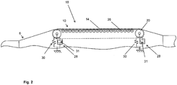
- FIGS. 1 and 2 can be removed, runs the endless circulating belt 14 via at least two rotatably mounted on the winding mandrel 6, free-running guide rollers 20 which are not driven and which form the reversal points at which the belt 14, or generally speaking, the endless traction device, deflected becomes.
- the take-off device 16 moves the inner film tube 4, which after a few revolutions of the winding device 8 with the sliver 12 wrapped as a lining tube 2 enters the discharge device 16, in a tuned to the rotational movement of the winding device 8 speed on the mandrel 6 away.
- the leadership of the inner film tube 4 is carried out in accordance with the invention exclusively on the endless belt endless belts 14 of the respective guide means 18, of which at small diameters at least 2, and may be provided at large diameters four, six or even up to eight guide means on the mandrel 6.
- the wrapped with the sliver 12 inner film tube 4 is according to the invention promoted exclusively by acting from the outside on the sliver 12 withdrawal device 16 via the winding mandrel 6 according to the invention.
- the discharge device 16 may additionally or alternatively to the two in Fig. 1 Draw off rollers 16 shown one or more driven rollers or driven circulating belts that circulate outside the circulation area of the winding device 8, eg below or laterally from the winding mandrel 6, along a non-driven traction device / belt 14 and against the surface of the lining tube 2 in this area are adjustable.
- the circulating traction means / belt 14 are positioned to the winding mandrel 6 in such a way and have such a length that they at least partially in the region of the winding device 8, ie in the region of around the inner film tube 4 around moving sliver 12, and partially in the area outside thereof circulate.
- the drive of the additional externally engageable with the guide means 18 take-off rollers or circulating belt is preferably carried out by electric motors.
- FIG. 2 further shows a schematic side view of a guide device 18 according to the invention, in which the endless belt 14 is guided over two deflecting rollers 20 arranged at the ends, between which a plurality of ball bearings 26 are arranged along a row on which the endlessly circulating belt 14 is supported, when it contacts the inside of the inner film tube 4 with its outside.
- the inclusion of at least one guide device 18 on the mandrel 6 can be done via resilient means 28, which are designed for example as a spring-damper combination with a spring element 30 and a damping element 31 and carry the respective guide device.
- the guide means 18 can also be held on the winding mandrel 6 via guides, not shown, for example, linear guides with end stop, wherein the position of a resiliently received on the winding mandrel guide means 18 is preferably adjusted so that during the production process preferably only up to half of the maximum path of movement is distracted.
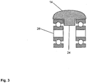
- FIG. 3 is a schematic cross-sectional view of a preferred embodiment of the ball-bearing belt according to the invention 14 shown having a central web 24.
- a ball bearing 26 is arranged, on which the belt 14 is mounted in the longitudinal direction.
- the ball bearings 26 are preferably received on a common shaft, not shown, as for example in FIG. 5 is indicated by the bolt 34.
- FIG. 4 The upper side of the belt 14 in this embodiment consists of an elastic, preferably rubber-like material, whereas on the underside of the belt 14 chain link-like reinforcing elements 22 are arranged, which for example consist of a hard plastic material such as polyamide or polycarbonate or metal.
- the reinforcing elements 22 serve to further reduce the rolling resistance of the belt 14.
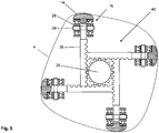
- FIG. 5 shows a schematic representation, not to scale, of an adjusting device 40 according to the invention.
- the adjusting device 40 has four guide devices 18 which are respectively fastened to a toothed rack 36 and guided via linear bearings (not shown) in such a way that they move radially by rotating a central shaft 38 can be.
- the diameter of the inner film tube 4 guided over it is changed by the rotation of the central shaft 38 of the diameter defined by the four outer sides of the belt 14.
Landscapes
- Engineering & Computer Science (AREA)
- Manufacturing & Machinery (AREA)
- General Engineering & Computer Science (AREA)
- Mechanical Engineering (AREA)
- Lining Or Joining Of Plastics Or The Like (AREA)
- Moulding By Coating Moulds (AREA)
Applications Claiming Priority (1)
| Application Number | Priority Date | Filing Date | Title |
|---|---|---|---|
| DE102015014730.7A DE102015014730A1 (de) | 2015-11-17 | 2015-11-17 | Verfahren zur Herstellung eines Auskleidungsschlauchs zur Auskleidung von Rohrleitungen sowie Vorrichtung zur Durchführung des Verfahrens |
Publications (3)
| Publication Number | Publication Date |
|---|---|
| EP3170646A2 true EP3170646A2 (fr) | 2017-05-24 |
| EP3170646A3 EP3170646A3 (fr) | 2017-08-02 |
| EP3170646B1 EP3170646B1 (fr) | 2020-12-02 |
Family
ID=57144706
Family Applications (1)
| Application Number | Title | Priority Date | Filing Date |
|---|---|---|---|
| EP16002160.6A Active EP3170646B1 (fr) | 2015-11-17 | 2016-10-06 | Procédé de fabrication d'une chemise destinée à revêtir des conduites et dispositif d'exécution du procédé |
Country Status (4)
| Country | Link |
|---|---|
| US (1) | US10377079B2 (fr) |
| EP (1) | EP3170646B1 (fr) |
| DE (1) | DE102015014730A1 (fr) |
| DK (1) | DK3170646T3 (fr) |
Families Citing this family (5)
| Publication number | Priority date | Publication date | Assignee | Title |
|---|---|---|---|---|
| CN110480994B (zh) * | 2019-08-28 | 2024-03-22 | 五行科技股份有限公司 | 一种连续增强柔性复合管中心缠绕设备机组 |
| CN111331826B (zh) * | 2020-03-02 | 2021-11-16 | 江苏凯华冷能技术有限公司 | 用于制冷系统的管路包扎装置 |
| CN112606379A (zh) * | 2020-12-28 | 2021-04-06 | 吴功城 | 一种牵引式圆管自动缠带设备 |
| CN113910594B (zh) * | 2021-09-10 | 2023-08-08 | 临海伟星新型建材有限公司 | 一种稳定牵引的缩径设备及其使用方法 |
| EP4570476A1 (fr) * | 2023-12-11 | 2025-06-18 | Brandenburger Liner GmbH & Co. KG | Procédé et dispositif de fabrication d'un revêtement tubulaire enroulé |
Citations (1)
| Publication number | Priority date | Publication date | Assignee | Title |
|---|---|---|---|---|
| DE19823714C2 (de) | 1998-05-27 | 2000-07-06 | Joachim Brandenburger | Wickelvorrichtung zum Herstellen eines Schlauches |
Family Cites Families (6)
| Publication number | Priority date | Publication date | Assignee | Title |
|---|---|---|---|---|
| US3570749A (en) * | 1968-08-09 | 1971-03-16 | Showa Denko Kk | Heavy duty bags |
| FR2097412A5 (fr) * | 1970-07-06 | 1972-03-03 | Cytec France | |
| US4120324A (en) * | 1973-08-01 | 1978-10-17 | Pahl'sche Gummi- und Asbestgesellschaft Paguag | High pressure hose composed of elastomers and embedded reinforcements |
| JPS6179634A (ja) * | 1984-09-28 | 1986-04-23 | Hitachi Zosen Corp | 繊維強化樹脂管製造装置 |
| FR2732925B1 (fr) * | 1995-04-13 | 1997-05-23 | Inst Francais Du Petrole | Dispositif pour fabriquer en continu des elements en composite |
| DE19851371A1 (de) * | 1998-11-07 | 2000-05-11 | Bielomatik Leuze & Co | Vorrichtung zum Schaffen einer Lücke in einem geschuppten Bogenstrom |
-
2015
- 2015-11-17 DE DE102015014730.7A patent/DE102015014730A1/de active Pending
-
2016
- 2016-10-06 DK DK16002160.6T patent/DK3170646T3/da active
- 2016-10-06 EP EP16002160.6A patent/EP3170646B1/fr active Active
- 2016-11-09 US US15/346,873 patent/US10377079B2/en active Active
Patent Citations (1)
| Publication number | Priority date | Publication date | Assignee | Title |
|---|---|---|---|---|
| DE19823714C2 (de) | 1998-05-27 | 2000-07-06 | Joachim Brandenburger | Wickelvorrichtung zum Herstellen eines Schlauches |
Also Published As
| Publication number | Publication date |
|---|---|
| US10377079B2 (en) | 2019-08-13 |
| DE102015014730A1 (de) | 2017-05-18 |
| EP3170646A3 (fr) | 2017-08-02 |
| US20170136684A1 (en) | 2017-05-18 |
| EP3170646B1 (fr) | 2020-12-02 |
| DK3170646T3 (da) | 2021-02-22 |
Similar Documents
| Publication | Publication Date | Title |
|---|---|---|
| EP3170646B1 (fr) | Procédé de fabrication d'une chemise destinée à revêtir des conduites et dispositif d'exécution du procédé | |
| DE102014004020A1 (de) | Winkelverstellbare Anpress- oder Nipwalze | |
| DE102015012791B4 (de) | Verfahren zur Herstellung eines Auskleidungsschlauchs zur Auskleidung von Rohrleitungen sowie eine Vorrichtung zur Durchführung des Verfahrens | |
| DE19540427A1 (de) | Vorrichtung zum Speichern und Handhaben einer Stange aus Verbundmaterial | |
| DE69626038T2 (de) | Vorrichtung und verfahren zur streckung eines filmes | |
| DE112018005407T5 (de) | Filamentwickelvorrichtung | |
| EP3178633B1 (fr) | Mandrin de bobinage dans un dispositif de bobinage destiné à fabriquer une chemise destinée à revêtir des canaux et des conduites | |
| EP2818594A2 (fr) | Câble en acier et son procédé de fabrication | |
| DE4326503A1 (de) | Verfahren zum Herstellen eines rohrförmigen Auskleidungsschlauches | |
| DE102024117237A1 (de) | Verfahren und vorrichtung zur herstellung eines gewickelten auskleidungsschlauchs | |
| DE4322114A1 (de) | Umlenkwalze | |
| DE19700785C1 (de) | Vorrichtung zur Herstellung eines Verbundschlauches | |
| DE102005050008B4 (de) | Vorrichtung und Verfahren zum Wickeln von endlosen Schraubenfedern | |
| DE2027240A1 (en) | Stretching wire or strip | |
| DE102013108184B3 (de) | Wickelmaschine und Verfahren zum Herstellen von Drahtkernen für Fahrzeugreifen | |
| DE3128111C2 (de) | Verfahren zum Herstellen von flankenoffenen Keilriemen | |
| DE2160897A1 (de) | Verfahren und Vorrichtung zur kontinuierlichen Herstellung verstärkter dichter Rohre | |
| EP4570476A1 (fr) | Procédé et dispositif de fabrication d'un revêtement tubulaire enroulé | |
| EP0876898B1 (fr) | Dispositif pour fabriquer une gaine tubulaire | |
| DE3916717A1 (de) | Trag- und stuetzvorrichtung zur halterung und unterstuetzung von bandartig flexiblen verbindungselementen | |
| EP0206310A2 (fr) | Procédé et appareil pour la fabrication d'un corps creux en matériau composite | |
| DE10002960C2 (de) | Vorrichtung und Verfahren zum Herstellen eines mehrlagigen aushärtbaren Sanierungsschlauchs | |
| DE1130752B (de) | Verfahren zum Aufbringen eines Reibbelages auf die Antriebstrommel von Foerderbandanlagen | |
| DE10242753A1 (de) | Verfahren und Vorrichtung zur Herstellung eines Verbundschlauchs | |
| DE1635653B2 (de) | Vorrichtung zur Herstellung einer Verbundstoffbahn |
Legal Events
| Date | Code | Title | Description |
|---|---|---|---|
| PUAI | Public reference made under article 153(3) epc to a published international application that has entered the european phase |
Free format text: ORIGINAL CODE: 0009012 |
|
| STAA | Information on the status of an ep patent application or granted ep patent |
Free format text: STATUS: THE APPLICATION HAS BEEN PUBLISHED |
|
| AK | Designated contracting states |
Kind code of ref document: A2 Designated state(s): AL AT BE BG CH CY CZ DE DK EE ES FI FR GB GR HR HU IE IS IT LI LT LU LV MC MK MT NL NO PL PT RO RS SE SI SK SM TR |
|
| AX | Request for extension of the european patent |
Extension state: BA ME |
|
| PUAL | Search report despatched |
Free format text: ORIGINAL CODE: 0009013 |
|
| AK | Designated contracting states |
Kind code of ref document: A3 Designated state(s): AL AT BE BG CH CY CZ DE DK EE ES FI FR GB GR HR HU IE IS IT LI LT LU LV MC MK MT NL NO PL PT RO RS SE SI SK SM TR |
|
| AX | Request for extension of the european patent |
Extension state: BA ME |
|
| RIC1 | Information provided on ipc code assigned before grant |
Ipc: B29C 63/10 20060101AFI20170628BHEP |
|
| STAA | Information on the status of an ep patent application or granted ep patent |
Free format text: STATUS: REQUEST FOR EXAMINATION WAS MADE |
|
| 17P | Request for examination filed |
Effective date: 20171128 |
|
| RBV | Designated contracting states (corrected) |
Designated state(s): AL AT BE BG CH CY CZ DE DK EE ES FI FR GB GR HR HU IE IS IT LI LT LU LV MC MK MT NL NO PL PT RO RS SE SI SK SM TR |
|
| STAA | Information on the status of an ep patent application or granted ep patent |
Free format text: STATUS: EXAMINATION IS IN PROGRESS |
|
| 17Q | First examination report despatched |
Effective date: 20200218 |
|
| RAP1 | Party data changed (applicant data changed or rights of an application transferred) |
Owner name: BRANDENBURGER, TIM Owner name: BRANDENBURGER LINER GMBH & CO. KG |
|
| GRAP | Despatch of communication of intention to grant a patent |
Free format text: ORIGINAL CODE: EPIDOSNIGR1 |
|
| STAA | Information on the status of an ep patent application or granted ep patent |
Free format text: STATUS: GRANT OF PATENT IS INTENDED |
|
| INTG | Intention to grant announced |
Effective date: 20200915 |
|
| GRAS | Grant fee paid |
Free format text: ORIGINAL CODE: EPIDOSNIGR3 |
|
| GRAA | (expected) grant |
Free format text: ORIGINAL CODE: 0009210 |
|
| STAA | Information on the status of an ep patent application or granted ep patent |
Free format text: STATUS: THE PATENT HAS BEEN GRANTED |
|
| AK | Designated contracting states |
Kind code of ref document: B1 Designated state(s): AL AT BE BG CH CY CZ DE DK EE ES FI FR GB GR HR HU IE IS IT LI LT LU LV MC MK MT NL NO PL PT RO RS SE SI SK SM TR |
|
| REG | Reference to a national code |
Ref country code: GB Ref legal event code: FG4D Free format text: NOT ENGLISH |
|
| REG | Reference to a national code |
Ref country code: AT Ref legal event code: REF Ref document number: 1340424 Country of ref document: AT Kind code of ref document: T Effective date: 20201215 Ref country code: CH Ref legal event code: EP |
|
| REG | Reference to a national code |
Ref country code: DE Ref legal event code: R096 Ref document number: 502016011812 Country of ref document: DE |
|
| REG | Reference to a national code |
Ref country code: IE Ref legal event code: FG4D Free format text: LANGUAGE OF EP DOCUMENT: GERMAN |
|
| REG | Reference to a national code |
Ref country code: NL Ref legal event code: FP |
|
| REG | Reference to a national code |
Ref country code: DK Ref legal event code: T3 Effective date: 20210219 Ref country code: FI Ref legal event code: FGE |
|
| PG25 | Lapsed in a contracting state [announced via postgrant information from national office to epo] |
Ref country code: NO Free format text: LAPSE BECAUSE OF FAILURE TO SUBMIT A TRANSLATION OF THE DESCRIPTION OR TO PAY THE FEE WITHIN THE PRESCRIBED TIME-LIMIT Effective date: 20210302 Ref country code: RS Free format text: LAPSE BECAUSE OF FAILURE TO SUBMIT A TRANSLATION OF THE DESCRIPTION OR TO PAY THE FEE WITHIN THE PRESCRIBED TIME-LIMIT Effective date: 20201202 Ref country code: GR Free format text: LAPSE BECAUSE OF FAILURE TO SUBMIT A TRANSLATION OF THE DESCRIPTION OR TO PAY THE FEE WITHIN THE PRESCRIBED TIME-LIMIT Effective date: 20210303 |
|
| PG25 | Lapsed in a contracting state [announced via postgrant information from national office to epo] |
Ref country code: BG Free format text: LAPSE BECAUSE OF FAILURE TO SUBMIT A TRANSLATION OF THE DESCRIPTION OR TO PAY THE FEE WITHIN THE PRESCRIBED TIME-LIMIT Effective date: 20210302 Ref country code: SE Free format text: LAPSE BECAUSE OF FAILURE TO SUBMIT A TRANSLATION OF THE DESCRIPTION OR TO PAY THE FEE WITHIN THE PRESCRIBED TIME-LIMIT Effective date: 20201202 Ref country code: LV Free format text: LAPSE BECAUSE OF FAILURE TO SUBMIT A TRANSLATION OF THE DESCRIPTION OR TO PAY THE FEE WITHIN THE PRESCRIBED TIME-LIMIT Effective date: 20201202 Ref country code: PL Free format text: LAPSE BECAUSE OF FAILURE TO SUBMIT A TRANSLATION OF THE DESCRIPTION OR TO PAY THE FEE WITHIN THE PRESCRIBED TIME-LIMIT Effective date: 20201202 |
|
| PG25 | Lapsed in a contracting state [announced via postgrant information from national office to epo] |
Ref country code: HR Free format text: LAPSE BECAUSE OF FAILURE TO SUBMIT A TRANSLATION OF THE DESCRIPTION OR TO PAY THE FEE WITHIN THE PRESCRIBED TIME-LIMIT Effective date: 20201202 |
|
| REG | Reference to a national code |
Ref country code: LT Ref legal event code: MG9D |
|
| PG25 | Lapsed in a contracting state [announced via postgrant information from national office to epo] |
Ref country code: RO Free format text: LAPSE BECAUSE OF FAILURE TO SUBMIT A TRANSLATION OF THE DESCRIPTION OR TO PAY THE FEE WITHIN THE PRESCRIBED TIME-LIMIT Effective date: 20201202 Ref country code: PT Free format text: LAPSE BECAUSE OF FAILURE TO SUBMIT A TRANSLATION OF THE DESCRIPTION OR TO PAY THE FEE WITHIN THE PRESCRIBED TIME-LIMIT Effective date: 20210405 Ref country code: SK Free format text: LAPSE BECAUSE OF FAILURE TO SUBMIT A TRANSLATION OF THE DESCRIPTION OR TO PAY THE FEE WITHIN THE PRESCRIBED TIME-LIMIT Effective date: 20201202 Ref country code: SM Free format text: LAPSE BECAUSE OF FAILURE TO SUBMIT A TRANSLATION OF THE DESCRIPTION OR TO PAY THE FEE WITHIN THE PRESCRIBED TIME-LIMIT Effective date: 20201202 Ref country code: LT Free format text: LAPSE BECAUSE OF FAILURE TO SUBMIT A TRANSLATION OF THE DESCRIPTION OR TO PAY THE FEE WITHIN THE PRESCRIBED TIME-LIMIT Effective date: 20201202 Ref country code: EE Free format text: LAPSE BECAUSE OF FAILURE TO SUBMIT A TRANSLATION OF THE DESCRIPTION OR TO PAY THE FEE WITHIN THE PRESCRIBED TIME-LIMIT Effective date: 20201202 |
|
| REG | Reference to a national code |
Ref country code: DE Ref legal event code: R097 Ref document number: 502016011812 Country of ref document: DE |
|
| PG25 | Lapsed in a contracting state [announced via postgrant information from national office to epo] |
Ref country code: IS Free format text: LAPSE BECAUSE OF FAILURE TO SUBMIT A TRANSLATION OF THE DESCRIPTION OR TO PAY THE FEE WITHIN THE PRESCRIBED TIME-LIMIT Effective date: 20210402 |
|
| PLBE | No opposition filed within time limit |
Free format text: ORIGINAL CODE: 0009261 |
|
| STAA | Information on the status of an ep patent application or granted ep patent |
Free format text: STATUS: NO OPPOSITION FILED WITHIN TIME LIMIT |
|
| PG25 | Lapsed in a contracting state [announced via postgrant information from national office to epo] |
Ref country code: AL Free format text: LAPSE BECAUSE OF FAILURE TO SUBMIT A TRANSLATION OF THE DESCRIPTION OR TO PAY THE FEE WITHIN THE PRESCRIBED TIME-LIMIT Effective date: 20201202 Ref country code: IT Free format text: LAPSE BECAUSE OF FAILURE TO SUBMIT A TRANSLATION OF THE DESCRIPTION OR TO PAY THE FEE WITHIN THE PRESCRIBED TIME-LIMIT Effective date: 20201202 |
|
| 26N | No opposition filed |
Effective date: 20210903 |
|
| PG25 | Lapsed in a contracting state [announced via postgrant information from national office to epo] |
Ref country code: SI Free format text: LAPSE BECAUSE OF FAILURE TO SUBMIT A TRANSLATION OF THE DESCRIPTION OR TO PAY THE FEE WITHIN THE PRESCRIBED TIME-LIMIT Effective date: 20201202 |
|
| PG25 | Lapsed in a contracting state [announced via postgrant information from national office to epo] |
Ref country code: ES Free format text: LAPSE BECAUSE OF FAILURE TO SUBMIT A TRANSLATION OF THE DESCRIPTION OR TO PAY THE FEE WITHIN THE PRESCRIBED TIME-LIMIT Effective date: 20201202 |
|
| PG25 | Lapsed in a contracting state [announced via postgrant information from national office to epo] |
Ref country code: IS Free format text: LAPSE BECAUSE OF FAILURE TO SUBMIT A TRANSLATION OF THE DESCRIPTION OR TO PAY THE FEE WITHIN THE PRESCRIBED TIME-LIMIT Effective date: 20210402 |
|
| GBPC | Gb: european patent ceased through non-payment of renewal fee |
Effective date: 20211006 |
|
| PG25 | Lapsed in a contracting state [announced via postgrant information from national office to epo] |
Ref country code: MC Free format text: LAPSE BECAUSE OF FAILURE TO SUBMIT A TRANSLATION OF THE DESCRIPTION OR TO PAY THE FEE WITHIN THE PRESCRIBED TIME-LIMIT Effective date: 20201202 |
|
| PG25 | Lapsed in a contracting state [announced via postgrant information from national office to epo] |
Ref country code: LU Free format text: LAPSE BECAUSE OF NON-PAYMENT OF DUE FEES Effective date: 20211006 Ref country code: GB Free format text: LAPSE BECAUSE OF NON-PAYMENT OF DUE FEES Effective date: 20211006 |
|
| PG25 | Lapsed in a contracting state [announced via postgrant information from national office to epo] |
Ref country code: IE Free format text: LAPSE BECAUSE OF NON-PAYMENT OF DUE FEES Effective date: 20211006 |
|
| PGFP | Annual fee paid to national office [announced via postgrant information from national office to epo] |
Ref country code: CZ Payment date: 20220926 Year of fee payment: 7 |
|
| PGFP | Annual fee paid to national office [announced via postgrant information from national office to epo] |
Ref country code: NL Payment date: 20221021 Year of fee payment: 7 |
|
| PGFP | Annual fee paid to national office [announced via postgrant information from national office to epo] |
Ref country code: CH Payment date: 20221027 Year of fee payment: 7 Ref country code: BE Payment date: 20221020 Year of fee payment: 7 |
|
| PG25 | Lapsed in a contracting state [announced via postgrant information from national office to epo] |
Ref country code: HU Free format text: LAPSE BECAUSE OF FAILURE TO SUBMIT A TRANSLATION OF THE DESCRIPTION OR TO PAY THE FEE WITHIN THE PRESCRIBED TIME-LIMIT; INVALID AB INITIO Effective date: 20161006 |
|
| P01 | Opt-out of the competence of the unified patent court (upc) registered |
Effective date: 20230417 |
|
| PG25 | Lapsed in a contracting state [announced via postgrant information from national office to epo] |
Ref country code: CY Free format text: LAPSE BECAUSE OF FAILURE TO SUBMIT A TRANSLATION OF THE DESCRIPTION OR TO PAY THE FEE WITHIN THE PRESCRIBED TIME-LIMIT Effective date: 20201202 |
|
| PG25 | Lapsed in a contracting state [announced via postgrant information from national office to epo] |
Ref country code: MK Free format text: LAPSE BECAUSE OF FAILURE TO SUBMIT A TRANSLATION OF THE DESCRIPTION OR TO PAY THE FEE WITHIN THE PRESCRIBED TIME-LIMIT Effective date: 20201202 Ref country code: CZ Free format text: LAPSE BECAUSE OF NON-PAYMENT OF DUE FEES Effective date: 20231006 |
|
| REG | Reference to a national code |
Ref country code: CH Ref legal event code: PL |
|
| REG | Reference to a national code |
Ref country code: NL Ref legal event code: MM Effective date: 20231101 |
|
| REG | Reference to a national code |
Ref country code: BE Ref legal event code: MM Effective date: 20231031 |
|
| PG25 | Lapsed in a contracting state [announced via postgrant information from national office to epo] |
Ref country code: NL Free format text: LAPSE BECAUSE OF NON-PAYMENT OF DUE FEES Effective date: 20231101 Ref country code: CH Free format text: LAPSE BECAUSE OF NON-PAYMENT OF DUE FEES Effective date: 20231031 |
|
| PG25 | Lapsed in a contracting state [announced via postgrant information from national office to epo] |
Ref country code: NL Free format text: LAPSE BECAUSE OF NON-PAYMENT OF DUE FEES Effective date: 20231101 Ref country code: CH Free format text: LAPSE BECAUSE OF NON-PAYMENT OF DUE FEES Effective date: 20231031 |
|
| PG25 | Lapsed in a contracting state [announced via postgrant information from national office to epo] |
Ref country code: BE Free format text: LAPSE BECAUSE OF NON-PAYMENT OF DUE FEES Effective date: 20231031 |
|
| PG25 | Lapsed in a contracting state [announced via postgrant information from national office to epo] |
Ref country code: MT Free format text: LAPSE BECAUSE OF FAILURE TO SUBMIT A TRANSLATION OF THE DESCRIPTION OR TO PAY THE FEE WITHIN THE PRESCRIBED TIME-LIMIT Effective date: 20201202 |
|
| PG25 | Lapsed in a contracting state [announced via postgrant information from national office to epo] |
Ref country code: TR Free format text: LAPSE BECAUSE OF FAILURE TO SUBMIT A TRANSLATION OF THE DESCRIPTION OR TO PAY THE FEE WITHIN THE PRESCRIBED TIME-LIMIT Effective date: 20201202 |
|
| REG | Reference to a national code |
Ref country code: DE Ref legal event code: R082 Ref document number: 502016011812 Country of ref document: DE Representative=s name: KESSELHUT, WOLF, DIPL.-PHYS., DE |
|
| PGFP | Annual fee paid to national office [announced via postgrant information from national office to epo] |
Ref country code: DE Payment date: 20251020 Year of fee payment: 10 |
|
| PGFP | Annual fee paid to national office [announced via postgrant information from national office to epo] |
Ref country code: AT Payment date: 20251021 Year of fee payment: 10 |
|
| PGFP | Annual fee paid to national office [announced via postgrant information from national office to epo] |
Ref country code: FI Payment date: 20251022 Year of fee payment: 10 Ref country code: DK Payment date: 20251023 Year of fee payment: 10 |
|
| PGFP | Annual fee paid to national office [announced via postgrant information from national office to epo] |
Ref country code: FR Payment date: 20251022 Year of fee payment: 10 |