EP3170665B1 - Procédé de fonctionnement d'une imprimante comprenant un cylindre tramé - Google Patents
Procédé de fonctionnement d'une imprimante comprenant un cylindre tramé Download PDFInfo
- Publication number
- EP3170665B1 EP3170665B1 EP16194540.7A EP16194540A EP3170665B1 EP 3170665 B1 EP3170665 B1 EP 3170665B1 EP 16194540 A EP16194540 A EP 16194540A EP 3170665 B1 EP3170665 B1 EP 3170665B1
- Authority
- EP
- European Patent Office
- Prior art keywords
- roller
- anilox roller
- anilox
- rider
- printing
- Prior art date
- Legal status (The legal status is an assumption and is not a legal conclusion. Google has not performed a legal analysis and makes no representation as to the accuracy of the status listed.)
- Active
Links
Images


Classifications
-
- B—PERFORMING OPERATIONS; TRANSPORTING
- B41—PRINTING; LINING MACHINES; TYPEWRITERS; STAMPS
- B41F—PRINTING MACHINES OR PRESSES
- B41F31/00—Inking arrangements or devices
- B41F31/02—Ducts, containers, supply or metering devices
- B41F31/06—Troughs or like reservoirs with immersed or partly immersed, rollers or cylinders
-
- B—PERFORMING OPERATIONS; TRANSPORTING
- B41—PRINTING; LINING MACHINES; TYPEWRITERS; STAMPS
- B41F—PRINTING MACHINES OR PRESSES
- B41F31/00—Inking arrangements or devices
- B41F31/26—Construction of inking rollers
-
- B—PERFORMING OPERATIONS; TRANSPORTING
- B41—PRINTING; LINING MACHINES; TYPEWRITERS; STAMPS
- B41F—PRINTING MACHINES OR PRESSES
- B41F31/00—Inking arrangements or devices
- B41F31/02—Ducts, containers, supply or metering devices
- B41F31/04—Ducts, containers, supply or metering devices with duct-blades or like metering devices
-
- B—PERFORMING OPERATIONS; TRANSPORTING
- B41—PRINTING; LINING MACHINES; TYPEWRITERS; STAMPS
- B41N—PRINTING PLATES OR FOILS; MATERIALS FOR SURFACES USED IN PRINTING MACHINES FOR PRINTING, INKING, DAMPING, OR THE LIKE; PREPARING SUCH SURFACES FOR USE AND CONSERVING THEM
- B41N7/00—Shells for rollers of printing machines
- B41N7/06—Shells for rollers of printing machines for inking rollers
Definitions
- the present invention relates to a method for operating a printing press according to the preamble of claim 1.
- the cells form a recessed surface portion of the anilox surface of the anilox roller and the webs lying between the cells form in their entirety a raised surface portion of the screen surface.
- no statement is made as to the size of the raised surface area.
- a problem not dealt with by the prior art mentioned - the Offenlegungsschrift and the Internet article - is the very narrow adjustment range of the color density in anilox inking units.
- Some print jobs require a comparatively high color density.
- ink transfer is enhanced by raising the temperature of the anilox roller, which is connected to a temperature control device.
- the temperature of the anilox roller can only be increased up to an upper limit, because if the upper limit is exceeded there would be a risk of the detergents used in the anilox inking unit igniting spontaneously. Therefore, the only option left is to replace the anilox roller used in the printing press with another one that has a larger scoop volume.
- this anilox roller change is associated with machine downtimes.
- WO2009082225A2 a method is described in which an anilox roller is used, the webs of which occupy less than 10%, in one embodiment less than 5% or 3% and preferably less than 2% of the entire roller surface.
- EP1911586A2 describes a short inking unit which has an anilox roller and an inking roller, with which a roller with a relatively soft surface is in contact, with which a roller with a relatively hard surface is in contact.
- a metering roller is shown with a grid structure, the bottom area of which is 20% in one embodiment and 44% in another embodiment.
- the present invention is based on the object of specifying a method for operating a printing press in which machine downtimes caused by changing anilox rollers are required less frequently.
- the invention is based on the finding that the density adjustment range of an anilox inking unit can be expanded through the interaction of the rider roller with a sufficiently large raised surface area. If the raised surface area is sufficiently large, the rider roller not only equalizes the ink transfer, but also increases the ink transfer and thus expands the density control range. Investigations have shown that under practical conditions the raised area proportion is at least 10% of the grid area should be. This means, for example, that the ratio of the opening width to the land width of the grid area should not exceed 9:1.
- the opening width/land width ratio is also referred to as the so-called cell/land ratio, particularly in the case of cell screening.
- the anilox roller can be engraved with a line of 90 lines per centimeter and the engraving can be what is known as a hatch, in which instead of the cells there are one or more grooves running in a helical shape around the anilox roller.
- the grid spacing or the so-called cell width is 0.11 mm.
- the groove width (opening width) is between 80 ⁇ m and 90 ⁇ m and the land width is between 20 ⁇ m and 30 ⁇ m. That is, if at a certain location the groove width is 80 ⁇ m, then the associated land width is 30 ⁇ m, and if at another location the groove width is 90 ⁇ m, then at the associated location the land width is 20 ⁇ m.
- the raised area is 15% to 35% of the grid area.
- an anilox roller is used as the anilox roller, in which the anilox surface has a ruling of at most 135 lines per centimeter.
- an anilox roller is used as the anilox roller, the anilox surface of which is a hazel surface, in which the raised surface area is formed by a web or several webs and the recessed surface area is formed by a groove or several grooves and each web and each groove is helically shaped runs.
- the rider roller is kept in rolling contact exclusively with the anilox roller in the first printing operating mode.
- the rider roller is held in rolling contact with the anilox roller by a spring in the first printing operating mode.
- the rotation of the rider roller is driven exclusively by the anilox roller, with the anilox roller driving the rider roller via peripheral surface friction.
- no traversing roller or rider roller is used as the rider roller, but rather an axially stationary roller.
- a printing press 1 is shown with an anilox inking unit, which comprises an anilox roller 2 and an inking roller 3 lying against it.
- the inking roller 3 rolls on a printing forme cylinder 4, which is moistened by a dampening unit 5 and rests against a rubber blanket cylinder, which is not shown in the drawing.
- the printing machine 1 is an anilox offset sheet-fed printing machine.
- a feed device 6 for supplying the fluid - here specifically the color - to the anilox roller 2 at.
- the feed device 6 comprises a bowl-shaped container 7 with a doctor blade 8 and a pivoting rear wall 9.
- the level of the ink in the container 7 is selectively raised above a cutting edge of the doctor blade 8, which is required for the printing operation, and below the cutting edge is lowered in order to be able to turn off the feed device 6 from the anilox roller 2 after the printing operation, without the ink overflowing from the container 7.
- the inking roller 3 forms a removal device which removes the color from the anilox roller 2 .
- the invention can be used not only in an anilox offset printing unit, but also in a flexographic printing unit.
- a flexographic printing unit can be part of an offset printing machine, for example as a varnishing unit, which has a number of offset printing units in addition to the flexographic printing unit.
- a printing forme cylinder is arranged, with which the anilox roller 2 is in rolling contact during printing, and this printing forme cylinder forms the pick-up device.
- the inking roller 3 and the rubber blanket cylinder mentioned in connection with offset printing are omitted in the flexographic printing unit.
- the anilox roller 2 and the inking roller 3 are rotated in a manner coordinated with one another, as required in EP 1 291 176 B1 described procedure is inherent.
- EP 1 291 176 B1 By applying the technical measures EP 1 291 176 B1 Within the scope of the present invention, it is prevented that a particularly rough line pattern of the anilox roller 2 has a negative effect on the printed image and shows up there in the form of uneven coloring. Due to the offset superimposition of the accumulations of color on the Inking roller 3 doubles the fineness of the screening, so to speak, and closed areas are achieved in the printed image, which would otherwise only be possible with an anilox roller 2 with finer lines.
- an anilox roller 2 with a ruling of less than 135 lines per centimeter can be used without any problems, for example an anilox roller 2 with a ruling of 110 lines per centimeter.
- the anilox roller 2 rotates in the direction of rotation 10.
- a rider roller 11 is arranged in this direction of rotation after the feed device 6 and before the inking roller 3.
- a roller group 12 is arranged.
- the rider roller 11 has a peripheral surface made of a soft and ink-friendly rubber material and is mounted at both ends in a roller lock 13 which is arranged on a bearing lever 14 which can be pivoted by an actuator 15, for example by a pneumatic cylinder.
- a control device 24 controls the actuator 15 according to a program running in the control device 24 .
- Each roller lock 13 includes a spring 16 for pressing the rider roller 11 against the anilox roller 2.
- This spring system is advantageous in terms of its readjustment effect, which compensates for changes in the diameter of the rider roller 11 caused by aging or by changing the rollers.
- the roller covering of the rider roller 11, which is made of rubber or a rubber-like plastic, can shrink or swell over time, as a result of which the roller diameter can change. Due to wear, the rider roll 11 can be replaced by a replacement roll whose diameter differs slightly from that of the original rider roll 11 due to tolerances.
- the roll cover of the replacement roll can be slightly softer or harder than the roll cover of the original rider roll 11; such differences in the compressibility of the rolls are also compensated for by the spring system.
- the rider roller 11 is in rolling contact exclusively with the anilox roller 2, that is to say no other roller or cylinder is in contact with the rider roller 11.
- figure 1 shows a first printing mode of operation, in which on each side of the machine (drive side, operator side) the bearing lever 14 with the roller lock 13 and the the rider roller 11 rotatably mounted therein is pivoted towards the anilox roller 2 and the respective spring 16 presses the rider roller 11 against the anilox roller 2 .
- the actuator 15 is extended accordingly.
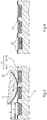
- the rolling of the rider roller 11 on the anilox roller 2 is shown in a greatly simplified representation, the components involved not being shown in their true size ratio to one another for better understanding.
- the anilox roller 2 has an anilox surface 17 which extends in a circular ring over the entire circumference of the anilox roller 2, which cannot be seen in the section shown.
- the screen surface 17 does not have to extend over the entire axial length of the screen roller 2 .
- the grid surface 17 consists of a groove 18 and a web 19, which delimits the groove 18 and form the side walls.
- the groove 18 and the web 19 run parallel to one another in helical form or helically around the axis of rotation of the anilox roller 2, which axis of rotation is perpendicular to the plane of the image figure 3 is oriented.
- the direction of extension of the groove 18 and the ridge 19 is oblique relative to the plane of the image figure 3 .
- the grid structure formed by the groove 18 and the web 19 resembles a thread, with figure 3 three courses of this "thread" are shown. Such a grid structure is also referred to as a hash.
- the ridge 19 forms a raised surface portion 20 of the grid surface 17 and the groove 18 a recessed surface portion 21 and both surface portions 20, 21 together result in the entire grid surface 17.
- the grid structure would have the form of a multiple thread and the raised surface portion 20 would be formed by the two webs 19 together and the recessed surface portion 21 by the two grooves 18 together .
- the raised surface portion 20 is at least 10% of the entire grid surface 17, so that the recessed surface portion 21 is at most 90% of the grid surface 17.
- the raised surface area 20 - the so-called contact area - can be more than 15% and less than 35% of the entire grid area 17, with a ridge width S of the ridge corresponding to 15% to 35% of a cell width Z, which is the sum of the ridge width S and a Groove width R of the groove 18 is.
- figure 3 shows that the rider roller 11, when rolling over the groove 18, removes color from this and, after a few revolutions, has a closed color film 22 on its peripheral surface.
- the rider roller 11 not only removes ink from the groove 18, but also deposits the extracted ink again on the roof surface of the web 19 due to the splitting back, so that the entire screen surface 17 including its raised surface area 20 is colored after the rider roller 11 has been rolled over it is like this in figure 4 is shown.
- the amount of ink 23 deposited on the web 19 has the effect that the anilox surface 17 of the anilox roller 2 is in principle completely covered with ink and correspondingly more ink is transferred to the inking roller 3 .
- the anilox roller 2 can thus transfer more ink to the inking roller 3 per unit area of the anilox surface 17 than would be possible without the rider roller 11 .
- the rider roller 11 is driven in rotation exclusively by the anilox roller 2, i.e. there is no auxiliary drive provided specially for the rider roller 11 and there is no other roller apart from the anilox roller 2 that rests on the rider roller 11 and this drives via peripheral surface friction.
- the rubber covering of the rider roller 11 presses into the grid structure of the anilox roller 2 somewhat due to the roller pressure in the nip of the two rollers 2, 11, which increases the friction and the rider roller 11 runs with the anilox roller 2 with virtually no slippage.
- the rider roller 11 does not carry out any axial reciprocating movement, because such an oscillating movement would impair the desired build-up of color on the roof surface of the web 19.
- FIG 5 a diagram is shown whose ordinate represents the color density of the color black in the printed image.
- the bar on the left in the diagram represents the density adjustment range that is achieved in the first printing operating mode using the rider roller 11 and ranges from 1.82 to 2.41.
- the color density can be adjusted within this range solely by increasing or reducing the temperature control of the anilox roller 2 .
- An existing temperature control for the anilox roller 2 with a temperature control circuit, in which the anilox roller 2 is involved, is for reasons of graphical simplification in the Figures 1 and 2 not shown.
- FIG 2 a second printing operating mode is shown, in which the rider roller 11 is switched off from the anilox roller 2 and is passive.
- the actuator 15 linked to the bearing lever 14 is retracted to such an extent that the spring 16 is no longer able to press the rider roller 11 against the anilox roller 2 and the two rollers 2, 11 are out of contact with one another.
- the second print mode of operation is intended for a print job that requires a lower color density than the print job for which the first print mode of operation is intended.
- the right bar in the chart according to figure 5 represents the density adjustment range in the second printing mode of operation, this density adjustment range being from 1.48 to 2.06.
- the density adjustment range in the second print operating mode extends down to lower color density values than the density adjustment range in the first print operating mode (left bar).
- the ink transfer from the anilox roller 2 to the inking roller 3 can be adjusted solely by changing the anilox roller temperature control. Increasing the anilox roller temperature reduces the ink viscosity and correspondingly more ink is transferred from the anilox roller 2 to the pick-up device (ink applicator roller 3). By lowering the anilox roller temperature, the viscosity of the fluid (ink) is increased and accordingly less fluid is transferred to the pick-up device.
- print jobs can be printed in this mode that require such a low ink density that the first printing mode is no longer suitable, for the following reason:
- the temperature of the anilox roller 2 would have to be lowered so much in order to achieve the low color density that condensation problems would occur on the anilox roller 2, through which the print quality would be impaired. It is therefore advantageous that the anilox roller temperature can be kept above the critical lower limit by switching off the rider roller 11 .
- the amount of fluid transferred determines the color density that can be measured in the printed image on the substrate.
- An advantage of the method according to the invention is that the density control range represented by the right-hand bar is expanded by switching on the rider roller 11 by the density control range represented by the left-hand value bar, which means that changing the anilox roller 2 to change the effective scoop volume of the anilox roller 2 is less necessary and the machine downtimes associated with changing anilox rollers can be minimized.
- figure 6 1 shows the flow chart of the operating method of the printing machine 1, with the steps of the program running in the control device 24 corresponding to this flow chart.
- a first method step 101 the color density or coloring is measured.
- step 104 If it is determined in the fourth step 104 that the rider roller 11 is not yet in contact with the anilox roller 2, then in a sixth step 106 the rider roller 11 is placed against the anilox roller 2 and the anilox roller temperature is reduced. Then, in a seventh step 107, continuous printing begins.
- an eighth step 108 it is decided whether the coloration is too high or not. If the inking is not too great, then continuous printing begins in the seventh step 107 . However, if the measurement in the eighth step 108 shows that the coloring is too high, then checked or decided in a ninth step whether the current anilox roller temperature already corresponds to the lower control limit for the anilox roller temperature or not. If the lower setting limit has already been reached, then in a tenth step 110 it is checked whether the rider roller 11 is already in contact with the anilox roller 2 or not.
- step 111 the rider roller 11 is switched off from the anilox roller 2, that is, from the first printing operating mode ( figure 1 ) to the second printing operation mode ( figure 2 ) is changed and the anilox roller temperature is increased on the temperature control device. Then the continuous printing 107 is started.
- the anilox roller temperature is adjusted by lowering the anilox roller temperature. Then the continuous printing 107 is started.
- the temperature of the anilox roller is adjusted by increasing the anilox roller temperature. After that, production run 107 will also begin. If it is determined in the tenth step 110 that the rider roller 11 is not in contact with the anilox roller 2, i.e. that the anilox inking unit is operated in the second printing operating mode, then in a thirteenth step 113 the anilox roller is replaced (for a replacement anilox roller with a lower scoop volume) and/or the color adjusted, for example replaced by another color with a different pigmentation. Then the continuous printing 107 is started.
Landscapes
- Inking, Control Or Cleaning Of Printing Machines (AREA)
Claims (8)
- Procédé de fonctionnement d'une machine à imprimer (1), comprenant un rouleau tramé (2), un dispositif d'alimentation (6) pour amener un fluide au rouleau tramé (2), un dispositif de prélèvement pour prélever le fluide du rouleau tramé (2) et un rouleau chargeur (11), le rouleau tramé (2) ayant une surface tramée (17), qui se compose d'une partie de surface en relief (20) et d'une partie de surface en creux (21), le dispositif de prélèvement étant un rouleau (3) ou un cylindre et le rouleau chargeur (11) étant disposé dans le sens de rotation (10) du rouleau tramé (2) en aval du dispositif d'amenée (6) et en amont du dispositif de prélèvement,
caractérisé en ce
que l'on utilise comme rouleau tramé (2) un rouleau tramé (2) pour lequel la partie de surface en relief (20) représente au moins 10 % de la surface tramée (17), et en ce que le rouleau chargeur (11) est maintenu en contact de roulement avec le rouleau tramé (2) lors de l'impression dans un premier mode de fonctionnement de l'impression et hors de contact de roulement avec le rouleau tramé (2) lors de l'impression dans un deuxième mode de fonctionnement de l'impression. - Procédé selon la revendication 1,
caractérisé en ce
que la partie de surface en relief (20) représente 15 % à 35 % de la surface tramée (17). - Procédé selon la revendication 1 ou 2,
caractérisé en ce
que l'on utilise comme rouleau tramé (2) un rouleau tramé (2) pour lequel la surface tramée (17) présente une linéature de 135 lignes par centimètre au maximum. - Procédé selon l'une des revendications 1 à 3,
caractérisé en ce
que l'on utilise comme rouleau tramé (2) un rouleau tramé (2) dont la surface tramée (17) est une surface en hachures, la partie de surface en relief (20) étant formée par une ou plusieurs nervures (19) et la partie de surface en creux (21) par une ou plusieurs rainures (18), et que chaque nervure (19) et chaque rainure (18) présente une forme hélicoïdale. - Procédé selon l'une des revendications 1 à 4,
caractérisé en ce
que le rouleau chargeur (11) est maintenu en contact de roulement exclusivement avec le rouleau tramé (2) dans le premier mode de fonctionnement d'impression. - Procédé selon l'une des revendications 1 à 5,
caractérisé en ce
que le rouleau chargeur (11) est maintenu en contact de roulement avec le rouleau tramé (2) par un ressort (16) dans le premier mode de fonctionnement d'impression. - Procédé selon l'une des revendications 1 à 6,
caractérisé en ce
que, dans le premier mode de fonctionnement d'impression, la rotation du rouleau chargeur (11) est entraînée exclusivement par le rouleau tramé (2), le rouleau tramé (2) entraînant le rouleau chargeur (11) par frottement circonférentiel de surface. - Procédé selon l'une des revendications 1 à 7,
caractérisé en ce
que l'on utilise comme rouleau chargeur (11) non pas un rouleau frotteur ou un rouleau distributeur, mais un rouleau (11) immobile dans le sens axial.
Applications Claiming Priority (1)
| Application Number | Priority Date | Filing Date | Title |
|---|---|---|---|
| DE102015222908.4A DE102015222908A1 (de) | 2015-11-20 | 2015-11-20 | Verfahren zum Betreiben einer Druckmaschine |
Publications (2)
| Publication Number | Publication Date |
|---|---|
| EP3170665A1 EP3170665A1 (fr) | 2017-05-24 |
| EP3170665B1 true EP3170665B1 (fr) | 2022-03-30 |
Family
ID=57153383
Family Applications (1)
| Application Number | Title | Priority Date | Filing Date |
|---|---|---|---|
| EP16194540.7A Active EP3170665B1 (fr) | 2015-11-20 | 2016-10-19 | Procédé de fonctionnement d'une imprimante comprenant un cylindre tramé |
Country Status (3)
| Country | Link |
|---|---|
| EP (1) | EP3170665B1 (fr) |
| CN (1) | CN106985513B (fr) |
| DE (1) | DE102015222908A1 (fr) |
Citations (1)
| Publication number | Priority date | Publication date | Assignee | Title |
|---|---|---|---|---|
| US4862799A (en) * | 1987-11-13 | 1989-09-05 | Rockwell International Corporation | Copper coated anodized aluminum ink metering roller |
Family Cites Families (10)
| Publication number | Priority date | Publication date | Assignee | Title |
|---|---|---|---|---|
| DE10144563A1 (de) | 2001-09-11 | 2003-03-27 | Heidelberger Druckmasch Ag | Druckmaschine und Verfahren zum Betreiben eines Farbwerks |
| DE102006004568A1 (de) | 2006-02-01 | 2007-08-02 | Koenig & Bauer Aktiengesellschaft | Kurzfarbwerk für eine Druckmaschine |
| DE102007041203A1 (de) * | 2006-10-11 | 2008-04-24 | Man Roland Druckmaschinen Ag | Kurzfarbwerk für eine Verarbeitungsmaschine |
| DE102007059912A1 (de) * | 2007-12-12 | 2009-06-18 | Koenig & Bauer Aktiengesellschaft | Druckwerk einer Rotationsdruckmaschine zur Erzeugung von Irisdrucken |
| PT2121339E (pt) * | 2007-12-21 | 2011-06-09 | Apex Europ B V | Método para imprimir um substrato usando um rolo anilox, um rolo anilox para um método de impressão e um aparelho de impressão. |
| DE102008043957A1 (de) * | 2008-11-21 | 2010-05-27 | Koenig & Bauer Aktiengesellschaft | Rasterwalze und Verfahren zu deren Herstellung |
| CN101817252B (zh) * | 2010-04-08 | 2012-01-25 | 云南侨通包装印刷有限公司 | 一种陶瓷网纹窜水辊及制作方法 |
| CN201889960U (zh) * | 2010-11-11 | 2011-07-06 | 上海运城制版有限公司 | 蛇形网点陶瓷网纹辊 |
| WO2014162994A1 (fr) * | 2013-04-04 | 2014-10-09 | 株式会社小森コーポレーション | Cylindre d'alimentation en encre et procédé de fabrication correspondant |
| DE102014225559A1 (de) * | 2014-01-23 | 2015-07-23 | Heidelberger Druckmaschinen Ag | Rasterwalze |
-
2015
- 2015-11-20 DE DE102015222908.4A patent/DE102015222908A1/de not_active Withdrawn
-
2016
- 2016-10-19 EP EP16194540.7A patent/EP3170665B1/fr active Active
- 2016-10-26 CN CN201610944501.4A patent/CN106985513B/zh active Active
Patent Citations (1)
| Publication number | Priority date | Publication date | Assignee | Title |
|---|---|---|---|---|
| US4862799A (en) * | 1987-11-13 | 1989-09-05 | Rockwell International Corporation | Copper coated anodized aluminum ink metering roller |
Also Published As
| Publication number | Publication date |
|---|---|
| CN106985513B (zh) | 2020-05-22 |
| EP3170665A1 (fr) | 2017-05-24 |
| DE102015222908A1 (de) | 2017-06-08 |
| CN106985513A (zh) | 2017-07-28 |
Similar Documents
| Publication | Publication Date | Title |
|---|---|---|
| EP0064270B1 (fr) | Dispositif d'encrage | |
| DE19731003B4 (de) | Kurzfarbwerk | |
| DE2526466A1 (de) | Farbauftragsvorrichtung fuer eine tiefdruckmaschine | |
| EP2703162B1 (fr) | Procédé et dispositif d'impression de matériau d'impression | |
| EP1013418B1 (fr) | Dispositif d'encrage | |
| EP2242651A2 (fr) | Rotative d'impression à plat | |
| EP1820648B1 (fr) | Dispositif d'encrage et procédé de détermination d'un état de configuration de celui-ci | |
| WO2007135155A2 (fr) | Dispositifs disposés dans un groupe d'impression d'une presse rotative | |
| DE2259085A1 (de) | Farbwerk fuer flachdruckmaschinen | |
| EP2019752A1 (fr) | Mécanisme d'encrage de presse rotative comprenant un cylindre porte-film | |
| EP1291177B1 (fr) | Dispositif pour contrôler le transfert d'un liquide entre deux rouleaux | |
| DE10057051B4 (de) | Verfahren zum Anfahren einer Druckmaschine | |
| EP3170665B1 (fr) | Procédé de fonctionnement d'une imprimante comprenant un cylindre tramé | |
| DE102006041881B4 (de) | Farbdosiereinrichtung eines Druckwerks und Verfahren zur Steuerung der Farbdosiereinrichtung | |
| EP1467865A2 (fr) | Dispositif d'encrage d'un rouleau | |
| DE69834752T2 (de) | Farbzuführrolle für drucker | |
| DE202004006800U1 (de) | Walze für Druckmaschinen, Farbwerk mit Walze, Druckmaschine mit Farbwerk | |
| DE8224875U1 (de) | Farbwerk für Offsetdruckmaschinen | |
| DE102005013634A1 (de) | Verfahren zum Betrieb einer Druckmaschine | |
| DE19727387C1 (de) | Verfahren und Vorrichtung zur Steuerung der Farbzufuhr bei Druckmaschinen | |
| DE102006042590B4 (de) | Rotationsdruckmaschine mit mindestens einem eine Farbstromtrennwalze aufweisenden Farbwerk | |
| EP2090431B1 (fr) | Procédé et appareil pour commander un dispositif de mouillage d'une machine d'impression | |
| DE102004056631B3 (de) | Tiefdruckwerk mit einem Abstreifer für den Formzylinder | |
| DE10241739A1 (de) | Mehrfarben-Druckwerk | |
| DE102009046976A1 (de) | Druckwerk und Verfahren zum Betreiben desselben |
Legal Events
| Date | Code | Title | Description |
|---|---|---|---|
| PUAI | Public reference made under article 153(3) epc to a published international application that has entered the european phase |
Free format text: ORIGINAL CODE: 0009012 |
|
| STAA | Information on the status of an ep patent application or granted ep patent |
Free format text: STATUS: THE APPLICATION HAS BEEN PUBLISHED |
|
| AK | Designated contracting states |
Kind code of ref document: A1 Designated state(s): AL AT BE BG CH CY CZ DE DK EE ES FI FR GB GR HR HU IE IS IT LI LT LU LV MC MK MT NL NO PL PT RO RS SE SI SK SM TR |
|
| AX | Request for extension of the european patent |
Extension state: BA ME |
|
| STAA | Information on the status of an ep patent application or granted ep patent |
Free format text: STATUS: REQUEST FOR EXAMINATION WAS MADE |
|
| 17P | Request for examination filed |
Effective date: 20171124 |
|
| RBV | Designated contracting states (corrected) |
Designated state(s): AL AT BE BG CH CY CZ DE DK EE ES FI FR GB GR HR HU IE IS IT LI LT LU LV MC MK MT NL NO PL PT RO RS SE SI SK SM TR |
|
| RAP1 | Party data changed (applicant data changed or rights of an application transferred) |
Owner name: HEIDELBERGER DRUCKMASCHINEN AG |
|
| STAA | Information on the status of an ep patent application or granted ep patent |
Free format text: STATUS: EXAMINATION IS IN PROGRESS |
|
| 17Q | First examination report despatched |
Effective date: 20200724 |
|
| RAP1 | Party data changed (applicant data changed or rights of an application transferred) |
Owner name: HEIDELBERGER DRUCKMASCHINEN INTELLECTUAL PROPERTY AG & CO. KG |
|
| GRAP | Despatch of communication of intention to grant a patent |
Free format text: ORIGINAL CODE: EPIDOSNIGR1 |
|
| STAA | Information on the status of an ep patent application or granted ep patent |
Free format text: STATUS: GRANT OF PATENT IS INTENDED |
|
| INTG | Intention to grant announced |
Effective date: 20211124 |
|
| GRAS | Grant fee paid |
Free format text: ORIGINAL CODE: EPIDOSNIGR3 |
|
| GRAA | (expected) grant |
Free format text: ORIGINAL CODE: 0009210 |
|
| STAA | Information on the status of an ep patent application or granted ep patent |
Free format text: STATUS: THE PATENT HAS BEEN GRANTED |
|
| AK | Designated contracting states |
Kind code of ref document: B1 Designated state(s): AL AT BE BG CH CY CZ DE DK EE ES FI FR GB GR HR HU IE IS IT LI LT LU LV MC MK MT NL NO PL PT RO RS SE SI SK SM TR |
|
| REG | Reference to a national code |
Ref country code: GB Ref legal event code: FG4D Free format text: NOT ENGLISH |
|
| REG | Reference to a national code |
Ref country code: CH Ref legal event code: EP |
|
| REG | Reference to a national code |
Ref country code: AT Ref legal event code: REF Ref document number: 1478822 Country of ref document: AT Kind code of ref document: T Effective date: 20220415 |
|
| REG | Reference to a national code |
Ref country code: DE Ref legal event code: R096 Ref document number: 502016014696 Country of ref document: DE |
|
| REG | Reference to a national code |
Ref country code: IE Ref legal event code: FG4D Free format text: LANGUAGE OF EP DOCUMENT: GERMAN |
|
| REG | Reference to a national code |
Ref country code: LT Ref legal event code: MG9D |
|
| PG25 | Lapsed in a contracting state [announced via postgrant information from national office to epo] |
Ref country code: SE Free format text: LAPSE BECAUSE OF FAILURE TO SUBMIT A TRANSLATION OF THE DESCRIPTION OR TO PAY THE FEE WITHIN THE PRESCRIBED TIME-LIMIT Effective date: 20220330 Ref country code: RS Free format text: LAPSE BECAUSE OF FAILURE TO SUBMIT A TRANSLATION OF THE DESCRIPTION OR TO PAY THE FEE WITHIN THE PRESCRIBED TIME-LIMIT Effective date: 20220330 Ref country code: NO Free format text: LAPSE BECAUSE OF FAILURE TO SUBMIT A TRANSLATION OF THE DESCRIPTION OR TO PAY THE FEE WITHIN THE PRESCRIBED TIME-LIMIT Effective date: 20220630 Ref country code: LT Free format text: LAPSE BECAUSE OF FAILURE TO SUBMIT A TRANSLATION OF THE DESCRIPTION OR TO PAY THE FEE WITHIN THE PRESCRIBED TIME-LIMIT Effective date: 20220330 Ref country code: HR Free format text: LAPSE BECAUSE OF FAILURE TO SUBMIT A TRANSLATION OF THE DESCRIPTION OR TO PAY THE FEE WITHIN THE PRESCRIBED TIME-LIMIT Effective date: 20220330 Ref country code: BG Free format text: LAPSE BECAUSE OF FAILURE TO SUBMIT A TRANSLATION OF THE DESCRIPTION OR TO PAY THE FEE WITHIN THE PRESCRIBED TIME-LIMIT Effective date: 20220630 |
|
| REG | Reference to a national code |
Ref country code: NL Ref legal event code: MP Effective date: 20220330 |
|
| PG25 | Lapsed in a contracting state [announced via postgrant information from national office to epo] |
Ref country code: LV Free format text: LAPSE BECAUSE OF FAILURE TO SUBMIT A TRANSLATION OF THE DESCRIPTION OR TO PAY THE FEE WITHIN THE PRESCRIBED TIME-LIMIT Effective date: 20220330 Ref country code: GR Free format text: LAPSE BECAUSE OF FAILURE TO SUBMIT A TRANSLATION OF THE DESCRIPTION OR TO PAY THE FEE WITHIN THE PRESCRIBED TIME-LIMIT Effective date: 20220701 Ref country code: FI Free format text: LAPSE BECAUSE OF FAILURE TO SUBMIT A TRANSLATION OF THE DESCRIPTION OR TO PAY THE FEE WITHIN THE PRESCRIBED TIME-LIMIT Effective date: 20220330 |
|
| PG25 | Lapsed in a contracting state [announced via postgrant information from national office to epo] |
Ref country code: NL Free format text: LAPSE BECAUSE OF FAILURE TO SUBMIT A TRANSLATION OF THE DESCRIPTION OR TO PAY THE FEE WITHIN THE PRESCRIBED TIME-LIMIT Effective date: 20220330 |
|
| PG25 | Lapsed in a contracting state [announced via postgrant information from national office to epo] |
Ref country code: SM Free format text: LAPSE BECAUSE OF FAILURE TO SUBMIT A TRANSLATION OF THE DESCRIPTION OR TO PAY THE FEE WITHIN THE PRESCRIBED TIME-LIMIT Effective date: 20220330 Ref country code: SK Free format text: LAPSE BECAUSE OF FAILURE TO SUBMIT A TRANSLATION OF THE DESCRIPTION OR TO PAY THE FEE WITHIN THE PRESCRIBED TIME-LIMIT Effective date: 20220330 Ref country code: RO Free format text: LAPSE BECAUSE OF FAILURE TO SUBMIT A TRANSLATION OF THE DESCRIPTION OR TO PAY THE FEE WITHIN THE PRESCRIBED TIME-LIMIT Effective date: 20220330 Ref country code: PT Free format text: LAPSE BECAUSE OF FAILURE TO SUBMIT A TRANSLATION OF THE DESCRIPTION OR TO PAY THE FEE WITHIN THE PRESCRIBED TIME-LIMIT Effective date: 20220801 Ref country code: ES Free format text: LAPSE BECAUSE OF FAILURE TO SUBMIT A TRANSLATION OF THE DESCRIPTION OR TO PAY THE FEE WITHIN THE PRESCRIBED TIME-LIMIT Effective date: 20220330 Ref country code: EE Free format text: LAPSE BECAUSE OF FAILURE TO SUBMIT A TRANSLATION OF THE DESCRIPTION OR TO PAY THE FEE WITHIN THE PRESCRIBED TIME-LIMIT Effective date: 20220330 Ref country code: CZ Free format text: LAPSE BECAUSE OF FAILURE TO SUBMIT A TRANSLATION OF THE DESCRIPTION OR TO PAY THE FEE WITHIN THE PRESCRIBED TIME-LIMIT Effective date: 20220330 |
|
| PG25 | Lapsed in a contracting state [announced via postgrant information from national office to epo] |
Ref country code: PL Free format text: LAPSE BECAUSE OF FAILURE TO SUBMIT A TRANSLATION OF THE DESCRIPTION OR TO PAY THE FEE WITHIN THE PRESCRIBED TIME-LIMIT Effective date: 20220330 Ref country code: IS Free format text: LAPSE BECAUSE OF FAILURE TO SUBMIT A TRANSLATION OF THE DESCRIPTION OR TO PAY THE FEE WITHIN THE PRESCRIBED TIME-LIMIT Effective date: 20220730 Ref country code: AL Free format text: LAPSE BECAUSE OF FAILURE TO SUBMIT A TRANSLATION OF THE DESCRIPTION OR TO PAY THE FEE WITHIN THE PRESCRIBED TIME-LIMIT Effective date: 20220330 |
|
| REG | Reference to a national code |
Ref country code: DE Ref legal event code: R097 Ref document number: 502016014696 Country of ref document: DE |
|
| PG25 | Lapsed in a contracting state [announced via postgrant information from national office to epo] |
Ref country code: DK Free format text: LAPSE BECAUSE OF FAILURE TO SUBMIT A TRANSLATION OF THE DESCRIPTION OR TO PAY THE FEE WITHIN THE PRESCRIBED TIME-LIMIT Effective date: 20220330 |
|
| PLBE | No opposition filed within time limit |
Free format text: ORIGINAL CODE: 0009261 |
|
| STAA | Information on the status of an ep patent application or granted ep patent |
Free format text: STATUS: NO OPPOSITION FILED WITHIN TIME LIMIT |
|
| 26N | No opposition filed |
Effective date: 20230103 |
|
| PG25 | Lapsed in a contracting state [announced via postgrant information from national office to epo] |
Ref country code: SI Free format text: LAPSE BECAUSE OF FAILURE TO SUBMIT A TRANSLATION OF THE DESCRIPTION OR TO PAY THE FEE WITHIN THE PRESCRIBED TIME-LIMIT Effective date: 20220330 Ref country code: MC Free format text: LAPSE BECAUSE OF FAILURE TO SUBMIT A TRANSLATION OF THE DESCRIPTION OR TO PAY THE FEE WITHIN THE PRESCRIBED TIME-LIMIT Effective date: 20220330 |
|
| REG | Reference to a national code |
Ref country code: CH Ref legal event code: PL |
|
| P01 | Opt-out of the competence of the unified patent court (upc) registered |
Effective date: 20230427 |
|
| REG | Reference to a national code |
Ref country code: BE Ref legal event code: MM Effective date: 20221031 |
|
| GBPC | Gb: european patent ceased through non-payment of renewal fee |
Effective date: 20221019 |
|
| PG25 | Lapsed in a contracting state [announced via postgrant information from national office to epo] |
Ref country code: LU Free format text: LAPSE BECAUSE OF NON-PAYMENT OF DUE FEES Effective date: 20221019 |
|
| PG25 | Lapsed in a contracting state [announced via postgrant information from national office to epo] |
Ref country code: LI Free format text: LAPSE BECAUSE OF NON-PAYMENT OF DUE FEES Effective date: 20221031 Ref country code: IT Free format text: LAPSE BECAUSE OF FAILURE TO SUBMIT A TRANSLATION OF THE DESCRIPTION OR TO PAY THE FEE WITHIN THE PRESCRIBED TIME-LIMIT Effective date: 20220330 Ref country code: FR Free format text: LAPSE BECAUSE OF NON-PAYMENT OF DUE FEES Effective date: 20221031 Ref country code: CH Free format text: LAPSE BECAUSE OF NON-PAYMENT OF DUE FEES Effective date: 20221031 |
|
| PG25 | Lapsed in a contracting state [announced via postgrant information from national office to epo] |
Ref country code: BE Free format text: LAPSE BECAUSE OF NON-PAYMENT OF DUE FEES Effective date: 20221031 |
|
| PG25 | Lapsed in a contracting state [announced via postgrant information from national office to epo] |
Ref country code: IE Free format text: LAPSE BECAUSE OF NON-PAYMENT OF DUE FEES Effective date: 20221019 Ref country code: GB Free format text: LAPSE BECAUSE OF NON-PAYMENT OF DUE FEES Effective date: 20221019 |
|
| REG | Reference to a national code |
Ref country code: AT Ref legal event code: MM01 Ref document number: 1478822 Country of ref document: AT Kind code of ref document: T Effective date: 20221019 |
|
| PG25 | Lapsed in a contracting state [announced via postgrant information from national office to epo] |
Ref country code: AT Free format text: LAPSE BECAUSE OF NON-PAYMENT OF DUE FEES Effective date: 20221019 |
|
| PG25 | Lapsed in a contracting state [announced via postgrant information from national office to epo] |
Ref country code: HU Free format text: LAPSE BECAUSE OF FAILURE TO SUBMIT A TRANSLATION OF THE DESCRIPTION OR TO PAY THE FEE WITHIN THE PRESCRIBED TIME-LIMIT; INVALID AB INITIO Effective date: 20161019 |
|
| PG25 | Lapsed in a contracting state [announced via postgrant information from national office to epo] |
Ref country code: CY Free format text: LAPSE BECAUSE OF FAILURE TO SUBMIT A TRANSLATION OF THE DESCRIPTION OR TO PAY THE FEE WITHIN THE PRESCRIBED TIME-LIMIT Effective date: 20220330 |
|
| PG25 | Lapsed in a contracting state [announced via postgrant information from national office to epo] |
Ref country code: MK Free format text: LAPSE BECAUSE OF FAILURE TO SUBMIT A TRANSLATION OF THE DESCRIPTION OR TO PAY THE FEE WITHIN THE PRESCRIBED TIME-LIMIT Effective date: 20220330 |
|
| PG25 | Lapsed in a contracting state [announced via postgrant information from national office to epo] |
Ref country code: TR Free format text: LAPSE BECAUSE OF FAILURE TO SUBMIT A TRANSLATION OF THE DESCRIPTION OR TO PAY THE FEE WITHIN THE PRESCRIBED TIME-LIMIT Effective date: 20220330 |
|
| PG25 | Lapsed in a contracting state [announced via postgrant information from national office to epo] |
Ref country code: MT Free format text: LAPSE BECAUSE OF FAILURE TO SUBMIT A TRANSLATION OF THE DESCRIPTION OR TO PAY THE FEE WITHIN THE PRESCRIBED TIME-LIMIT Effective date: 20220330 |
|
| PGFP | Annual fee paid to national office [announced via postgrant information from national office to epo] |
Ref country code: DE Payment date: 20251031 Year of fee payment: 10 |