EP3170667A2 - Verfahren zur herstellung eines strömungswegelements, strömungswegelement und flüssigkeitsausstosskopf - Google Patents
Verfahren zur herstellung eines strömungswegelements, strömungswegelement und flüssigkeitsausstosskopf Download PDFInfo
- Publication number
- EP3170667A2 EP3170667A2 EP16196236.0A EP16196236A EP3170667A2 EP 3170667 A2 EP3170667 A2 EP 3170667A2 EP 16196236 A EP16196236 A EP 16196236A EP 3170667 A2 EP3170667 A2 EP 3170667A2
- Authority
- EP
- European Patent Office
- Prior art keywords
- flow path
- wall
- director
- concave portion
- manufacturing
- Prior art date
- Legal status (The legal status is an assumption and is not a legal conclusion. Google has not performed a legal analysis and makes no representation as to the accuracy of the status listed.)
- Withdrawn
Links
- 238000004519 manufacturing process Methods 0.000 title claims abstract description 36
- 239000007788 liquid Substances 0.000 title claims description 22
- 238000000034 method Methods 0.000 claims abstract description 19
- 238000002834 transmittance Methods 0.000 claims description 37
- 230000003247 decreasing effect Effects 0.000 claims description 18
- 230000001154 acute effect Effects 0.000 claims description 14
- 238000003475 lamination Methods 0.000 claims description 5
- 230000004927 fusion Effects 0.000 claims description 4
- 238000003466 welding Methods 0.000 description 40
- 239000000463 material Substances 0.000 description 26
- 239000000758 substrate Substances 0.000 description 23
- 230000008569 process Effects 0.000 description 14
- 238000000465 moulding Methods 0.000 description 11
- 230000015572 biosynthetic process Effects 0.000 description 7
- 238000007689 inspection Methods 0.000 description 7
- 238000010030 laminating Methods 0.000 description 7
- 230000007246 mechanism Effects 0.000 description 7
- 238000005086 pumping Methods 0.000 description 6
- 239000010410 layer Substances 0.000 description 5
- 239000011347 resin Substances 0.000 description 5
- 229920005989 resin Polymers 0.000 description 5
- 230000000007 visual effect Effects 0.000 description 5
- 238000007639 printing Methods 0.000 description 4
- 238000007789 sealing Methods 0.000 description 4
- XUIMIQQOPSSXEZ-UHFFFAOYSA-N Silicon Chemical compound [Si] XUIMIQQOPSSXEZ-UHFFFAOYSA-N 0.000 description 3
- 230000000052 comparative effect Effects 0.000 description 3
- 239000013078 crystal Substances 0.000 description 3
- 229910052710 silicon Inorganic materials 0.000 description 3
- 239000010703 silicon Substances 0.000 description 3
- 239000004743 Polypropylene Substances 0.000 description 2
- VYPSYNLAJGMNEJ-UHFFFAOYSA-N Silicium dioxide Chemical compound O=[Si]=O VYPSYNLAJGMNEJ-UHFFFAOYSA-N 0.000 description 2
- 239000000853 adhesive Substances 0.000 description 2
- 230000001070 adhesive effect Effects 0.000 description 2
- 230000008859 change Effects 0.000 description 2
- 230000001678 irradiating effect Effects 0.000 description 2
- 230000004048 modification Effects 0.000 description 2
- 238000012986 modification Methods 0.000 description 2
- -1 polypropylene Polymers 0.000 description 2
- 229920001155 polypropylene Polymers 0.000 description 2
- 230000009467 reduction Effects 0.000 description 2
- 230000000717 retained effect Effects 0.000 description 2
- 230000032258 transport Effects 0.000 description 2
- 238000000018 DNA microarray Methods 0.000 description 1
- 230000008901 benefit Effects 0.000 description 1
- 238000001816 cooling Methods 0.000 description 1
- 230000007547 defect Effects 0.000 description 1
- 230000002950 deficient Effects 0.000 description 1
- 230000000694 effects Effects 0.000 description 1
- 239000007772 electrode material Substances 0.000 description 1
- 239000002241 glass-ceramic Substances 0.000 description 1
- 230000020169 heat generation Effects 0.000 description 1
- 238000010438 heat treatment Methods 0.000 description 1
- 239000004973 liquid crystal related substance Substances 0.000 description 1
- 238000001459 lithography Methods 0.000 description 1
- 230000005499 meniscus Effects 0.000 description 1
- RVTZCBVAJQQJTK-UHFFFAOYSA-N oxygen(2-);zirconium(4+) Chemical compound [O-2].[O-2].[Zr+4] RVTZCBVAJQQJTK-UHFFFAOYSA-N 0.000 description 1
- 239000004065 semiconductor Substances 0.000 description 1
- 235000012239 silicon dioxide Nutrition 0.000 description 1
- 239000000377 silicon dioxide Substances 0.000 description 1
- 239000002356 single layer Substances 0.000 description 1
- 229910001220 stainless steel Inorganic materials 0.000 description 1
- 239000010935 stainless steel Substances 0.000 description 1
- 229910001928 zirconium oxide Inorganic materials 0.000 description 1
Images




Classifications
-
- B—PERFORMING OPERATIONS; TRANSPORTING
- B41—PRINTING; LINING MACHINES; TYPEWRITERS; STAMPS
- B41J—TYPEWRITERS; SELECTIVE PRINTING MECHANISMS, i.e. MECHANISMS PRINTING OTHERWISE THAN FROM A FORME; CORRECTION OF TYPOGRAPHICAL ERRORS
- B41J2/00—Typewriters or selective printing mechanisms characterised by the printing or marking process for which they are designed
- B41J2/005—Typewriters or selective printing mechanisms characterised by the printing or marking process for which they are designed characterised by bringing liquid or particles selectively into contact with a printing material
- B41J2/01—Ink jet
- B41J2/135—Nozzles
- B41J2/14—Structure thereof only for on-demand ink jet heads
- B41J2/1433—Structure of nozzle plates
-
- B—PERFORMING OPERATIONS; TRANSPORTING
- B29—WORKING OF PLASTICS; WORKING OF SUBSTANCES IN A PLASTIC STATE IN GENERAL
- B29C—SHAPING OR JOINING OF PLASTICS; SHAPING OF MATERIAL IN A PLASTIC STATE, NOT OTHERWISE PROVIDED FOR; AFTER-TREATMENT OF THE SHAPED PRODUCTS, e.g. REPAIRING
- B29C65/00—Joining or sealing of preformed parts, e.g. welding of plastics materials; Apparatus therefor
- B29C65/02—Joining or sealing of preformed parts, e.g. welding of plastics materials; Apparatus therefor by heating, with or without pressure
- B29C65/14—Joining or sealing of preformed parts, e.g. welding of plastics materials; Apparatus therefor by heating, with or without pressure using wave energy, i.e. electromagnetic radiation, or particle radiation
- B29C65/16—Laser beams
- B29C65/1629—Laser beams characterised by the way of heating the interface
- B29C65/1635—Laser beams characterised by the way of heating the interface at least passing through one of the parts to be joined, i.e. laser transmission welding
-
- B—PERFORMING OPERATIONS; TRANSPORTING
- B29—WORKING OF PLASTICS; WORKING OF SUBSTANCES IN A PLASTIC STATE IN GENERAL
- B29C—SHAPING OR JOINING OF PLASTICS; SHAPING OF MATERIAL IN A PLASTIC STATE, NOT OTHERWISE PROVIDED FOR; AFTER-TREATMENT OF THE SHAPED PRODUCTS, e.g. REPAIRING
- B29C65/00—Joining or sealing of preformed parts, e.g. welding of plastics materials; Apparatus therefor
- B29C65/82—Testing the joint
- B29C65/8253—Testing the joint by the use of waves or particle radiation, e.g. visual examination, scanning electron microscopy, or X-rays
-
- B—PERFORMING OPERATIONS; TRANSPORTING
- B29—WORKING OF PLASTICS; WORKING OF SUBSTANCES IN A PLASTIC STATE IN GENERAL
- B29C—SHAPING OR JOINING OF PLASTICS; SHAPING OF MATERIAL IN A PLASTIC STATE, NOT OTHERWISE PROVIDED FOR; AFTER-TREATMENT OF THE SHAPED PRODUCTS, e.g. REPAIRING
- B29C66/00—General aspects of processes or apparatus for joining preformed parts
- B29C66/01—General aspects dealing with the joint area or with the area to be joined
- B29C66/05—Particular design of joint configurations
- B29C66/10—Particular design of joint configurations particular design of the joint cross-sections
- B29C66/11—Joint cross-sections comprising a single joint-segment, i.e. one of the parts to be joined comprising a single joint-segment in the joint cross-section
- B29C66/112—Single lapped joints
-
- B—PERFORMING OPERATIONS; TRANSPORTING
- B29—WORKING OF PLASTICS; WORKING OF SUBSTANCES IN A PLASTIC STATE IN GENERAL
- B29C—SHAPING OR JOINING OF PLASTICS; SHAPING OF MATERIAL IN A PLASTIC STATE, NOT OTHERWISE PROVIDED FOR; AFTER-TREATMENT OF THE SHAPED PRODUCTS, e.g. REPAIRING
- B29C66/00—General aspects of processes or apparatus for joining preformed parts
- B29C66/01—General aspects dealing with the joint area or with the area to be joined
- B29C66/05—Particular design of joint configurations
- B29C66/10—Particular design of joint configurations particular design of the joint cross-sections
- B29C66/11—Joint cross-sections comprising a single joint-segment, i.e. one of the parts to be joined comprising a single joint-segment in the joint cross-section
- B29C66/112—Single lapped joints
- B29C66/1122—Single lap to lap joints, i.e. overlap joints
-
- B—PERFORMING OPERATIONS; TRANSPORTING
- B29—WORKING OF PLASTICS; WORKING OF SUBSTANCES IN A PLASTIC STATE IN GENERAL
- B29C—SHAPING OR JOINING OF PLASTICS; SHAPING OF MATERIAL IN A PLASTIC STATE, NOT OTHERWISE PROVIDED FOR; AFTER-TREATMENT OF THE SHAPED PRODUCTS, e.g. REPAIRING
- B29C66/00—General aspects of processes or apparatus for joining preformed parts
- B29C66/01—General aspects dealing with the joint area or with the area to be joined
- B29C66/05—Particular design of joint configurations
- B29C66/10—Particular design of joint configurations particular design of the joint cross-sections
- B29C66/11—Joint cross-sections comprising a single joint-segment, i.e. one of the parts to be joined comprising a single joint-segment in the joint cross-section
- B29C66/114—Single butt joints
-
- B—PERFORMING OPERATIONS; TRANSPORTING
- B29—WORKING OF PLASTICS; WORKING OF SUBSTANCES IN A PLASTIC STATE IN GENERAL
- B29C—SHAPING OR JOINING OF PLASTICS; SHAPING OF MATERIAL IN A PLASTIC STATE, NOT OTHERWISE PROVIDED FOR; AFTER-TREATMENT OF THE SHAPED PRODUCTS, e.g. REPAIRING
- B29C66/00—General aspects of processes or apparatus for joining preformed parts
- B29C66/01—General aspects dealing with the joint area or with the area to be joined
- B29C66/05—Particular design of joint configurations
- B29C66/302—Particular design of joint configurations the area to be joined comprising melt initiators
- B29C66/3022—Particular design of joint configurations the area to be joined comprising melt initiators said melt initiators being integral with at least one of the parts to be joined
- B29C66/30223—Particular design of joint configurations the area to be joined comprising melt initiators said melt initiators being integral with at least one of the parts to be joined said melt initiators being rib-like
-
- B—PERFORMING OPERATIONS; TRANSPORTING
- B29—WORKING OF PLASTICS; WORKING OF SUBSTANCES IN A PLASTIC STATE IN GENERAL
- B29C—SHAPING OR JOINING OF PLASTICS; SHAPING OF MATERIAL IN A PLASTIC STATE, NOT OTHERWISE PROVIDED FOR; AFTER-TREATMENT OF THE SHAPED PRODUCTS, e.g. REPAIRING
- B29C66/00—General aspects of processes or apparatus for joining preformed parts
- B29C66/01—General aspects dealing with the joint area or with the area to be joined
- B29C66/32—Measures for keeping the burr form under control; Avoiding burr formation; Shaping the burr
- B29C66/322—Providing cavities in the joined article to collect the burr
-
- B—PERFORMING OPERATIONS; TRANSPORTING
- B29—WORKING OF PLASTICS; WORKING OF SUBSTANCES IN A PLASTIC STATE IN GENERAL
- B29C—SHAPING OR JOINING OF PLASTICS; SHAPING OF MATERIAL IN A PLASTIC STATE, NOT OTHERWISE PROVIDED FOR; AFTER-TREATMENT OF THE SHAPED PRODUCTS, e.g. REPAIRING
- B29C66/00—General aspects of processes or apparatus for joining preformed parts
- B29C66/50—General aspects of joining tubular articles; General aspects of joining long products, i.e. bars or profiled elements; General aspects of joining single elements to tubular articles, hollow articles or bars; General aspects of joining several hollow-preforms to form hollow or tubular articles
- B29C66/51—Joining tubular articles, profiled elements or bars; Joining single elements to tubular articles, hollow articles or bars; Joining several hollow-preforms to form hollow or tubular articles
- B29C66/54—Joining several hollow-preforms, e.g. half-shells, to form hollow articles, e.g. for making balls, containers; Joining several hollow-preforms, e.g. half-cylinders, to form tubular articles
-
- B—PERFORMING OPERATIONS; TRANSPORTING
- B29—WORKING OF PLASTICS; WORKING OF SUBSTANCES IN A PLASTIC STATE IN GENERAL
- B29C—SHAPING OR JOINING OF PLASTICS; SHAPING OF MATERIAL IN A PLASTIC STATE, NOT OTHERWISE PROVIDED FOR; AFTER-TREATMENT OF THE SHAPED PRODUCTS, e.g. REPAIRING
- B29C66/00—General aspects of processes or apparatus for joining preformed parts
- B29C66/80—General aspects of machine operations or constructions and parts thereof
- B29C66/81—General aspects of the pressing elements, i.e. the elements applying pressure on the parts to be joined in the area to be joined, e.g. the welding jaws or clamps
- B29C66/812—General aspects of the pressing elements, i.e. the elements applying pressure on the parts to be joined in the area to be joined, e.g. the welding jaws or clamps characterised by the composition, by the structure, by the intensive physical properties or by the optical properties of the material constituting the pressing elements, e.g. constituting the welding jaws or clamps
- B29C66/8126—General aspects of the pressing elements, i.e. the elements applying pressure on the parts to be joined in the area to be joined, e.g. the welding jaws or clamps characterised by the composition, by the structure, by the intensive physical properties or by the optical properties of the material constituting the pressing elements, e.g. constituting the welding jaws or clamps characterised by the intensive physical properties or by the optical properties of the material constituting the pressing elements, e.g. constituting the welding jaws or clamps
- B29C66/81266—Optical properties, e.g. transparency, reflectivity
- B29C66/81267—Transparent to electromagnetic radiation, e.g. to visible light
-
- B—PERFORMING OPERATIONS; TRANSPORTING
- B41—PRINTING; LINING MACHINES; TYPEWRITERS; STAMPS
- B41J—TYPEWRITERS; SELECTIVE PRINTING MECHANISMS, i.e. MECHANISMS PRINTING OTHERWISE THAN FROM A FORME; CORRECTION OF TYPOGRAPHICAL ERRORS
- B41J2/00—Typewriters or selective printing mechanisms characterised by the printing or marking process for which they are designed
- B41J2/005—Typewriters or selective printing mechanisms characterised by the printing or marking process for which they are designed characterised by bringing liquid or particles selectively into contact with a printing material
- B41J2/01—Ink jet
-
- B—PERFORMING OPERATIONS; TRANSPORTING
- B41—PRINTING; LINING MACHINES; TYPEWRITERS; STAMPS
- B41J—TYPEWRITERS; SELECTIVE PRINTING MECHANISMS, i.e. MECHANISMS PRINTING OTHERWISE THAN FROM A FORME; CORRECTION OF TYPOGRAPHICAL ERRORS
- B41J2/00—Typewriters or selective printing mechanisms characterised by the printing or marking process for which they are designed
- B41J2/005—Typewriters or selective printing mechanisms characterised by the printing or marking process for which they are designed characterised by bringing liquid or particles selectively into contact with a printing material
- B41J2/01—Ink jet
- B41J2/135—Nozzles
- B41J2/16—Production of nozzles
- B41J2/1607—Production of print heads with piezoelectric elements
-
- B—PERFORMING OPERATIONS; TRANSPORTING
- B41—PRINTING; LINING MACHINES; TYPEWRITERS; STAMPS
- B41J—TYPEWRITERS; SELECTIVE PRINTING MECHANISMS, i.e. MECHANISMS PRINTING OTHERWISE THAN FROM A FORME; CORRECTION OF TYPOGRAPHICAL ERRORS
- B41J2/00—Typewriters or selective printing mechanisms characterised by the printing or marking process for which they are designed
- B41J2/005—Typewriters or selective printing mechanisms characterised by the printing or marking process for which they are designed characterised by bringing liquid or particles selectively into contact with a printing material
- B41J2/01—Ink jet
- B41J2/135—Nozzles
- B41J2/16—Production of nozzles
- B41J2/1607—Production of print heads with piezoelectric elements
- B41J2/161—Production of print heads with piezoelectric elements of film type, deformed by bending and disposed on a diaphragm
-
- B—PERFORMING OPERATIONS; TRANSPORTING
- B41—PRINTING; LINING MACHINES; TYPEWRITERS; STAMPS
- B41J—TYPEWRITERS; SELECTIVE PRINTING MECHANISMS, i.e. MECHANISMS PRINTING OTHERWISE THAN FROM A FORME; CORRECTION OF TYPOGRAPHICAL ERRORS
- B41J2/00—Typewriters or selective printing mechanisms characterised by the printing or marking process for which they are designed
- B41J2/005—Typewriters or selective printing mechanisms characterised by the printing or marking process for which they are designed characterised by bringing liquid or particles selectively into contact with a printing material
- B41J2/01—Ink jet
- B41J2/135—Nozzles
- B41J2/16—Production of nozzles
- B41J2/1621—Manufacturing processes
- B41J2/1623—Manufacturing processes bonding and adhesion
-
- B—PERFORMING OPERATIONS; TRANSPORTING
- B41—PRINTING; LINING MACHINES; TYPEWRITERS; STAMPS
- B41J—TYPEWRITERS; SELECTIVE PRINTING MECHANISMS, i.e. MECHANISMS PRINTING OTHERWISE THAN FROM A FORME; CORRECTION OF TYPOGRAPHICAL ERRORS
- B41J2/00—Typewriters or selective printing mechanisms characterised by the printing or marking process for which they are designed
- B41J2/005—Typewriters or selective printing mechanisms characterised by the printing or marking process for which they are designed characterised by bringing liquid or particles selectively into contact with a printing material
- B41J2/01—Ink jet
- B41J2/135—Nozzles
- B41J2/16—Production of nozzles
- B41J2/1621—Manufacturing processes
- B41J2/1632—Manufacturing processes machining
- B41J2/1634—Manufacturing processes machining laser machining
-
- B—PERFORMING OPERATIONS; TRANSPORTING
- B41—PRINTING; LINING MACHINES; TYPEWRITERS; STAMPS
- B41J—TYPEWRITERS; SELECTIVE PRINTING MECHANISMS, i.e. MECHANISMS PRINTING OTHERWISE THAN FROM A FORME; CORRECTION OF TYPOGRAPHICAL ERRORS
- B41J2/00—Typewriters or selective printing mechanisms characterised by the printing or marking process for which they are designed
- B41J2/005—Typewriters or selective printing mechanisms characterised by the printing or marking process for which they are designed characterised by bringing liquid or particles selectively into contact with a printing material
- B41J2/01—Ink jet
- B41J2/135—Nozzles
- B41J2/16—Production of nozzles
- B41J2/1621—Manufacturing processes
- B41J2/1637—Manufacturing processes molding
-
- B—PERFORMING OPERATIONS; TRANSPORTING
- B41—PRINTING; LINING MACHINES; TYPEWRITERS; STAMPS
- B41J—TYPEWRITERS; SELECTIVE PRINTING MECHANISMS, i.e. MECHANISMS PRINTING OTHERWISE THAN FROM A FORME; CORRECTION OF TYPOGRAPHICAL ERRORS
- B41J2/00—Typewriters or selective printing mechanisms characterised by the printing or marking process for which they are designed
- B41J2/005—Typewriters or selective printing mechanisms characterised by the printing or marking process for which they are designed characterised by bringing liquid or particles selectively into contact with a printing material
- B41J2/01—Ink jet
- B41J2/17—Ink jet characterised by ink handling
- B41J2/175—Ink supply systems ; Circuit parts therefor
-
- C—CHEMISTRY; METALLURGY
- C23—COATING METALLIC MATERIAL; COATING MATERIAL WITH METALLIC MATERIAL; CHEMICAL SURFACE TREATMENT; DIFFUSION TREATMENT OF METALLIC MATERIAL; COATING BY VACUUM EVAPORATION, BY SPUTTERING, BY ION IMPLANTATION OR BY CHEMICAL VAPOUR DEPOSITION, IN GENERAL; INHIBITING CORROSION OF METALLIC MATERIAL OR INCRUSTATION IN GENERAL
- C23C—COATING METALLIC MATERIAL; COATING MATERIAL WITH METALLIC MATERIAL; SURFACE TREATMENT OF METALLIC MATERIAL BY DIFFUSION INTO THE SURFACE, BY CHEMICAL CONVERSION OR SUBSTITUTION; COATING BY VACUUM EVAPORATION, BY SPUTTERING, BY ION IMPLANTATION OR BY CHEMICAL VAPOUR DEPOSITION, IN GENERAL
- C23C24/00—Coating starting from inorganic powder
- C23C24/08—Coating starting from inorganic powder by application of heat or pressure and heat
- C23C24/10—Coating starting from inorganic powder by application of heat or pressure and heat with intermediate formation of a liquid phase in the layer
-
- B—PERFORMING OPERATIONS; TRANSPORTING
- B29—WORKING OF PLASTICS; WORKING OF SUBSTANCES IN A PLASTIC STATE IN GENERAL
- B29C—SHAPING OR JOINING OF PLASTICS; SHAPING OF MATERIAL IN A PLASTIC STATE, NOT OTHERWISE PROVIDED FOR; AFTER-TREATMENT OF THE SHAPED PRODUCTS, e.g. REPAIRING
- B29C65/00—Joining or sealing of preformed parts, e.g. welding of plastics materials; Apparatus therefor
- B29C65/02—Joining or sealing of preformed parts, e.g. welding of plastics materials; Apparatus therefor by heating, with or without pressure
- B29C65/08—Joining or sealing of preformed parts, e.g. welding of plastics materials; Apparatus therefor by heating, with or without pressure using ultrasonic vibrations
-
- B—PERFORMING OPERATIONS; TRANSPORTING
- B29—WORKING OF PLASTICS; WORKING OF SUBSTANCES IN A PLASTIC STATE IN GENERAL
- B29C—SHAPING OR JOINING OF PLASTICS; SHAPING OF MATERIAL IN A PLASTIC STATE, NOT OTHERWISE PROVIDED FOR; AFTER-TREATMENT OF THE SHAPED PRODUCTS, e.g. REPAIRING
- B29C66/00—General aspects of processes or apparatus for joining preformed parts
- B29C66/01—General aspects dealing with the joint area or with the area to be joined
- B29C66/05—Particular design of joint configurations
- B29C66/20—Particular design of joint configurations particular design of the joint lines, e.g. of the weld lines
- B29C66/23—Particular design of joint configurations particular design of the joint lines, e.g. of the weld lines said joint lines being multiple and parallel or being in the form of tessellations
- B29C66/232—Particular design of joint configurations particular design of the joint lines, e.g. of the weld lines said joint lines being multiple and parallel or being in the form of tessellations said joint lines being multiple and parallel, i.e. the joint being formed by several parallel joint lines
-
- B—PERFORMING OPERATIONS; TRANSPORTING
- B29—WORKING OF PLASTICS; WORKING OF SUBSTANCES IN A PLASTIC STATE IN GENERAL
- B29C—SHAPING OR JOINING OF PLASTICS; SHAPING OF MATERIAL IN A PLASTIC STATE, NOT OTHERWISE PROVIDED FOR; AFTER-TREATMENT OF THE SHAPED PRODUCTS, e.g. REPAIRING
- B29C66/00—General aspects of processes or apparatus for joining preformed parts
- B29C66/70—General aspects of processes or apparatus for joining preformed parts characterised by the composition, physical properties or the structure of the material of the parts to be joined; Joining with non-plastics material
- B29C66/71—General aspects of processes or apparatus for joining preformed parts characterised by the composition, physical properties or the structure of the material of the parts to be joined; Joining with non-plastics material characterised by the composition of the plastics material of the parts to be joined
-
- B—PERFORMING OPERATIONS; TRANSPORTING
- B29—WORKING OF PLASTICS; WORKING OF SUBSTANCES IN A PLASTIC STATE IN GENERAL
- B29L—INDEXING SCHEME ASSOCIATED WITH SUBCLASS B29C, RELATING TO PARTICULAR ARTICLES
- B29L2031/00—Other particular articles
- B29L2031/767—Printing equipment or accessories therefor
- B29L2031/7678—Ink or toner cartridges
-
- B—PERFORMING OPERATIONS; TRANSPORTING
- B41—PRINTING; LINING MACHINES; TYPEWRITERS; STAMPS
- B41J—TYPEWRITERS; SELECTIVE PRINTING MECHANISMS, i.e. MECHANISMS PRINTING OTHERWISE THAN FROM A FORME; CORRECTION OF TYPOGRAPHICAL ERRORS
- B41J2/00—Typewriters or selective printing mechanisms characterised by the printing or marking process for which they are designed
- B41J2/005—Typewriters or selective printing mechanisms characterised by the printing or marking process for which they are designed characterised by bringing liquid or particles selectively into contact with a printing material
- B41J2/01—Ink jet
- B41J2/135—Nozzles
- B41J2/14—Structure thereof only for on-demand ink jet heads
- B41J2002/14419—Manifold
Definitions
- the present invention relates to a method of manufacturing a flow path member having a flow path, the flow path member, and a liquid ejecting head providing with the flow path member.
- a representative example of a liquid ejecting head for ejecting a liquid droplet includes an ink jet recording head for ejecting an ink droplet.
- the ink jet recording head is provided with a head main body for ejecting the ink droplet from a nozzle opening and a flow path member for supplying an ink to the head main body.
- the flow path member As the flow path member, a flow path member formed by welding a plurality of members has been proposed (for example, refer to JP-A-2014-012370 ).
- the one welding member is a functional member such as a filter
- a welding portion flows into a flow path, a case where an effective area of the filter is reduced, or the like occurs.
- the function in the member is lost. Therefore, the flow path member is configured such that the welding portion is positioned away from the flow path.
- Such a problem is not limited to the flow path member to be used in the ink jet recording head, and the same problems exist in a flow path member to be used in other devices.
- An advantage of some aspects of the invention is to provide a method of manufacturing a flow path member with improved reliability, a flow path member, and a liquid ejecting head.
- a method of manufacturing a flow path member which forms a flow path such that a concave portion provided on a first surface of a first member is covered with a second surface of a second member.
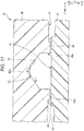
- the method includes introducing a part of a fused director to an inner side of the concave portion when viewed from a direction in which the first member and the second member are laminated, and fixing the first member and the second member by curing the fused director in a state where the concave portion is covered with the second surface and forming a flow path.
- air bubble dischargeability can be improved by suppressing the formation of the recess which causes the liquid to be stagnated between the director and the flow path, in the inner surface of the flow path formed by the concave portion and the second surface.
- the fused director flows with respect to a portion of which a cross-section has an acute angle, when viewed from a direction perpendicular to the lamination direction.
- the portion at which the angle is acute stagnation of the liquid likely occurs.
- the director by introducing the director to the portion of which the angle is acute, the formation of a portion of which the stagnation occurs can be suppressed.
- the concave portion has a shape in which a width of the cross-section becomes the largest at an opening portion, when viewed from a direction perpendicular to the lamination direction.
- the first member can be easily and inexpensively manufactured by molding the first member.
- a portion of which the first surface comes into contact with the second surface likely forms an acute angle, and the fused director is likely introduced to the portion of which the first surface comes into contact with the second surface due to capillary force.
- the concave portion has a vertex portion at a side opposite to the second member. According to the aspect, if the vertex portion is disposed so that the vertex portion is facing vertically upward, the air bubble dischargeability can be improved by collecting the air bubbles on the top.
- the director before being subjected to a fusion treatment is provided on the first member and has a wall surface which is flush with a wall surface defining the concave portion. According to the aspect, the distance between the director and the concave portion becomes smaller, and the fused director is likely to be introduced to the inner side of the concave portion.
- the director before being subjected to the fusion treatment is provided on the first member and has a shape in which the width of the director continues gradually decreasing from the first surface side toward the second surface side. According to the aspect, a load to bring the tip end surface of the director into contact with the second surface can be increased. Accordingly, the first member and the second member can be reliably fixed thereto.
- the fused director is cured into a concave curved surface shape which is obtained by connecting the second surface and the concave portion.
- an angle formed of the top surface of the director, and the inner surface of the concave portion and the second surface can be increased. Accordingly, the formation of the portion in which the flow of the liquid is stagnated can be suppressed.
- the second member includes a convex portion which is projected toward the first member side and in which a tip end surface is the second surface, and the width of the second surface is longer than a width of the director. According to the aspect, even when the first member and the second member are displaced in a width direction, the flow path can be reliably formed. In addition, the occurrence of variations in the fixing strength can be suppressed by suppressing the reduction of the welding area. Furthermore, by providing the second surface on only the tip end surface of the convex portion, surface accuracy of the second surface can be improved.
- a step portion is formed by the convex portion, and the fused director flows into the step portion. According to the aspect, by increasing the fusing area between the first member and the second member, the fixing strength between the first member and the second member can be improved.
- the thickness of the first member in the first surface is larger than a thickness of the second member in the second surface, and the transmittance of the second member with respect to an arbitrary wavelength is higher than a transmittance of the first member with respect to the same wavelength. According to the aspect, in a case where the director is fused with laser light, by reducing the thickness of the second member more than that of the first member, energy efficiency can be improved.
- a depth of the first member side of the flow path is larger than a depth of the second member side of the flow path. According to the aspect, by forming the deep flow path to the first member, a wasted region is reduced. Accordingly, the member can be efficiently used.
- inspecting a position of the director cured via the second member is further provided. According to the aspect, since an introducing position of the fused director can be inspected nondestructively, the reliability can be improved.
- the first member has a plurality of the concave portions
- the second member has a plurality of the convex portions which projects toward the first member side and in which the tip end surfaces are the second surfaces
- the adjacent convex portions are defined by the step portion that is a common recess. According to the aspect, since one step portion can define the plurality of second walls in common, the plurality of flow paths is easily provided.
- a flow path member including a flow path which is defined by a first wall defined by a first member in which a transmittance with respect to an arbitrary wavelength is a first value, a second wall defined by a second member in which the transmittance with respect to the same wavelength is a second value greater than the first value, and a third wall defined by a third member in which the transmittance with respect to the same wavelength is a third value between the first value and the second value, in which the third wall is disposed in an interface between the first wall and the second wall, and in which the third wall comes in contact with the first wall and the second wall respectively, at an angle larger than an angle of a portion of which the first wall virtually comes into contact with the second wall.
- the third wall which comes into contact with the interface between the first wall and the second wall at a relatively larger angle between the first wall and the second wall, the formation of the recess where the stagnation of the liquid occurs in the flow path is suppressed. Accordingly, the air bubble dischargeability can be improved.
- the third member since the third member is provided in the interface between the first wall and the second wall, the position of the third member can be confirmed nondestructively via the second member and the reliability can be improved.
- the width of the second wall is smaller than the width of the first wall. According to the aspect, since the third member occupies a range while the width of the second wall is smaller than the first wall, the third member is easily confirmed from the second member side.
- a width in the cross-section of the flow path defined by the first wall becomes the largest at an opening portion. According to the aspect, the first member can be easily and inexpensively manufactured by molding the first member.
- the flow path includes a vertex portion on a side facing the second member. According to the aspect, if the vertex portion is disposed so that the vertex portion is facing vertically upward, the air bubble dischargeability can be improved by collecting the air bubbles on the top surface.
- the third wall of the third member has a concave curved surface obtained by connecting the first wall and the second wall. According to the aspect, angles of the third wall and the first wall and the second wall can be increased. Accordingly, the formation of the portion in which the flow of the liquid is stagnated can be suppressed.
- the thickness of the first member is larger than the thickness of the second member. According to the aspect, in a case where the director is fused and cured with laser light to form the third member, by reducing the thickness of the second member more than that of the first member, energy efficiency can be improved.
- the depth of the first member side of the flow path is larger than the depth of the second member side on the flow path. According to the aspect, by forming the deep flow path to the first member, a wasted region is reduced. Accordingly, the member can be efficiently used.
- a liquid ejecting head including the flow path member according to the above aspect.
- the liquid ejecting head with improved reliability can be obtained by improving air bubble dischargeability.
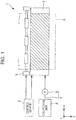
- Fig. 1 is a plan view showing an ink jet recording apparatus that is an example of a liquid ejecting apparatus according to Embodiment 1 of the invention.
- An ink jet recording apparatus 1 that is an example of the liquid ejecting apparatus according to the present embodiment is a so-called ink jet recording apparatus for printing only by transporting a recording sheet S that is an ejection medium such as paper or a resin sheet.
- a transporting direction of the recording sheet S is defined as a second direction Y, and in an in-plane direction of a landing surface of the recording sheet S on which an ink is landed, a direction perpendicular to the second direction Y is defined as a first direction X.
- a direction perpendicular to the both directions of the first direction X and the second direction Y is defined as a third direction Z.
- each of the directions (X, Y, and Z) is perpendicular to each other, as an example, but it is not limited thereto.
- the ink jet recording apparatus 1 is provided with an ink jet recording head 2 (hereinafter, simply referred to as the recording head 2) that is an example of the liquid ejecting head which ejects an ink as a liquid, a transporting mechanism 3 which transports the recording sheet S along the second direction Y, a feeder 4 which feeds the ink to the recording head 2, and a control device 5.
- the recording head 2 that is an example of the liquid ejecting head which ejects an ink as a liquid
- a transporting mechanism 3 which transports the recording sheet S along the second direction Y
- a feeder 4 which feeds the ink to the recording head 2
- a control device 5 a control device 5.
- the recording head 2 extends along the first direction X.
- the recording head 2 according to the present embodiment is provided with a plurality of main bodies which is arranged in a first direction X and ejects the ink and a flow path member which supplies the ink to each head main body, as will be described later in detail.
- the feeder 4 is provided with a reservoir 6 such as an ink cartridge or an ink tank in which the ink is stored, a supply pipe 7 such as a tube which is communicated with the reservoir 6 and the recording head 2, and a pump 8 that is a pumping unit which is provided on the way of the supply pipe 7 and pumps the ink in the reservoir 6 to the recording head 2.
- the ink in the reservoir 6 is pumped by the pump 8 and supplied to the recording head 2 via the supply pipe 7.
- the pumping unit is not particularly limited thereto, for example, the pumping unit may be a pushing unit which pushes the reservoir 6 from the outside.
- the pumping unit a pumping unit using a hydraulic head difference generated by adjusting a relative position between the recording head 2 and the reservoir 6 in a vertical direction may be used.
- the feeder 4 may be an ink cartridge which is directly mounted on the recording head 2 or the like.
- the transporting mechanism 3 transports the recording sheet S along the second direction Y, and in the present embodiment, the transporting mechanism 3 is provided with a driving unit (not shown) such as a driving motor which drives a transporting roller and the transporting mechanism 3. Also, the transporting mechanism 3 is not limited thereto, for example, the transporting mechanism 3 may be an endless belt rotated.
- the control device 5 performs overall control of the ink jet recording apparatus 1.
- the recording sheet S is transported by control of the transporting mechanism 3 based on a print signal from the outside and printing is performed by controlling the ejection of the ink droplet from the recording head 2.
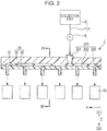
- Fig. 2 is a sectional view illustrating part of a flow path configuration of a recording head.
- each direction of the recording head 2 will be described based on directions when mounting on the ink jet recording apparatus 1, that is, the first direction X, the second direction Y, and the third direction Z.
- the recording head 2 is provided with a plurality of head main bodies 10 which ejects the ink and a flow path member 20 which feeds the ink fed from the feeder 4 to the head main body 10.
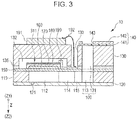
- Fig. 3 is a sectional view of the head main body according to the present embodiment of the invention.
- a flow path formed substrate 110 which configures the head main body 10 according to the present embodiment is formed of a silicon single-crystal substrate, on the one surface thereof, a vibrating plate 150 is formed.
- the vibrating plate 150 may be a single layer or a multiple layer selected from a silicon dioxide layer and a zirconium oxide layer.
- a plurality of pressure generation chambers 112 is arranged on the flow path formed substrate 110.
- a communicating unit 113 is formed, and the communicating unit 113 and each of the pressure generation chambers 112 are communicated with each other, via an ink supply path 114 and a communicating path 115 which are provided for each pressure generation chamber 112.
- the communicating unit 113 configures a part of a manifold 100 which is communicated with a manifold unit 131 of a protection substrate 130 to be described and is to be a common ink chamber of each pressure generation chamber 112.
- the ink supply path 114 is formed with a width narrower than the pressure generation chamber 112, and constantly maintains a flow path resistance of the ink which enters the pressure generation chamber 112 from the communicating unit 113.
- a nozzle plate 120 in one surface side of the flow path formed substrate 110 in the third direction Z, in a Z2 side that is the recording sheet S side, a nozzle plate 120, into which a nozzle opening 121 communicating with the vicinity of the end portion opposite to the ink supply path 114 of each pressure generation chamber 112 is drilled, is fixed with an adhesive, a heat weld film, or the like.
- the nozzle plate 120 for example, is formed from a glass ceramics, a silicon single crystal substrate, stainless steel, or the like.
- the vibrating plate 150 On the other hand, on the surface of the Z1 side which is the side opposite to the nozzle opening 121 of the flow path formed substrate 110 in the third direction Z, the vibrating plate 150 is formed. On the vibrating plate 150, a first electrode 160, a piezoelectric material layer 170, a second electrode 180 form a film and are laminated by a lithography method, and the laminate configures a piezoelectric actuator 311.
- the piezoelectric actuator 311 is a pressure generating unit which causes a change in pressure of the ink in the pressure generation chamber 112.
- the piezoelectric actuator 311 is also referred to as a piezoelectric element 311 and indicates a portion including the first electrode 160, the piezoelectric material layer 170, and the second electrode 180.
- it is configured such that any one of the electrodes of the piezoelectric actuator 311 is set as a common electrode, and the other electrode and the piezoelectric material layer 170 are patterned for each pressure generation chamber 112.
- the first electrode 160 is set as the common electrode of the piezoelectric actuator 311
- the second electrode 180 is set as an individual electrode of the piezoelectric actuator 311.
- the vibrating plate 150 and the first electrode 160 are operated as a vibrating plate. But it is not limited thereto. For example, only the first electrode 160 may be operated as the vibrating plate without the vibrating plate 150. In addition, the piezoelectric actuator 311 itself may function as the vibrating plate.
- each piezoelectric actuator 311 lead electrodes 190 are connected, respectively. A voltage is selectively applied to each piezoelectric actuator 311 via the lead electrode 190.
- a protection substrate 130 including the manifold unit 131 configuring at least a part of the manifold 100 is adhered via an adhesive 135.
- the manifold unit 131 is formed so as to extend in the width direction of the pressure generation chamber 112 through the protection substrate 130 in the third direction Z.
- the manifold unit 131 is communicated with the communicating unit 113 of the flow path formed substrate 110 to configure the manifold 100 that is an ink chamber common with each pressure generation chamber 112.
- a piezoelectric element holding portion 132 with a space at a level of not impeding the movement of the piezoelectric actuator 311 is provided.
- the piezoelectric element holding portion 132 may have a space at a level of not impeding the movement of the piezoelectric actuator 311. The space may be sealed, and may be unsealed.
- a protection substrate 130 As such a protection substrate 130, a material having a coefficient of thermal expansion almost the same as that of the flow path formed substrate 110 is preferably used, and in the present embodiment, the protection substrate 130 is formed using a silicon single crystal substrate having the same material as that of the flow path formed substrate 110.
- a through-hole 133 passing through the protection substrate 130 in the third direction Z is provided.
- the vicinity of the end portion of the lead electrode 190 drawn out of each piezoelectric actuator 311 is provided so as to be exposed into the through-hole 133.
- a driving circuit 191 for driving the piezoelectric actuator 311 is provided in the surface of the Z1 side of the protection substrate 130.
- the driving circuit 191 for example, a circuit substrate, or a semiconductor integrated circuit (IC), or the like can be used.
- the driving circuit 191 and the lead electrode 190 are electrically connected to each other via a connection wire 192 formed of an electrically conductive wire such as a bonding wire.
- a compliance plate 140 which is made of a sealing film 141 and a fixing plate 142 is adhered.
- the sealing film 141 is made of a material with low rigidity and with flexibility.
- One surface of the manifold unit 131 is sealed with the sealing film 141.
- the fixing plate 142 is formed by a relatively hard material. Since the region of the fixing plate 142 facing the manifold 100 becomes an opening 143 completely removed in a thickness direction, one surface of the manifold 100 is sealed with only the sealing film 141 with flexibility.
- the ink is removed from the feeder 4 shown in Fig. 1 via the flow path member 20, the inner portion from the manifold 100 to the nozzle opening 121 is filled with the ink, and then, a voltage is applied between the first electrode 160 and the second electrode 180 corresponding to the pressure generation chamber 112 according to the driving signal from the driving circuit 191.
- a voltage is applied between the first electrode 160 and the second electrode 180 corresponding to the pressure generation chamber 112 according to the driving signal from the driving circuit 191.
- a plurality of head main bodies 10 is connected to one flow path member 20, and in the present embodiment, six head main bodies 10 are connected thereto and configure the recording head 2.
- the arrangement direction of the head main bodies 10 with respect to the flow path member 20 is not particularly limited.
- the arrangement direction of the nozzle opening 121 is disposed in a direction inclined with respect to the second direction Y, that is, a direction intersecting the first direction X and the second direction Y, and the plurality of head main bodies 10 may be arranged in a linear shape along the first direction X.
- the nozzle opening 121 is disposed so as to coincide with the first direction X, and the plurality of the head main bodies 10 may be disposed in a zig-zag pattern along the first direction X.
- the description that the head main bodies 10 are disposed in a zig-zag pattern along the first direction X means that there are two or more rows of the head main bodies 10, in each of which the head main bodies 10 are arranged in the first direction.
- the head main body rows are arranged next to each other in the second direction Y and each head main body 10 is configured by a plurality of rows.
- the head main bodies 10 adjacent to each other in the first direction X are disposed such that a row of nozzle openings 121 of the head main body 10 in one head main body row overlaps with a row of nozzle openings 121 of the head main body in another head main body row in the second direction Y. Accordingly, a long nozzle opening 121 row can be formed across the first direction X by a plurality of the head main bodies 10.
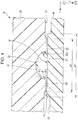
- Fig. 4 is a sectional view taken along the line IV-IV of Fig. 2 .
- the flow path member 20 is provided with a first member 30 and a second member 40.
- the flow path member 20 is configured such that the first member 30 and the second member 40 are laminated in the third direction Z. That is, in the present embodiment, the laminating direction of the first member 30 and the second member 40 is the third direction Z.
- the first member 30 side is defined as a Z1 side and the second member 40 side is defined as a Z2 side.
- the first member 30 and the second member 40 are formed of, for example, a resin material such as polypropylene. The details of the material will be described in below.
- the second member 40 is formed with a material having higher transmittance with respect to the wavelength of the laser light when welding, compared to the transmittance of the first member 30 with respect to the same wavelength.
- a flow path 200 is provided which is connected to one end portion of the supply pipe 7 (the other end of of the supply pipe 7 being connected to the reservoir 6) and which supplies the ink fed from the feeder 4 to the plurality of head main bodies 10.
- the flow path 200 is provided with a first flow path 201 which is provided on the first member 30 and is provided so as to allow the ink to flow along the third direction Z; a second flow path 202 which is communicated with the first flow path 201 and which is provided so as to allow the ink to flow along a direction perpendicular to the third direction Z, in the present embodiment, the first direction X; and a third flow path 203 which is communicated with the second flow path 202 and which is provided so as to allow the ink to flow along the third direction Z.
- the first flow path 201 is provided by passing through the first member 30 in the third direction Z, and in the opposite side to the end portion communicated with the second flow path 202 of the first flow path 201, the supply pipe 7 connected to the reservoir 6 is connected.
- the second flow path 202 is provided at an adhesion interface between the first member 30 and the second member 40, and is provided so as to allow the ink to flow along a direction perpendicular to the first flow path 201, that is, an in-plane direction including the first direction X and the second direction Y.
- the second flow path 202 is provided so as to allow the ink to flow along the first direction X.
- An opening to the second flow path 202 of the first flow path 201 is provided at a position inside the both end portion without the both end portion of the second flow path 202. That is, the first flow path 201 is not communicated with the end portion of the second flow path 202. It is not limited thereto.
- the first flow path 201 may be communicated with the end portion of the second flow path 202.
- the second flow path 202 will be described below in detail.
- the third flow path 203 is provided by passing through the second member 40 in the third direction Z.
- a plurality of the third flow paths 203 in the present embodiment six third flow paths 203, are provided by communicating with the second flow path 202.
- An end of each third flow path 203 is communicated with the second flow path 202, and the other end thereof is communicated with the head main body 10. Accordingly, the ink of the second flow path 202 is supplied to the plurality of head main bodies 10.
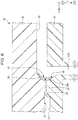
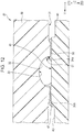
- the second flow path 202 configuring such a flow path 200 is formed such that a concave portion 32 provided on a first surface 31 that is a surface on the second member 40 side of the first member 30 is covered with a second surface 41 that is a surface on the first member 30 side of the second member 40.
- the second flow path 202 is formed by a first wall 33 defined by the first member 30, the second wall 41 defined by the second member 40, and a third wall 51 defined by a third member 50 which is provided on a boundary of the first wall 33 and the second wall 41.
- the first wall 33 is an inner surface of the concave portion 32 which opens the first surface 31 of the first member 30. It is preferable that such a concave portion 32 has a shape where the width thereof becomes the largest at the opening portion in a cross-section viewed from the direction perpendicular to the third direction Z that is a laminating direction of the first member 30 and the second member 40, that is, in the present embodiment, a cross-section extended in the second direction Y.
- the shape where the width of the cross section of the concave portion 32 becomes the largest at the opening portion means that in the cross-section, the width of the opening in the first surface 31 is provided while maintaining the same width or at a width decreasing (preferably continually and/or gradually) with increasing distance from the second surface 41, that is, toward the Z1 side in the third direction Z.
- the shape where the width of the cross-section of the concave portion 32 becomes the largest at the opening portion does not require a shape in which the width of the transverse section of the concave portion 32 continues gradually decreasing from the Z2 side toward the Z1 side.
- the shape where the width of the cross-section of the concave portion 32 becomes the largest at the opening portion includes a shape where the width of the transverse section of the concave portion 32 is maintained in the same width over the third direction Z, and a shape where the width is gradually decreasing from the Z2 toward the Z1.
- a shape of the transverse section of the concave portion 32 for example, a substantially semicircular shape, a substantially semi-ellipsoid shape, a substantially trapezoidal shape, a substantially triangle shape, and a substantially quadrilateral shape are included.
- the shape of the concave portion 32 is a shape where the width of the opening portion of the first surface 31 in the transverse section is the largest, the shape thereof is not limited to the above-mentioned shapes.
- a circular-shaped concave portion 32 with an angle of the transverse section of less than 180 degrees is formed.
- the angle of the first wall 33 that is an inner surface of the concave portion 32 and the first surface 31 can be equal to or less than 270 degrees. Accordingly, the first member 30 having the concave portion 32 can be easily and inexpensively manufactured by molding the first member 30.
- an angle of a portion of which the first wall 33 virtually comes into contact with the second surface 41 of the concave portion 32 can be decreased to equal to or less than 90 degrees.
- an angle of the portion of which the first wall 33 virtually comes into contact with the second surface 41 can be decreased to equal to or less than 90 degrees, and more preferably decreased at a sharp angle. Accordingly, by reducing the depth of the concave portion 32 in the third direction Z from the first surface 31, the flow rate of the ink which flows into the second flow path 202 can be increased.
- the concave portion 32 has a circular shape with an angle of the transverse section of less than 180 degrees (that is, the shape of less than half of a circle), the vertex portion is provided in the Z1 side in the third direction Z. Accordingly, when the Z1 side in the third direction Z is disposed upward in a vertical direction, the air bubbles are collected to the vertex portion of the concave portion 32 by buoyancy, and the air bubbles can be easily discharged.
- continuous directors 34 are provided over the range of the opening of the concave portion 32 of the first surface 31.
- the directors 34 may also be termed rails or guides.
- the directors 34 are provided so as to protrude from the first surface 31 toward the second member 40 side.
- the directors 34 are provided integrally continuous from the first member 30.
- the director 34 includes a wall surface 34a which is flush with the first wall 33 that is an inner surface of the concave portion 32. Accordingly, a part of the director 34 can be reliably introduced into an inner side of the concave portion 32 by subjecting a part of the director 34 to the fusing treatment.
- the wall surface 34a of the director 34 is provided along a normal direction with respect to the first surface 31, that is, along the third direction Z. Accordingly, an angle of the portion in which the director 34a comes into contact with the second surface 41 is 90 degrees.
- the wall surface 34a also may be formed into an inclined surface which is inclined such that the opening side is extended with respect to the second surface 41.
- the wall surface 34a may be formed in a curved surface, in particular, a concave curved surface.
- the wall surface 34a of the director 34 may be provided so as to protrude inside the concave portion 32.
- the first member 30 which integrally has the directors 34 can be formed by molding the first member 30. That is, by providing the wall surface 34a of the director 34 at the same position as that of the opening edge portion of the first surface 31 side of the concave portion 32 or providing the wall surface 34a so as to be inclined such that the opening is extended outside the position, the first member 30 can be inexpensively manufactured with high accuracy by molding the first member 30.
- the second surface 41 and the wall surface 34a can be disposed at an angle of 90 degrees or less. Accordingly, the fused director 34 can easily feed into the corner portion of the wall surface 34a of the director 34 and the second surface 41 by capillary force.
- the second member 40 includes a second surface 41 on the first member 30 side.
- the second member 40 includes a convex portion 42 which projects to the first member 30 side, that is, the Z1 side, and the tip end surface of the convex portion 42 is the second surface 41. That is, the second surface 41 is defined by the convex portion 42.
- the convex portion 42 is defined by a step portion 43 that is a concave portion provided on the outside thereof.
- the second surface 41 provided on the tip end of the convex portion 42 is a flat surface in which a direction including the first direction X and the second direction Y is set as an in-plane direction.
- a second wall of the second member 40 defining the second flow path 202 means the second surface 41 (hereinafter, also referred to as a second wall 41).
- a width w1 of the second surface 41 is larger than a width w2 of the director 34, as will be described later in detail. That is, it is preferable that the width w1 of the second surface 41 in the second direction Y is larger than the width w2 including the concave portion 32 and the director 34 provided on both sides of the concave portion 32. Accordingly, it is possible to suppress weld defects caused by the positional deviation, and to suppress the reduction in the welded region caused by the positional deviation. Therefore, it is possible to firmly fix the first member 30 and the second member 40.
- the first member 30 and the second member 40 are welded to each other by fusing a part of the director 34 in a state where the tip end surface of the director 34 of the first member 30 comes into contact with the second surface 41 of the second member 40, as will be described later in detail.
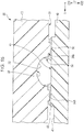
- the third member 50 is formed such that the part of the director 34 and the part of the second member 40 are melted, fed inside the concave portion 32, and cured. That is, the third member 50 includes materials both of the first member 30 and the second member 40.
- the third member 50 is formed by welding the director 34 which contacted with the second surface 41 and curing the fused director 34, mainly, the third member 50 is formed such that a part of the fused director 34 is mixed with a part of the second member 40 fused at the same time period of fusing the director 34. That is, the third member 50 is made of a material in which the transmittance with respect to the arbitrary wavelength, in the present embodiment, a wavelength of the fusing laser light is higher than that of the first member 30, and lower than that of the second member 40.
- the second flow path 202 is defined by the first wall 33 of the first member 30 in which the transmittance with respect to the arbitrary wavelength is a first value, the second wall 41 of the second member 40 having a higher transmittance than the first value, and the third wall 51 which is formed by the third member 50 having a third value between the first value and the second value.
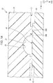
- the director 34 By subjecting the director 34 to the fusing treatment in a state where the director 34 comes into contact with the second surface 41, the third member 50 is formed in a region where the director 34 and the second surface 41 face each other in the third direction Z.
- a part of the fused director 34 inside the concave portion 32 is introduced to an interface portion between the first wall 33 of the concave portion 32 and the second wall 41 and cured.
- the third member 50 is provided inside the concave portion 32 in plan view from the third direction Z that is a lamination direction between the first member 30 and the second member 40.
- a shape where a part of the proximal end portion side of the director 34 is remained is obtained.
- a shape where the director 34 is entirely fused and a part thereof does not remain may be used.
- the shape where the width of the cross section of the concave portion 32 becomes the largest at the opening portion as described above is used.
- an angle at which the first wall 33 of the concave portion 32 comes into contact with the second surface 41 and the second member 40 can be easily to 90 degrees or less.
- the fused director 34 can easily feed into the corner portion of the first wall 33 of the concave portion 32 and the second surface 41 by capillary force and can form the third member 50.
- an angle at which the first wall 33 of the concave portion 32 comes into contact with the second surface 41 can easily be the acute angle.
- the third member 50 formed inside the concave portion 32 is provided in the interface portion between the first wall 33 and the second wall 41 which are inner surfaces of the concave portion 32 across the first wall 33 and the second wall 41.
- the interface portion between the first wall 33 and the second wall 41 means a portion of which the first wall 33 directly or indirectly continues with the second wall 41.
- the first wall 33 and the second wall 41 are continuously connected via the wall surface 34a of the director 34, the first wall 33 and the second wall 41 are not directly continuously connected. Also by entirely fusing the director 34, the first wall 33 and the second wall 41 are directly continuously connected.
- the surface connecting the first wall 33 of the third member 50 and the second wall 41 becomes the third wall 51.
- the third wall 51 of the third member 50 comes into contact with the first wall 33 and the second wall 41 at an angle larger than an angle ⁇ 1 of a portion of which the first wall 33 virtually comes into contact with the second wall 41. That is, in the present embodiment, an angle ⁇ 2 at which the third wall 51 comes into contact with the first wall 33 and the angle ⁇ 3 at which the third wall 51 comes into contact with the second wall 41 are angles larger than the angle ⁇ 1 of a portion of which the first wall 33 virtually comes into contact with the second wall 41.
- the angle ⁇ 1 of a portion of which the first wall 33 virtually comes into contact with the second wall 41 means that in the present embodiment, since the first wall 33 does not directly come into contact with the second wall 41, an angle of the portion of which the first wall 33 is virtually extended and comes into contact with the second wall 41. Also in a case where the director 34 is entirely fused, since the first wall 33 comes into contact with the second wall 41, an angle ⁇ 1 of a portion where the first wall 33 virtually comes into contact with the second wall 41 includes an angle of a portion of which the first wall 33 comes into contact with the second wall 41.
- the transverse section of the concave portion 32 is provided into a circular-shaped concave having an angle less than 180 degrees, and thus the angle ⁇ 1 where a portion of the first wall 33 virtually comes into contact with the second wall 41 becomes an acute angle.
- Fig. 4 the angle is measured at a position in-line with the first surface 31, which marks the boundary between the wall surface 34a of the director 34 and the first wall 33 of the concave portion 32.
- the third wall 51 has a concave curved surface obtained by connecting the first wall 33 and the second wall 41.
- the description that the third wall 51 has the concave curved surface means a shape having centers of curvature on the second flow path 202 side in relation to the third member 50.
- the third wall 51 may be a flat surface.
- the third wall 51 that is a surface thereof likely becomes the concave curved surface. It is preferable that the third wall 51 becomes the flat surface or the concave curved surface as described above. Accordingly, as compared to a case where the third wall 51 is formed into a convex curbed surface, the third wall 51 can come into contact with the first wall 33 and the second wall 41, respectively, at the angles ⁇ 2 and ⁇ 3 larger than the angle ⁇ 1 of a portion of which the first wall 33 virtually comes into contact with the second wall 41.
- the second flow path 202 is defined by the first wall 33 of the first member 30, the second wall 41 of the second member 40, and the third wall 51 of the third member 50.
- the thickness of the first member 30 from the first surface 31 in the third direction Z (that is, the thickness of the first member 30 excluding the director 34) is larger than the thickness of the second member 40 from the second surface 41 (that is, the thickness of the second member 40 including the convex portion 42). According to this, it is possible to improve the energy efficiency when the director 34 is subjected to the fusing treatment with laser light which has passed through the second member 40.
- the depth of the first member 30 side of the second flow path 202 in the third direction Z with respect to the interface between the first surface 31 and the second surface 41 is greater than the second member 40 side of the second flow path 202. That is, in Embodiment 1 described above, since the concave portion 32 is formed on the first member 30, and the second surface 41 that is the flat surface is provided on the second member 40, the depth of the second flow path 202 of the first member 30 means the depth of the concave portion 32 and the depth of the second flow path 202 of the second member 40 becomes zero (0). In this manner, by forming the second flow path 202 in the first member 30 deeper than in the second member 40, the first member 30 and the second member 40 can be efficiently used.
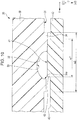
- Fig. 5 is a sectional view of part of the flow path member to be compared.
- a director 334 provided on a first member 330 of a flow path member 320 to be compared is provided on a position apart from the outside the opening of a concave portion 332 in a first surface 331.
- a director 334 By subjecting the director 334 to the fusing treatment in a state where the director 334 comes into contact with a second surface 341 of a second member 340, a space formed by the first surface 331, a wall surface 334a of the director 334, and the second surface 341 is filled with a part of the fused director 334, and cured. Accordingly, a third wall 351 of the third member 350 formed by the director 334 fused is provided coming into contact with the first surface 331 and not a first wall 333.
- the third member 350 is provided inside the concave portion 332 on plan view from the third direction Z. That is, in the comparative example in Fig. 5 , a space formed by the wall surface 334a of the director 334 in which the third member 350 is provided, the first surface 331, and the second surface 341 is not included in the concave portion 332. Due to the size of the space, in contrast with the invention of this specification, it cannot be considered that the third wall 351 comes into contact with the first wall 333 that is an inner side of the concave portion 332.
- the description that the third wall 51 comes into contact with the first wall 33 and the second wall 41 means that the third wall 51 directly comes into contact with the first wall 33 and the second wall 41.
- a recess 300 which is formed by the first wall 333, the first surface 331, the second surface 341, and the third wall 351 is formed.
- the recess 300 since the ink flow is stagnated, the air bubbles are retained in the recess 300, the retained air bubbles are grown, and grown air bubbles are introduced to the head main body 10 at unexpected timing. Therefore, ink ejection failure occurs.
- the third member 50 is provided inside the concave portion 32 in plan view from the third direction Z.
- the third wall 51 comes into contact with the first wall 33 and the second wall 41, respectively, at the angles ⁇ 2 and ⁇ 3 larger than the angle ⁇ 1 at which a portion of the first wall 33 virtually comes into contact with the second wall 41. Accordingly, it is possible to suppress the formation of the recess 300 on the wall surface of the second flow path 202. That is, by introducing the fused director 34 inside the concave portion 32, a portion of the ink flow of the second flow path 202 (concave portion 32) is reduced by the fused director 34. It is possible to suppress the problems caused by recess 300 such as ink ejection failure, increases in pressure loss, and generating the air bubbles from the nozzle opening 121.
- the director 34 it is possible to form the director 34 such that the width of the director 34 in the second direction Y is larger than that of the director 334 shown in Fig. 5 . That is, in a case where the director 334 shown in Fig. 5 is formed at the same width as that of the director 34 shown in Fig. 4 , since it is necessary to form the director 334 in a position apart from the concave portion 332, the size of the flow path member 20 becomes larger. Therefore, it is required to reduce the width of the director 334 as compared to the width of the director 34. By reducing the width of the director 334, the welding strength between the first member 330 and the second member 340 becomes deteriorated.
- the director 34 having a larger width can be formed without increasing the size of the flow path member 20 compared to the director 334.
- the fused director 34 is introduced outside the unfused director 34-that is, away from the concave portion 32 in the Y direction - in the same manner as the side facing the concave portion 32 and is cured. That is, the third member 50 welding the first member 30 and the second member 40 extends from the portion at which the director 34 relatively faces the second surface 41 to the inside and the outside the concave portion 32. Accordingly, by increasing the welding area between the first member 30 and the second member 40, the two can be firmly fixed.
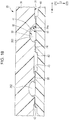
- Fig. 6 is an enlarged sectional view of a part of Fig. 3 .
- a height of the concave portion 32 of the first member 30 in the third direction Z continues gradually decreasing toward the end portion in the first direction X, that is, a direction of the ink flow.
- the third flow path 203 of the second member 40 includes a tapered surface 44 inclined such that the width of the opening increases toward the first wall 33.
- the third member 50 is formed in the interface portion between the first wall of the concave portion 32 and the tapered surface 44 of the second member 40 across the first wall 33 and the tapered surface 44. That is, the third wall 51 of the third member 50 is provided such that the first wall 33 is continuous with the tapered surface 44.
- Such a third wall 51 is formed and serves as the concave curved surface.
- the tapered surface 44 is formed in the third flow path 203, and the third member 50 is provided in the corner portion formed by the tapered surface 44 and the first wall 33, thereby it is possible to suppress the portion of which the ink is stagnated, in a portion of which the ink flow between the second flow path 202 and the third flow path 203 is changed.
- such a flow path member 20 by using materials such that the second member 40 has a higher transmittance with respect to an arbitrary wavelength of light (for example, the wavelength of visible light) than the transmittance of the first member 30 with respect to light having the same wavelength, it is possible to confirm the welding portion from the second member 40, that is, the third member 50, by visual recognition.
- the transmittance of the third member 50 formed by welding is higher than that of the first member 30 and is lower than that of the second member 40, the third member 50 can be easily recognized by visual recognition via the second member 40. Accordingly, the welding state of the flow path member 20 can be easily confirmed, and the flow path member 20 with high reliability can be obtained while suppressing the leakage of the ink from the welding surface and the decrease in the welding strength.
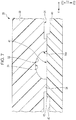
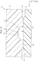
- Figs. 7 and 8 are sectional views illustrating part of the method of manufacturing the flow path member
- Fig. 9 is a bottom view of the flow path member from the second member side.
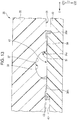
- the unfused director 34 of the first member 30 comes into contact with the second surface 41 of the second member 40.
- the concave portion 32 which opens to the first surface 31 that is a surface on the Z2 side is provided on the first member 30. It is preferable that the concave portion 32 has a shape where the width thereof becomes the largest at the opening portion in a cross-section viewed from the direction perpendicular to the third direction Z that is a laminating direction of the first member 30 and the second member 40, that is, in the present embodiment, a cross-section extended in the second direction Y.
- the shape where the width of the cross section of the concave portion 32 becomes the largest at the opening portion means that in the cross-section, the width of the opening in the first surface 31 is provided while maintaining the same width or at a width that continues gradually decreasing with increasing distance away from the second surface 41, that is, toward the Z1 side in the third direction Z.
- the shape where the width of the cross-section of the concave portion 32 becomes the largest at the opening portion includes a shape where the width of the transverse section of the concave portion 32 does not continue gradually decreasing from the Z2 toward the Z1.
- the shape where the width of the cross-section of the concave portion 32 becomes the largest at the opening portion includes a shape where the width of the transverse section of the concave portion 32 is maintained in the same width over the third direction Z, and a shape where the width is gradually decreasing from the Z2 toward the Z1.
- a shape of the transverse section of the concave portion 32 for example, a substantially semicircular shape, a substantially semi-ellipsoid shape, a substantially trapezoidal shape, a substantially triangle shape, and a substantially quadrilateral shape are included.
- the shape of the concave portion 32 is a shape where the width of the opening portion of the first surface 31 in the transverse section is the largest
- the shape thereof is not limited to the above-mentioned shapes.
- a circular-shaped concave portion 32 with an angle of the transverse section of less than 180 degrees is formed.
- the shape is less than a half circle.
- the angle of the first wall 33 that is an inner surface of the concave portion 32 and the first surface 31 can be equal to or less than 270 degrees. Accordingly, the first member 30 having the concave portion 32 can be easily and inexpensively manufactured by molding the first member 30.
- the continuous directors 34 are provided over the range of the opening of the concave portion 32 of the first surface 31.
- the directors 34 are provided so as to protrude from the first surface 31 toward the Z2 side.
- the directors 34 according to the present embodiment are provided integrally continuous with the first member 30.
- the director 34 includes the wall surface 34a which is flush with the first surface 31 of the concave portion 32.
- the wall surface 34a of the director 34 is provided along a normal direction with respect to the first surface 31, that is, along the third direction Z. Accordingly, an angle of the portion in which the director 34a comes into contact with the second surface 41 is 90 degrees.
- the wall surface 34a also may be formed into an inclined surface which is inclined such that the opening side is extended with respect to the second surface 41.
- the wall surface 34a may be formed in a curved surface, in particular, a concave curved surface.
- the wall surface 34a of the director 34 may be provided so as to protrude inside the concave portion 32.
- the first member 30 which integrally has the directors 34 cannot then easily be formed by molding the first member 30.
- the first member 30 can be inexpensively manufactured with high accuracy by molding the first member 30.
- the wall surface 34a of the director 34 at the same position as that of the opening edge portion of the first surface 31 side of the concave portion 32 or providing the wall surface 34a so as to be inclined such that the opening is extended outside the position, when the director 34 comes into contact with the second surface 41, the second surface 41 and the wall surface 34a can be disposed at an angle of 90 degrees or less. Accordingly, in the subsequent process, the fused director 34 can easily feed into the corner portion of the wall surface 34a of the director 34 and the second surface 41 by capillary force.
- the second member 40 includes the second surface 41 with which the above-described director 34 comes into contact.
- the second surface according to the present embodiment is provided in a tip end surface of the convex portion 42 projecting to the first member 30 side.
- the second surface 41 provided on the tip end of the convex portion 42 is a flat surface in which a direction including the first direction X and the second direction Y is set as an in-plane direction.
- a width w1 of the second surface 41 is larger than a width w2 of the directors 34 across the concave portion 32, as will be described later in detail. That is, it is preferable that the width w1 of the second surface 41 in the second direction Y is larger than the width w2 including the concave portion 32 and the directors 34 provided on both sides of the concave portion 32.
- a width w1 of the second surface 41 in the second direction Y is larger than the width w2 including the concave portion 32 and the directors 34 provided on both sides of the concave portion 32.
- the directors 34 and the second surface 41 can reliably be constantly welded with the constant area in the subsequent process, and it is possible to suppress the occurrence of the variations in the welding strength. Therefore, it is possible to suppress the ink leakage from the welding portion or the breakage due to the shortage in the welding strength.
- first member 30 and the second member 40 configuring the flow path member 20 are formed of, for example, a resin material such as polypropylene.
- the transmittance of the second member 40 with respect to the arbitrary wavelength is set to be larger than the transmittance of the first member 30 with respect to the same wavelength.
- the arbitrary wavelength is a wavelength of the visible light.
- the arbitrary wavelength is not limited to the wavelength of the visible light, for example, in a case where the inspection process is performed by an infrared camera, the arbitrary wavelength is a wavelength of an infrared light beam.
- a material which has relatively high transmittance with respect to the arbitrary wavelength may be used in the both first member 30 and the second member 40. According to this, the welding portion can be confirmed from the both sides in the third direction Z, and the inspection process can be reliably performed.
- the material having relatively high transmittance with respect to the arbitrary wavelength is used for the both the first member 30 and the second member 40, since the laser light passes the both the first member 30 and the second member 40, the welding with the laser light cannot be efficiently performed. Therefore, in a case where the material having relatively high transmittance with respect to the arbitrary wavelength is used for the both the first member 30 and the second member 40, for example, welding of the first member 30 and the second member 40 may be performed by ultrasonic welding or the like. In a case where the first member 30 and the second member 40 are welded by the ultrasonic welding without the inspection process, a material having the relatively low transmittance with respect to the arbitrary wavelength can be commonly used for the first member 30 and the second member 40.
- the arbitrary wavelength defining the transmittance is a wavelength of the laser light. That is, when the transmittance of the second member 40 with respect to the laser light increases compared to the transmittance of the first member 30, the director 34 is efficiently subjected to the fusing treatment by irradiating the second member 40 side with the laser light and by irradiating the director 34 of the first member 30 with the laser light which has passed through the second member 40.
- the thickness of the first member 30 up to the first surface 31 in the third direction Z is larger than the thickness of the second member 40 up to second surface 41. According to this, it is possible to improve the energy efficiency when the director 34 is subjected to the fusing treatment with laser light which has passed through the second member 40.
- the depth of the first member 30 side of the second flow path 202 in the third direction Z from the interface between the first surface 31 and the second surface 41 is greater than that of the second member 40 side of the second flow path 202. That is, in the present embodiment described above, since the concave portion 32 is formed on the first member 30, and the second surface 41 that is the flat surface is provided on the second member 40, the depth of the second flow path 202 of the first member 30 corresponds to the depth of the concave portion 32 and the depth of the second flow path 202 of the second member 40 becomes zero (0). In this manner, by forming the second flow path 202 on the first member 30 deeper than the second member 40, the first member 30 and the second member 40 can be efficiently used.
- the wavelength of the laser light to be used in the subsequent process includes a range of the visible light wavelength. Therefore, in the flow path member 20 according to the present embodiment, the welding portion can be inspected in the visual manner from the second member 40 side, even in the next inspection process.
- the director 34 of the first member 30 is subjected to the fusing treatment and a part of the fused director 34 is formed inside the concave portion 32 in plan view from the third direction Z that is a laminating direction of the first member 30 and the second member 40.
- the director 34 of the first member 30 is subjected to the fusing treatment and a part of the fused director 34 is formed inside the concave portion 32 in plan view from the third direction Z that is a laminating direction of the first member 30 and the second member 40.
- the first member 30 comes into contact with the second member 40 by applying the pressure.
- the fused director 34 is introduced into the concave portion 32 from between the director 34 and the second surface 41.
- the director 34 since the director 34 includes the director wall surface 34a which is flush with the first wall 33 that is an inner surface of the concave portion 32, by subjecting a part of the director 34 to the fusing treatment, the part of the director 34 can be reliably introduced to the inside the concave portion 32.
- the fused director 34 is introduced also outside that is a side opposite to the concave portion 32 of the director 34.
- the angle of the wall surface 34a of the director 34 and the second surface 41 is set as 90 degrees or less, the fused director 34 which is introduced into the concave portion 32 can be fed extending the corner portion by capillary force.
- the fused director 34 in the concave portion 32 is introduced to the interface portion between the first wall 33 and the second surface 41 so as to extend over the first wall 33 and the second wall 41. That is, if the introducing amount of the fused director 34 is small, the director 34 is introduced to only the corner portion between the wall surface 34a of the director 34 and the second surface 41.
- the director 34 can be introduced so as to spread over the first wall 33 and the second wall 41.
- the introducing amount of the fused director 34 can be adjusted by, for example, the pressure pushing the director 34 to the second surface 41, and an amount required for fusing treatment of the director 34, that is, output of the laser light 400, or the like.
- the interface portion between the first wall 33 and the second wall 41 means a portion of which the first wall 33 directly or indirectly continues with the second wall 41.
- the director 34 since the director 34 is not entirely fused, and only a part of the tip end side is fused, the first wall 33 continues with the second wall 41 via the wall surface 34a of the director 34. Accordingly, the first wall 33 does not continue with the second wall 41 in a state where the first wall 33 directly comes into contact with the second surface 41.
- the director 34 is entirely fused
- the first wall 33 can be continued with the second wall 41 in a state where the first wall 33 directly comes into contact with the second surface 41.
- the third member 50 formed by subjecting the director 34 to the fusing treatment and curing the fused director 34 in the subsequent process mainly includes the material forming the director 34 and the material forming the second member 40.
- the transmittance with respect to the laser light 400 of the first member 30 is low, and the transmittance with respect to the laser light 400 of the second member 40 is higher than that of the first member 30, the transmittance with respect to the laser light 400 of the third member 50, which is formed by subjecting the director 34 to the fusing treatment and curing the fused director 34 in the subsequent process, is higher than that of the first member 30 and lower than that of the second member 40.
- the director 34 only the tip end portion which comes into contact with the second member 40 is subjected to the fusing treatment, and remained in the proximal end portion side, but it is not limited thereto.
- the director 34 may be entirely fused. In a case where the director 34 is entirely fused, the shape where the width of the cross section of the concave portion 32 becomes the largest at the opening portion, and the angle at which the first wall 33 that is an inner surface of the concave portion 32 comes into contact with the second surface 41 of the second member 40 can be set to 90 degrees or less.
- the fused director 34 can easily feed into the corner portion of the first wall 33 of the concave portion 32 and the second surface 41 by capillary force.
- the first member 30 having the concave portion 32 can be easily and inexpensively manufactured by molding the first member 30.
- the angle at which the first wall 33 of the concave portion 32 comes into contact with the second surface 41 can set to an acute angle.
- the first member 30 is fixed, that is, welded with the second member 40.
- the third member 50 is formed by curing the fused director 34.
- the fused director 34 may be cured by being placed at a normal temperature (room temperature) and may also be cured by cooling to a temperature lower than the room temperature.
- the third member 50 formed by curing the fused director 34 is provided in the interface portion between the first wall 33 and the second surface 41 which are inner surfaces of the concave portion 32 across the first wall 33 and the second surface 41 (second wall 41) as described above.
- the surface connecting the first wall 33 of the third member 50 and the second wall 41 becomes the third wall 51.
- the third wall 51 of the third member 50 comes into contact with the first wall 33 and the second wall 41 at an angle larger than an angle ⁇ 1 of a portion at which the first wall 33 virtually comes into contact with the second wall 41. That is, in the present embodiment, the angle ⁇ 2 of a portion at which the third wall 51 comes into contact with the first wall 33 and angle ⁇ 3 of a portion at which the third wall 51 comes into contact with the second wall 41 are an angle larger than the angle ⁇ 1 at a portion of which the first wall 33 virtually comes into contact with the second surface 41.
- the angle ⁇ 1 at a portion of which the first wall 33 virtually comes into contact with the second wall 41 means in the present embodiment, since the first wall 33 does not directly come into contact with the second wall 41, an angle of the portion at which the first wall 33 is virtually extended and comes into contact with the second wall 41.
- this can also be considered as the angle between the bottom of the first wall 33 and a plane parallel to the second wall 41.
- an angle ⁇ 1 of a portion at which the first wall 33 virtually comes into contact with the second wall 41 includes an angle of a portion at which the first wall 33 comes into contact with the second wall 41.
- the transverse section of the concave portion 32 is provided into a circular-shaped concave having an angle less than 180 degrees, so the angle ⁇ 1 of a portion at which the first wall 33 virtually comes into contact with the second wall 41 becomes an acute angle.
- the wall surface 34a of the director 34 at the same position as that of the opening edge portion of the first surface 31 side of the concave portion 32 or providing it so as to be inclined outside the position thereof, an angle of the portion at which the wall surface 34a of the director 34 comes into contact with the second surface 41 is set to an angle of 90 degrees or less.
- the third wall 51 has a concave curved surface obtained by connecting the first wall 33 and the second wall 41.
- the description that the third wall 51 has the concave curved surface means a shape having centers of curvature on the second flow path 202 side in relation to the third member 50.
- the third wall 51 may be a flat surface.
- the third wall 51 can come into contact with the first wall 33 and the second wall 41, respectively, at the angles ⁇ 2 and ⁇ 3 larger than the angle ⁇ 1 of a portion at which the first wall 33 virtually comes into contact with the second wall 41.
- the flow path member 20 having the second flow path 202 is formed by the first wall 33 of the first member 30, the second wall 41 of the second member 40, and the third wall 51 of the third member 50 which are formed as described above.
- the third member 50 is formed by introducing the fused director 34 into the concave portion 32 and curing the introduced director. Accordingly, it is possible to easily reduce a portion at which the ink flow of the second flow path 202 is stagnated. Therefore, it is possible to simplify the manufacturing process. By reducing the portion at which the ink flow of the second flow path 202 is stagnated, the retaining of the air bubbles in the portion at which the ink is stagnated is reduced. Accordingly, it is possible to improve the air bubble dischargeability.
- the welding portion that is, the third member 50 can be confirmed nondestructively in a visual manner or by a camera.
- the width of the second wall 41 in the flow path 202 is smaller than the first wall 33 and thereby prevents the third wall 51 which comes into contact which the second wall 41 being misidentified as the first wall 33.
- the third member 50 occupies a range while the width of the second wall 41 is smaller than the first wall 33, the third member 50 is easily confirmed from the second member 40 side.
- the transmittance of the third member 50 formed by welding is higher than that of the first member 30, and lower than that of the second member 40, the third member 50 is easily confirmed via the second member 40. Accordingly, the introducing amount of the third member 50 to the concave portion 32 or the introducing amount of third member 50 to the outside the concave portion 32 can be confirmed nondestructively. The determination of the defective product can be easily performed, and it is possible to improve the reliability of the flow path member 20.
- Figs. 11 and 12 are sectional views illustrating a method of manufacturing a flow path member according to Embodiment 2 of the invention.
- the members that are the same as the above-described present embodiment are denoted by the same reference numerals, and are not described again here.
- a director 34A of the first member 30 comes into contact with the second surface 41 of the second member 40.
- the directors 34A before being subjected to the fusing treatment are provided over the range of the opening of the concave portion 32.
- the directors 34A are provided so as to protrude from the first surface 31 toward the Z2 side.
- the director 34A has a shape in which the width of the director in the second direction Y continues gradually decreasing from the first surface 31 toward the second surface 41.
- the director 34A has the wall surface 34a which is flush with a first wall 33 that is an inner surface of the concave portion 32.
- the wall surface 34a is provided along the third direction Z, that is, a normal direction with respect to the first surface 31. Accordingly, the director 34A becomes an inclined surface in which the side facing the director 34A is inclined.
- the first member 30 is welded to the second member 40 and a part of the cured director 34A can be introduced into the concave portion 32.
- the first member 30 is fixed to the second member 40.
- the width of the director 34A decreasing toward the second member 40 side in such a manner, a load when the tip end surface of the director 34A comes into contact with the second surface 41 is easily concentrated and the director 34A can be reliably contacted to the second surface 41. Therefore, the first member 30 can be firmly fixed to the second member 40 by the fused director 34A.
- the shape is set as a shape in which the width of the director 34A continues gradually decreasing toward the second member 40.
- the shape is not limited thereto. For example, when welding the first member 30 and the second member 40, the portion of which the width of the director 34A continues gradually decreasing toward the second member 40 is fused and may be destroyed.
- Fig. 13 is a sectional view illustrating a part of a flow path member according to Embodiment 3 of the invention.
- the members that are the same as the above-described present embodiment are denoted by the same reference numerals, and are not described again here.
- the fused director 34 is introduced into the step portion 43, and the director 34 causes the second member 40 to weld with the first member 30, even in the step portion 43.
- the welding area between the first member 30 and the second member 40 increases. Accordingly, the two are firmly fixed to each other.
- the third member 50 is provided continuously from the second surface 41 into the step portion 43. Therefore, the third members 50 are also provided on the step portion between the convex portion 42 and the step portion 43. Accordingly, it is possible to improve the fixing strength between the first member 30 and the second member 40 by the anchor effect.
- Figs. 14 and 15 are sectional view illustrating a method of manufacturing a flow path member according to Embodiment 4 of the invention.
- the members that are the same as the above-described present embodiment are denoted by the same reference numerals, and are not described again here.
- a director 34B of the first member 30 comes into contact with the second surface 41 of the second member 40.
- the director 34B has the wall surface 34b outside the first wall 33 that is an inner surface of the concave portion 32.
- the wall surface 34b is provided along the third direction Z, that is, a normal direction with respect to the first surface 31. That is, between the first member 30 and the second member 40, a space is formed by the first surface 31, the second surface 41, and the wall surface 34b of the director 34B.
- the director 34B is subjected to the fusing treatment, and is introduced into the concave portion 32.
- the space formed by the first surface 31, the second surface 41, and the wall surface 34b of the director 34B is filled with the fused director 34B, and the director 34B is further introduced inside the concave portion 32.
- the first member 30 is fixed to the second member 40.
- the third member 50 including the third wall 51 same as Embodiment 1 described above can be formed.
- Fig. 16 is a sectional view illustrating part of a flow path member according to Embodiment 5 of the invention.
- the members that are the same as the above-described present embodiment are denoted by the same reference numerals, and are not described again here.
- a second-member-side concave portion 45 is provided in the second surface 41 of the second member 40 which configures the flow path member 20 according to the present embodiment.
- the second-member-side concave portion 45 has a shape in which the width of the cross-section is the largest at the opening portion.
- a shape in which the width of the cross-section continues gradually decreasing from the Z1 side toward the Z2 side is prepared. Accordingly, the transverse section of the second flow path 202 can be set as a generally circular shape and a portion of which the ink flown to the second flow path 202 is stagnated can be reduced.
- the second-member-side concave portion 45 is formed such that the width of the opening of the first member 30 side is larger than that of the opening at the second member 40 side of the concave portion 32 of the first member 30. Accordingly, even when the first member 30 and the second member 40 are displaced in a width direction of the transverse surface of the second flow path 202, it is suppressed that the second-member-side concave portion 45 is partially covered with the director 34. Accordingly, it is possible to stabilize the shape of the second flow path 202.
- the width of the opening of the second-member-side concave portion 45 is smaller than the width of the concave portion 32 of the first member 30, a corner portion is formed in a portion at which the first wall 33 of the concave portion 32 or the wall surface 34a of the director 34 comes into contact with the second surface 41.
- the third member 50 including the third wall 51 same as Embodiment 1 described above at the corner portion the second flow path 202 can be further closer to a circle by the first wall 33, the second wall 41, and the third wall 51, and it is possible to improve the air bubble dischargeability.
- the fused directors 34, 34A, and 34B are provided only in the interface portion between the first wall 33 and the second wall 41, but it is not particularly limited thereto.
- the directors may be introduced in a portion having an acute angle other than the interface between the first wall 33 and the second wall 41 and then may be cured. That is, as shown in Fig. 17 , in a case where a corner portion in which the vertex portion of the concave portion 32 of the first member 30 has an acute angle, the directors 34, 34A, and 34B fused are introduced into the vertex portion to form a third member 50A.
- the location is not particularly limited thereto.
- FIG. 18 an example of the configuration, in which one second flow path 202 is provided on the flow path member 20, is described.
- Two or more second flow paths 202 may be formed on one flow path member 20.
- Fig. 18 in the flow path member 20, two second flow paths 202 are arranged in the second direction Y.
- the second member 40 two convex portions 42 including the second surface 41 are provided.
- the common step portion 43 is provided between the two convex portions 42. That is, the convex portions 42 adjacent to each other in the second direction Y are defined by the step portion 43 that is the common recess.
- a plurality of second flow paths 202 provided in one flow path member 20 may be provided such that one second flow path 202 is branched into two or more flow paths.
- the directors 34, 34A, and 34B are exemplified as integrally provided in the first member 30.
- the directors 34, 34A, and 34B may be integrally formed on the second member 40, and the directors 34, 34A, and 34B may be provided separated from the first member 30 and the second member 40.
- the directors 34, 34A, and 34B and the first surface 31 are welded to each other by the directors 34, 34A, and 34B.
- the second flow path 202 formed by covering the concave portion 32 with the second surface 41 is a flow path along the first direction X.
- the second flow path 202 may be a flow path along the third direction Z.
- the flow path in which the ink flows in the laminating direction between the first member 30 and the second member 40 may be formed by the concave portion 32 and the second surface 41.
- a pressure generating unit causing a pressure change in the pressure generation chamber 112 it is described using a thin film-type piezoelectric actuator 311.
- a thick film-type which is formed by a method such as attaching a green sheet or the like or a longitudinal vibration-type piezoelectric actuator extending and retracting in the axial direction by alternately laminating a piezoelectric material and an electrode forming material.
- the pressure generating unit by disposing the heating elements in the pressure generation chamber, it is possible to use a bubble generated in the heat generation of heat generating element. It is also possible to use a so-called electrostatic actuator to eject droplets from the nozzle openings by deforming the vibration plate by electrostatic force.
- the ink jet recording apparatus 1 a so-called line type recording apparatus in which the recording head 2 is fixed to the housing (not shown) and performs printing only by transporting the recording sheet S, is exemplified.
- the recording head 2 can be mounted on a carriage which moves in the first direction X, and printing can be performed while moving the recording head 2 in the first direction X (and intermittently moving the recording sheet S in the second direction Y), and the present invention can also be applied to a so-called serial type recording apparatus.
- the present invention has as a wider target liquid ejecting heads in general.
- the present invention can also be applied to a recording head such as various ink jet type recording heads used in an image recording apparatus such as a printer, a color material ejecting head used for manufacturing a color filter of a liquid crystal display or the like, an electrode material ejecting head of an organic EL display, a field emission display (FED), or the like, and a bioorganic material ejecting head used for manufacturing a bio-chip.
- a recording head such as various ink jet type recording heads used in an image recording apparatus such as a printer, a color material ejecting head used for manufacturing a color filter of a liquid crystal display or the like, an electrode material ejecting head of an organic EL display, a field emission display (FED), or the like, and a bioorganic material ejecting head used for manufacturing a bio-chip.
- the invention is not limited to the flow path member to be used in the liquid ejecting head and may be the flow path member which is connected to the liquid ejecting head via the supply pipe or other flow path members. It may have applicability to the flow path member to be mounted on other devices.
Landscapes
- Engineering & Computer Science (AREA)
- Mechanical Engineering (AREA)
- Manufacturing & Machinery (AREA)
- Physics & Mathematics (AREA)
- Optics & Photonics (AREA)
- Health & Medical Sciences (AREA)
- Toxicology (AREA)
- Electromagnetism (AREA)
- Chemical & Material Sciences (AREA)
- Chemical Kinetics & Catalysis (AREA)
- Materials Engineering (AREA)
- Metallurgy (AREA)
- Organic Chemistry (AREA)
- Particle Formation And Scattering Control In Inkjet Printers (AREA)
- Ink Jet (AREA)
Applications Claiming Priority (1)
| Application Number | Priority Date | Filing Date | Title |
|---|---|---|---|
| JP2015214960A JP6631781B2 (ja) | 2015-10-30 | 2015-10-30 | 流路部材の製造方法 |
Publications (2)
| Publication Number | Publication Date |
|---|---|
| EP3170667A2 true EP3170667A2 (de) | 2017-05-24 |
| EP3170667A3 EP3170667A3 (de) | 2017-08-30 |
Family
ID=57209329
Family Applications (1)
| Application Number | Title | Priority Date | Filing Date |
|---|---|---|---|
| EP16196236.0A Withdrawn EP3170667A3 (de) | 2015-10-30 | 2016-10-28 | Verfahren zur herstellung eines strömungswegelements, strömungswegelement und flüssigkeitsausstosskopf |
Country Status (4)
| Country | Link |
|---|---|
| US (1) | US9873251B2 (de) |
| EP (1) | EP3170667A3 (de) |
| JP (1) | JP6631781B2 (de) |
| CN (1) | CN107020821B (de) |
Families Citing this family (2)
| Publication number | Priority date | Publication date | Assignee | Title |
|---|---|---|---|---|
| JP7434803B2 (ja) * | 2019-10-31 | 2024-02-21 | セイコーエプソン株式会社 | 流路構造体、液体噴射装置、液体噴射ヘッド、および、流路構造体の製造方法 |
| CN116457080A (zh) * | 2020-12-16 | 2023-07-18 | 株式会社神户制钢所 | 造型物的制造方法和造型物 |
Citations (3)
| Publication number | Priority date | Publication date | Assignee | Title |
|---|---|---|---|---|
| US20110115850A1 (en) * | 2009-11-18 | 2011-05-19 | Canon Kabushiki Kaisha | Liquid supply member, manufacturing method of liquid supply member, liquid discharge head, and manufacturing method of liquid discharge head |
| JP2012223885A (ja) * | 2011-04-14 | 2012-11-15 | Canon Inc | 液体吐出ヘッド、液体吐出ヘッドの製造方法、及び液体を供給する液体供給部材の製造方法 |
| JP2014012370A (ja) | 2012-07-04 | 2014-01-23 | Seiko Epson Corp | 流路部材、液体噴射ヘッド及び液体噴射装置 |
Family Cites Families (15)
| Publication number | Priority date | Publication date | Assignee | Title |
|---|---|---|---|---|
| US6974207B2 (en) | 2002-11-19 | 2005-12-13 | Lexmark International, Inc. | Laser welding methods and structures and control therefor including welded inkjet printheads |
| JP3997181B2 (ja) * | 2003-06-12 | 2007-10-24 | 住友重機械工業株式会社 | レーザ溶着判定装置及びレーザ溶着判定方法 |
| DE50303207D1 (de) * | 2003-08-07 | 2006-06-08 | Mueller Martini Holding Ag | Vorrichtung zum Zentrieren eines Schuppenstromes |
| JP4548713B2 (ja) * | 2003-08-19 | 2010-09-22 | キヤノン株式会社 | インクジェット記録ヘッドおよびその製造方法 |
| US7261397B2 (en) | 2003-08-19 | 2007-08-28 | Canon Kabushiki Kaisha | Tank unit, ink jet recording head and method of manufacturing tank unit and ink jet recording head |
| JP2009095800A (ja) | 2007-10-18 | 2009-05-07 | Sato Light Kogyo Kk | 微細流路構造体およびその製造方法 |
| KR100948598B1 (ko) * | 2007-12-17 | 2010-03-24 | 한국전자통신연구원 | 초음파 용착 기반 미세유체소자 및 그 제조 방법 |
| JP2010143149A (ja) * | 2008-12-19 | 2010-07-01 | Canon Inc | 液体吐出ヘッドおよびその製造方法 |
| JP5596954B2 (ja) * | 2009-10-08 | 2014-09-24 | キヤノン株式会社 | 液体供給部材、液体供給部材の製造方法及び液体吐出ヘッドの製造方法 |
| JP5402687B2 (ja) * | 2010-02-02 | 2014-01-29 | セイコーエプソン株式会社 | 液体噴射ヘッド、及び、液体噴射装置 |
| JP5361953B2 (ja) | 2011-05-16 | 2013-12-04 | キヤノン株式会社 | 流路構成体およびその製造方法、インクジェット記録ヘッド、ならびに記録装置 |
| JP5957864B2 (ja) * | 2011-12-06 | 2016-07-27 | セイコーエプソン株式会社 | 液体噴射ヘッド及びその製造方法 |
| JP5994969B2 (ja) * | 2012-01-20 | 2016-09-21 | セイコーエプソン株式会社 | 液体噴射装置 |
| JP5878779B2 (ja) * | 2012-02-17 | 2016-03-08 | 日本特殊陶業株式会社 | レーザー溶着状態判定方法およびレーザー溶着状態判定装置 |
| CN104487254B (zh) * | 2012-09-19 | 2016-09-21 | 惠普发展公司,有限责任合伙企业 | 具有受控粘合剂结合部的流体喷射组件 |
-
2015
- 2015-10-30 JP JP2015214960A patent/JP6631781B2/ja active Active
-
2016
- 2016-10-20 US US15/298,451 patent/US9873251B2/en active Active
- 2016-10-21 CN CN201610921944.1A patent/CN107020821B/zh active Active
- 2016-10-28 EP EP16196236.0A patent/EP3170667A3/de not_active Withdrawn
Patent Citations (3)
| Publication number | Priority date | Publication date | Assignee | Title |
|---|---|---|---|---|
| US20110115850A1 (en) * | 2009-11-18 | 2011-05-19 | Canon Kabushiki Kaisha | Liquid supply member, manufacturing method of liquid supply member, liquid discharge head, and manufacturing method of liquid discharge head |
| JP2012223885A (ja) * | 2011-04-14 | 2012-11-15 | Canon Inc | 液体吐出ヘッド、液体吐出ヘッドの製造方法、及び液体を供給する液体供給部材の製造方法 |
| JP2014012370A (ja) | 2012-07-04 | 2014-01-23 | Seiko Epson Corp | 流路部材、液体噴射ヘッド及び液体噴射装置 |
Also Published As
| Publication number | Publication date |
|---|---|
| US9873251B2 (en) | 2018-01-23 |
| US20170120586A1 (en) | 2017-05-04 |
| EP3170667A3 (de) | 2017-08-30 |
| CN107020821B (zh) | 2019-08-20 |
| JP6631781B2 (ja) | 2020-01-15 |
| CN107020821A (zh) | 2017-08-08 |
| JP2017081116A (ja) | 2017-05-18 |
Similar Documents
| Publication | Publication Date | Title |
|---|---|---|
| US8585182B2 (en) | Liquid jet head, liquid jet apparatus, and manufacturing method for the liquid jet head | |
| US8556391B2 (en) | Liquid jet head, liquid ejection apparatus, and manufacturing method for the liquid jet head | |
| JP2009297908A (ja) | ヘッドチップ、液体噴射ヘッド及び液体噴射装置 | |
| KR20110047129A (ko) | 액체 분사 헤드, 액체 분사 장치 및 액체 분사 헤드의 제조 방법 | |
| JP2009292061A (ja) | ヘッドチップ、液体噴射ヘッド及び液体噴射装置 | |
| JP4934603B2 (ja) | インクジェットヘッドおよびその製造方法 | |
| US10562314B2 (en) | Flow path member and liquid ejecting apparatus | |
| US9873251B2 (en) | Method of manufacturing flow path member, flow path member, and liquid ejecting head | |
| US8028411B2 (en) | Method for manufacturing a liquid jet head and a liquid jet apparatus | |
| JP2010149293A (ja) | ヘッドチップ、液体噴射ヘッド及び液体噴射装置 | |
| JP2010284908A (ja) | インクジェットヘッドおよびその製造方法 | |
| US9834004B2 (en) | Flow channel structure and liquid ejecting apparatus | |
| US9463611B2 (en) | Method of manufacturing liquid ejecting head | |
| US8991982B2 (en) | Liquid ejecting head and liquid ejecting apparatus | |
| WO2010029974A1 (ja) | インクジェットヘッドおよびインクジェットヘッド装置 | |
| JP3596865B2 (ja) | インクジェットヘッドおよびその製造方法 | |
| JP2017074731A (ja) | 接合部材、液体吐出ヘッド、液体吐出ユニット、液体を吐出する装置 | |
| US9144987B2 (en) | Liquid flow-path member, liquid ejecting head, and liquid ejecting apparatus | |
| JP7062950B2 (ja) | 流路部材および液体吐出装置 | |
| JP2010284811A (ja) | インクジェットヘッドおよびインクジェットヘッドの製造方法 | |
| JP2011218727A (ja) | インクジェットヘッドおよびその製造方法 | |
| JP2003062998A (ja) | インクジェット式記録ヘッド及びインクジェット式記録装置 | |
| JP2002331670A (ja) | 液体吐出ヘッドおよび液体吐出装置 | |
| CN105936184B (zh) | 电子装置的制造方法以及电子装置 | |
| CN119610887A (zh) | 液体喷射头和用于液体喷射头的制造方法 |
Legal Events
| Date | Code | Title | Description |
|---|---|---|---|
| PUAI | Public reference made under article 153(3) epc to a published international application that has entered the european phase |
Free format text: ORIGINAL CODE: 0009012 |
|
| AK | Designated contracting states |
Kind code of ref document: A2 Designated state(s): AL AT BE BG CH CY CZ DE DK EE ES FI FR GB GR HR HU IE IS IT LI LT LU LV MC MK MT NL NO PL PT RO RS SE SI SK SM TR |
|
| AX | Request for extension of the european patent |
Extension state: BA ME |
|
| PUAL | Search report despatched |
Free format text: ORIGINAL CODE: 0009013 |
|
| AK | Designated contracting states |
Kind code of ref document: A3 Designated state(s): AL AT BE BG CH CY CZ DE DK EE ES FI FR GB GR HR HU IE IS IT LI LT LU LV MC MK MT NL NO PL PT RO RS SE SI SK SM TR |
|
| AX | Request for extension of the european patent |
Extension state: BA ME |
|
| RIC1 | Information provided on ipc code assigned before grant |
Ipc: B29C 65/82 20060101ALI20170725BHEP Ipc: B41J 2/14 20060101ALI20170725BHEP Ipc: B29C 65/16 20060101ALI20170725BHEP Ipc: B41J 2/16 20060101AFI20170725BHEP Ipc: B41J 2/175 20060101ALI20170725BHEP Ipc: B29C 65/00 20060101ALI20170725BHEP |
|
| 17P | Request for examination filed |
Effective date: 20180228 |
|
| RBV | Designated contracting states (corrected) |
Designated state(s): AL AT BE BG CH CY CZ DE DK EE ES FI FR GB GR HR HU IE IS IT LI LT LU LV MC MK MT NL NO PL PT RO RS SE SI SK SM TR |
|
| 17Q | First examination report despatched |
Effective date: 20190503 |
|
| STAA | Information on the status of an ep patent application or granted ep patent |
Free format text: STATUS: THE APPLICATION IS DEEMED TO BE WITHDRAWN |
|
| 18D | Application deemed to be withdrawn |
Effective date: 20200820 |