EP3170673A1 - Digitaldruckverfahren für keramikfarben - Google Patents
Digitaldruckverfahren für keramikfarben Download PDFInfo
- Publication number
- EP3170673A1 EP3170673A1 EP16198615.3A EP16198615A EP3170673A1 EP 3170673 A1 EP3170673 A1 EP 3170673A1 EP 16198615 A EP16198615 A EP 16198615A EP 3170673 A1 EP3170673 A1 EP 3170673A1
- Authority
- EP
- European Patent Office
- Prior art keywords
- ceramic
- substrate
- paint
- laser beam
- ceramic paint
- Prior art date
- Legal status (The legal status is an assumption and is not a legal conclusion. Google has not performed a legal analysis and makes no representation as to the accuracy of the status listed.)
- Granted
Links
Images




Classifications
-
- B—PERFORMING OPERATIONS; TRANSPORTING
- B41—PRINTING; LINING MACHINES; TYPEWRITERS; STAMPS
- B41J—TYPEWRITERS; SELECTIVE PRINTING MECHANISMS, i.e. MECHANISMS PRINTING OTHERWISE THAN FROM A FORME; CORRECTION OF TYPOGRAPHICAL ERRORS
- B41J2/00—Typewriters or selective printing mechanisms characterised by the printing or marking process for which they are designed
- B41J2/435—Typewriters or selective printing mechanisms characterised by the printing or marking process for which they are designed characterised by selective application of radiation to a printing material or impression-transfer material
- B41J2/447—Typewriters or selective printing mechanisms characterised by the printing or marking process for which they are designed characterised by selective application of radiation to a printing material or impression-transfer material using arrays of radiation sources
- B41J2/455—Typewriters or selective printing mechanisms characterised by the printing or marking process for which they are designed characterised by selective application of radiation to a printing material or impression-transfer material using arrays of radiation sources using laser arrays, the laser array being smaller than the medium to be recorded
-
- B—PERFORMING OPERATIONS; TRANSPORTING
- B41—PRINTING; LINING MACHINES; TYPEWRITERS; STAMPS
- B41J—TYPEWRITERS; SELECTIVE PRINTING MECHANISMS, i.e. MECHANISMS PRINTING OTHERWISE THAN FROM A FORME; CORRECTION OF TYPOGRAPHICAL ERRORS
- B41J11/00—Devices or arrangements of selective printing mechanisms, e.g. ink-jet printers or thermal printers, for supporting or handling copy material in sheet or web form
- B41J11/0015—Devices or arrangements of selective printing mechanisms, e.g. ink-jet printers or thermal printers, for supporting or handling copy material in sheet or web form for treating before, during or after printing or for uniform coating or laminating the copy material before or after printing
- B41J11/002—Curing or drying the ink on the copy materials, e.g. by heating or irradiating
- B41J11/0021—Curing or drying the ink on the copy materials, e.g. by heating or irradiating using irradiation
-
- B—PERFORMING OPERATIONS; TRANSPORTING
- B41—PRINTING; LINING MACHINES; TYPEWRITERS; STAMPS
- B41J—TYPEWRITERS; SELECTIVE PRINTING MECHANISMS, i.e. MECHANISMS PRINTING OTHERWISE THAN FROM A FORME; CORRECTION OF TYPOGRAPHICAL ERRORS
- B41J2/00—Typewriters or selective printing mechanisms characterised by the printing or marking process for which they are designed
- B41J2/435—Typewriters or selective printing mechanisms characterised by the printing or marking process for which they are designed characterised by selective application of radiation to a printing material or impression-transfer material
- B41J2/475—Typewriters or selective printing mechanisms characterised by the printing or marking process for which they are designed characterised by selective application of radiation to a printing material or impression-transfer material for heating selectively by radiation or ultrasonic waves
- B41J2/48—Typewriters or selective printing mechanisms characterised by the printing or marking process for which they are designed characterised by selective application of radiation to a printing material or impression-transfer material for heating selectively by radiation or ultrasonic waves melting ink on a film or melting ink granules
-
- B—PERFORMING OPERATIONS; TRANSPORTING
- B41—PRINTING; LINING MACHINES; TYPEWRITERS; STAMPS
- B41J—TYPEWRITERS; SELECTIVE PRINTING MECHANISMS, i.e. MECHANISMS PRINTING OTHERWISE THAN FROM A FORME; CORRECTION OF TYPOGRAPHICAL ERRORS
- B41J3/00—Typewriters or selective printing or marking mechanisms characterised by the purpose for which they are constructed
- B41J3/407—Typewriters or selective printing or marking mechanisms characterised by the purpose for which they are constructed for marking on special material
-
- B—PERFORMING OPERATIONS; TRANSPORTING
- B41—PRINTING; LINING MACHINES; TYPEWRITERS; STAMPS
- B41M—PRINTING, DUPLICATING, MARKING, OR COPYING PROCESSES; COLOUR PRINTING
- B41M5/00—Duplicating or marking methods; Sheet materials for use therein
- B41M5/0011—Pre-treatment or treatment during printing of the recording material, e.g. heating, irradiating
-
- B—PERFORMING OPERATIONS; TRANSPORTING
- B41—PRINTING; LINING MACHINES; TYPEWRITERS; STAMPS
- B41M—PRINTING, DUPLICATING, MARKING, OR COPYING PROCESSES; COLOUR PRINTING
- B41M5/00—Duplicating or marking methods; Sheet materials for use therein
- B41M5/0023—Digital printing methods characterised by the inks used
-
- B—PERFORMING OPERATIONS; TRANSPORTING
- B41—PRINTING; LINING MACHINES; TYPEWRITERS; STAMPS
- B41M—PRINTING, DUPLICATING, MARKING, OR COPYING PROCESSES; COLOUR PRINTING
- B41M5/00—Duplicating or marking methods; Sheet materials for use therein
- B41M5/0041—Digital printing on surfaces other than ordinary paper
- B41M5/0047—Digital printing on surfaces other than ordinary paper by ink-jet printing
-
- B—PERFORMING OPERATIONS; TRANSPORTING
- B41—PRINTING; LINING MACHINES; TYPEWRITERS; STAMPS
- B41M—PRINTING, DUPLICATING, MARKING, OR COPYING PROCESSES; COLOUR PRINTING
- B41M5/00—Duplicating or marking methods; Sheet materials for use therein
- B41M5/0041—Digital printing on surfaces other than ordinary paper
- B41M5/0058—Digital printing on surfaces other than ordinary paper on metals and oxidised metal surfaces
-
- B—PERFORMING OPERATIONS; TRANSPORTING
- B41—PRINTING; LINING MACHINES; TYPEWRITERS; STAMPS
- B41M—PRINTING, DUPLICATING, MARKING, OR COPYING PROCESSES; COLOUR PRINTING
- B41M5/00—Duplicating or marking methods; Sheet materials for use therein
- B41M5/0041—Digital printing on surfaces other than ordinary paper
- B41M5/007—Digital printing on surfaces other than ordinary paper on glass, ceramic, tiles, concrete, stones, etc.
-
- C—CHEMISTRY; METALLURGY
- C03—GLASS; MINERAL OR SLAG WOOL
- C03C—CHEMICAL COMPOSITION OF GLASSES, GLAZES OR VITREOUS ENAMELS; SURFACE TREATMENT OF GLASS; SURFACE TREATMENT OF FIBRES OR FILAMENTS MADE FROM GLASS, MINERALS OR SLAGS; JOINING GLASS TO GLASS OR OTHER MATERIALS
- C03C17/00—Surface treatment of glass, not in the form of fibres or filaments, by coating
- C03C17/22—Surface treatment of glass, not in the form of fibres or filaments, by coating with other inorganic material
-
- C—CHEMISTRY; METALLURGY
- C03—GLASS; MINERAL OR SLAG WOOL
- C03C—CHEMICAL COMPOSITION OF GLASSES, GLAZES OR VITREOUS ENAMELS; SURFACE TREATMENT OF GLASS; SURFACE TREATMENT OF FIBRES OR FILAMENTS MADE FROM GLASS, MINERALS OR SLAGS; JOINING GLASS TO GLASS OR OTHER MATERIALS
- C03C2218/00—Methods for coating glass
- C03C2218/10—Deposition methods
- C03C2218/11—Deposition methods from solutions or suspensions
- C03C2218/119—Deposition methods from solutions or suspensions by printing
Definitions
- the present invention relates to a method of digitally printing a ceramic paint on a substrate, wherein the ceramic of the ceramic paint is heated to at least the melting point of the ceramic by means of a laser beam simultaneously with the application of the ceramic paint to a substrate by means of a print head.
- the present invention also relates to the use of a laser beam in an apparatus for digitally printing a ceramic paint on a substrate, wherein the laser beam heats the ceramic of the ceramic paint to at least the melting point of the ceramic simultaneously with the application of the ceramic paint to a substrate by means of a print head of the apparatus ,
- the present invention also relates to an apparatus for digitally printing a ceramic paint on a substrate comprising a print head for applying a ceramic paint to a substrate and a laser for heating the ceramic of the ceramic paint to at least the melting point of the ceramic by means of a laser beam.
- the screen printing technology has its advantages in larger runs of identical motifs (series production), while the digital printing technology has its strength in smaller runs to custom-made.
- screen printing was considered superior to digital printing in terms of print quality.
- increasingly faster availability and greater flexibility are in demand on the market.
- the quality of new UV digital printing presses almost matches the result of screen printing.
- Corresponding digital printing machines are available, for example, from the company Thieme (www.thieme-products.de) or Fa. Durst (www.durst-online.com).
- the second major differentiator is the print medium, the color. While in the screen printing sector so far mainly worked with UV-curable organic-based inks, increasingly ceramic colors are used nowadays.
- Ceramic paints have been screen-printed for some time now and are now also available on the market in digital printing. However, all inks have one thing in common: To cure the ceramic paint, it is always necessary to subsequently stain the paint on the substrate.
- the big problem with currently used ceramic paints is the high melting temperature that is required for curing (about 600 ° C to 1400 ° C, depending on the color mixture / composition). So far, no method is known which can cure ceramic inks on the printhead synchronously with the ink application.
- the subsequent color curing takes place both in screen printing and in digital printing usually in a so-called tempering furnace at temperatures above 600 ° C.
- subsequent color curing in an oven also entails the disadvantage that the substrate to be printed on must be stable at the temperatures required for color curing.
- the present invention also relates to a process for producing a printed substrate in which the aforementioned steps (a) and (b) are performed and also take place simultaneously with each other. All the preferred embodiments mentioned herein for the method according to the invention for digital printing apply equally to the method for producing a printed substrate.
- step (b) of heating the ceramic is carried out simultaneously on the same substrate on which the step (a) of applying the ceramic paint is carried out. This does not mean that step (b) must be performed at the same location as step (a), but this may be the case.
- devices may be used as digital printing devices, as known to those skilled in the art from the state of the art, with the proviso that these devices are combined with a laser capable of performing step (b) of the method of the invention.
- Corresponding digital printing devices are available, for example, from Fa. Lungier, Thieme (www.thieme-products.de) or Fa. Durst (www.durst-online.com), for example the Longier Performer FG3750 from Lungier or the Rho Vetrocer Models 160, 250 or 330 of the company Durst.
- digital printing is meant a group of printing processes in which the print image is transferred directly from a computer to a printing press without the use of a static printing form.
- the substrate to which the ceramic paint is applied is preferably a substrate that is temperature stable at temperatures up to 2000 ° C, more preferably 1000 ° C, and most preferably 800 ° C.
- the substrate may be a metal, ceramic or glass substrate.
- ceramics all technical ceramics can be used.
- the metal is preferably steel into consideration.
- the substrate is preferably a glass substrate, and any conceivable glasses having a sufficiently high temperature stability can be used. Examples include float glass and laminated safety glass.
- the ceramic paint is preferably a paint in which ceramic pigments are suspended / dispersed in a solvent.
- the ceramic paint is a suspension / dispersion of ceramic pigments in a solvent.
- Such ceramic colors are known as ceramic inks.
- the ceramic paint may also contain other additives in addition to the ceramic pigments and the solvent, such as inorganic glass frits and dispersing and carrier liquids.
- a ceramic color also called ceramic ink
- inorganic thirst Rho Vetrocer ceramic ink from the company Durst.
- the ceramic paints used according to the invention contain no radiation-curing additives, since the curing should not take place with the aid of these radiation-curing additives, but rather by melting the ceramic pigments and then curing them again by cooling.
- the ceramic pigments are particularly preferably intended to bond to the substrate by melting the substrate surface or the substrate material on the substrate surface, in particular glass, during the melting of the ceramic pigments. Ceramic pigments which can be used according to the invention are described, for example, in US Pat EP 0 768 343 A2 described.
- Ceramic pigments all ceramic pigments are conceivable which are meltable at temperatures in the range of 500 ° C to 3200 ° C, more preferably 600 ° C to 2700 ° C, and most preferably 600 ° C to 2000 ° C, ie their melting temperatures in the specified Areas lie.
- Ceramic pigments which can be used according to the invention are, for example, inorganic silicates, titanates, oxides, carbides or nitrides, for example the metals Si, Al, Zr, Be, Ba, B or Ti.
- the average particle size of the ceramic pigments in the ceramic paint is preferably in the range of 0.005 mm to 0.1 mm, more preferably in the range of 0.005 mm to 0.05 mm.
- step (b) of the process according to the invention the ceramic or ceramic pigments of the ceramic paint is heated to temperatures ranging from 550 ° C to 3200 ° C, more preferably from 600 ° C to 2000 ° C, and most preferably from 600 ° C to 1500 ° C heated.
- the substrate with the applied ceramic paint is allowed to cool to room temperature, whereby the ceramic cures and forms a printed surface on the substrate.
- the heating of the ceramic of the ceramic color is carried out by means of a laser beam which heats the ceramic of the applied ceramic color focused on the substrate in one point.
- the laser is focused to a desired point at a certain temperature at which the ceramic pigments of the ceramic paint are to be melted.
- the one-point focused heating preferably takes place in the range of 100 fs to 1 ⁇ s, more preferably in the range of 1 ps to 10 ns.
- the point at which the laser beam is focused to heat the ceramic preferably has a diameter in the range of 0.1 ⁇ m to 15 mm, more preferably 0.05 mm to 10 mm. Furthermore, it is preferred that the heating of the ceramic of the ceramic color by means of a laser beam by pulsed laser irradiation takes place. In other words, a pulsed laser beam is preferably used.
- the single pulse of laser radiation is preferably in the range of 0.5 ps to 10 ns, more preferably in the range of 1 ps to 5 ns.
- the pulse frequency is preferably in the range of 1 Hz to 1000 Hz.
- the use of pulsed laser irradiation has the advantage according to the invention that although the relatively short ceramic pigments can be heated to their melting temperature due to the short duration of the pulse, the substrate is affected by these larger temperatures spatial Expansion is not suspended. Due to the short irradiation time, the energy can be better distributed in the substrate, so that damage to the substrate, for example by cracking, can be prevented. In this way, with the method according to the invention, it is also possible to melt ceramic pigments whose melting temperature is above the melting temperature of the substrate.
- the laser beam for heating the ceramic of the ceramic paint may be irradiated from the same side of the substrate on which the ceramic paint is applied.
- the laser beam for heating the ceramics of the ceramics color is irradiated from the side of the substrate opposite to the side on which the ceramics paint is applied, i. the laser beam is focused through the substrate to the point where the ceramic to be fused is located.
- the substrate be made of a transparent material, e.g. Glass exists. In this way, in contrast to the radiation from the side on which the ceramic paint is applied, also the glass on the surface to which the ceramic paint is applied, be melted. This can lead to a homogeneous connection of the ceramic of the ceramic color and the substrate surface.
- it is also advantageous to use a pulsed laser beam since in this way the irradiation time can be shortened, so that the laser beam on the way through the substrate this not - for example, by cracking - damaged.
- step (b) of the method according to the invention takes place in that the ceramic color is effected by irradiation of two laser beams, wherein a first laser beam heats the ceramic and a second laser beam melts the substrate surface.
- the first laser beam is irradiated from the side of the substrate on which the ceramic is applied, and a second laser beam is irradiated from the side of the substrate opposite to the side where the ceramic is applied .
- the connection between ceramic and substrate is particularly homogeneous.
- the irradiation of only the side on which the ceramic paint is applied is often not sufficient to melt the substrate surface, to ensure a homogeneous connection between ceramic and substrate. It is particularly preferred according to the invention that the first and the second laser beam are irradiated substantially simultaneously.
- the ceramic pigments or the ceramic of the ceramic paint can be heated even before the impact of the substrate, i. on the way from the printhead of the digital printing device to the substrate so that the ceramic pigments already impinge on the substrate in molten form.
- the ceramic pigments can also be heated to their melting point only when they are already on the substrate.
- Possible usable laser sources are, for example, CO 2 lasers, Nd: YAG lasers, excimer lasers or a diode laser.
- the laser power is preferably in the range of 10 W to 500 W, more preferably in the range of 20 W to 100 W.
- the pulse energy of the laser is preferably in the range of 10 mJ to 1000 mJ, more preferably in the range of 200 mJ to 600 mJ .
- the wavelength of the laser depends on the type of laser used and can be at an excimer laser at 193 nm, 248 nm, 308 nm or 351 nm, with a CO 2 laser at 10.6 microns or 9.4 microns, and with an Nd: YAG laser at 1064 nm, 946 nm, 1320 nm or 1444 nm.
- UV range wavelengths in the range of 150 nm to 355 nm and in the near IR range wavelengths of 5 ⁇ m to 11 ⁇ m are preferred according to the invention.
- the inventive method further allows due to a rapid energy modulation by temperature effects, the variation of the color composition or the color values according to the so-called RAL color table.
- the radiation source or the laser for heating the ceramic paint in the print head can be integrated be.
- the ceramic pigments or ceramic colors required for the production of colors according to the RAL table can be provided in a tank system.
- a suitable control electronics for "intelligent" color mixing in the color management system is preferably used.
- Another object of the present invention is the use of a laser beam or a laser in an apparatus for digitally printing a ceramic paint on a substrate, wherein the laser beam, the ceramic of the ceramic paint on at least the melting point of the ceramic simultaneously with the application of the ceramic paint to a substrate by means of a Printhead heated to the device.
- Yet another object of the present invention is an apparatus for digitally printing a ceramic paint on a substrate comprising a printhead for applying a ceramic paint to a substrate and a laser for heating the ceramic of the ceramic paint to at least the melting point of the ceramic by means of a laser beam.
- this has a first and a second laser, which - as described above - can serve to irradiate the first and the second laser beam.
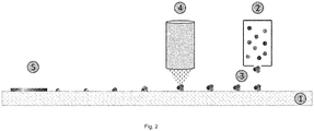
- Fig. 1 3 shows schematically how ceramic pigments 2 of a ceramic color 2 are applied to a substrate 1, which are treated simultaneously with a laser beam of a laser 4, so that the pigments can melt and be cured by subsequent cooling.
- a method according to the invention is shown in which applied to a substrate 1 ceramic pigments 3 of a ceramic paint 2 at a certain location on the substrate 1.
- the heating of the applied ceramic pigments 3 takes place on the same substrate 1 at the same time by the laser beam of a laser 4, but not at the same point at which the ceramic paint 2 is applied to the substrate 1.
- a printed surface 5 can be formed on the glass substrate 1.
- Fig. 3 shows a method according to the invention, in which ceramic pigments 3 of a ceramic paint 2 are applied to a substrate 1 from one side.
- the laser beam is focused in such a way that its focal point is not in the substrate 1, but only at the point at which the ceramic pigments 3 of the ceramic paint 2 to be melted. Again through Cooling of the ceramic pigments produces here a printed surface 5 on the substrate 1.
- a glass substrate is preferably used.
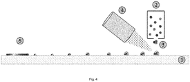
- Fig. 4 shows a method according to the invention, in which on a substrate 1 ceramic pigments 3 of a ceramic paint 2 are applied, which are melted directly at the point where they are applied to the print head by the laser beam of a laser 4. By cooling the ceramic pigments 3 on the substrate 1, a printed surface 5 is formed.
- Fig. 5 schematically shows a method according to the invention, in which the laser 4 is integrated in the printhead of the digital printing device, so that the ceramic pigments 3 of the ceramic paint 2 are heated to their melting temperature during application to the substrate 1. Again, by cooling the ceramic pigments 3, a printed surface 5 is formed on the substrate 1.
- Fig. 6 schematically shows a method according to the invention, in which two different lasers 4 are irradiated.
- the first laser 4 is preferably used to melt the ceramic 3 in the ceramic paint 2. This laser is preferably located on the side from which the ceramic paint 2 is applied to the substrate 1.
- the second laser 4 is preferably used to melt the substrate 1 on the surface at which the ceramic paint 2 is applied.
- the latter laser 4 preferably radiates from the side opposite to the side from which the ceramic paint 2 is applied.
- Fig. 7 a method according to the prior art shown in which a substrate 1 is first printed with ceramic pigments 3 and only after the printing process, the melting and curing of the ceramic pigments 3 takes place in a tempering furnace 6. Only after the removal of the printed substrate 1 from the tempering furnace 6 does the cooling of the molten ceramic pigments allow the formation of a printed surface 5.
Landscapes
- Health & Medical Sciences (AREA)
- General Health & Medical Sciences (AREA)
- Toxicology (AREA)
- Engineering & Computer Science (AREA)
- Optics & Photonics (AREA)
- Physics & Mathematics (AREA)
- Chemical & Material Sciences (AREA)
- Chemical Kinetics & Catalysis (AREA)
- Life Sciences & Earth Sciences (AREA)
- General Chemical & Material Sciences (AREA)
- Geochemistry & Mineralogy (AREA)
- Materials Engineering (AREA)
- Organic Chemistry (AREA)
- Ceramic Engineering (AREA)
- Application Of Or Painting With Fluid Materials (AREA)
- Laser Beam Processing (AREA)
- Printing Methods (AREA)
- Surface Treatment Of Glass (AREA)
Abstract
Description
- Die vorliegende Erfindung betrifft ein Verfahren zum digitalen Drucken einer Keramikfarbe auf einem Substrat, wobei die Keramik der Keramikfarbe auf mindestens den Schmelzpunkt der Keramik mittels eines Laserstrahls simultan zu dem Aufbringen der Keramikfarbe auf ein Substrat mittels eines Druckkopfes erwärmt wird. Weiterhin betrifft die vorliegende Erfindung auch die Verwendung eines Laserstrahls in einer Vorrichtung zum digitalen Drucken einer Keramikfarbe auf einem Substrat, wobei der Laserstrahl die Keramik der Keramikfarbe auf mindestens den Schmelzpunkt der Keramik simultan zu dem Aufbringen der Keramikfarbe auf ein Substrat mittels eines Druckkopfes der Vorrichtung erwärmt. Die vorliegende Erfindung betrifft weiterhin auch eine Vorrichtung zum digitalen Drucken einer Keramikfarbe auf einem Substrat, die einen Druckkopf zum Aufbringen einer Keramikfarbe auf ein Substrat sowie einen Laser zum Erwärmen der Keramik der Keramikfarbe auf mindestens den Schmelzpunkt der Keramik mittels eines Laserstrahls umfasst.
- Bei heutigen Druckverfahren sind prinzipiell zwei Hauptmerkmale zu unterscheiden, zum einen die Bedruckungstechnik, zum anderen das Druckmedium (Farbe). Als Bedruckungstechnik hat sich Digitaldruck auf Glas mittlerweile neben Walzendruck und Spritzen als Industriestandard etabliert. Im Gegensatz zur Siebdrucktechnik ist die Digitaldrucktechnik sehr viel flexibler und als "rapid-prototyping-Verfahren" wesentlich schneller verfügbar. Während beim Siebdruck ein aufwändiger Prozess von der Siebherstellung über den eigentlichen Druck bis zur anschließenden Aushärtung der Farben durchlaufen werden muss, liegt beim Digitaldruck das Druckergebnis meist am gleichen Tag vor, da je nach Druckkopftechnologie die Farbe direkt auf das Substrat aufgetragen wird und diese nach kurzer Zeit selbstständig aushärtet (z.B. durch UV-Härtung oder IR-Strahlung). Die Siebdrucktechnik hat ihre Vorteile bei größeren Auflagen identischer Motive (Serienproduktion), während die Digitaldrucktechnik ihre Stärke bei kleineren Auflagen bis hin zu Einzelanfertigungen hat. Bislang galt der Siebdruck in Bezug auf Druckqualität dem Digitaldruck als überlegen. Allerdings ist am Markt zunehmend schnellere Verfügbarkeit und höhere Flexibilität gefragt, zudem reicht die Qualität durch neue UV-Digitaldruckmaschinen nahezu an das Ergebnis des Siebdrucks heran. Entsprechende Digitaldruckmaschinen sind beispielsweise bei der Fa. Thieme (www.thieme-products.de) oder Fa. Durst (www.durst-online.com) erhältlich. Das zweite Hauptunterscheidungsmerkmal ist das Druckmedium, die Farbe. Während im Siebdruckbereich bislang hauptsächlich mit UV-härtenden Tinten auf organischer Basis gearbeitet wurde, kommen in letzter Zeit zunehmend keramische Farben zum Einsatz. Der größte Vorteil von Keramikfarben ist die hohe mechanische Festigkeit, die insbesondere im Industriebereich in Verbindung mit Glas zunehmend gefordert wird. Hintergrund ist die erforderliche Langzeitstabilität bei Produkten, die eine Bedienoberfläche aus Glas aufweisen und in rauer Umgebung mit wechselnden Temperaturen eingesetzt werden (z.B. Displays, Smartphones, Bedienelemente...). Keramikfarben können seit längerem im Siebdruck verarbeitet werden und sind mittlerweile auch im Digitaldruck am Markt verfügbar. Alle Druckfarben haben diesbezüglich jedoch eines gemeinsam: Zur Aushärtung der Keramikfarbe ist immer ein anschließendes Einbrennen der Farbe auf dem Substrat erforderlich.
- Das große Problem bei derzeit verwendeten Keramikfarben ist die hohe Schmelztemperatur, die zur Aushärtung erforderlich ist (ca. 600°C bis 1400°C, je nach Farbmischung/-zusammensetzung). Bislang ist kein Verfahren bekannt, das Keramikfarben bereits am Druckkopf synchron zur Farbaufbringung aushärten kann. Die anschließende Farbaushärtung erfolgt sowohl beim Siebdruck als auch beim Digitaldruck in der Regel in einem sogenannten Vorspannofen bei Temperaturen über 600°C. Weiterhin bringt eine anschließende Farbaushärtung in einem Ofen auch den Nachteil mit sich, dass das Substrat, auf das aufgedruckt wird, bei den für die Farbaushärtung erforderlichen Temperaturen stabil sein muss.
- Es war deshalb die Aufgabe der vorliegenden Erfindung, ein Verfahren, beziehungsweise eine Vorrichtung zum Digitaldruck von Keramikfarben bereitzustellen, mit dem die bisher relativ lange Prozesszeit und die geringe Flexibilität verbessert werden kann, beziehungsweise auch Keramikfarben verwendet werden können, deren Schmelzpunkte oberhalb der Schmelzpunkte des Substrats, auf das sie aufgebracht werden, liegen.
- Zur Lösung der genannten Aufgabe stellt die vorliegende Erfindung ein Verfahren zum digitalen Drucken einer Keramikfarbe auf einem Substrat bereit, das die folgenden Schritte umfasst:
- (a) Aufbringen einer Keramikfarbe auf ein Substrat mittels eines Druckkopfes eines Digitaldruckgerätes; und
- (b) Erwärmen der Keramikfarbe auf mindestens den Schmelzpunkt der Keramik mittels eines Laserstrahls,
- Alternativ betrifft die vorliegende Erfindung auch ein Verfahren zur Herstellung eines bedruckten Substrats, bei dem die zuvor genannten Schritte (a) und (b) durchgeführt werden und ebenso simultan zueinander stattfinden. Alle hierin genannten bevorzugten Ausführungsformen für das erfindungsgemäße Verfahren zum digitalen Drucken gelten gleichermaßen für das Verfahren zur Herstellung eines bedruckten Substrats.
- Unter dem Begriff "simultan" wird in der vorliegenden Erfindung verstanden, dass der Schritt (b) des Erwärmens der Keramik zeitgleich an dem gleichen Substrat durchgeführt wird, an dem auch der Schritt (a) des Aufbringens der Keramikfarbe durchgeführt wird. Das heißt nicht, dass der Schritt (b) ortsgleich zu dem Schritt (a) durchgeführt werden muss, jedoch kann dies auch der Fall sein.
- Als Digitaldruckgeräte können beispielsweise Geräte genommen werden, wie sie dem Fachmann in diesem Gebiet aus dem Stand der Technik bekannt sind, mit der Maßgabe, dass diese Geräte mit einem Laser kombiniert werden, der den Schritt (b) des erfindungsgemäßen Verfahrens durchführen kann. Entsprechende Digitaldruckgeräte sind beispielsweise bei der Fa. Longier, Fa. Thieme (www.thieme-products.de) oder Fa. Durst (www.durst-online.com) erhältlich, beispielsweise der Longier Performer FG3750 der Fa. Longier oder die Rho Vetrocer Modelle 160, 250 oder 330 der Fa. Durst.
- Unter "DigitaldrucK" wird eine Gruppe von Druckverfahren verstanden, bei denen das Druckbild direkt von einem Computer in eine Druckmaschine übertragen wird, ohne dass eine statische Druckform benutzt wird.
- Das Substrat, auf das die Keramikfarbe aufgebracht wird, ist vorzugsweise ein Substrat, das bei Temperaturen bis zu 2000°C, stärker bevorzugt 1000°C und am stärksten bevorzugt 800°C temperaturstabil ist. Das Substrat kann ein Metall-, Keramik- oder Glassubstrat sein. Als Keramiken können alle technischen Keramiken verwendet werden. Als Metall kommt vorzugsweise Stahl in Betracht. Das Substrat ist jedoch vorzugsweise ein Glassubstrat, wobei alle denkbaren Gläser verwendet werden können, die eine ausreichend hohe Temperaturstabilität haben. Beispiele hierfür sind Floatglas und Verbundsicherheitsglas.
- Die Keramikfarbe ist vorzugsweise eine Farbe, bei der Keramikpigmente suspendiert/dispergiert in einem Lösungsmittel vorliegen. In anderen Worten ist die Keramikfarbe eine Suspension/Dispersion von Keramikpigmenten in einem Lösungsmittel. Bekannt sind solche Keramikfarben als Keramiktinten. Die Keramikfarbe kann auch neben den Keramikpigmenten und dem Lösungsmittel weitere Zusatzstoffe enthalten, wie beispielsweise anorganische Glas-Fritten sowie Dispergier- und Trägerflüssigkeiten. Als Keramikfarbe (auch Keramiktinte genannt) kann erfindungsgemäß beispielsweise anorganische Durst Rho Vetrocer Keramiktinte der Fa. Durst verwendet werden. Es ist jedoch bevorzugt, dass die Keramikfarben, die erfindungsgemäß verwendet werden, keine strahlungshärtenden Zusatzstoffe enthalten, da die Aushärtung nicht mithilfe dieser strahlungshärtenden Zusatzstoffe erfolgen soll, sondern indem die Keramikpigmente aufgeschmolzen und anschließend durch Abkühlung wieder ausgehärtet werden. Besonders bevorzugt sollen die Keramikpigmente sich mit dem Substrat verbinden, indem es während dem Aufschmelzen der Keramikpigmente auch zu einem Aufschmelzen der Substratoberfläche bzw. des Substratmaterials an der Substratoberfläche, insbesondere Glas, kommt. Erfindungsgemäß verwendbare Keramikpigmente werden beispielsweise in der
EP 0 768 343 A2 beschrieben. - Als Keramikpigmente sind alle Keramikpigmente denkbar, die bei Temperaturen im Bereich von 500°C bis 3200°C, stärker bevorzugt 600°C bis 2700°C und am stärksten bevorzugt 600°C bis 2000°C aufschmelzbar sind, d.h. deren Schmelztemperaturen in den angegebenen Bereichen liegen. Erfindungsgemäß verwendbare Keramikpigmente sind beispielsweise anorganische Silikate, Titanate, Oxide, Carbide oder Nitride, beispielsweise der Metalle Si, Al, Zr, Be, Ba, B oder Ti.
- Die mittlere Teilchengröße der Keramikpigmente in der Keramikfarbe liegt vorzugsweise im Bereich von 0,005 mm bis 0,1 mm, stärker bevorzugt im Bereich von 0,005 mm bis 0,05 mm.
- In Schritt (b) des erfindungsgemäßen Verfahrens wird die Keramik, beziehungsweise die Keramikpigmente der Keramikfarbe auf Temperaturen im Bereich von 550°C bis 3200°C, stärker bevorzugt 600°C bis 2000°C und am stärksten bevorzugt 600°C bis 1500°C erwärmt.
- Nach den Schritten (a) und (b) erlaubt man dem Substrat mit der aufgebrachten Keramikfarbe auf Raumtemperatur abzukühlen, wobei die Keramik aushärtet und eine bedruckte Fläche auf dem Substrat bildet.
- In dem erfindungsgemäßen Verfahren ist es bevorzugt, dass das Erwärmen der Keramik der Keramikfarbe mittels eines Laserstrahls durchgeführt wird, der die Keramik der aufgebrachten Keramikfarbe auf dem Substrat in einem Punkt fokussiert erwärmt. In anderen Worten wird der Laser auf einen gewünschten Punkt mit einer bestimmten Temperatur fokussiert, an dem die Keramikpigmente der Keramikfarbe geschmolzen werden sollen.
- Das in einem Punkt fokussierte Erwärmen findet vorzugsweise mit einer Zeitdauer im Bereich von 100 fs bis 1 µs, noch stärker bevorzugt im Bereich von 1 ps bis 10 ns statt.
- Der Punkt, auf den der Laserstrahl zum Erwärmen der Keramik fokussiert wird, weist vorzugsweise einen Durchmesser im Bereich von 0,1 µm bis 15 mm, stärker bevorzugt 0,05 mm bis 10 mm auf. Weiterhin ist es bevorzugt, dass das Erwärmen der Keramik der Keramikfarbe mittels eines Laserstrahls durch pulsierte Lasereinstrahlung stattfindet. In anderen Worten wird vorzugsweise ein pulsierter Laserstrahl verwendet. Der einzelne Puls der Lasereinstrahlung liegt hier vorzugsweise im Bereich von 0,5 ps bis 10 ns, stärker bevorzugt im Bereich von 1 ps bis 5 ns. Die Pulsfrequenz liegt vorzugsweise im Bereich von 1 Hz bis 1000 Hz. Die Verwendung von pulsierter Lasereinstrahlung hat erfindungsgemäß den Vorteil, dass durch die geringe Zeitdauer des Pulses zwar die relativ kleinen Keramikpigmente auf ihre Schmelztemperatur erwärmt werden können, das Substrat jedoch diesen Temperaturen durch seine größere räumliche Ausdehnung nicht ausgesetzt wird. Durch die kurze Einstrahlungsdauer kann die Energie besser im Substrat verteilt werden, so dass eine Beschädigung des Substrats, beispielsweise durch Rissbildung, verhindert werden kann. Auf diese Weise können mit dem erfindungsgemäßen Verfahren auch Keramikpigmente geschmolzen werden, deren Schmelztemperatur oberhalb der Schmelztemperatur des Substrats liegt.
- Der Laserstrahl zum Erwärmen der Keramik der Keramikfarbe kann von der gleichen Seite des Substrats eingestrahlt werden, auf der die Keramikfarbe aufgebracht wird. Besonders bevorzugt ist es jedoch, dass der Laserstrahl zum Erwärmen der Keramik der Keramikfarbe von der Seite des Substrats eingestrahlt wird, die der Seite gegenüber liegt, auf der die Keramikfarbe aufgebracht wird, d.h. der Laserstrahl wird durch das Substrat hindurch auf den Punkt fokussiert, an dem sich die zu schmelzende Keramik befindet. Hierbei ist es bevorzugt, dass das Substrat aus einem transparenten Material, z.B. Glas besteht. Auf diese Weise kann im Gegensatz zur Einstrahlung von der Seite, auf der die Keramikfarbe aufgebracht wird, auch das Glas an der Oberfläche, auf die die Keramikfarbe aufgebracht wird, zum Schmelzen gebracht werden. Damit kann es zu einer homogenen Verbindung der Keramik der Keramikfarbe und der Substratoberfläche kommen. Hier ist es auch vorteilhaft, einen pulsierten Laserstrahl zu verwenden, da auf diese Weise die Einstrahlungsdauer verkürzt werden kann, so dass der Laserstrahl auf dem Weg durch das Substrat dieses nicht - beispielsweise durch Rissbildung - beschädigt.
- In einer weiteren Ausführungsform der vorliegenden Erfindung erfolgt der Schritt (b) des erfindungsgemäßen Verfahrens dadurch, dass die Keramikfarbe durch Einstrahlen zweier Laserstrahlen erfolgt, wobei ein erster Laserstrahl die Keramik erwärmt und ein zweiter Laserstrahl die Substratoberfläche aufschmilzt. Hierbei ist es bevorzugt, wenn der erste Laserstrahl von der Seite des Substrats, auf der die Keramik aufgebracht wird, eingestrahlt wird, und ein zweiter Laserstrahl von der Seite des Substrats eingestrahlt wird, die sich der Seite gegenüber befindet, auf der die Keramik aufgebracht wird. Dies hat den Vorteil, dass mit dem ersten Laserstrahl die Keramik in der Keramikfarbe und mit dem zweiten Laserstrahl die Substratoberfläche geschmolzen werden kann. In dieser Ausführungsform ist die Verbindung zwischen Keramik und Substrat besonders homogen. Die Einstrahlung von nur der Seite, auf der die Keramikfarbe aufgebracht wird, reicht oft nicht aus, um auch die Substratoberfläche zu schmelzen, um eine homogene Verbindung zwischen Keramik und Substrat zu gewährleisten. Besonders bevorzugt ist es erfindungsgemäß, dass der erste und der zweite Laserstrahl im Wesentlichen zeitgleich eingestrahlt werden.
- Die Keramikpigmente beziehungsweise die Keramik der Keramikfarbe können schon vor dem Auftreffen des Substrats erwärmt werden, d.h. auf dem Weg von dem Druckkopf des Digitaldruckgerätes zu dem Substrat, so dass die Keramikpigmente bereits in geschmolzener Form auf dem Substrat auftreffen.
- Weiterhin können die Keramikpigmente jedoch auch erst bis zu ihrem Schmelzpunkt erwärmt werden, wenn sie sich bereits auf dem Substrat befinden.
- Mögliche verwendbare Laserquellen sind beispielsweise CO2-Laser, Nd:YAG-Laser, Excimer-Laser oder ein Diodenlaser. Dabei liegt die Laserleistung vorzugsweise im Bereich von 10 W bis 500 W, stärker bevorzugt im Bereich von 20 W bis 100 W. Die Pulsenergie des Lasers liegt vorzugsweise im Bereich von 10 mJ bis 1000 mJ , stärker bevorzugt im Bereich von 200 mJ bis 600 mJ. Die Wellenlänge des Lasers hängt von der Art des verwendeten Lasers ab und kann bei einem Excimer-Laser bei 193 nm, 248 nm, 308 nm oder 351 nm, bei einem CO2-Laser bei 10,6 µm oder 9,4 µm, und bei einem Nd:YAG-Laser bei 1064 nm, 946 nm, 1320 nm oder 1444 nm liegen.
- Ist es beabsichtigt, eine Aufschmelzung des Substrats zu erzielen, so ist es erfindungsgemäß bevorzugt, im UV-Bereich bzw. im nahen IR-Bereich einzustrahlen, da insbesondere bei der Verwendung von Glas als Substrat eine Absorption in diesen Bereichen stattfinden kann, die zu einer Erwärmung führt. Im UV-Bereich sind Wellenlängen im Bereich von 150 nm bis 355 nm und im nahen IR-Bereich Wellenlängen von 5 µm bis 11 µm erfindungsgemäß bevorzugt.
- Das erfindungsgemäße Verfahren ermöglicht weiterhin aufgrund einer schnellen Energiemodulation durch Temperatureinflüsse die Variation der Farbzusammensetzung beziehungsweise der Farbwerte gemäß der sogenannten RAL-Farbtabelle.
- Weiterhin kann in einem Digitaldrucksystem für Keramikfarben die Strahlungsquelle beziehungsweise der Laser für das Erwärmen der Keramikfarbe im Druckkopf integriert sein. Dabei können die zur Herstellung von Farben nach der RAL-Tabelle erforderlichen Keramikpigmente beziehungsweise Keramikfarben in einem Tanksystem bereitgestellt werden. Dabei wird vorzugsweise eine geeignete Steuerungselektronik zur "intelligenten" Farbmischung im Farbmanagementsystem verwendet.
- Ein weiterer Gegenstand der vorliegenden Erfindung ist die Verwendung eines Laserstrahls beziehungsweise eines Lasers in einer Vorrichtung zum digitalen Drucken einer Keramikfarbe auf einem Substrat, wobei der Laserstrahl die Keramik der Keramikfarbe auf mindestens den Schmelzpunkt der Keramik simultan zu dem Aufbringen der Keramikfarbe auf ein Substrat mittels eines Druckkopfes zur Vorrichtung erwärmt.
- Ein noch weiterer Gegenstand der vorliegenden Erfindung betrifft eine Vorrichtung zum digitalen Drucken einer Keramikfarbe auf einem Substrat, die einen Druckkopf zum Aufbringen einer Keramikfarbe auf ein Substrat sowie einen Laser zum Erwärmen der Keramik der Keramikfarbe auf mindestens den Schmelzpunkt der Keramik mittels eines Laserstrahls umfasst. In einer bevorzugten Variante der erfindungsgemäßen Vorrichtung weist diese einen ersten und einen zweiten Laser auf, die - wie weiter oben beschrieben - zur Einstrahlung des ersten und des zweiten Laserstrahls dienen können.
- Alle für das erfindungsgemäße Verfahren bevorzugten Merkmale betreffen auch die erfindungsgemäße Verwendung beziehungsweise die erfindungsgemäße Vorrichtung.
- Das erfindungsgemäße Verfahren, die erfindungsgemäße Verwendung und die erfindungsgemäße Vorrichtung zum digitalen Drucken einer Keramikfarbe auf einem Substrat bringen die folgenden Vorteile mit sich:
- Das simultane Aufschmelzen der Keramikpigmente der Keramikfarbe während des Druckvorgangs ermöglicht die Fertigstellung eines gedruckten Objekts mit Keramikfarben in viel geringerer Zeit, als wenn entsprechend bedruckte Substrate zur Aufschmelzung und Aushärtung der Keramikfarben in einem Vorspannofen behandelt werden müssen.
- Die Verwendung eines Lasers zum Erwärmen beziehungsweise Aufschmelzen der Keramikpigmente der Keramikfarbe in einem fokussierten Punkt ermöglicht es, auch Keramikfarben zu verwenden, die eine höhere Schmelztemperatur als das Substrat besitzen. Entsprechende Keramikfarben können aufgrund der Temperaturbehandlung in einem Vorspannofen bisher nicht in Druckverfahren verwendet werden.
- Durch die Möglichkeit der breiteren Verwendung von Keramikpigmenten ist es möglich, ein intelligentes Farbsystem bereitzustellen, das alle Farbtöne der RAL-Farbtabelle ermöglicht.
- Gegenüber der Ink-Jet-Technologie (mit organischer Farbe und UV-Härtung) besitzt Keramikfarbe eine weitaus höhere Festigkeit, so dass der Digitaldruck von Keramikfarben einen sehr hohen Industriestandard erfüllt.
- Die vorliegende Erfindung soll nun schematisch anhand der
Fig. 1 bis 6 erläutert werden. Sofern technisch realisierbar, können alle mit den einzelnen Ausführungsformen in denFig. 1 bis 6 genannten bevorzugten Merkmale auch jeweils in den jeweils anderen Ausführungsformen verwendet werden, so dass die Nennung von bevorzugten Ausführungsformen in Verbindung mit einer bestimmten Figur keine Einschränkung auf die darin gezeigte Ausführungsform darstellt, sondern auch auf die in den anderen Figuren gezeigten Ausführungsformen übertragen werden kann. - Fig. 1:
-
Fig. 1 zeigt schematisch ein erfindungsgemäßes Verfahren mit Erwärmung von Keramikpigmenten mittels eines Laserstrahls. - Fig. 2:
-
Fig. 2 zeigt ein erfindungsgemäßes Verfahren, wobei das Aufschmelzen der Keramikpigmente der Keramikfarbe zeitgleich, aber nicht ortsgleich auf dem gleichen Substrat durchgeführt wird. - Fig. 3:
-
Fig. 3 zeigt ein erfindungsgemäßes Verfahren, worin der Laserstrahl von der dem Druckkopf gegenüberliegenden Seite des Substrats auf die Keramikpigmente der Keramikfarbe fokussiert wird. - Fig. 4:
-
Fig. 4 zeigt ein erfindungsgemäßes Verfahren, bei dem die Einstrahlung des Lasers zeit- und ortsgleich zu dem Aufbringen der Keramikpigmente auf dem Substrat erfolgt. - Fig. 5:
- Die
Fig. 5 zeigt ein erfindungsgemäßes Verfahren, bei dem der Laser in dem Druckkopf integriert ist. - Fig. 6:
- Die
Fig. 6 zeigt ein erfindungsgemäßes Verfahren, bei dem mit zwei verschiedenen Lasern eingestrahlt wird. - Fig. 7:
- Die
Fig. 7 zeigt ein Verfahren nach dem Stand der Technik, bei dem das Aushärten der Keramikfarbe in einem getrennten Vorspannofen stattfindet. - In
Fig. 1 wird schematisch gezeigt, wie auf ein Substrat 1 Keramikpigmente 3 einer Keramikfarbe 2 aufgebracht werden, die simultan mit einem Laserstrahl eines Lasers 4 behandelt werden, so dass die Pigmente schmelzen und durch anschließendes Wiederabkühlen ausgehärtet werden können. - In
Fig. 2 ist schematisch ein erfindungsgemäßes Verfahren gezeigt, bei dem auf ein Substrat 1 Keramikpigmente 3 einer Keramikfarbe 2 an einem bestimmten Ort auf das Substrat 1 aufgebracht werden. Das Erwärmen der aufgebrachten Keramikpigmente 3 erfolgt auf dem gleichen Substrat 1 zwar zeitgleich durch den Laserstrahl eines Lasers 4, jedoch nicht an der gleichen Stelle an der die Keramikfarbe 2 auf das Substrat 1 aufgebracht wird. Nach dem Abkühlen der auf Schmelztemperatur gebrachten Keramikpigmente kann eine bedruckte Fläche 5 auf dem Glassubstrat 1 entstehen. -
Fig. 3 zeigt ein erfindungsgemäßes Verfahren, bei dem auf ein Substrat 1 von einer Seite Keramikpigmente 3 einer Keramikfarbe 2 aufgebracht werden. Von der anderen Seite des Substrats 1 erfolgt die Einstrahlung eines Laserstrahls durch einen dort angebrachten Laser 4. Dabei wird der Laserstrahl so fokussiert, dass sein Brennpunkt nicht in dem Substrat 1 ist, sondern erst an der Stelle, an der die Keramikpigmente 3 der Keramikfarbe 2 geschmolzen werden sollen. Wiederum durch Abkühlen der Keramikpigmente entsteht hier eine bedruckte Fläche 5 auf dem Substrat 1. Hier wird vorzugsweise ein Glassubstrat verwendet. -
Fig. 4 zeigt ein erfindungsgemäßes Verfahren, bei dem auf einem Substrat 1 Keramikpigmente 3 einer Keramikfarbe 2 aufgebracht werden, die direkt an der Stelle, an der sie auf dem Druckkopf aufgebracht werden, durch den Laserstrahl eines Lasers 4 geschmolzen werden. Durch Abkühlen der Keramikpigmente 3 auf dem Substrat 1 entsteht eine bedruckte Fläche 5. -
Fig. 5 zeigt schematisch ein erfindungsgemäßes Verfahren, bei dem der Laser 4 in dem Druckkopf des Digitaldruckgerätes integriert ist, so dass die Keramikpigmente 3 der Keramikfarbe 2 während dem Auftragen auf das Substrat 1 auf ihre Schmelztemperatur erwärmt werden. Wiederum durch Abkühlen der Keramikpigmente 3 entsteht eine bedruckte Fläche 5 auf dem Substrat 1. -
Fig. 6 zeigt schematisch ein erfindungsgemäßes Verfahren, bei dem mit zwei verschiedenen Lasern 4 eingestrahlt wird. Der erste Laser 4 wird vorzugsweise dafür verwendet, die Keramik 3 in der Keramikfarbe 2 zu schmelzen. Dieser Laser befindet sich vorzugsweise auf der Seite, von der auch die Keramikfarbe 2 auf das Substrat 1 aufgebracht wird. Der zweite Laser 4 wird vorzugsweise dafür verwendet, das Substrat 1 an der Oberfläche aufzuschmelzen, an der die Keramikfarbe 2 aufgebracht wird. Der zuletzt genannte Laser 4 strahlt vorzugsweise von der Seite ein, die der Seite gegenüberliegt, von der die Keramikfarbe 2 aufgebracht wird. - Im Vergleich zu dem erfindungsgemäßen Verfahren ist in
Fig. 7 ein Verfahren nach dem Stand der Technik dargestellt, bei dem ein Substrat 1 zunächst mit Keramikpigmenten 3 bedruckt wird und erst nach dem Druckvorgang das Aufschmelzen und Aushärten der Keramikpigmente 3 in einem Vorspannofen 6 erfolgt. Erst nach dem Herausnehmen des bedruckten Substrats 1 aus dem Vorspannofen 6 erlaubt das Abkühlen der geschmolzenen Keramikpigmente die Bildung einer bedruckten Fläche 5. -
- 1
- Substrat
- 2
- Keramikfarbe
- 3
- Keramikpigmente/Keramik
- 4
- Laser
- 5
- Bedruckte Fläche
- 6
- Vorspannofen
Claims (15)
- Verfahren zum digitalen Drucken einer Keramikfarbe (2) auf einem Substrat (1), das die folgenden Schritte umfasst:(a) Aufbringen einer Keramikfarbe (2) auf ein Substrat (1) mittels eines Druckkopfes eines Digitaldruckgerätes; und(b) Erwärmen der Keramik (3) der Keramikfarbe (2) auf mindestens den Schmelzpunkt der Keramik (3) mittels eines Laserstrahls eines Lasers (4),dadurch gekennzeichnet, dass
der Schritt (b) simultan zu dem Schritt (a) stattfindet. - Verfahren nach Anspruch 1, worin das Substrat (1) ein Glas-, Metall- oder Keramiksubstrat ist.
- Verfahren nach Anspruch 1 oder 2, wobei die Keramikfarbe (2) Keramikpigmente (3) enthält.
- Verfahren nach einem der Ansprüche 1 bis 3, worin in Schritt (b) die Keramik der Keramikfarbe (2) auf Temperaturen im Bereich von 600 °C bis 3200 °C erwärmt wird.
- Verfahren nach einem der Ansprüche 1 bis 4, worin das Erwärmen der Keramik der Keramikfarbe (2) mittels eines Laserstrahls durchgeführt wird, der die Keramik der aufgebrachten Keramikfarbe (2) auf dem Substrat (1) in einem Punkt fokussiert erwärmt.
- Verfahren nach Anspruch 5, worin das in einem Punkt fokussierte Erwärmen mit einer Zeitdauer im Bereich von 100 fs bis 1 µs stattfindet.
- Verfahren nach Anspruch 5 oder 6, worin der Punkt einen Durchmesser im Bereich von 0,1 µm bis 15 mm aufweist.
- Verfahren nach einem der Ansprüche 1 bis 6, worin das Erwärmen der Keramik der Keramikfarbe (2) mittels eines Laserstrahls durch pulsierte Lasereinstrahlung stattfindet.
- Verfahren nach Anspruch 8, worin der Puls der Lasereinstrahlung im Bereich von 0,5 ps bis 10 ns liegt.
- Verfahren nach einem der Ansprüche 1 bis 9, worin mit einem ersten Laserstrahl das Erwärmen der Keramik und mit einem zweiten Laserstrahl ein Aufschmelzen der Oberfläche des Substrats erfolgt.
- Verfahren nach einem der Ansprüche 1 bis 9, worin das Erwärmen der Keramik der Keramikfarbe (2) mittels eines Laserstrahls durchgeführt wird, der von der gleichen Seite des Substrats (1) einstrahlt, auf der die Keramikfarbe (2) aufgebracht wird, oder mittels eines Laserstrahls durchgeführt wird, der von der Seite des Substrats (1) einstrahlt, die der Seite gegenüberliegt, auf der die Keramikfarbe (2) aufgebracht wird.
- Verfahren nach Anspruch 10, worin der erste Laserstrahl von der gleichen Seite des Substrats (1) einstrahlt, auf der die Keramikfarbe (2) aufgebracht wird, und der zweite Laserstrahl von der Seite des Substrats (1) einstrahlt, die der Seite gegenüberliegt, auf der die Keramikfarbe (2) aufgebracht wird.
- Verfahren nach einem der Ansprüche 1 bis 12, worin der Schritt (b) simultan zu dem Schritt (a) an der gleichen oder einer anderen Stelle des Substrats (1) durchgeführt wird.
- Verwendung eines Laserstrahls in einer Vorrichtung zum digitalen Drucken einer Keramikfarbe (2) auf einem Substrat (1), wobei der Laserstrahl eines Lasers (4) die Keramik (3) der Keramikfarbe (2) auf mindestens den Schmelzpunkt der Keramik simultan zu dem Aufbringen der Keramikfarbe auf ein Substrat mittels eines Druckkopfes der Vorrichtung erwärmt.
- Vorrichtung zum digitalen Drucken einer Keramikfarbe (2) auf einem Substrat (1), die einen Druckkopf zum Aufbringen einer Keramikfarbe (2) auf ein Substrat (1) sowie einen Laser (4) zum Erwärmen der Keramik der Keramikfarbe auf mindestens den Schmelzpunkt der Keramik mittels eines Laserstrahls umfasst.
Applications Claiming Priority (1)
| Application Number | Priority Date | Filing Date | Title |
|---|---|---|---|
| DE102015119618.2A DE102015119618B3 (de) | 2015-11-13 | 2015-11-13 | Digitaldruckverfahren für Keramikfarben |
Publications (2)
| Publication Number | Publication Date |
|---|---|
| EP3170673A1 true EP3170673A1 (de) | 2017-05-24 |
| EP3170673B1 EP3170673B1 (de) | 2019-07-03 |
Family
ID=57288284
Family Applications (1)
| Application Number | Title | Priority Date | Filing Date |
|---|---|---|---|
| EP16198615.3A Active EP3170673B1 (de) | 2015-11-13 | 2016-11-14 | Digitaldruckverfahren für keramikfarben |
Country Status (2)
| Country | Link |
|---|---|
| EP (1) | EP3170673B1 (de) |
| DE (1) | DE102015119618B3 (de) |
Families Citing this family (2)
| Publication number | Priority date | Publication date | Assignee | Title |
|---|---|---|---|---|
| DE102018118964A1 (de) * | 2018-08-03 | 2020-02-06 | Flachglas Wernberg Gmbh | Verfahren zur Herstellung von zumindest einer teilflächigen keramischen Bedruckung auf einem mit einer vorspannbaren Funktionsbeschichtung versehenen Floatglasssubstrat |
| EP3650238B1 (de) * | 2018-11-09 | 2022-01-05 | FRAUNHOFER-GESELLSCHAFT zur Förderung der angewandten Forschung e.V. | Verfahren zur markierung von werkstücken |
Citations (4)
| Publication number | Priority date | Publication date | Assignee | Title |
|---|---|---|---|---|
| EP0768343A2 (de) | 1995-10-14 | 1997-04-16 | BASF Aktiengesellschaft | Goniochromatische Glanzpigmente mit siliciumhaltiger Beschichtung |
| EP1371496A2 (de) * | 2002-06-14 | 2003-12-17 | Schott Glas | Gegenstand aus Glas oder Keramik mit aufgebrachtem Aufdruck |
| EP2436527A2 (de) * | 2010-06-14 | 2012-04-04 | Tecglass SL | Maschine und Verfahren für digitalen Tintenstrahlglasdruck mit gleichzeitigem Trocknen |
| WO2015023612A2 (en) * | 2013-08-15 | 2015-02-19 | Oxane Materials, Inc. | Additive fabrication of proppants |
Family Cites Families (1)
| Publication number | Priority date | Publication date | Assignee | Title |
|---|---|---|---|---|
| DE102004049955B4 (de) * | 2004-10-13 | 2008-12-04 | Schott Ag | Verfahren zur Herstellung eines optischen Bauelements, insbesondere einer OLED |
-
2015
- 2015-11-13 DE DE102015119618.2A patent/DE102015119618B3/de not_active Expired - Fee Related
-
2016
- 2016-11-14 EP EP16198615.3A patent/EP3170673B1/de active Active
Patent Citations (4)
| Publication number | Priority date | Publication date | Assignee | Title |
|---|---|---|---|---|
| EP0768343A2 (de) | 1995-10-14 | 1997-04-16 | BASF Aktiengesellschaft | Goniochromatische Glanzpigmente mit siliciumhaltiger Beschichtung |
| EP1371496A2 (de) * | 2002-06-14 | 2003-12-17 | Schott Glas | Gegenstand aus Glas oder Keramik mit aufgebrachtem Aufdruck |
| EP2436527A2 (de) * | 2010-06-14 | 2012-04-04 | Tecglass SL | Maschine und Verfahren für digitalen Tintenstrahlglasdruck mit gleichzeitigem Trocknen |
| WO2015023612A2 (en) * | 2013-08-15 | 2015-02-19 | Oxane Materials, Inc. | Additive fabrication of proppants |
Also Published As
| Publication number | Publication date |
|---|---|
| DE102015119618B3 (de) | 2017-03-02 |
| EP3170673B1 (de) | 2019-07-03 |
Similar Documents
| Publication | Publication Date | Title |
|---|---|---|
| EP0432653B1 (de) | Verfahren zur Herstellung von Grossflächendekoren auf Glas, Glaskeramik oder Keramiken und dekorierten Glaskeramikplatten | |
| EP0391848B1 (de) | Laserbeschriftung von keramischen Materialien, Glasuren, keramischen Gläsern und Gläsern | |
| EP2857139B1 (de) | Vorrichtung zur Laser-Materialbearbeitung mit einem entlang einer Raumrichtung beweglichen Laserkopf | |
| DE69816107T2 (de) | Laserbeschriftungsverfahren | |
| DE3888706T2 (de) | Verfahren zum Anbringen von Identifizierungsmarkierungen auf Kathodenstrahlröhren. | |
| EP1052114B1 (de) | Verfahren zur Dekoration fester Materialien | |
| EP3235580B1 (de) | Verfahren und vorrichtung zum herstellen zumindest eines bauteilbereichs eines bauteils | |
| DE69814456T2 (de) | Verfahren und vorrichtung zur markierung von gegenständen unter verwendung von gesinterten mineralpulvern | |
| WO2008125273A1 (de) | Verfahren zum einbringen einer struktur in eine oberfläche eines transparenten werkstücks | |
| DE102014208565A1 (de) | Schnellprototypenbau-Modell, Pulver-Schnellprototypenbau-Vorrichtung und Pulver-Schnellprototypenbau-Verfahren | |
| DE69304721T2 (de) | Verfahren zum Herstellen einer gebogene laminierten Windschutzscheibe aus Glas | |
| DE102015214994A1 (de) | Ein Verfahren zur Herstellung oder Reparatur eines Bauteils und Vorrichtung zur Herstellung und Reparatur eines Bauteils | |
| EP3170673B1 (de) | Digitaldruckverfahren für keramikfarben | |
| WO2019162212A1 (de) | Druckverfahren zur übertragung von drucksubstanz | |
| DE102015008918B4 (de) | Verfahren zur additiven Herstellung von dreidimensionalen Bauteilen | |
| EP3482854A1 (de) | Verfahren zur herstellung eines halbzeugs und eines werkstücks | |
| WO2021229457A1 (de) | Verfahren und vorrichtung zur additiven fertigung eines werkstücks | |
| WO2002083589A1 (de) | Verfahren zur herstellung farbiger strukturen eines glases | |
| DE102012009773A1 (de) | Verfahren und Vorrichtung zum Bedrucken eines Werkstücks aus Glas mit einer Heißprägefolie unter Verwendung eines Prägestempels | |
| EP1478602A1 (de) | Glas mit gehärteter oberflächenschicht und verfahren zu seiner herstellung | |
| EP3763686B1 (de) | Reparatur von fehlstellen in einem glas oder glaskeramischen überzug auf einem metallischen oder keramischen substrat inklusive der substratoberfläche | |
| EP2125382B1 (de) | Verfahren zum beschriften oder markieren von oberflächen | |
| DE102007036739A1 (de) | Verfahren zum Bedrucken von Glasplatten mit Glasfluss | |
| DE2154492A1 (de) | Verfahren zur Herstellung von drei dimensionalen Korpern | |
| DE102016205782A1 (de) | Verfahren und Vorrichtung zum Herstellen zumindest eines Bauteilbereichs eines Bauteils |
Legal Events
| Date | Code | Title | Description |
|---|---|---|---|
| PUAI | Public reference made under article 153(3) epc to a published international application that has entered the european phase |
Free format text: ORIGINAL CODE: 0009012 |
|
| STAA | Information on the status of an ep patent application or granted ep patent |
Free format text: STATUS: THE APPLICATION HAS BEEN PUBLISHED |
|
| AK | Designated contracting states |
Kind code of ref document: A1 Designated state(s): AL AT BE BG CH CY CZ DE DK EE ES FI FR GB GR HR HU IE IS IT LI LT LU LV MC MK MT NL NO PL PT RO RS SE SI SK SM TR |
|
| AX | Request for extension of the european patent |
Extension state: BA ME |
|
| STAA | Information on the status of an ep patent application or granted ep patent |
Free format text: STATUS: REQUEST FOR EXAMINATION WAS MADE |
|
| 17P | Request for examination filed |
Effective date: 20170711 |
|
| RBV | Designated contracting states (corrected) |
Designated state(s): AL AT BE BG CH CY CZ DE DK EE ES FI FR GB GR HR HU IE IS IT LI LT LU LV MC MK MT NL NO PL PT RO RS SE SI SK SM TR |
|
| STAA | Information on the status of an ep patent application or granted ep patent |
Free format text: STATUS: EXAMINATION IS IN PROGRESS |
|
| 17Q | First examination report despatched |
Effective date: 20180102 |
|
| RIC1 | Information provided on ipc code assigned before grant |
Ipc: B41M 5/00 20060101AFI20180717BHEP Ipc: B41J 3/407 20060101ALI20180717BHEP Ipc: B41J 11/00 20060101ALI20180717BHEP Ipc: B41J 2/48 20060101ALI20180717BHEP Ipc: G02B 6/00 20060101ALN20180717BHEP Ipc: B41J 2/455 20060101ALN20180717BHEP |
|
| GRAP | Despatch of communication of intention to grant a patent |
Free format text: ORIGINAL CODE: EPIDOSNIGR1 |
|
| STAA | Information on the status of an ep patent application or granted ep patent |
Free format text: STATUS: GRANT OF PATENT IS INTENDED |
|
| RIC1 | Information provided on ipc code assigned before grant |
Ipc: B41J 2/48 20060101ALI20190117BHEP Ipc: B41J 11/00 20060101ALI20190117BHEP Ipc: B41M 5/00 20060101AFI20190117BHEP Ipc: B41J 3/407 20060101ALI20190117BHEP Ipc: B41J 2/455 20060101ALN20190117BHEP Ipc: G02B 6/00 20060101ALN20190117BHEP |
|
| INTG | Intention to grant announced |
Effective date: 20190131 |
|
| RIC1 | Information provided on ipc code assigned before grant |
Ipc: B41J 2/48 20060101ALI20190118BHEP Ipc: B41J 2/455 20060101ALN20190118BHEP Ipc: G02B 6/00 20060101ALN20190118BHEP Ipc: B41M 5/00 20060101AFI20190118BHEP Ipc: B41J 3/407 20060101ALI20190118BHEP Ipc: B41J 11/00 20060101ALI20190118BHEP |
|
| GRAS | Grant fee paid |
Free format text: ORIGINAL CODE: EPIDOSNIGR3 |
|
| GRAA | (expected) grant |
Free format text: ORIGINAL CODE: 0009210 |
|
| STAA | Information on the status of an ep patent application or granted ep patent |
Free format text: STATUS: THE PATENT HAS BEEN GRANTED |
|
| AK | Designated contracting states |
Kind code of ref document: B1 Designated state(s): AL AT BE BG CH CY CZ DE DK EE ES FI FR GB GR HR HU IE IS IT LI LT LU LV MC MK MT NL NO PL PT RO RS SE SI SK SM TR |
|
| REG | Reference to a national code |
Ref country code: GB Ref legal event code: FG4D Free format text: NOT ENGLISH |
|
| REG | Reference to a national code |
Ref country code: CH Ref legal event code: EP Ref country code: AT Ref legal event code: REF Ref document number: 1150516 Country of ref document: AT Kind code of ref document: T Effective date: 20190715 |
|
| REG | Reference to a national code |
Ref country code: IE Ref legal event code: FG4D Free format text: LANGUAGE OF EP DOCUMENT: GERMAN |
|
| REG | Reference to a national code |
Ref country code: DE Ref legal event code: R096 Ref document number: 502016005345 Country of ref document: DE |
|
| REG | Reference to a national code |
Ref country code: NL Ref legal event code: MP Effective date: 20190703 |
|
| REG | Reference to a national code |
Ref country code: CH Ref legal event code: NV Representative=s name: TROESCH SCHEIDEGGER WERNER AG, CH |
|
| REG | Reference to a national code |
Ref country code: LT Ref legal event code: MG4D |
|
| PG25 | Lapsed in a contracting state [announced via postgrant information from national office to epo] |
Ref country code: HR Free format text: LAPSE BECAUSE OF FAILURE TO SUBMIT A TRANSLATION OF THE DESCRIPTION OR TO PAY THE FEE WITHIN THE PRESCRIBED TIME-LIMIT Effective date: 20190703 Ref country code: BG Free format text: LAPSE BECAUSE OF FAILURE TO SUBMIT A TRANSLATION OF THE DESCRIPTION OR TO PAY THE FEE WITHIN THE PRESCRIBED TIME-LIMIT Effective date: 20191003 Ref country code: PT Free format text: LAPSE BECAUSE OF FAILURE TO SUBMIT A TRANSLATION OF THE DESCRIPTION OR TO PAY THE FEE WITHIN THE PRESCRIBED TIME-LIMIT Effective date: 20191104 Ref country code: NL Free format text: LAPSE BECAUSE OF FAILURE TO SUBMIT A TRANSLATION OF THE DESCRIPTION OR TO PAY THE FEE WITHIN THE PRESCRIBED TIME-LIMIT Effective date: 20190703 Ref country code: LT Free format text: LAPSE BECAUSE OF FAILURE TO SUBMIT A TRANSLATION OF THE DESCRIPTION OR TO PAY THE FEE WITHIN THE PRESCRIBED TIME-LIMIT Effective date: 20190703 Ref country code: NO Free format text: LAPSE BECAUSE OF FAILURE TO SUBMIT A TRANSLATION OF THE DESCRIPTION OR TO PAY THE FEE WITHIN THE PRESCRIBED TIME-LIMIT Effective date: 20191003 Ref country code: CZ Free format text: LAPSE BECAUSE OF FAILURE TO SUBMIT A TRANSLATION OF THE DESCRIPTION OR TO PAY THE FEE WITHIN THE PRESCRIBED TIME-LIMIT Effective date: 20190703 Ref country code: FI Free format text: LAPSE BECAUSE OF FAILURE TO SUBMIT A TRANSLATION OF THE DESCRIPTION OR TO PAY THE FEE WITHIN THE PRESCRIBED TIME-LIMIT Effective date: 20190703 Ref country code: SE Free format text: LAPSE BECAUSE OF FAILURE TO SUBMIT A TRANSLATION OF THE DESCRIPTION OR TO PAY THE FEE WITHIN THE PRESCRIBED TIME-LIMIT Effective date: 20190703 |
|
| PG25 | Lapsed in a contracting state [announced via postgrant information from national office to epo] |
Ref country code: LV Free format text: LAPSE BECAUSE OF FAILURE TO SUBMIT A TRANSLATION OF THE DESCRIPTION OR TO PAY THE FEE WITHIN THE PRESCRIBED TIME-LIMIT Effective date: 20190703 Ref country code: AL Free format text: LAPSE BECAUSE OF FAILURE TO SUBMIT A TRANSLATION OF THE DESCRIPTION OR TO PAY THE FEE WITHIN THE PRESCRIBED TIME-LIMIT Effective date: 20190703 Ref country code: IS Free format text: LAPSE BECAUSE OF FAILURE TO SUBMIT A TRANSLATION OF THE DESCRIPTION OR TO PAY THE FEE WITHIN THE PRESCRIBED TIME-LIMIT Effective date: 20191103 Ref country code: RS Free format text: LAPSE BECAUSE OF FAILURE TO SUBMIT A TRANSLATION OF THE DESCRIPTION OR TO PAY THE FEE WITHIN THE PRESCRIBED TIME-LIMIT Effective date: 20190703 Ref country code: GR Free format text: LAPSE BECAUSE OF FAILURE TO SUBMIT A TRANSLATION OF THE DESCRIPTION OR TO PAY THE FEE WITHIN THE PRESCRIBED TIME-LIMIT Effective date: 20191004 Ref country code: ES Free format text: LAPSE BECAUSE OF FAILURE TO SUBMIT A TRANSLATION OF THE DESCRIPTION OR TO PAY THE FEE WITHIN THE PRESCRIBED TIME-LIMIT Effective date: 20190703 |
|
| PG25 | Lapsed in a contracting state [announced via postgrant information from national office to epo] |
Ref country code: TR Free format text: LAPSE BECAUSE OF FAILURE TO SUBMIT A TRANSLATION OF THE DESCRIPTION OR TO PAY THE FEE WITHIN THE PRESCRIBED TIME-LIMIT Effective date: 20190703 |
|
| PG25 | Lapsed in a contracting state [announced via postgrant information from national office to epo] |
Ref country code: EE Free format text: LAPSE BECAUSE OF FAILURE TO SUBMIT A TRANSLATION OF THE DESCRIPTION OR TO PAY THE FEE WITHIN THE PRESCRIBED TIME-LIMIT Effective date: 20190703 Ref country code: DK Free format text: LAPSE BECAUSE OF FAILURE TO SUBMIT A TRANSLATION OF THE DESCRIPTION OR TO PAY THE FEE WITHIN THE PRESCRIBED TIME-LIMIT Effective date: 20190703 Ref country code: RO Free format text: LAPSE BECAUSE OF FAILURE TO SUBMIT A TRANSLATION OF THE DESCRIPTION OR TO PAY THE FEE WITHIN THE PRESCRIBED TIME-LIMIT Effective date: 20190703 Ref country code: IT Free format text: LAPSE BECAUSE OF FAILURE TO SUBMIT A TRANSLATION OF THE DESCRIPTION OR TO PAY THE FEE WITHIN THE PRESCRIBED TIME-LIMIT Effective date: 20190703 Ref country code: PL Free format text: LAPSE BECAUSE OF FAILURE TO SUBMIT A TRANSLATION OF THE DESCRIPTION OR TO PAY THE FEE WITHIN THE PRESCRIBED TIME-LIMIT Effective date: 20190703 |
|
| PG25 | Lapsed in a contracting state [announced via postgrant information from national office to epo] |
Ref country code: SK Free format text: LAPSE BECAUSE OF FAILURE TO SUBMIT A TRANSLATION OF THE DESCRIPTION OR TO PAY THE FEE WITHIN THE PRESCRIBED TIME-LIMIT Effective date: 20190703 Ref country code: IS Free format text: LAPSE BECAUSE OF FAILURE TO SUBMIT A TRANSLATION OF THE DESCRIPTION OR TO PAY THE FEE WITHIN THE PRESCRIBED TIME-LIMIT Effective date: 20200224 Ref country code: SM Free format text: LAPSE BECAUSE OF FAILURE TO SUBMIT A TRANSLATION OF THE DESCRIPTION OR TO PAY THE FEE WITHIN THE PRESCRIBED TIME-LIMIT Effective date: 20190703 |
|
| REG | Reference to a national code |
Ref country code: DE Ref legal event code: R097 Ref document number: 502016005345 Country of ref document: DE |
|
| PLBE | No opposition filed within time limit |
Free format text: ORIGINAL CODE: 0009261 |
|
| STAA | Information on the status of an ep patent application or granted ep patent |
Free format text: STATUS: NO OPPOSITION FILED WITHIN TIME LIMIT |
|
| PG2D | Information on lapse in contracting state deleted |
Ref country code: IS |
|
| PG25 | Lapsed in a contracting state [announced via postgrant information from national office to epo] |
Ref country code: LU Free format text: LAPSE BECAUSE OF NON-PAYMENT OF DUE FEES Effective date: 20191114 Ref country code: MC Free format text: LAPSE BECAUSE OF FAILURE TO SUBMIT A TRANSLATION OF THE DESCRIPTION OR TO PAY THE FEE WITHIN THE PRESCRIBED TIME-LIMIT Effective date: 20190703 |
|
| 26N | No opposition filed |
Effective date: 20200603 |
|
| REG | Reference to a national code |
Ref country code: BE Ref legal event code: MM Effective date: 20191130 |
|
| PG25 | Lapsed in a contracting state [announced via postgrant information from national office to epo] |
Ref country code: SI Free format text: LAPSE BECAUSE OF FAILURE TO SUBMIT A TRANSLATION OF THE DESCRIPTION OR TO PAY THE FEE WITHIN THE PRESCRIBED TIME-LIMIT Effective date: 20190703 |
|
| PG25 | Lapsed in a contracting state [announced via postgrant information from national office to epo] |
Ref country code: IE Free format text: LAPSE BECAUSE OF NON-PAYMENT OF DUE FEES Effective date: 20191114 |
|
| PG25 | Lapsed in a contracting state [announced via postgrant information from national office to epo] |
Ref country code: BE Free format text: LAPSE BECAUSE OF NON-PAYMENT OF DUE FEES Effective date: 20191130 |
|
| PG25 | Lapsed in a contracting state [announced via postgrant information from national office to epo] |
Ref country code: CY Free format text: LAPSE BECAUSE OF FAILURE TO SUBMIT A TRANSLATION OF THE DESCRIPTION OR TO PAY THE FEE WITHIN THE PRESCRIBED TIME-LIMIT Effective date: 20190703 |
|
| PG25 | Lapsed in a contracting state [announced via postgrant information from national office to epo] |
Ref country code: HU Free format text: LAPSE BECAUSE OF FAILURE TO SUBMIT A TRANSLATION OF THE DESCRIPTION OR TO PAY THE FEE WITHIN THE PRESCRIBED TIME-LIMIT; INVALID AB INITIO Effective date: 20161114 Ref country code: MT Free format text: LAPSE BECAUSE OF FAILURE TO SUBMIT A TRANSLATION OF THE DESCRIPTION OR TO PAY THE FEE WITHIN THE PRESCRIBED TIME-LIMIT Effective date: 20190703 |
|
| PG25 | Lapsed in a contracting state [announced via postgrant information from national office to epo] |
Ref country code: MK Free format text: LAPSE BECAUSE OF FAILURE TO SUBMIT A TRANSLATION OF THE DESCRIPTION OR TO PAY THE FEE WITHIN THE PRESCRIBED TIME-LIMIT Effective date: 20190703 |
|
| PGFP | Annual fee paid to national office [announced via postgrant information from national office to epo] |
Ref country code: GB Payment date: 20221123 Year of fee payment: 7 Ref country code: FR Payment date: 20221121 Year of fee payment: 7 Ref country code: DE Payment date: 20221027 Year of fee payment: 7 Ref country code: AT Payment date: 20221117 Year of fee payment: 7 |
|
| PGFP | Annual fee paid to national office [announced via postgrant information from national office to epo] |
Ref country code: CH Payment date: 20221124 Year of fee payment: 7 |
|
| REG | Reference to a national code |
Ref country code: DE Ref legal event code: R119 Ref document number: 502016005345 Country of ref document: DE |
|
| REG | Reference to a national code |
Ref country code: CH Ref legal event code: PL |
|
| REG | Reference to a national code |
Ref country code: AT Ref legal event code: MM01 Ref document number: 1150516 Country of ref document: AT Kind code of ref document: T Effective date: 20231114 |
|
| PG25 | Lapsed in a contracting state [announced via postgrant information from national office to epo] |
Ref country code: CH Free format text: LAPSE BECAUSE OF NON-PAYMENT OF DUE FEES Effective date: 20231130 |
|
| PG25 | Lapsed in a contracting state [announced via postgrant information from national office to epo] |
Ref country code: AT Free format text: LAPSE BECAUSE OF NON-PAYMENT OF DUE FEES Effective date: 20231114 |
|
| GBPC | Gb: european patent ceased through non-payment of renewal fee |
Effective date: 20231114 |
|
| PG25 | Lapsed in a contracting state [announced via postgrant information from national office to epo] |
Ref country code: CH Free format text: LAPSE BECAUSE OF NON-PAYMENT OF DUE FEES Effective date: 20231130 Ref country code: AT Free format text: LAPSE BECAUSE OF NON-PAYMENT OF DUE FEES Effective date: 20231114 |
|
| PG25 | Lapsed in a contracting state [announced via postgrant information from national office to epo] |
Ref country code: DE Free format text: LAPSE BECAUSE OF NON-PAYMENT OF DUE FEES Effective date: 20240601 |
|
| PG25 | Lapsed in a contracting state [announced via postgrant information from national office to epo] |
Ref country code: GB Free format text: LAPSE BECAUSE OF NON-PAYMENT OF DUE FEES Effective date: 20231114 |
|
| PG25 | Lapsed in a contracting state [announced via postgrant information from national office to epo] |
Ref country code: FR Free format text: LAPSE BECAUSE OF NON-PAYMENT OF DUE FEES Effective date: 20231130 |
|
| PG25 | Lapsed in a contracting state [announced via postgrant information from national office to epo] |
Ref country code: GB Free format text: LAPSE BECAUSE OF NON-PAYMENT OF DUE FEES Effective date: 20231114 Ref country code: FR Free format text: LAPSE BECAUSE OF NON-PAYMENT OF DUE FEES Effective date: 20231130 Ref country code: DE Free format text: LAPSE BECAUSE OF NON-PAYMENT OF DUE FEES Effective date: 20240601 |