EP3170976A1 - Composant de moteur à turbine à gaz avec un circuit de refroidissement de plate-forme, système de refroidissement et moteur à turbine à gaz associés - Google Patents
Composant de moteur à turbine à gaz avec un circuit de refroidissement de plate-forme, système de refroidissement et moteur à turbine à gaz associés Download PDFInfo
- Publication number
- EP3170976A1 EP3170976A1 EP16189290.6A EP16189290A EP3170976A1 EP 3170976 A1 EP3170976 A1 EP 3170976A1 EP 16189290 A EP16189290 A EP 16189290A EP 3170976 A1 EP3170976 A1 EP 3170976A1
- Authority
- EP
- European Patent Office
- Prior art keywords
- platform
- core circuit
- turbine engine
- cooling core
- gas turbine
- Prior art date
- Legal status (The legal status is an assumption and is not a legal conclusion. Google has not performed a legal analysis and makes no representation as to the accuracy of the status listed.)
- Withdrawn
Links
Images



Classifications
-
- F—MECHANICAL ENGINEERING; LIGHTING; HEATING; WEAPONS; BLASTING
- F01—MACHINES OR ENGINES IN GENERAL; ENGINE PLANTS IN GENERAL; STEAM ENGINES
- F01D—NON-POSITIVE DISPLACEMENT MACHINES OR ENGINES, e.g. STEAM TURBINES
- F01D5/00—Blades; Blade-carrying members; Heating, heat-insulating, cooling or antivibration means on the blades or the members
- F01D5/12—Blades
- F01D5/14—Form or construction
- F01D5/18—Hollow blades, i.e. blades with cooling or heating channels or cavities; Heating, heat-insulating or cooling means on blades
- F01D5/187—Convection cooling
-
- F—MECHANICAL ENGINEERING; LIGHTING; HEATING; WEAPONS; BLASTING
- F01—MACHINES OR ENGINES IN GENERAL; ENGINE PLANTS IN GENERAL; STEAM ENGINES
- F01D—NON-POSITIVE DISPLACEMENT MACHINES OR ENGINES, e.g. STEAM TURBINES
- F01D25/00—Component parts, details, or accessories, not provided for in, or of interest apart from, other groups
- F01D25/08—Cooling; Heating; Heat-insulation
- F01D25/12—Cooling
-
- F—MECHANICAL ENGINEERING; LIGHTING; HEATING; WEAPONS; BLASTING
- F01—MACHINES OR ENGINES IN GENERAL; ENGINE PLANTS IN GENERAL; STEAM ENGINES
- F01D—NON-POSITIVE DISPLACEMENT MACHINES OR ENGINES, e.g. STEAM TURBINES
- F01D9/00—Stators
- F01D9/02—Nozzles; Nozzle boxes; Stator blades; Guide conduits, e.g. individual nozzles
- F01D9/04—Nozzles; Nozzle boxes; Stator blades; Guide conduits, e.g. individual nozzles forming ring or sector
- F01D9/041—Nozzles; Nozzle boxes; Stator blades; Guide conduits, e.g. individual nozzles forming ring or sector using blades
-
- F—MECHANICAL ENGINEERING; LIGHTING; HEATING; WEAPONS; BLASTING
- F04—POSITIVE - DISPLACEMENT MACHINES FOR LIQUIDS; PUMPS FOR LIQUIDS OR ELASTIC FLUIDS
- F04D—NON-POSITIVE-DISPLACEMENT PUMPS
- F04D29/00—Details, component parts, or accessories
- F04D29/26—Rotors specially for elastic fluids
- F04D29/32—Rotors specially for elastic fluids for axial flow pumps
- F04D29/321—Rotors specially for elastic fluids for axial flow pumps for axial flow compressors
- F04D29/324—Blades
-
- F—MECHANICAL ENGINEERING; LIGHTING; HEATING; WEAPONS; BLASTING
- F04—POSITIVE - DISPLACEMENT MACHINES FOR LIQUIDS; PUMPS FOR LIQUIDS OR ELASTIC FLUIDS
- F04D—NON-POSITIVE-DISPLACEMENT PUMPS
- F04D29/00—Details, component parts, or accessories
- F04D29/40—Casings; Connections of working fluid
- F04D29/52—Casings; Connections of working fluid for axial pumps
- F04D29/54—Fluid-guiding means, e.g. diffusers
- F04D29/541—Specially adapted for elastic fluid pumps
- F04D29/542—Bladed diffusers
-
- F—MECHANICAL ENGINEERING; LIGHTING; HEATING; WEAPONS; BLASTING
- F04—POSITIVE - DISPLACEMENT MACHINES FOR LIQUIDS; PUMPS FOR LIQUIDS OR ELASTIC FLUIDS
- F04D—NON-POSITIVE-DISPLACEMENT PUMPS
- F04D29/00—Details, component parts, or accessories
- F04D29/58—Cooling; Heating; Diminishing heat transfer
- F04D29/582—Cooling; Heating; Diminishing heat transfer specially adapted for elastic fluid pumps
- F04D29/5846—Cooling; Heating; Diminishing heat transfer specially adapted for elastic fluid pumps cooling by injection
-
- F—MECHANICAL ENGINEERING; LIGHTING; HEATING; WEAPONS; BLASTING
- F05—INDEXING SCHEMES RELATING TO ENGINES OR PUMPS IN VARIOUS SUBCLASSES OF CLASSES F01-F04
- F05D—INDEXING SCHEME FOR ASPECTS RELATING TO NON-POSITIVE-DISPLACEMENT MACHINES OR ENGINES, GAS-TURBINES OR JET-PROPULSION PLANTS
- F05D2220/00—Application
- F05D2220/30—Application in turbines
- F05D2220/32—Application in turbines in gas turbines
-
- F—MECHANICAL ENGINEERING; LIGHTING; HEATING; WEAPONS; BLASTING
- F05—INDEXING SCHEMES RELATING TO ENGINES OR PUMPS IN VARIOUS SUBCLASSES OF CLASSES F01-F04
- F05D—INDEXING SCHEME FOR ASPECTS RELATING TO NON-POSITIVE-DISPLACEMENT MACHINES OR ENGINES, GAS-TURBINES OR JET-PROPULSION PLANTS
- F05D2240/00—Components
- F05D2240/80—Platforms for stationary or moving blades
- F05D2240/81—Cooled platforms
-
- F—MECHANICAL ENGINEERING; LIGHTING; HEATING; WEAPONS; BLASTING
- F05—INDEXING SCHEMES RELATING TO ENGINES OR PUMPS IN VARIOUS SUBCLASSES OF CLASSES F01-F04
- F05D—INDEXING SCHEME FOR ASPECTS RELATING TO NON-POSITIVE-DISPLACEMENT MACHINES OR ENGINES, GAS-TURBINES OR JET-PROPULSION PLANTS
- F05D2250/00—Geometry
- F05D2250/10—Two-dimensional
- F05D2250/11—Two-dimensional triangular
-
- F—MECHANICAL ENGINEERING; LIGHTING; HEATING; WEAPONS; BLASTING
- F05—INDEXING SCHEMES RELATING TO ENGINES OR PUMPS IN VARIOUS SUBCLASSES OF CLASSES F01-F04
- F05D—INDEXING SCHEME FOR ASPECTS RELATING TO NON-POSITIVE-DISPLACEMENT MACHINES OR ENGINES, GAS-TURBINES OR JET-PROPULSION PLANTS
- F05D2250/00—Geometry
- F05D2250/10—Two-dimensional
- F05D2250/12—Two-dimensional rectangular
-
- F—MECHANICAL ENGINEERING; LIGHTING; HEATING; WEAPONS; BLASTING
- F05—INDEXING SCHEMES RELATING TO ENGINES OR PUMPS IN VARIOUS SUBCLASSES OF CLASSES F01-F04
- F05D—INDEXING SCHEME FOR ASPECTS RELATING TO NON-POSITIVE-DISPLACEMENT MACHINES OR ENGINES, GAS-TURBINES OR JET-PROPULSION PLANTS
- F05D2250/00—Geometry
- F05D2250/10—Two-dimensional
- F05D2250/12—Two-dimensional rectangular
- F05D2250/121—Two-dimensional rectangular square
-
- F—MECHANICAL ENGINEERING; LIGHTING; HEATING; WEAPONS; BLASTING
- F05—INDEXING SCHEMES RELATING TO ENGINES OR PUMPS IN VARIOUS SUBCLASSES OF CLASSES F01-F04
- F05D—INDEXING SCHEME FOR ASPECTS RELATING TO NON-POSITIVE-DISPLACEMENT MACHINES OR ENGINES, GAS-TURBINES OR JET-PROPULSION PLANTS
- F05D2250/00—Geometry
- F05D2250/10—Two-dimensional
- F05D2250/14—Two-dimensional elliptical
-
- F—MECHANICAL ENGINEERING; LIGHTING; HEATING; WEAPONS; BLASTING
- F05—INDEXING SCHEMES RELATING TO ENGINES OR PUMPS IN VARIOUS SUBCLASSES OF CLASSES F01-F04
- F05D—INDEXING SCHEME FOR ASPECTS RELATING TO NON-POSITIVE-DISPLACEMENT MACHINES OR ENGINES, GAS-TURBINES OR JET-PROPULSION PLANTS
- F05D2250/00—Geometry
- F05D2250/10—Two-dimensional
- F05D2250/14—Two-dimensional elliptical
- F05D2250/141—Two-dimensional elliptical circular
-
- F—MECHANICAL ENGINEERING; LIGHTING; HEATING; WEAPONS; BLASTING
- F05—INDEXING SCHEMES RELATING TO ENGINES OR PUMPS IN VARIOUS SUBCLASSES OF CLASSES F01-F04
- F05D—INDEXING SCHEME FOR ASPECTS RELATING TO NON-POSITIVE-DISPLACEMENT MACHINES OR ENGINES, GAS-TURBINES OR JET-PROPULSION PLANTS
- F05D2260/00—Function
- F05D2260/20—Heat transfer, e.g. cooling
-
- F—MECHANICAL ENGINEERING; LIGHTING; HEATING; WEAPONS; BLASTING
- F05—INDEXING SCHEMES RELATING TO ENGINES OR PUMPS IN VARIOUS SUBCLASSES OF CLASSES F01-F04
- F05D—INDEXING SCHEME FOR ASPECTS RELATING TO NON-POSITIVE-DISPLACEMENT MACHINES OR ENGINES, GAS-TURBINES OR JET-PROPULSION PLANTS
- F05D2260/00—Function
- F05D2260/20—Heat transfer, e.g. cooling
- F05D2260/221—Improvement of heat transfer
- F05D2260/2214—Improvement of heat transfer by increasing the heat transfer surface
- F05D2260/22141—Improvement of heat transfer by increasing the heat transfer surface using fins or ribs
-
- Y—GENERAL TAGGING OF NEW TECHNOLOGICAL DEVELOPMENTS; GENERAL TAGGING OF CROSS-SECTIONAL TECHNOLOGIES SPANNING OVER SEVERAL SECTIONS OF THE IPC; TECHNICAL SUBJECTS COVERED BY FORMER USPC CROSS-REFERENCE ART COLLECTIONS [XRACs] AND DIGESTS
- Y02—TECHNOLOGIES OR APPLICATIONS FOR MITIGATION OR ADAPTATION AGAINST CLIMATE CHANGE
- Y02T—CLIMATE CHANGE MITIGATION TECHNOLOGIES RELATED TO TRANSPORTATION
- Y02T50/00—Aeronautics or air transport
- Y02T50/60—Efficient propulsion technologies, e.g. for aircraft
Definitions
- the present disclosure relates to gas turbine engines, and more specifically, to airfoil platform cooling core circuits with one-wall heat transfer pedestals for a gas turbine engine component and systems for cooling an airfoil platform.
- a gas turbine engine typically includes a fan section, a compressor section, a combustor section and a turbine section. Air entering the compressor section is compressed and delivered into the combustion section where it is mixed with fuel and ignited to generate a high-speed exhaust gas flow. The high-speed exhaust gas flow expands through the turbine section to drive the compressor and the fan section.
- Airfoils used on blades and static vanes in the turbine section are exposed to high temperature, high-speed exhaust gas flow.
- the airfoils extend from platforms that may include a cooling core circuit for cooling the platform as the temperature of the exhaust gas flow is generally higher than the melting temperature of the platform material.
- the cooling core circuit may include augmentation features to further increase the heat transfer coefficients. Such features include pin fins, trip strips, pedestals, guide vanes, etc. that use the pressure drop to alter the flow characteristic of the cooling fluid through the platform cooling core circuit, thereby managing stress, gas flow, and heat transfer.
- Conventional pedestals are two-wall pedestals that span the entire distance between two walls of the platform cooling core circuit. Two-wall pedestals need a significant pressure drop to achieve the desired high heat transfer coefficients at the two walls. Where the pressure drop is limited, such as in some cooling scheme designs, heat transfer coefficients may be lower and thus improvements in heat transfer efficiency of the augmentation features becomes more important.
- a gas turbine engine component is provided, according to various embodiments.
- the gas turbine engine component comprises a platform, a platform cooling core circuit inside of the platform, an airfoil extending from the platform, and a plurality of one-wall pedestals inside the platform cooling core circuit.
- the plurality of one-wall pedestals partially extend from only a first endwall of the platform cooling core circuit toward a second endwall of the platform cooling core circuit.
- a gas turbine engine comprises a compressor section, a turbine section downstream from the compressor section, and a gas turbine engine component positioned within at least one of the compressor section and the turbine section.
- the gas turbine engine component comprises a platform, a platform cooling core circuit inside of the platform, an airfoil extending from the platform, and a plurality of one-wall pedestals inside the platform cooling core circuit.
- the plurality of one-wall pedestals partially extend from only a first endwall of the platform cooling core circuit toward a second endwall of the platform cooling core circuit.
- a system for cooling an airfoil platform of a gas turbine engine component, according to various embodiments.
- the system comprises a plurality of one-wall pedestals inside a platform cooling core circuit of the airfoil platform.
- the plurality of one-wall pedestals extends from only a first endwall of the platform cooling core circuit.
- the first endwall is proximate to a gas path surface of the platform.
- the plurality of one-wall pedestals extends only partially between the first endwall and a second endwall of the platform cooling core circuit.
- the second endwall is proximate to a non-gas path surface of the platform.
- the first endwall comprises a radially outer endwall and the second endwall comprises a radially inner endwall.
- the radially outer endwall is proximate a gas path surface of the platform and the radially inner endwall is proximate a non-gas path surface of the platform.
- the airfoil has a pressure side and a suction side and the platform cooling core circuit is adjacent to at least one of the pressure side of the airfoil or the suction side of the airfoil.
- the plurality of one-wall pedestals are inside the platform cooling core circuit positioned adjacent to at least one of the pressure side of the airfoil or adjacent to the suction side of the airfoil.
- the platform cooling core circuit is formed near a leading edge of the platform on at least one of the suction side or the pressure side of the airfoil.
- the gas turbine engine component comprises at least one of a rotor blade or a stator vane.
- the gas turbine engine component further comprises a main body cooling core circuit that extends at least partially inside the airfoil.
- the platform cooling core circuit is fed with a cooling fluid from either the main body cooling core circuit or a pocket located radially inboard from the platform, between a gas path surface and a non-gas path surface of the platform.
- the plurality of one-wall pedestals extends between about 50% to about 95% of a radial height of the platform cooling core circuit.
- the plurality of one-wall pedestals have a pedestal shape comprising a round pedestal shape, a square pedestal shape, a triangular pedestal shape, an oval pedestal shape, or a racetrack pedestal shape.
- any reference to attached, fixed, connected or the like may include permanent, removable, temporary, partial, full and/or any other possible attachment option. Additionally, any reference to without contact (or similar phrases) may also include reduced contact or minimal contact. Furthermore, any reference to singular includes plural embodiments, and any reference to more than one component or step may include a singular embodiment or step.
- Various embodiments are directed to airfoil platform cooling core circuits with one-wall heat transfer pedestals for a gas turbine engine component and systems for cooling an airfoil platform.
- Various embodiments enable improved heat transfer coefficients in areas of the airfoil platform exposed to hot gaspath air, while using a limited pressure drop to achieve the heat transfer coefficients.
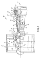
- FIG. 1 schematically illustrates a gas turbine engine 20.
- the gas turbine engine 20 is disclosed herein as a two-spool turbofan that generally incorporates a fan section 22, a compressor section 24, a combustor section 26 and a turbine section 28.
- Alternative engines might include an augmentor section among other systems or features.
- the fan section 22 drives air along a bypass flow path B in a bypass duct defined within a nacelle 15, while the compressor section 24 drives air along a core flow path C for compression and communication into the combustor section 26 then expansion through the turbine section 28.
- the exemplary engine 20 generally includes a low speed spool 30 and a high speed spool 32 mounted for rotation about an engine central longitudinal axis A relative to an engine static structure 36 via several bearing systems 31. It should be understood that various bearing systems 31 at various locations may alternatively or additionally be provided and the location of bearing systems 31 may be varied as appropriate to the application.
- the low speed spool 30 generally includes an inner shaft 34 that interconnects a fan 36, a first (or low) pressure compressor 38 and a first (or low) pressure turbine 39.
- the inner shaft 34 is connected to the fan 36 through a speed change mechanism, which in exemplary gas turbine engine 20 is illustrated as a geared architecture 45 to drive the fan 36 at a lower speed than the low speed spool 30.
- the high speed spool 32 includes an outer shaft 35 that interconnects a second (or high) pressure compressor 37 and a second (or high) pressure turbine 40.
- a combustor 42 is arranged in exemplary gas turbine 20 between the high pressure compressor 37 and the high pressure turbine 40.
- a mid-turbine frame 44 of the engine static structure 36 is arranged generally between the high pressure turbine 40 and the low pressure turbine 39.
- the mid-turbine frame 44 further supports bearing systems 31 in the turbine section 28.
- the inner shaft 34 and the outer shaft 35 are concentric and rotate via bearing systems 31 about the engine central longitudinal axis A which is collinear with their longitudinal axes.
- the core airflow is compressed by the low pressure compressor 38 then the high pressure compressor 37, mixed and burned with fuel in the combustor 42, then expanded over the high pressure turbine 40 and low pressure turbine 39.
- the mid-turbine frame 44 includes airfoils 46 which are in the core airflow path C.
- the turbines 39, 40 rotationally drive the respective low speed spool 30 and high speed spool 32 in response to the expansion.
- the engine 20 in one example is a high-bypass geared aircraft engine.
- the engine 20 bypass ratio is greater than about six (6), with an example embodiment being greater than about ten (10)
- the geared architecture 45 is an epicyclic gear train, such as a planetary gear system or other gear system, with a gear reduction ratio of greater than about 2.3
- the low pressure turbine 39 has a pressure ratio that is greater than about five.
- the engine 20 bypass ratio is greater than about ten (10:1)
- the fan diameter is significantly larger than that of the low pressure compressor 38
- the low pressure turbine 39 has a pressure ratio that is greater than about five 5:1.
- Low pressure turbine 39 pressure ratio is pressure measured prior to inlet of low pressure turbine 39 as related to the pressure at the outlet of the low pressure turbine 39 prior to an exhaust nozzle.
- the geared architecture 45 may be an epicycle gear train, such as a planetary gear system or other gear system, with a gear reduction ratio of greater than about 2.3:1. It should be understood, however, that the above parameters are only exemplary of one embodiment of a geared architecture engine and that the present disclosure is applicable to other gas turbine engines including direct drive turbofans.
- Each of the compressor section 24 and the turbine section 28 may include alternating rows of rotor assemblies and vane assemblies (shown schematically) that carry airfoils that extend into the core flow path C.
- the rotor assemblies can carry a plurality of rotating blades 25, while each vane assembly can carry a plurality of vanes 27 that extend into the core flow path C.
- the blades 25 create or extract energy (in the form of pressure) from the core airflow that is communicated through the gas turbine engine 20 along the core flow path C.
- the vanes 27 direct the core airflow to the blades 25 to either add or extract energy.
- Various components of the gas turbine engine 20, including but not limited to the airfoil and platform sections of the blades 25 and vanes 27 of the compressor section 24 and the turbine section 28, may be subjected to repetitive thermal cycling under widely ranging temperatures and pressures.
- the hardware of the turbine section 28 is particularly subjected to relatively extreme operating conditions. Therefore, some components may use dedicated internal cooling circuits to cool the parts during engine operation.
- This disclosure relates to gas turbine engine components having platform cooling core circuits.
- Figure 2 illustrates a rotor blade 60 that can be incorporated into a gas turbine engine, such as the compressor section 24 or the turbine section 28 of the gas turbine engine 20 of FIG. 1 .
- the rotor blade 60 may be part of a rotor assembly that includes a plurality of rotor blades circumferentially disposed about the engine centerline longitudinal axis A and configured to rotate to extract energy from the core airflow of the core flow path C.
- the rotor blade 60 includes a platform 62, an airfoil 64, and a root 66.
- the airfoil 64 extends from a gas path surface 68 of the platform 62 and the root 66 extends from a non-gas path surface 70 of the platform 62.
- the gas path surface 68 is exposed to the hot combustion gases of the core flow path C, whereas the non-gas path surface 70 is remote from the core flow path C.
- the root 66 is configured to attach the rotor blade 60 to a rotor assembly, such as within a slot formed in a rotor assembly.
- the root 66 includes a neck 86, which is, in various embodiments, an outer wall of the root 66.
- the platform 62 axially extends between a platform leading edge 72 and a platform trailing edge 74 and circumferentially extends between a first mate face 76 and a second mate face.
- the airfoil 64 axially extends between a leading edge 78 and a trailing edge 80 and circumferentially extends between a pressure side 82 and a suction side 84.
- the rotor blade 60 may include a cooling scheme 88 that includes one or more cooling core circuits (also known as cooling passages) and cooling holes 90 (shown as mate face cooling holes in this example) formed in the airfoil 64 and platform 62 of the rotor blade 60. Exemplary cooling schemes are described in greater detail below with respect to FIGS. 3 and 4 .
- the platform cooling core circuits may be formed through additive manufacturing.
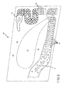
- FIG. 3 illustrates an exemplary cooling scheme 88 that can be incorporated into a rotor blade 60.
- the cooling scheme 88 includes a main body cooling core circuit 92 (i.e., a first cooling core circuit or cavity) and a platform cooling core circuit 94 (i.e., a second cooling core circuit or cavity).
- main body cooling core circuit 92 i.e., a first cooling core circuit or cavity
- platform cooling core circuit 94 i.e., a second cooling core circuit or cavity
- additional cooling core circuits may be formed inside of the rotor blade 60.
- the main body cooling core circuit 92 may extend through the root 66 and at least a portion of the airfoil 64.
- the main body cooling core circuit 92 can communicate the cooling fluid F, such as compressor bleed airflow, to cool the airfoil 64 and/or other sections of the rotor blade 60.
- the platform cooling core circuit 94 may be formed within the platform 62 and may be disposed adjacent to the pressure side 82 of the airfoil, the suction side 84 of the airfoil 64, or both (such as shown in FIG. 5 ).
- the platform cooling core circuit 94 may be a pocket formed near the platform leading edge 72 of the platform 62.
- the platform cooling core circuit 94 may be a pocket formed near the platform trailing edge 74.
- the platform cooling core circuit 94 is radially disposed between the gas path surface 68 and the non-gas path surface 70 and circumferentially disposed between the main body cooling core circuit 92 and the mate face 76, in various embodiments.
- the cooling scheme 88 may additionally include a plurality of cooling holes 90, 98 that are drilled or otherwise manufactured into the rotor blade 60.
- a first cooling hole 90 may extend between the mate face 76 and the platform cooling core circuit 94.
- the first cooling hole 90 may be referred to as a mate face cooling hole.
- a second cooling hole 98 may extend between the gas path surface 68 of the platform 62 and the platform cooling core circuit 94.
- the second cooling hole 98 may be referred to as a platform cooling hole. It should be understood that additional cooling holes could be disposed through both the platform 62 and the mate face 76.
- the platform cooling core circuit 94 may be fed with a portion of the cooling fluid F from the main body cooling core circuit 92.
- a passage 100 may fluidly connect the platform cooling core circuit 94 with the main body cooling core circuit 92.
- the cooling fluid F may circulate around plurality of one-wall pedestals 96 according to various embodiments prior to being expelled through at least one of the cooling holes 90 or 98.
- a first portion P1 of the cooling fluid F may be expelled through the first cooling hole 90 to provide a layer of film cooling air F2 at the mate face 76.
- the layer of film cooling air F2 expelled from the first cooling hole 90 discourages hot combustion gases from the core flow path C from ingesting into a mate face gap 102 that extends between the mate face 76 of the rotor blade 60 and a mate face 76-2 of a circumferentially adjacent rotor blade 60-2.
- a second portion P2 of the cooling fluid F may be expelled through the second cooling hole 98 to provide a layer of film cooling air F3 at the gas path surface 68 of the platform 62.
- the cooling fluid may be expelled at any location.
- the cooling fluid may be expelled, for example, onto the mate face and/or the gaspath surface. While the use of cooling holes has been described and illustrated, it is to be understood that cooling holes may be eliminated if the radial height of the platform cooling circuit will not permit cooling holes. The shorter the radial height of the platform cooling circuit, the better the heat transfer due to the higher velocity of the cooling fluid.
- FIG. 4 illustrates another cooling scheme 188 that may be incorporated into a rotor blade 60.
- Cooling scheme 188 includes a main body cooling core circuit 192 and a platform cooling core circuit 194.
- the platform cooling core circuit 194 may be fluidly isolated from the main body cooling core circuit 192. In other words, the platform cooling core circuit 194 is not fed by the main body cooling core circuit 192. Instead, the platform cooling core circuit 194 is fed with a cooling fluid F taken from a pocket 99 that extends radially inboard of the platform 62. In other words, the pocket 99 is located exterior from the rotor blade 60.
- the pocket 99 may extend between the neck 86 of the rotor blade 60 and a neck 86-2 of an adjacent rotor blade 60-2.
- Platform cooling core circuit 194 could be fed from any number of locations depending on the particular design and environment in which the component is to be utilized. A passage formed in the neck may connect the platform cooling core circuit 194 with the pocket 99.
- the cooling fluid is fed into the platform cooling core circuit 194, circulated over the one-wall pedestals 96, and may then be expelled through a cooling hole at a gas path surface 68 of the platform 62 and/or a mate face 76. There is a lower pressure drop in the cooling scheme 188, making it more difficult to achieve high heat transfer coefficients.
- the plurality of one-wall pedestals 96 are inside the platform cooling core circuit 94.
- the one-wall pedestals 96 may alter a flow characteristic of the cooling fluid circulated through the platform cooling core circuit 94 to create high heat transfer coefficients.
- the one-wall pedestals may be placed within the platform cooling core circuit 94 to manage stress, gas flow and heat transfer.
- the one-wall pedestals are referred to as “one-wall” pedestals as they extend from only one wall (the wall proximate the hot gas path surface (also referred to herein as “an outer endwall” or “first endwall” 97)) of the platform, and only partially extend from the outer endwall toward the opposing endwall of the platform (the wall proximate to the leakage air, i.e., "the inner endwall” or “second endwall” 101).
- the inner endwall 101 is proximate to the leakage air, it is not associated with as high of heat transfer coefficient as the outer endwall 97 that is proximate the hot gas path surface.
- Thermal loads and stresses on one-wall pedestals that extend from only the hot wall (the outer endwall) that is in proximity to the gaspath surface are significantly reduced because the hot and cold walls (the cold wall being the inner endwall 101 that is in proximity to the non-gaspath surface) are not connected, as would be the case with conventional two-wall pedestals.
- the one-wall pedestals that are connected only to the one hot wall do not benefit from a significant pressure drop for a high heat transfer coefficient.
- the one-wall pedestals extending from the one hot wall do not have to share the pressure drop that does exist with pedestals that extend from the cold wall where a high heat transfer coefficient is not beneficial.
- the heat transfer levels achieved are proportional to the number of one-wall pedestals used, assuming the one-wall pedestals are all substantially the same size. It is to be understood that the one-wall pedestals do not have to be the same size or shape.
- the plurality of one-wall pedestals may have a variety of shapes. In the depicted embodiment, the one-wall pedestals are rounded with a dome shape but the one-wall pedestals may have other shapes. Exemplary non-limiting shapes for the one-wall pedestals include a pedestal shape that is round, square, triangular, oval or racetrack.
- the one-wall pedestals may extend between about 50% to about 90% of the radial height of the platform cooling core circuit. While FIGS. 5 and 6 illustrate one-wall pedestals in particular locations of platform core circuits, it is to be understood that the one-wall pedestals may be on any part of the hot wall. It is also to be understood that while particular distributions of one-wall pedestals are illustrated in FIGS. 5 and 6 , the one-wall pedestals may be distributed in a manner other than as illustrated. For example, the one-wall pedestals may be distributed in a spaced apart manner or densely packed into a local area, no matter where the one-wall pedestals are located on the hot wall.
- a system 10 for cooling the airfoil platform of the gas turbine engine component comprises the plurality of one-wall pedestals inside the platform cooling core circuit of the airfoil platform, wherein the plurality of one-wall pedestals extend from only the first endwall 97, the first endwall 97 proximate the gas path surface 68 of the platform, and wherein the plurality of one-wall pedestals extend only partially between the first endwall 97 and the second endwall of the platform cooling core circuit, the second endwall 101 proximate a non-gas path surface of the platform.
- the plurality of one-wall pedestals extend from all or a portion of the first endwall.
- the one-wall pedestals enhance the heat transfer coefficient of the outer endwall from which they extend, but in doing so, uses only about one-third the pressure drop used by conventional two-wall pedestals.
- the one-wall pedestals provide high heat transfer coefficients without requiring a significant pressure drop.
- the cooling scheme 188 has limited pressure drop because of the abundance of seals in the portion of the turbine blade around where the platform cooling core circuit is located. Too much leakage in the portion of the turbine blade is a performance penalty and no leakage means there is ingestion of gas path air. Therefore, while there is a desire to use the leakage air to create high heat transfer coefficients to cool the airfoil platform, there is also a desire to tend to minimize leakage air to avoid a performance penalty. The pressure is therefore reduced to tend to minimize leakage, but still large enough to create the high heat transfer coefficients where needed.
- the one-wall pedestals may be inside the platform cooling core circuit located on the suction side of the airfoil, the pressure side of the airfoil, or both. The one-wall pedestals may be used throughout the entire platform cooling core circuit or in a portion thereof without limitation as to where the portion is located.
- Various embodiments enable increased heat transfer coefficients using a minimum pressure drop, thereby improving airfoil platform cooling particularly in cooling schemes where a pressure drop may be at a minimum.
- the pressure drop between the cooling core circuit inlet to the airfoil platform cooling core circuit with one-wall pedestals according to various embodiments and the cooling core circuit outlet therefrom is converted into high heat transfer coefficients, enabling improved airfoil platform cooling, particularly at the outer endwall that is exposed to the hot combustion gas.
- references to "one embodiment”, “an embodiment”, “various embodiments”, etc. indicate that the embodiment described may include a particular feature, structure, or characteristic, but every embodiment may not necessarily include the particular feature, structure, or characteristic. Moreover, such phrases are not necessarily referring to the same embodiment. Further, when a particular feature, structure, or characteristic is described in connection with an embodiment, it is submitted that it is within the knowledge of one skilled in the art to affect such feature, structure, or characteristic in connection with other embodiments whether or not explicitly described. After reading the description, it will be apparent to one skilled in the relevant art(s) how to implement the disclosure in alternative embodiments.
Landscapes
- Engineering & Computer Science (AREA)
- Mechanical Engineering (AREA)
- General Engineering & Computer Science (AREA)
- Physics & Mathematics (AREA)
- Thermal Sciences (AREA)
- Turbine Rotor Nozzle Sealing (AREA)
Applications Claiming Priority (1)
| Application Number | Priority Date | Filing Date | Title |
|---|---|---|---|
| US14/949,570 US20170145834A1 (en) | 2015-11-23 | 2015-11-23 | Airfoil platform cooling core circuits with one-wall heat transfer pedestals for a gas turbine engine component and systems for cooling an airfoil platform |
Publications (1)
| Publication Number | Publication Date |
|---|---|
| EP3170976A1 true EP3170976A1 (fr) | 2017-05-24 |
Family
ID=56939963
Family Applications (1)
| Application Number | Title | Priority Date | Filing Date |
|---|---|---|---|
| EP16189290.6A Withdrawn EP3170976A1 (fr) | 2015-11-23 | 2016-09-16 | Composant de moteur à turbine à gaz avec un circuit de refroidissement de plate-forme, système de refroidissement et moteur à turbine à gaz associés |
Country Status (2)
| Country | Link |
|---|---|
| US (1) | US20170145834A1 (fr) |
| EP (1) | EP3170976A1 (fr) |
Families Citing this family (4)
| Publication number | Priority date | Publication date | Assignee | Title |
|---|---|---|---|---|
| US10859295B2 (en) | 2016-04-13 | 2020-12-08 | ZeoThermal Technologies, LLC | Cooling and heating platform |
| US10422236B2 (en) * | 2017-08-03 | 2019-09-24 | General Electric Company | Turbine nozzle with stress-relieving pocket |
| US10787932B2 (en) * | 2018-07-13 | 2020-09-29 | Honeywell International Inc. | Turbine blade with dust tolerant cooling system |
| US10907480B2 (en) * | 2018-09-28 | 2021-02-02 | Raytheon Technologies Corporation | Ribbed pin fins |
Citations (4)
| Publication number | Priority date | Publication date | Assignee | Title |
|---|---|---|---|---|
| US6254333B1 (en) * | 1999-08-02 | 2001-07-03 | United Technologies Corporation | Method for forming a cooling passage and for cooling a turbine section of a rotary machine |
| US20130243575A1 (en) * | 2012-03-13 | 2013-09-19 | United Technologies Corporation | Cooling pedestal array |
| WO2015026430A1 (fr) * | 2013-08-20 | 2015-02-26 | United Technologies Corporation | Plaque de revêtement de plateforme de canalisation |
| WO2015057310A2 (fr) * | 2013-09-17 | 2015-04-23 | United Technologies Corporation | Noyau de refroidissement de plate-forme pour aube de rotor de turbine à gaz |
Family Cites Families (12)
| Publication number | Priority date | Publication date | Assignee | Title |
|---|---|---|---|---|
| US5197852A (en) * | 1990-05-31 | 1993-03-30 | General Electric Company | Nozzle band overhang cooling |
| GB2395987B (en) * | 2002-12-02 | 2005-12-21 | Alstom | Turbine blade with cooling bores |
| US7131817B2 (en) * | 2004-07-30 | 2006-11-07 | General Electric Company | Method and apparatus for cooling gas turbine engine rotor blades |
| US7597536B1 (en) * | 2006-06-14 | 2009-10-06 | Florida Turbine Technologies, Inc. | Turbine airfoil with de-coupled platform |
| US7766606B2 (en) * | 2006-08-17 | 2010-08-03 | Siemens Energy, Inc. | Turbine airfoil cooling system with platform cooling channels with diffusion slots |
| US7695247B1 (en) * | 2006-09-01 | 2010-04-13 | Florida Turbine Technologies, Inc. | Turbine blade platform with near-wall cooling |
| CH700319A1 (de) * | 2009-01-30 | 2010-07-30 | Alstom Technology Ltd | Gekühltes bauelement für eine gasturbine. |
| EP2256297B8 (fr) * | 2009-05-19 | 2012-10-03 | Alstom Technology Ltd | Aube de turbine à gaz dotée d'un refroidissement amélioré |
| US8851845B2 (en) * | 2010-11-17 | 2014-10-07 | General Electric Company | Turbomachine vane and method of cooling a turbomachine vane |
| US8870525B2 (en) * | 2011-11-04 | 2014-10-28 | General Electric Company | Bucket assembly for turbine system |
| US20140093388A1 (en) * | 2012-09-28 | 2014-04-03 | Solar Turbines Incorporated | Cooled turbine blade with leading edge flow deflection and division |
| US9810070B2 (en) * | 2013-05-15 | 2017-11-07 | General Electric Company | Turbine rotor blade for a turbine section of a gas turbine |
-
2015
- 2015-11-23 US US14/949,570 patent/US20170145834A1/en not_active Abandoned
-
2016
- 2016-09-16 EP EP16189290.6A patent/EP3170976A1/fr not_active Withdrawn
Patent Citations (4)
| Publication number | Priority date | Publication date | Assignee | Title |
|---|---|---|---|---|
| US6254333B1 (en) * | 1999-08-02 | 2001-07-03 | United Technologies Corporation | Method for forming a cooling passage and for cooling a turbine section of a rotary machine |
| US20130243575A1 (en) * | 2012-03-13 | 2013-09-19 | United Technologies Corporation | Cooling pedestal array |
| WO2015026430A1 (fr) * | 2013-08-20 | 2015-02-26 | United Technologies Corporation | Plaque de revêtement de plateforme de canalisation |
| WO2015057310A2 (fr) * | 2013-09-17 | 2015-04-23 | United Technologies Corporation | Noyau de refroidissement de plate-forme pour aube de rotor de turbine à gaz |
Also Published As
| Publication number | Publication date |
|---|---|
| US20170145834A1 (en) | 2017-05-25 |
Similar Documents
| Publication | Publication Date | Title |
|---|---|---|
| US10907481B2 (en) | Platform cooling core for a gas turbine engine rotor blade | |
| US9115590B2 (en) | Gas turbine engine airfoil cooling circuit | |
| US10502075B2 (en) | Platform cooling circuit for a gas turbine engine component | |
| EP3084136B1 (fr) | Aube rotorique et procédé associé de refroidissement d'une plateforme d'une aube rotorique | |
| US20140075947A1 (en) | Gas turbine engine component cooling circuit | |
| EP3477058A1 (fr) | Circuit de refroidissement de profil aérodynamique | |
| US10641105B2 (en) | Airfoil having forward flowing serpentine flow | |
| US20150354372A1 (en) | Gas turbine engine component with angled aperture impingement | |
| US20170145834A1 (en) | Airfoil platform cooling core circuits with one-wall heat transfer pedestals for a gas turbine engine component and systems for cooling an airfoil platform | |
| EP2885520B1 (fr) | Composant pour un moteur à turbine à gaz et procédé de refroidissement associé | |
| EP3567218B1 (fr) | Profil aérodynamique présentant un schéma amélioré de refroidissement de bord d'attaque et une meilleure résistance aux dommages | |
| US10513947B2 (en) | Adjustable flow split platform cooling for gas turbine engine | |
| US9453419B2 (en) | Gas turbine engine turbine blade tip cooling | |
| US10753210B2 (en) | Airfoil having improved cooling scheme | |
| US9790801B2 (en) | Gas turbine engine component having suction side cutback opening | |
| US11073023B2 (en) | Airfoil having improved throughflow cooling scheme and damage resistance | |
| US11434770B2 (en) | Tip cooling design |
Legal Events
| Date | Code | Title | Description |
|---|---|---|---|
| PUAI | Public reference made under article 153(3) epc to a published international application that has entered the european phase |
Free format text: ORIGINAL CODE: 0009012 |
|
| STAA | Information on the status of an ep patent application or granted ep patent |
Free format text: STATUS: THE APPLICATION HAS BEEN PUBLISHED |
|
| AK | Designated contracting states |
Kind code of ref document: A1 Designated state(s): AL AT BE BG CH CY CZ DE DK EE ES FI FR GB GR HR HU IE IS IT LI LT LU LV MC MK MT NL NO PL PT RO RS SE SI SK SM TR |
|
| AX | Request for extension of the european patent |
Extension state: BA ME |
|
| STAA | Information on the status of an ep patent application or granted ep patent |
Free format text: STATUS: REQUEST FOR EXAMINATION WAS MADE |
|
| 17P | Request for examination filed |
Effective date: 20171124 |
|
| RBV | Designated contracting states (corrected) |
Designated state(s): AL AT BE BG CH CY CZ DE DK EE ES FI FR GB GR HR HU IE IS IT LI LT LU LV MC MK MT NL NO PL PT RO RS SE SI SK SM TR |
|
| STAA | Information on the status of an ep patent application or granted ep patent |
Free format text: STATUS: EXAMINATION IS IN PROGRESS |
|
| 17Q | First examination report despatched |
Effective date: 20201118 |
|
| STAA | Information on the status of an ep patent application or granted ep patent |
Free format text: STATUS: THE APPLICATION HAS BEEN WITHDRAWN |
|
| 18W | Application withdrawn |
Effective date: 20210204 |