EP3171002A1 - Carter de soufflante pour turboréacteur à double flux - Google Patents
Carter de soufflante pour turboréacteur à double flux Download PDFInfo
- Publication number
- EP3171002A1 EP3171002A1 EP16196840.9A EP16196840A EP3171002A1 EP 3171002 A1 EP3171002 A1 EP 3171002A1 EP 16196840 A EP16196840 A EP 16196840A EP 3171002 A1 EP3171002 A1 EP 3171002A1
- Authority
- EP
- European Patent Office
- Prior art keywords
- fan case
- turbofan engine
- forward portion
- aft
- accordance
- Prior art date
- Legal status (The legal status is an assumption and is not a legal conclusion. Google has not performed a legal analysis and makes no representation as to the accuracy of the status listed.)
- Granted
Links
- 230000007423 decrease Effects 0.000 claims abstract description 11
- 230000008878 coupling Effects 0.000 claims description 11
- 238000010168 coupling process Methods 0.000 claims description 11
- 238000005859 coupling reaction Methods 0.000 claims description 11
- 238000010408 sweeping Methods 0.000 claims description 4
- 230000007704 transition Effects 0.000 claims description 4
- 238000011144 upstream manufacturing Methods 0.000 claims description 3
- 238000000034 method Methods 0.000 description 13
- 239000007789 gas Substances 0.000 description 4
- 230000000712 assembly Effects 0.000 description 2
- 238000000429 assembly Methods 0.000 description 2
- 230000008901 benefit Effects 0.000 description 2
- 239000000567 combustion gas Substances 0.000 description 2
- 239000000446 fuel Substances 0.000 description 2
- 230000008859 change Effects 0.000 description 1
- 239000002131 composite material Substances 0.000 description 1
- 230000003247 decreasing effect Effects 0.000 description 1
- 230000000694 effects Effects 0.000 description 1
- 230000006870 function Effects 0.000 description 1
- 238000004519 manufacturing process Methods 0.000 description 1
- 239000000463 material Substances 0.000 description 1
- 239000000203 mixture Substances 0.000 description 1
- 238000000926 separation method Methods 0.000 description 1
- 239000013585 weight reducing agent Substances 0.000 description 1
Images
Classifications
-
- F—MECHANICAL ENGINEERING; LIGHTING; HEATING; WEAPONS; BLASTING
- F02—COMBUSTION ENGINES; HOT-GAS OR COMBUSTION-PRODUCT ENGINE PLANTS
- F02C—GAS-TURBINE PLANTS; AIR INTAKES FOR JET-PROPULSION PLANTS; CONTROLLING FUEL SUPPLY IN AIR-BREATHING JET-PROPULSION PLANTS
- F02C7/00—Features, components parts, details or accessories, not provided for in, or of interest apart form groups F02C1/00 - F02C6/00; Air intakes for jet-propulsion plants
-
- F—MECHANICAL ENGINEERING; LIGHTING; HEATING; WEAPONS; BLASTING
- F02—COMBUSTION ENGINES; HOT-GAS OR COMBUSTION-PRODUCT ENGINE PLANTS
- F02C—GAS-TURBINE PLANTS; AIR INTAKES FOR JET-PROPULSION PLANTS; CONTROLLING FUEL SUPPLY IN AIR-BREATHING JET-PROPULSION PLANTS
- F02C7/00—Features, components parts, details or accessories, not provided for in, or of interest apart form groups F02C1/00 - F02C6/00; Air intakes for jet-propulsion plants
- F02C7/04—Air intakes for gas-turbine plants or jet-propulsion plants
- F02C7/042—Air intakes for gas-turbine plants or jet-propulsion plants having variable geometry
-
- F—MECHANICAL ENGINEERING; LIGHTING; HEATING; WEAPONS; BLASTING
- F02—COMBUSTION ENGINES; HOT-GAS OR COMBUSTION-PRODUCT ENGINE PLANTS
- F02K—JET-PROPULSION PLANTS
- F02K3/00—Plants including a gas turbine driving a compressor or a ducted fan
- F02K3/02—Plants including a gas turbine driving a compressor or a ducted fan in which part of the working fluid by-passes the turbine and combustion chamber
- F02K3/04—Plants including a gas turbine driving a compressor or a ducted fan in which part of the working fluid by-passes the turbine and combustion chamber the plant including ducted fans, i.e. fans with high volume, low pressure outputs, for augmenting the jet thrust, e.g. of double-flow type
- F02K3/068—Plants including a gas turbine driving a compressor or a ducted fan in which part of the working fluid by-passes the turbine and combustion chamber the plant including ducted fans, i.e. fans with high volume, low pressure outputs, for augmenting the jet thrust, e.g. of double-flow type being characterised by a short axial length relative to the diameter
-
- B—PERFORMING OPERATIONS; TRANSPORTING
- B64—AIRCRAFT; AVIATION; COSMONAUTICS
- B64D—EQUIPMENT FOR FITTING IN OR TO AIRCRAFT; FLIGHT SUITS; PARACHUTES; ARRANGEMENT OR MOUNTING OF POWER PLANTS OR PROPULSION TRANSMISSIONS IN AIRCRAFT
- B64D29/00—Power-plant nacelles, fairings or cowlings
-
- B—PERFORMING OPERATIONS; TRANSPORTING
- B64—AIRCRAFT; AVIATION; COSMONAUTICS
- B64D—EQUIPMENT FOR FITTING IN OR TO AIRCRAFT; FLIGHT SUITS; PARACHUTES; ARRANGEMENT OR MOUNTING OF POWER PLANTS OR PROPULSION TRANSMISSIONS IN AIRCRAFT
- B64D33/00—Arrangement in aircraft of power plant parts or auxiliaries not otherwise provided for
- B64D33/02—Arrangement in aircraft of power plant parts or auxiliaries not otherwise provided for of combustion air intakes
-
- F—MECHANICAL ENGINEERING; LIGHTING; HEATING; WEAPONS; BLASTING
- F02—COMBUSTION ENGINES; HOT-GAS OR COMBUSTION-PRODUCT ENGINE PLANTS
- F02C—GAS-TURBINE PLANTS; AIR INTAKES FOR JET-PROPULSION PLANTS; CONTROLLING FUEL SUPPLY IN AIR-BREATHING JET-PROPULSION PLANTS
- F02C7/00—Features, components parts, details or accessories, not provided for in, or of interest apart form groups F02C1/00 - F02C6/00; Air intakes for jet-propulsion plants
- F02C7/04—Air intakes for gas-turbine plants or jet-propulsion plants
- F02C7/045—Air intakes for gas-turbine plants or jet-propulsion plants having provisions for noise suppression
-
- F—MECHANICAL ENGINEERING; LIGHTING; HEATING; WEAPONS; BLASTING
- F02—COMBUSTION ENGINES; HOT-GAS OR COMBUSTION-PRODUCT ENGINE PLANTS
- F02K—JET-PROPULSION PLANTS
- F02K3/00—Plants including a gas turbine driving a compressor or a ducted fan
- F02K3/02—Plants including a gas turbine driving a compressor or a ducted fan in which part of the working fluid by-passes the turbine and combustion chamber
- F02K3/04—Plants including a gas turbine driving a compressor or a ducted fan in which part of the working fluid by-passes the turbine and combustion chamber the plant including ducted fans, i.e. fans with high volume, low pressure outputs, for augmenting the jet thrust, e.g. of double-flow type
- F02K3/06—Plants including a gas turbine driving a compressor or a ducted fan in which part of the working fluid by-passes the turbine and combustion chamber the plant including ducted fans, i.e. fans with high volume, low pressure outputs, for augmenting the jet thrust, e.g. of double-flow type with front fan
-
- B—PERFORMING OPERATIONS; TRANSPORTING
- B64—AIRCRAFT; AVIATION; COSMONAUTICS
- B64D—EQUIPMENT FOR FITTING IN OR TO AIRCRAFT; FLIGHT SUITS; PARACHUTES; ARRANGEMENT OR MOUNTING OF POWER PLANTS OR PROPULSION TRANSMISSIONS IN AIRCRAFT
- B64D33/00—Arrangement in aircraft of power plant parts or auxiliaries not otherwise provided for
- B64D33/02—Arrangement in aircraft of power plant parts or auxiliaries not otherwise provided for of combustion air intakes
- B64D2033/0206—Arrangement in aircraft of power plant parts or auxiliaries not otherwise provided for of combustion air intakes comprising noise reduction means, e.g. acoustic liners
-
- F—MECHANICAL ENGINEERING; LIGHTING; HEATING; WEAPONS; BLASTING
- F05—INDEXING SCHEMES RELATING TO ENGINES OR PUMPS IN VARIOUS SUBCLASSES OF CLASSES F01-F04
- F05D—INDEXING SCHEME FOR ASPECTS RELATING TO NON-POSITIVE-DISPLACEMENT MACHINES OR ENGINES, GAS-TURBINES OR JET-PROPULSION PLANTS
- F05D2230/00—Manufacture
- F05D2230/70—Disassembly methods
-
- F—MECHANICAL ENGINEERING; LIGHTING; HEATING; WEAPONS; BLASTING
- F05—INDEXING SCHEMES RELATING TO ENGINES OR PUMPS IN VARIOUS SUBCLASSES OF CLASSES F01-F04
- F05D—INDEXING SCHEME FOR ASPECTS RELATING TO NON-POSITIVE-DISPLACEMENT MACHINES OR ENGINES, GAS-TURBINES OR JET-PROPULSION PLANTS
- F05D2250/00—Geometry
- F05D2250/30—Arrangement of components
- F05D2250/31—Arrangement of components according to the direction of their main axis or their axis of rotation
- F05D2250/314—Arrangement of components according to the direction of their main axis or their axis of rotation the axes being inclined in relation to each other
-
- F—MECHANICAL ENGINEERING; LIGHTING; HEATING; WEAPONS; BLASTING
- F05—INDEXING SCHEMES RELATING TO ENGINES OR PUMPS IN VARIOUS SUBCLASSES OF CLASSES F01-F04
- F05D—INDEXING SCHEME FOR ASPECTS RELATING TO NON-POSITIVE-DISPLACEMENT MACHINES OR ENGINES, GAS-TURBINES OR JET-PROPULSION PLANTS
- F05D2260/00—Function
- F05D2260/96—Preventing, counteracting or reducing vibration or noise
-
- Y—GENERAL TAGGING OF NEW TECHNOLOGICAL DEVELOPMENTS; GENERAL TAGGING OF CROSS-SECTIONAL TECHNOLOGIES SPANNING OVER SEVERAL SECTIONS OF THE IPC; TECHNICAL SUBJECTS COVERED BY FORMER USPC CROSS-REFERENCE ART COLLECTIONS [XRACs] AND DIGESTS
- Y02—TECHNOLOGIES OR APPLICATIONS FOR MITIGATION OR ADAPTATION AGAINST CLIMATE CHANGE
- Y02T—CLIMATE CHANGE MITIGATION TECHNOLOGIES RELATED TO TRANSPORTATION
- Y02T50/00—Aeronautics or air transport
- Y02T50/60—Efficient propulsion technologies, e.g. for aircraft
Definitions
- the field of the disclosure relates generally to turbofan engines and, more particularly, to an elongated fan case for use in a turbofan engine.
- At least some known gas turbine engines include a fan, a core engine, and a power turbine.
- the core engine includes at least one compressor, a combustor, and a high-pressure turbine coupled together in a serial flow relationship. More specifically, the compressor and high-pressure turbine are coupled through a first drive shaft to form a high-pressure rotor assembly. Air entering the core engine is mixed with fuel and ignited to form a high energy gas stream. The high energy gas stream flows through the high-pressure turbine to rotatably drive the high-pressure turbine such that the shaft rotatably drives the compressor. The gas stream expands as it flows through a power or low-pressure turbine positioned aft of the high-pressure turbine.
- the low-pressure turbine includes a rotor assembly having a fan coupled to a second drive shaft. The low-pressure turbine rotatably drives the fan through the second drive shaft.
- a drooped inlet which is angled relative to a centerline of the turbofan engine.
- the drooped inlet is incorporated to facilitate matching the airflow upwash angle in front of the wing of an aircraft, in which the turbofan engine is attached, when the aircraft is traveling at cruise conditions.
- the angle of the drooped inlet is typically achieved by contouring the inner flow surface of a nacelle housing of the turbofan engine.
- the drooped inlet is typically formed from a series of components such as a lipskin, inner and outer bondments or barrels having acoustic lining incorporated therein, and forward and aft bulkheads.
- space within the drooped inlet for receiving acoustic lining is becoming increasingly limited as nacelle housings are shortened to increase weight reduction and reduce drag.
- a fan case for use in a turbofan engine includes an aft portion that is substantially cylindrical and axi-symmetric about a centerline of the turbofan engine, and a forward portion extending from the aft portion.
- a cross-sectional shape of the forward portion progressively decreases in radial size as the forward portion extends from the aft portion.
- a turbofan engine in another aspect, includes a nacelle housing, and a fan case coupled to the nacelle housing.
- the fan case includes an aft portion that is substantially cylindrical and axi-symmetric about a centerline of the turbofan engine, and a forward portion extending from the aft portion. A cross-sectional shape of the forward portion progressively decreases in radial size as the forward portion extends from the aft portion.
- a method of assembling a turbofan engine includes providing a fan case that includes an aft portion that is substantially cylindrical and axi-symmetric about a centerline of the turbofan engine, and a forward portion extending from the aft portion.
- a cross-sectional shape of the forward portion progressively decreases in radial size as the forward portion extends from the aft portion.
- Approximating language may be applied to modify any quantitative representation that could permissibly vary without resulting in a change in the basic function to which it is related. Accordingly, a value modified by a term or terms, such as “about”, “approximately”, and “substantially”, are not to be limited to the precise value specified. In at least some instances, the approximating language may correspond to the precision of an instrument for measuring the value.
- range limitations may be combined and/or interchanged, such ranges are identified and include all the sub-ranges contained therein unless context or language indicates otherwise.
- the terms “axial” and “axially” refer to directions and orientations that extend substantially parallel to a centerline of the turbine engine.
- the terms “radial” and “radially” refer to directions and orientations that extend substantially perpendicular to the centerline of the turbine engine.
- the terms “circumferential” and “circumferentially” refer to directions and orientations that extend arcuately about the centerline of the turbine engine.
- Embodiments of the present disclosure relate to turbine engines, such as turbofans, and methods of manufacturing thereof. More specifically, the turbofan engines described herein include an elongated fan case including a forward portion having a radially inner surface that defines a drooped inlet of the turbofan engine. Defining the drooped inlet of the turbofan engine with the inner flow surface of the fan case facilitates eliminating components from a nacelle housing coupled to the fan case that once defined the drooped inlet. The fan case inlet is thus more simplified and more symmetrical.
- the length of the nacelle housing is reduced, thereby enabling a smaller inner barrel with a reduced amount of acoustic treatment to be used, while also reducing the overall weight of the turbofan engine.
- elongating the fan case along the axial centerline of the turbofan engine enables a continuous sheet of acoustic lining to be positioned therein, thereby improving the acoustic dissipation of noise generated by the turbofan engine.
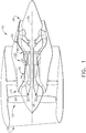
- FIG. 1 is a schematic illustration of an exemplary turbofan engine 10 including a fan assembly 12, a low pressure or booster compressor 14, a high-pressure compressor 16, and a combustor assembly 18.
- Fan assembly 12, booster compressor 14, high-pressure compressor 16, and combustor assembly 18 are coupled in flow communication.
- Turbofan engine 10 also includes a high-pressure turbine 20 coupled in flow communication with combustor assembly 18 and a low-pressure turbine 22.
- Fan assembly 12 includes an array of fan blades 24 extending radially outward from a rotor disk 26.
- Low-pressure turbine 22 is coupled to fan assembly 12 and booster compressor 14 via a first drive shaft 28, and high-pressure turbine 20 is coupled to high-pressure compressor 16 via a second drive shaft 30.
- Turbofan engine 10 has an intake 32 and an exhaust 34.
- Turbofan engine 10 further includes a centerline 36 about which fan assembly 12, booster compressor 14, high-pressure compressor 16, and turbine assemblies 20 and 22 rotate.
- turbofan engine 10 In operation, air entering turbofan engine 10 through intake 32 is channeled through fan assembly 12 towards booster compressor 14. Compressed air is discharged from booster compressor 14 towards high-pressure compressor 16. Highly compressed air is channeled from high-pressure compressor 16 towards combustor assembly 18, mixed with fuel, and the mixture is combusted within combustor assembly 18. High temperature combustion gas generated by combustor assembly 18 is channeled towards turbine assemblies 20 and 22. Combustion gas is subsequently discharged from turbofan engine 10 via exhaust 34.
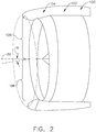
- FIG. 2 is a perspective view of an exemplary fan case 100 that may be used in turbofan engine 10 (shown in FIG. 1 ).
- fan case 100 includes an aft portion 102 and a forward portion 104 extending from aft portion 102.
- Aft portion 102 is substantially cylindrical and axi-symmetric about centerline 36 of turbofan engine 10 (each shown in FIG. 1 ), and a cross-sectional shape of forward portion 104 progressively decreases in radial size as forward portion 104 extends from aft portion 102. More specifically, forward portion 104 is shaped to define a drooped inlet of turbofan engine 10, as will be described in more detail below.
- forward portion 104 includes a first arcuate portion 106 and a second arcuate portion 108.
- First arcuate portion 106 is defined as a circumferential section of forward portion 104 extending between about the 270° and 90° marks of forward portion 104 when turbofan engine 10 is viewed axially along centerline 36.
- second arcuate portion 108 is defined as a circumferential section of forward portion 104 extending between about the 90° and 270° marks of forward portion 104 when turbofan engine 10 is viewed axially along centerline 36.
- first arcuate portion 106 is generally defined as an upper portion of forward portion 104
- second arcuate portion 108 is generally defined as a lower portion of forward portion 104.
- first arcuate portion 106 extends a greater distance from aft portion 102 than second arcuate portion 108 such that a droop angle ⁇ is defined at intake 32 of turbofan engine 10.
- droop angle ⁇ is less than about 10 degrees relative to a centerline of fan case 100, which generally corresponds to centerline 36 of turbofan engine 10.
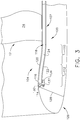
- FIG. 3 is a cross-sectional side view illustration of an exemplary portion of fan case 100.
- forward portion 104 progressively decreases in radial size as forward portion 104 extends from aft portion 102. More specifically, when viewed from interior of fan case 100, forward portion 104 has a sweeping profile that progressively transitions from a concave shape to a convex shape as forward portion 104 extends from aft portion 102.
- forward portion 104 includes a concave portion 110 extending from aft portion 102, and a convex portion 112 extending from concave portion 110 towards a leading edge 114 of forward portion 104. As such, flow separation at a flow surface 116 of fan case 100 of a flow of air channeled towards fan blades 24 is reduced.
- Fan case 100 also includes an interior cavity 118 defined between a radially inner wall 120 and a radially outer wall 122.
- elongating fan case 100 relative to centerline 36 (shown in FIG. 1 ) enables a sheet 124 of acoustic lining to extend continuously between aft portion 102 and forward portion 104.
- An exemplary acoustic lining material includes, but is not limited to, a honeycomb structure formed from composite material.
- Extending sheet 124 of acoustic lining continuously between aft portion 102 and forward portion 104 facilitates improving the acoustic dissipation of noise generated by turbofan engine 10, when compared to the acoustic dissipation capable of being achieved by truncated sheets of acoustic lining.
- sheet 124 of acoustic lining is selectively removable from interior cavity 118 to facilitate removal of individual fan blades 24 from turbofan engine 10.
- an inlet structure incorporating a drooped inlet was selectively removable from the turbofan engine to enable individual fan blades to be removed therefrom.
- Progressively decreasing the radial size of forward portion 104 facilitates restricting the axial movement of fan blades 24 towards intake 32.
- sheet 124 of acoustic lining is selectively removable from interior cavity 118 to reduce the radial height of fan case 100, and to enable fan blades to be translated axially towards intake 32.
- turbofan engine 10 includes a nacelle housing 126, and fan case 100 is coupled to nacelle housing 126.
- Nacelle housing 126 includes a forward bulkhead 128 positioned therein.
- forward portion 104 of fan case 100 is capable of extending from aft portion 102 towards forward bulkhead 128.
- leading edge 114 of forward portion 104 is coupled to forward bulkhead 128.
- forward portion 104 of fan case 100 is positioned upstream of fan assembly 12.
- Nacelle housing 126 also includes a first attachment flange 130 for coupling to a second attachment flange 132 positioned at leading edge 114 of forward portion 104. More specifically, first attachment flange 130 extends radially outward from a radially inner wall 120 of nacelle housing 126 for coupling to second attachment flange 132. Alternatively, first attachment flange 130 extends from forward bulkhead 128 for coupling to second attachment flange 132. Coupling first attachment flange 130 to second attachment flange 132 enables a fastener 134 to be extended therethrough, thereby securing fan case 100 to nacelle housing 126. Moreover, in one embodiment, first and second attachment flanges 130 and 132 extend obliquely relative to centerline 36 such that they are aligned with droop angle ⁇ .
- An exemplary technical effect of the methods, systems, and apparatus described herein includes at least one of: (a) reducing the length to diameter ratio of a turbofan engine; (b) reducing the overall weight of a turbofan engine; and (c) improving the acoustic dissipation capabilities of acoustic lining positioned within a turbofan engine.
- fan case for use in a turbofan engine are described above in detail.
- the fan case is not limited to the specific embodiments described herein, but rather, components of systems and/or steps of the methods may be utilized independently and separately from other components and/or steps described herein.
- the fan case may also be used in combination with other systems that would benefit from reducing the length of a nacelle housing, and are not limited to practice with only the systems and methods as described herein. Rather, the exemplary embodiment can be implemented and utilized in connection with many other aerospace applications.
Landscapes
- Engineering & Computer Science (AREA)
- Chemical & Material Sciences (AREA)
- Combustion & Propulsion (AREA)
- Mechanical Engineering (AREA)
- General Engineering & Computer Science (AREA)
- Aviation & Aerospace Engineering (AREA)
- Physics & Mathematics (AREA)
- Geometry (AREA)
- Structures Of Non-Positive Displacement Pumps (AREA)
Applications Claiming Priority (1)
| Application Number | Priority Date | Filing Date | Title |
|---|---|---|---|
| US14/946,404 US10830136B2 (en) | 2015-11-19 | 2015-11-19 | Fan case for use in a turbofan engine, and method of assembling a turbofan engine |
Publications (2)
| Publication Number | Publication Date |
|---|---|
| EP3171002A1 true EP3171002A1 (fr) | 2017-05-24 |
| EP3171002B1 EP3171002B1 (fr) | 2018-10-03 |
Family
ID=57249702
Family Applications (1)
| Application Number | Title | Priority Date | Filing Date |
|---|---|---|---|
| EP16196840.9A Not-in-force EP3171002B1 (fr) | 2015-11-19 | 2016-11-02 | Carter de soufflante pour turboréacteur à double flux |
Country Status (6)
| Country | Link |
|---|---|
| US (1) | US10830136B2 (fr) |
| EP (1) | EP3171002B1 (fr) |
| JP (1) | JP2017115857A (fr) |
| CN (1) | CN107035525B (fr) |
| BR (1) | BR102016026838A2 (fr) |
| CA (1) | CA2948251A1 (fr) |
Cited By (1)
| Publication number | Priority date | Publication date | Assignee | Title |
|---|---|---|---|---|
| EP3828400A1 (fr) * | 2019-11-29 | 2021-06-02 | Rolls-Royce plc | Nacelle pour moteur de turbine à gaz |
Families Citing this family (6)
| Publication number | Priority date | Publication date | Assignee | Title |
|---|---|---|---|---|
| US20170175626A1 (en) * | 2015-12-18 | 2017-06-22 | United Technologies Corporation | Gas turbine engine with minimized inlet distortion |
| US10544676B2 (en) | 2016-02-03 | 2020-01-28 | General Electric Company | Situ gas turbine prevention of crack growth progression |
| US10190442B2 (en) | 2016-03-22 | 2019-01-29 | General Electric Company | Gas turbine in situ inflatable bladders for on-wing repair |
| US12435666B1 (en) | 2024-10-09 | 2025-10-07 | General Electric Company | Turbine engine having a variable engine intake system |
| US12442333B1 (en) | 2024-10-09 | 2025-10-14 | General Electric Company | Turbine engine having a variable engine intake system |
| US12529335B1 (en) | 2024-10-09 | 2026-01-20 | General Electric Company | Turbine engine having a variable engine intake system |
Citations (6)
| Publication number | Priority date | Publication date | Assignee | Title |
|---|---|---|---|---|
| US4220171A (en) * | 1979-05-14 | 1980-09-02 | The United States Of America As Represented By The Administrator Of The National Aeronautics And Space Administration | Curved centerline air intake for a gas turbine engine |
| US5169288A (en) * | 1991-09-06 | 1992-12-08 | General Electric Company | Low noise fan assembly |
| US5915403A (en) * | 1998-04-14 | 1999-06-29 | The Boeing Company | Biplanar scarfed nacelle inlet |
| US20050082112A1 (en) * | 2003-10-17 | 2005-04-21 | Harrison Geoffrey E. | Annular acoustic panel |
| EP2241504A2 (fr) * | 2009-04-14 | 2010-10-20 | Rohr, Inc. | Nacelle pour moteur d'aéronef |
| US20130283821A1 (en) * | 2012-04-30 | 2013-10-31 | Jonathan Gilson | Gas turbine engine and nacelle noise attenuation structure |
Family Cites Families (17)
| Publication number | Priority date | Publication date | Assignee | Title |
|---|---|---|---|---|
| US3933327A (en) * | 1974-08-30 | 1976-01-20 | Rohr Industries, Inc. | Aircraft anti-icing plenum |
| US4484856A (en) * | 1981-12-21 | 1984-11-27 | United Technologies Corporation | Containment structure |
| DE3271806D1 (en) | 1982-12-27 | 1986-07-24 | Boeing Co | Inlet cowl attachment for jet engine |
| GB2159886B (en) | 1984-06-07 | 1988-01-27 | Rolls Royce | Fan duct casing |
| US6206631B1 (en) | 1999-09-07 | 2001-03-27 | General Electric Company | Turbomachine fan casing with dual-wall blade containment structure |
| US6371411B1 (en) * | 1999-11-23 | 2002-04-16 | The Boeing Company | Method and apparatus for aircraft inlet ice protection |
| GB2407343B (en) * | 2003-10-22 | 2006-04-19 | Rolls Royce Plc | An acoustic liner for a gas turbine engine casing |
| GB0813821D0 (en) | 2008-07-29 | 2008-09-03 | Rolls Royce Plc | A fan casing for a gas turbine engine |
| GB0813820D0 (en) | 2008-07-29 | 2008-09-03 | Rolls Royce Plc | A fan casing for a gas turbine engine |
| FR2935017B1 (fr) * | 2008-08-13 | 2012-11-02 | Snecma | Paroi interne d'une nacelle de turbomachine |
| US8092169B2 (en) | 2008-09-16 | 2012-01-10 | United Technologies Corporation | Integrated inlet fan case |
| FR2965861B1 (fr) | 2010-10-11 | 2014-05-09 | Aircelle Sa | Dispositif de liaison d'un cadre avant d'inverseur de poussee a un carter de soufflante, et nacelle incorporant un tel dispositif |
| GB201103583D0 (en) | 2011-03-03 | 2011-04-13 | Rolls Royce Plc | Fan casing for a turbofan engine |
| FR2988778B1 (fr) | 2012-03-29 | 2014-03-21 | Aircelle Sa | Structure d'entree d'air de nacelle de turboreacteur de type laminaire |
| US9534505B2 (en) | 2012-07-23 | 2017-01-03 | United Technologies Corporation | Integrated nacelle inlet and metallic fan containment case |
| US9623976B2 (en) | 2012-07-25 | 2017-04-18 | Rohr, Inc. | Nacelle for a high bypass ratio engine with multiple flow paths |
| US10385870B2 (en) | 2013-12-17 | 2019-08-20 | General Electric Company | Composite fan inlet blade containment |
-
2015
- 2015-11-19 US US14/946,404 patent/US10830136B2/en active Active
-
2016
- 2016-11-02 EP EP16196840.9A patent/EP3171002B1/fr not_active Not-in-force
- 2016-11-14 JP JP2016221097A patent/JP2017115857A/ja active Pending
- 2016-11-14 CA CA2948251A patent/CA2948251A1/fr not_active Abandoned
- 2016-11-17 BR BR102016026838-9A patent/BR102016026838A2/pt not_active Application Discontinuation
- 2016-11-18 CN CN201611016288.7A patent/CN107035525B/zh active Active
Patent Citations (6)
| Publication number | Priority date | Publication date | Assignee | Title |
|---|---|---|---|---|
| US4220171A (en) * | 1979-05-14 | 1980-09-02 | The United States Of America As Represented By The Administrator Of The National Aeronautics And Space Administration | Curved centerline air intake for a gas turbine engine |
| US5169288A (en) * | 1991-09-06 | 1992-12-08 | General Electric Company | Low noise fan assembly |
| US5915403A (en) * | 1998-04-14 | 1999-06-29 | The Boeing Company | Biplanar scarfed nacelle inlet |
| US20050082112A1 (en) * | 2003-10-17 | 2005-04-21 | Harrison Geoffrey E. | Annular acoustic panel |
| EP2241504A2 (fr) * | 2009-04-14 | 2010-10-20 | Rohr, Inc. | Nacelle pour moteur d'aéronef |
| US20130283821A1 (en) * | 2012-04-30 | 2013-10-31 | Jonathan Gilson | Gas turbine engine and nacelle noise attenuation structure |
Cited By (2)
| Publication number | Priority date | Publication date | Assignee | Title |
|---|---|---|---|---|
| EP3828400A1 (fr) * | 2019-11-29 | 2021-06-02 | Rolls-Royce plc | Nacelle pour moteur de turbine à gaz |
| US11313241B2 (en) | 2019-11-29 | 2022-04-26 | Rolls-Royce Plc | Nacelle for a gas turbine engine |
Also Published As
| Publication number | Publication date |
|---|---|
| US10830136B2 (en) | 2020-11-10 |
| CN107035525A (zh) | 2017-08-11 |
| CA2948251A1 (fr) | 2017-05-19 |
| BR102016026838A2 (pt) | 2017-07-18 |
| US20170145916A1 (en) | 2017-05-25 |
| JP2017115857A (ja) | 2017-06-29 |
| CN107035525B (zh) | 2019-02-22 |
| EP3171002B1 (fr) | 2018-10-03 |
Similar Documents
| Publication | Publication Date | Title |
|---|---|---|
| EP3171002B1 (fr) | Carter de soufflante pour turboréacteur à double flux | |
| EP3187712B1 (fr) | Admission courte de nacelle | |
| EP3034796A1 (fr) | Moteur à turbine et son procédé d'assemblage | |
| US20160160647A1 (en) | Turbine engine assembly and method of manufacturing | |
| EP3239511A1 (fr) | Ensemble de turboréacteur et procédé d'assemblage | |
| US10308368B2 (en) | Turbofan engine and method of reducing air flow separation therein | |
| EP3187722A1 (fr) | Admission courte de nacelle pour l'enlèvement de pale de ventilateur | |
| US10267161B2 (en) | Gas turbine engine with fillet film holes | |
| CN108952823A (zh) | 用于前缘辅助叶片的方法和系统 | |
| CN108691810B (zh) | 涡轮发动机容纳组件及其制造方法 | |
| EP3184755A2 (fr) | Collecteur destiné à être utilisé dans un système de réglage de jeu et procédé de fabrication | |
| US20210277802A1 (en) | Fan case for a gas turbine engine | |
| EP3170982A1 (fr) | Ensemble rotor pour utilisation dans turboréacteur à double flux et son procédé d'assemblage | |
| EP3153658B1 (fr) | Système de protection de tourbillonnement | |
| CN117386464A (zh) | 用于在涡轮发动机容纳组件中使用的背板及其形成方法 | |
| CN108730034B (zh) | 涡轮发动机和用于涡轮发动机中的容纳组件 | |
| US10662813B2 (en) | Turbine engine and containment assembly for use in a turbine engine | |
| US20110011058A1 (en) | Turbofan engine | |
| US10047763B2 (en) | Rotor assembly for use in a turbofan engine and method of assembling | |
| EP3170973A1 (fr) | Écoulement de l'air dans une turbomachine |
Legal Events
| Date | Code | Title | Description |
|---|---|---|---|
| PUAI | Public reference made under article 153(3) epc to a published international application that has entered the european phase |
Free format text: ORIGINAL CODE: 0009012 |
|
| AK | Designated contracting states |
Kind code of ref document: A1 Designated state(s): AL AT BE BG CH CY CZ DE DK EE ES FI FR GB GR HR HU IE IS IT LI LT LU LV MC MK MT NL NO PL PT RO RS SE SI SK SM TR |
|
| AX | Request for extension of the european patent |
Extension state: BA ME |
|
| 17P | Request for examination filed |
Effective date: 20171124 |
|
| RBV | Designated contracting states (corrected) |
Designated state(s): AL AT BE BG CH CY CZ DE DK EE ES FI FR GB GR HR HU IE IS IT LI LT LU LV MC MK MT NL NO PL PT RO RS SE SI SK SM TR |
|
| GRAP | Despatch of communication of intention to grant a patent |
Free format text: ORIGINAL CODE: EPIDOSNIGR1 |
|
| INTG | Intention to grant announced |
Effective date: 20180531 |
|
| GRAS | Grant fee paid |
Free format text: ORIGINAL CODE: EPIDOSNIGR3 |
|
| GRAA | (expected) grant |
Free format text: ORIGINAL CODE: 0009210 |
|
| AK | Designated contracting states |
Kind code of ref document: B1 Designated state(s): AL AT BE BG CH CY CZ DE DK EE ES FI FR GB GR HR HU IE IS IT LI LT LU LV MC MK MT NL NO PL PT RO RS SE SI SK SM TR |
|
| REG | Reference to a national code |
Ref country code: GB Ref legal event code: FG4D |
|
| REG | Reference to a national code |
Ref country code: CH Ref legal event code: EP Ref country code: AT Ref legal event code: REF Ref document number: 1048860 Country of ref document: AT Kind code of ref document: T Effective date: 20181015 |
|
| REG | Reference to a national code |
Ref country code: IE Ref legal event code: FG4D Ref country code: DE Ref legal event code: R096 Ref document number: 602016006205 Country of ref document: DE |
|
| REG | Reference to a national code |
Ref country code: NL Ref legal event code: MP Effective date: 20181003 |
|
| REG | Reference to a national code |
Ref country code: LT Ref legal event code: MG4D |
|
| REG | Reference to a national code |
Ref country code: AT Ref legal event code: MK05 Ref document number: 1048860 Country of ref document: AT Kind code of ref document: T Effective date: 20181003 |
|
| PG25 | Lapsed in a contracting state [announced via postgrant information from national office to epo] |
Ref country code: NL Free format text: LAPSE BECAUSE OF FAILURE TO SUBMIT A TRANSLATION OF THE DESCRIPTION OR TO PAY THE FEE WITHIN THE PRESCRIBED TIME-LIMIT Effective date: 20181003 |
|
| PG25 | Lapsed in a contracting state [announced via postgrant information from national office to epo] |
Ref country code: AT Free format text: LAPSE BECAUSE OF FAILURE TO SUBMIT A TRANSLATION OF THE DESCRIPTION OR TO PAY THE FEE WITHIN THE PRESCRIBED TIME-LIMIT Effective date: 20181003 Ref country code: LT Free format text: LAPSE BECAUSE OF FAILURE TO SUBMIT A TRANSLATION OF THE DESCRIPTION OR TO PAY THE FEE WITHIN THE PRESCRIBED TIME-LIMIT Effective date: 20181003 Ref country code: HR Free format text: LAPSE BECAUSE OF FAILURE TO SUBMIT A TRANSLATION OF THE DESCRIPTION OR TO PAY THE FEE WITHIN THE PRESCRIBED TIME-LIMIT Effective date: 20181003 Ref country code: PL Free format text: LAPSE BECAUSE OF FAILURE TO SUBMIT A TRANSLATION OF THE DESCRIPTION OR TO PAY THE FEE WITHIN THE PRESCRIBED TIME-LIMIT Effective date: 20181003 Ref country code: BG Free format text: LAPSE BECAUSE OF FAILURE TO SUBMIT A TRANSLATION OF THE DESCRIPTION OR TO PAY THE FEE WITHIN THE PRESCRIBED TIME-LIMIT Effective date: 20190103 Ref country code: ES Free format text: LAPSE BECAUSE OF FAILURE TO SUBMIT A TRANSLATION OF THE DESCRIPTION OR TO PAY THE FEE WITHIN THE PRESCRIBED TIME-LIMIT Effective date: 20181003 Ref country code: IS Free format text: LAPSE BECAUSE OF FAILURE TO SUBMIT A TRANSLATION OF THE DESCRIPTION OR TO PAY THE FEE WITHIN THE PRESCRIBED TIME-LIMIT Effective date: 20190203 Ref country code: NO Free format text: LAPSE BECAUSE OF FAILURE TO SUBMIT A TRANSLATION OF THE DESCRIPTION OR TO PAY THE FEE WITHIN THE PRESCRIBED TIME-LIMIT Effective date: 20190103 Ref country code: CZ Free format text: LAPSE BECAUSE OF FAILURE TO SUBMIT A TRANSLATION OF THE DESCRIPTION OR TO PAY THE FEE WITHIN THE PRESCRIBED TIME-LIMIT Effective date: 20181003 Ref country code: FI Free format text: LAPSE BECAUSE OF FAILURE TO SUBMIT A TRANSLATION OF THE DESCRIPTION OR TO PAY THE FEE WITHIN THE PRESCRIBED TIME-LIMIT Effective date: 20181003 Ref country code: LV Free format text: LAPSE BECAUSE OF FAILURE TO SUBMIT A TRANSLATION OF THE DESCRIPTION OR TO PAY THE FEE WITHIN THE PRESCRIBED TIME-LIMIT Effective date: 20181003 |
|
| PG25 | Lapsed in a contracting state [announced via postgrant information from national office to epo] |
Ref country code: RS Free format text: LAPSE BECAUSE OF FAILURE TO SUBMIT A TRANSLATION OF THE DESCRIPTION OR TO PAY THE FEE WITHIN THE PRESCRIBED TIME-LIMIT Effective date: 20181003 Ref country code: SE Free format text: LAPSE BECAUSE OF FAILURE TO SUBMIT A TRANSLATION OF THE DESCRIPTION OR TO PAY THE FEE WITHIN THE PRESCRIBED TIME-LIMIT Effective date: 20181003 Ref country code: AL Free format text: LAPSE BECAUSE OF FAILURE TO SUBMIT A TRANSLATION OF THE DESCRIPTION OR TO PAY THE FEE WITHIN THE PRESCRIBED TIME-LIMIT Effective date: 20181003 Ref country code: GR Free format text: LAPSE BECAUSE OF FAILURE TO SUBMIT A TRANSLATION OF THE DESCRIPTION OR TO PAY THE FEE WITHIN THE PRESCRIBED TIME-LIMIT Effective date: 20190104 Ref country code: PT Free format text: LAPSE BECAUSE OF FAILURE TO SUBMIT A TRANSLATION OF THE DESCRIPTION OR TO PAY THE FEE WITHIN THE PRESCRIBED TIME-LIMIT Effective date: 20190203 |
|
| REG | Reference to a national code |
Ref country code: DE Ref legal event code: R097 Ref document number: 602016006205 Country of ref document: DE |
|
| PG25 | Lapsed in a contracting state [announced via postgrant information from national office to epo] |
Ref country code: DK Free format text: LAPSE BECAUSE OF FAILURE TO SUBMIT A TRANSLATION OF THE DESCRIPTION OR TO PAY THE FEE WITHIN THE PRESCRIBED TIME-LIMIT Effective date: 20181003 Ref country code: IT Free format text: LAPSE BECAUSE OF FAILURE TO SUBMIT A TRANSLATION OF THE DESCRIPTION OR TO PAY THE FEE WITHIN THE PRESCRIBED TIME-LIMIT Effective date: 20181003 Ref country code: LU Free format text: LAPSE BECAUSE OF NON-PAYMENT OF DUE FEES Effective date: 20181102 |
|
| PLBE | No opposition filed within time limit |
Free format text: ORIGINAL CODE: 0009261 |
|
| STAA | Information on the status of an ep patent application or granted ep patent |
Free format text: STATUS: NO OPPOSITION FILED WITHIN TIME LIMIT |
|
| REG | Reference to a national code |
Ref country code: BE Ref legal event code: MM Effective date: 20181130 |
|
| REG | Reference to a national code |
Ref country code: IE Ref legal event code: MM4A |
|
| PG25 | Lapsed in a contracting state [announced via postgrant information from national office to epo] |
Ref country code: RO Free format text: LAPSE BECAUSE OF FAILURE TO SUBMIT A TRANSLATION OF THE DESCRIPTION OR TO PAY THE FEE WITHIN THE PRESCRIBED TIME-LIMIT Effective date: 20181003 Ref country code: SM Free format text: LAPSE BECAUSE OF FAILURE TO SUBMIT A TRANSLATION OF THE DESCRIPTION OR TO PAY THE FEE WITHIN THE PRESCRIBED TIME-LIMIT Effective date: 20181003 Ref country code: EE Free format text: LAPSE BECAUSE OF FAILURE TO SUBMIT A TRANSLATION OF THE DESCRIPTION OR TO PAY THE FEE WITHIN THE PRESCRIBED TIME-LIMIT Effective date: 20181003 Ref country code: SK Free format text: LAPSE BECAUSE OF FAILURE TO SUBMIT A TRANSLATION OF THE DESCRIPTION OR TO PAY THE FEE WITHIN THE PRESCRIBED TIME-LIMIT Effective date: 20181003 Ref country code: MC Free format text: LAPSE BECAUSE OF FAILURE TO SUBMIT A TRANSLATION OF THE DESCRIPTION OR TO PAY THE FEE WITHIN THE PRESCRIBED TIME-LIMIT Effective date: 20181003 |
|
| 26N | No opposition filed |
Effective date: 20190704 |
|
| PG25 | Lapsed in a contracting state [announced via postgrant information from national office to epo] |
Ref country code: IE Free format text: LAPSE BECAUSE OF NON-PAYMENT OF DUE FEES Effective date: 20181102 Ref country code: SI Free format text: LAPSE BECAUSE OF FAILURE TO SUBMIT A TRANSLATION OF THE DESCRIPTION OR TO PAY THE FEE WITHIN THE PRESCRIBED TIME-LIMIT Effective date: 20181003 |
|
| PG25 | Lapsed in a contracting state [announced via postgrant information from national office to epo] |
Ref country code: BE Free format text: LAPSE BECAUSE OF NON-PAYMENT OF DUE FEES Effective date: 20181130 |
|
| PG25 | Lapsed in a contracting state [announced via postgrant information from national office to epo] |
Ref country code: MT Free format text: LAPSE BECAUSE OF NON-PAYMENT OF DUE FEES Effective date: 20181102 |
|
| PG25 | Lapsed in a contracting state [announced via postgrant information from national office to epo] |
Ref country code: TR Free format text: LAPSE BECAUSE OF FAILURE TO SUBMIT A TRANSLATION OF THE DESCRIPTION OR TO PAY THE FEE WITHIN THE PRESCRIBED TIME-LIMIT Effective date: 20181003 |
|
| PG25 | Lapsed in a contracting state [announced via postgrant information from national office to epo] |
Ref country code: CY Free format text: LAPSE BECAUSE OF FAILURE TO SUBMIT A TRANSLATION OF THE DESCRIPTION OR TO PAY THE FEE WITHIN THE PRESCRIBED TIME-LIMIT Effective date: 20181003 Ref country code: MK Free format text: LAPSE BECAUSE OF NON-PAYMENT OF DUE FEES Effective date: 20181003 Ref country code: HU Free format text: LAPSE BECAUSE OF FAILURE TO SUBMIT A TRANSLATION OF THE DESCRIPTION OR TO PAY THE FEE WITHIN THE PRESCRIBED TIME-LIMIT; INVALID AB INITIO Effective date: 20161102 |
|
| REG | Reference to a national code |
Ref country code: CH Ref legal event code: PL |
|
| PG25 | Lapsed in a contracting state [announced via postgrant information from national office to epo] |
Ref country code: CH Free format text: LAPSE BECAUSE OF NON-PAYMENT OF DUE FEES Effective date: 20191130 Ref country code: LI Free format text: LAPSE BECAUSE OF NON-PAYMENT OF DUE FEES Effective date: 20191130 |
|
| PGFP | Annual fee paid to national office [announced via postgrant information from national office to epo] |
Ref country code: DE Payment date: 20201020 Year of fee payment: 5 Ref country code: GB Payment date: 20201021 Year of fee payment: 5 Ref country code: FR Payment date: 20201021 Year of fee payment: 5 |
|
| REG | Reference to a national code |
Ref country code: DE Ref legal event code: R119 Ref document number: 602016006205 Country of ref document: DE |
|
| GBPC | Gb: european patent ceased through non-payment of renewal fee |
Effective date: 20211102 |
|
| PG25 | Lapsed in a contracting state [announced via postgrant information from national office to epo] |
Ref country code: GB Free format text: LAPSE BECAUSE OF NON-PAYMENT OF DUE FEES Effective date: 20211102 Ref country code: DE Free format text: LAPSE BECAUSE OF NON-PAYMENT OF DUE FEES Effective date: 20220601 |
|
| PG25 | Lapsed in a contracting state [announced via postgrant information from national office to epo] |
Ref country code: FR Free format text: LAPSE BECAUSE OF NON-PAYMENT OF DUE FEES Effective date: 20211130 |