EP3171122A1 - Vorrichtung zum überprüfen der position eines nummernschilds an einem fahrzeug und verwendung der vorrichtung - Google Patents
Vorrichtung zum überprüfen der position eines nummernschilds an einem fahrzeug und verwendung der vorrichtung Download PDFInfo
- Publication number
- EP3171122A1 EP3171122A1 EP16199013.0A EP16199013A EP3171122A1 EP 3171122 A1 EP3171122 A1 EP 3171122A1 EP 16199013 A EP16199013 A EP 16199013A EP 3171122 A1 EP3171122 A1 EP 3171122A1
- Authority
- EP
- European Patent Office
- Prior art keywords
- front frame
- tool according
- covers
- tool
- frame
- Prior art date
- Legal status (The legal status is an assumption and is not a legal conclusion. Google has not performed a legal analysis and makes no representation as to the accuracy of the status listed.)
- Withdrawn
Links
- 125000006850 spacer group Chemical group 0.000 claims description 7
- 241000826860 Trapezium Species 0.000 claims description 5
- 238000006073 displacement reaction Methods 0.000 claims description 5
- 230000033228 biological regulation Effects 0.000 abstract description 8
- 230000001276 controlling effect Effects 0.000 description 7
- 230000000007 visual effect Effects 0.000 description 7
- 230000001105 regulatory effect Effects 0.000 description 4
- 238000009434 installation Methods 0.000 description 3
- 230000002265 prevention Effects 0.000 description 2
- 230000000284 resting effect Effects 0.000 description 2
- 238000012795 verification Methods 0.000 description 2
- 206010039203 Road traffic accident Diseases 0.000 description 1
- 230000000295 complement effect Effects 0.000 description 1
- 230000001186 cumulative effect Effects 0.000 description 1
- 238000010586 diagram Methods 0.000 description 1
- 230000000694 effects Effects 0.000 description 1
- 230000014759 maintenance of location Effects 0.000 description 1
- 238000004519 manufacturing process Methods 0.000 description 1
- 238000005259 measurement Methods 0.000 description 1
- 238000000034 method Methods 0.000 description 1
- 230000000630 rising effect Effects 0.000 description 1
- 230000009897 systematic effect Effects 0.000 description 1
Images


Classifications
-
- G—PHYSICS
- G01—MEASURING; TESTING
- G01B—MEASURING LENGTH, THICKNESS OR SIMILAR LINEAR DIMENSIONS; MEASURING ANGLES; MEASURING AREAS; MEASURING IRREGULARITIES OF SURFACES OR CONTOURS
- G01B5/00—Measuring arrangements characterised by the use of mechanical techniques
- G01B5/24—Measuring arrangements characterised by the use of mechanical techniques for measuring angles or tapers; for testing the alignment of axes
-
- B—PERFORMING OPERATIONS; TRANSPORTING
- B60—VEHICLES IN GENERAL
- B60R—VEHICLES, VEHICLE FITTINGS, OR VEHICLE PARTS, NOT OTHERWISE PROVIDED FOR
- B60R13/00—Elements for body-finishing, identifying, or decorating; Arrangements or adaptations for advertising purposes
- B60R13/10—Registration, licensing, or like devices
- B60R13/105—Licence- or registration plates, provided with mounting means, e.g. frames, holders, retainers, brackets
Definitions
- the present invention belongs to the field of control instruments for motor vehicles, and more particularly to that of tools for controlling the correct placement of number plates on motor vehicles.
- It relates to a tool for verifying that the mounting of a license plate of a vehicle is made (or was made) so that the plate is visible in all circumstances, by its size, its inclination and its environment. It also relates to the use of this tool for checking the conformity of license plates of two or three-wheeled vehicles.
- the penalties are provided for by the Highway Code, in particular in its article R413-15 which represses the detention and the use of apparatus, device or product making it possible to avoid the observation of the traffic offenses.
- a non-statutory license plate holder for example inclined beyond 30 °, placed under the saddle or articulated, is affected by these provisions. The penalties are severe because the vehicle can be seized, and penalties of up to three years of driving license can be imposed. Both users and professionals are actively encouraged to respect the rules.
- This device consists of a cardboard sheet having the size of the authorized plates, and which comprises a color line according to which it is necessary to cut or fold the sheet to have an angle of 30 °.
- This test although it is extremely inexpensive, does not allow to carry out in a precise and reliable way a control of all the regulatory parameters concerning the position of the license plates of the two-wheeled vehicles. In particular, it does not allow to assess objectively and quickly the geometric visibility of the plate, because it gives no information as to the absence in its environment of structural elements or accessories that may hinder reading.
- the difficulty is increased by the fact that a license plate can be oriented in various inclinations - subject to staying within the allowed limits - which still blurs the benchmarks to take to define the space to be cleared around.
- the present invention proposes to overcome these difficulties to meet the need identified here, by providing a device capable of checking in a single operation that the plate can be placed (or that it has been placed) in an environment allowing its reading without obstacle. visual and according to a correct inclination. Another object of the present invention is that such a device can be implemented throughout the allowed range and adapts to the different possible positions in terms of inclination and visual clearance. Another objective is to control by a single operation the correct size of the plate.
- the present invention relates to a tool for controlling the position of a registration plate mounted on a vehicle, which comprises a front frame inscribed in a rectangle, having an outer face adapted to be applied against the plate to control and an inner face, said front frame having an upper edge on which is mounted an upper cover, and a lower edge on which is mounted a lower cover, said lower and upper covers being flared laterally and oriented in a widening spacing, each being formed of a substantially plane flap extended by two fins extending laterally on either side of said flap, and which are folded at a predetermined angle to the opposite cap, so as to materialize an interior space limited by said covers and by the inside face of said front frame, to a space intended to allow a check of the conformity of a registration plate. n when the tool is applied against it.
- the frontal frame and the hoods with their fins delimit five faces of a three-dimensional space, diverging from the frame, which without being closed by continuous walls is none the less visually perceived as such by an observer.
- This space has a predetermined configuration according to the geometric constraints that one wishes to respect when setting up a license plate on a vehicle and which will be detailed later.
- the frame is preferably a frame, constituting a structure adapted to support the covers and open at its center, so that when applied against a license plate, it coincides with the periphery of the plate which remains however for the essential visible.
- the tool is designed so that when the front frame is applied against a license plate, or against a support for holding said plate, the upper and lower covers define the area to remain free near the plate the whole of the tool must find its place with the required inclination, without any obstacle of any nature whatsoever preventing it. Otherwise, the control is negative: the License plate position is incorrect.
- you can in a single gesture verify the proper location of the plate or support to receive it. It is of course understood that said verification can be done during the first assembly of the plate on the vehicle, as well as posteriorly.
- the spatial references such as upper, lower, lateral, etc., will be taken with respect to the usual position that the tool according to the invention will adopt when it is used for the control of a vehicle. and its license plate, that is to say when the vehicle is supported on its wheels on the ground.
- the flaps delimit the upper and lower faces of the three-dimensional space defined by the tool object of the invention, while the fins laterally delimit this three-dimensional space.
- the fins of each hood can be folded towards the opposite hood at an angle of 90 ° relative to the plane of the flap they extend.
- the two fins placed on the same side are in this case in a vertical plane perpendicular to the plane of the flaps that carry them and materialize lateral vertical limits of the control tool. They can be in the same plane or in close parallel planes.
- each flap adopts the shape of an isosceles trapezium whose small base is mounted on the upper or lower edge of the frame, so that the flaps extend each flap on its two non-parallel sides by deviating with a predetermined lateral opening degree corresponding to the value of the angle adjacent to the small base of said trapezoid.
- the flaps thus have a trapezoidal shape with an axis of symmetry intersecting the two bases orthogonally (it is the mediator of the two bases).
- the two non-parallel sides of the shutters have a degree of opening defined by the angles adjacent to the small base, here identical because of the symmetry.
- the covers are flared laterally, their mouth being wider than the end associated with the front frame. This flaring corresponds to the obligation to ensure the visibility of the plate from observation points offset laterally with respect to the main axis of the vehicle. The more open the angle, the more flared the trapezoidal shape of the shutters and the wider the space for which the lateral visual access to the license plate must be cleared.
- the degree of opening of the fins with respect to the mediator of the flap which carries them can be for example chosen between 15 ° and 40 °.
- the predetermined degree of opening of the lateral fins is 30 ° with respect to the mediator of the flap which carries them. This value is the one considered the most judicious for two- or three-wheeled vehicles, and found in European normative texts.
- the flaps of the hoods delimiting the upper and lower faces of the three-dimensional space, they can also adopt different predefined orientations. They can be parallel to each other, or preferably deviate from one another, offering the same advantages as previously described, in particular to offer a wider visual access.
- the covers are connected to one another by spacer means placed at a distance from the frame, whose length, at least equal to the height of said frame, imposes a spacing of the shutters. hoods according to a predetermined vertical opening degree. There is thus a rigid connection between the two covers, which sets their spacing to the desired predetermined value.
- the upper and lower covers are mounted respectively on the upper and lower edges of the frame by an articulated connection allowing a displacement of each cover in rotation relative to to the axis of said link. It is thus possible to adjust at will the vertical angular aperture of each of the shutters.
- the relative orientation of the frame and the covers can be modified.
- the license plates can be installed on vehicles in different inclinations, so that the front frame of the tool will bear on an inclined surface to perform the control operation.
- Hoods shall be lowered or raised to adopt the desired orientation relative to the vehicle as a whole or relative to the ground level.
- the articulated connection between the flaps and the front frame allows this adjustment.
- the spacer means comprise two rigid members each articulated at two points, able to maintain constant the degree of opening of the flaps during the displacement of the rotatable covers relative to the connecting axes with the frame.
- the articulated members are for example hinges, articulated elbows of compass type, or other.
- the degree of vertical opening of the flaps can be for example chosen between 15 ° and 50 °.
- the spacer means have a length such that the spacing of the flaps of the covers has a total opening degree of 35 ° . This value is the one considered the most judicious for two- or three-wheeled vehicles, and found in European normative texts.
- the tool comprises means for controlling the orientation of the flaps of the hoods at a predetermined inclination with respect to a horizontal plane.
- the spacing of the covers is defined by its total degree of opening, it is also recommended that the location of the tool during the verification of the correct location of the license plate, and therefore its general orientation, corresponds to an area which it is desired that it remains unobstructed, so that the angle at which the plate can be read is easily accessible by persons or devices responsible for controlling vehicles in circulation.
- the horizontal plane is used as a reference plane to define an orientation of the tool and its hoods, as long as the vehicle is resting on the ground and the positions of the license plates are regulated in relation to the horizontal plane also.
- the means for controlling the orientation of the flaps comprise a level placed on a flap of a hood so that its axis is in a horizontal plane when the hoods adopt said predetermined inclination.
- a level also called bubble level
- a support element which is horizontal when the covers are placed according to the desired inclination, and to place the level on said support only at the moment of use of the tool.
- the upper flap may for example have an inclination of 5 ° to 50 ° upwards and the lower flap of 5 ° to 50 ° downwards relative to a horizontal plane.
- the upper flap has an inclination of 30 ° upwards and the lower flap 5 ° downwards, relative to a horizontal plane. This value is the one considered the most judicious for two- or three-wheeled vehicles, and found in European normative texts.
- the tool according to the present invention may be provided with members limiting its conformational adjustment ability at a predetermined interval: the displacement of each cover in rotation relative to the front frame along the axis of the articulated connection can be done only with a given amplitude.
- Such members may advantageously be stop means limiting the rotation of the covers relative to the front frame in a predetermined angle range, said angle range corresponding to the different inclinations relative to the vertical that can adopt the front frame.
- the abutment means comprise i) upper tabs formed on the upper flap near its small base adapted to bear on the inner face of the frame when the maximum inclination the front frame, outer face downwards relative to the vertical, is reached, and ii) lower cleats formed on the lower flap near its small base, able to bear on the inner face of the frame when the inclination maximum of the front frame, external face upwards relative to the vertical, is reached.
- the two pairs of cleats can be dimensioned so as to limit the rotation of the two covers in a different or identical amplitude.
- the abutment means are arranged so that i) the outer face of the front frame can adopt a maximum inclination upwards of 30 ° with respect to the vertical, and that ii) the outer face of the front frame can adopt a maximum downward inclination of 15 ° from the vertical.
- the upper and lower flaps thus each have a predetermined degree of spacing relative to a horizontal plane. These angle values are considered the most judicious for two- or three-wheeled vehicles. In particular, they meet the requirements of European normative texts.
- the tool according to the invention can be used to check the correct positioning of the mounting location provided on motor vehicles.
- location for mounting is meant a structural element of the vehicle adapted to rigidly receive a license plate.
- This structural element is therefore a support, generally provided with fastening means cooperating with complementary means of the plate to obtain its effective integral retention, by screwing, riveting or otherwise.
- the dimensions of this support are regulated by Directive 2009/62 / EC according to the type of vehicle.
- the tool according to the invention can also be used for the control of plates already installed on their support. In this case, it is advantageous to control in the same gesture the conformity of the size of the plates.
- the tool according to the invention is designed such that its front frame has the size of a statutory plate. When the operator applies the tool against the plate, he can instantly see firsthand if identity between the dimensions of the front frame and said plate. There were four models allowed until recently (two remaining to date): 140 mm x 120 mm for mopeds; 170 mm or 210 mm x 130 mm for motorcycles; and in two 275 mm or 300 mm x 200 mm lines for all other vehicles, including non-bodied tricycles and quadricycles.
- the external face of the frame frontal dimensions identical to those recommended by the standards in force for the controlled vehicle is identical to those recommended by the standards in force for the controlled vehicle. This has the corollary that the operator has at his disposal so many tools, each having a front frame of adequate size.
- the tool object of the invention can be implemented for a single-handed control, it is advantageously provided with a gripping member.
- the inner face of the frame may be provided with a handle adapted to allow the manipulation of the tool by an operator.
- the tool 100 comprises the front frame 1 with its outer face 15 and its inner face 16.
- the front frame 1 comprises the upper edge 12 on which is mounted the upper cover 2, and the lower edge 13 on which is mounted the lower cover 3.
- the inner face 16 of the front frame 1 is provided with the handle 9 allowing the manipulation of the tool by an operator.
- Each of the covers 2, 3 is formed of a substantially flat flap, flared laterally and oriented in a widening spacing. They are extended by two fins extending laterally on either side of said flap and which are folded towards the opposite cowl.
- the upper flap 22 thus carries the side fins 221 and 222 folded towards the lower cover 3, that is to say downwards; the lower flap 23 carries the side fins 231 and 232 folded towards the upper cover 2, that is to say upwards.
- the fins 221, 222, 231, 232 are folded towards the opposite cowl at an angle of 90 ° relative to the plane of the flap 22, 23 they extend.
- the flaps 22, 23 have the shape of a trapezium, whose small base is mounted on the corresponding edge 12, 13 of the frame 1, so that they are flared laterally.
- the large base is free and forms the mouth of the space delimited by the covers 2, 3.
- the non-parallel sides carry the fins, which go away from the small base towards the big base, with an angle here of 30 ° on either side of the mediator of the trapezium.
- the covers 2, 3 are mounted on the front frame 1, through the upper hinges 17a, 17b on the one hand and lower hinges 18a, 18b on the other hand, which allow a displacement of the covers 2, 3 in rotation upwards or downwards.
- the flaps 22, 23 are connected by two spacers 4, 5, rigid and articulated each at two points 4a, 4b for one and 5a, 5b for the other.
- the change in conformation of the tool can therefore be achieved by deforming the space between the hinges and the articulated points, from the predetermined orientation given to the front frame and hoods by the operator for the purposes of control as will be explained later in detail.
- the covers 2, 3 their spacing is increasing, and here they have a total degree of opening of 35 °, imposed by the length of the spacers 4, 5, distributed in two angles with respect to a horizontal plane: the upper flap 22 has an inclination of 30 ° upwards and the lower flap 23 of 5 ° downwards.
- the horizontal reference plane is visualized by the spirit level 6, fixed or simply placed on the support 6 '.
- the tool includes stops limiting the stroke of the covers.
- Two upper cleats 7 are here formed on the upper flap 22 near its small base, so as to bear on the inner face 12 of the front frame 1.
- two lower cleats 8 are here provided on the lower flap 23 to near its small base, so as to bear on the inner face 12 of the front frame 1.
- the angle formed between the tabs and the corresponding flap is selected according to the inclination sector authorized for the license plate.
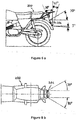
- This tool is specially sized to perform the control of the backplate of two-wheeled or three-wheeled vehicles, whose regulation in terms of placement (geometric visibility) and inclination is illustrated in Figures 6 and 7 according to Directive 2009/62 / EC.
- the 5A shows the range of maximum inclination allowed for a plate, upward (30 °) or downward (15 °). Also shown is the space to remain free near the plate, up (30 °) and down (5 °).
- the 5B represents the space to remain free near the plate, on either side of the median longitudinal plane of the vehicle, namely on the right (30 °) and on the left (30 °).
- the front frame 1 has dimensions in accordance with those recommended by the national standards in force for this type of vehicle.
- the tool is placed so that the outer face 15 of the front frame 1 bears against the license plate 201 of the vehicle 200.
- This is a plate mounted at the rear of the vehicle. a vehicle 200 with a two-wheeled motor.
- the front frame 1 therefore adopts the inclination of the plate.
- the operator will then adjust the orientation of the covers 2, 3, so as to bring the bubble level 6 horizontally. If this operation is possible without anything hindering the tool, the test is positive: the vehicle, or at least its license plate, is compliant.
- the covers 2, 3 to bring the level to the horizontal while keeping the front frame resting on the license plate or its support, the conclusion is that the installation of said plate does not comply with the regulations. The operator can easily diagnose the reason for this prevention to remedy it.
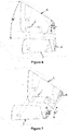
- the fig.6 and 7 illustrate two limit positions of a tool according to the invention, for values of inclination of a registration plate going from 15 ° to the bottom ( Fig. 6 ) at 30 ° upwards ( fig.7 ).
- the upper stops 7 form an angle of 30 ° with the front frame 1
- the lower tabs 8 form an angle of 15 ° with said front frame.
- the plate is inclined 15 ° downwards, the lower tabs 8 abut on the front frame.
- the upper stops 7 are in abutment on the front frame.
- the angle between the front frame and the cleats is in these two cases maximum, namely 45 °.
- the upper 2 and lower 3 covers remain in the orientation required for the geometric visibility, after adjustment until the horizontality by visual control of the spirit level carried by the support 6 '.
Landscapes
- Engineering & Computer Science (AREA)
- Mechanical Engineering (AREA)
- Physics & Mathematics (AREA)
- General Physics & Mathematics (AREA)
- Vehicle Waterproofing, Decoration, And Sanitation Devices (AREA)
Applications Claiming Priority (1)
| Application Number | Priority Date | Filing Date | Title |
|---|---|---|---|
| FR1502397A FR3043638B1 (fr) | 2015-11-17 | 2015-11-17 | Dispositif pour le placement d'une plaque d'immatriculation sur un vehicule |
Publications (1)
| Publication Number | Publication Date |
|---|---|
| EP3171122A1 true EP3171122A1 (de) | 2017-05-24 |
Family
ID=56084066
Family Applications (1)
| Application Number | Title | Priority Date | Filing Date |
|---|---|---|---|
| EP16199013.0A Withdrawn EP3171122A1 (de) | 2015-11-17 | 2016-11-16 | Vorrichtung zum überprüfen der position eines nummernschilds an einem fahrzeug und verwendung der vorrichtung |
Country Status (2)
| Country | Link |
|---|---|
| EP (1) | EP3171122A1 (de) |
| FR (1) | FR3043638B1 (de) |
Citations (4)
| Publication number | Priority date | Publication date | Assignee | Title |
|---|---|---|---|---|
| US4958451A (en) * | 1981-09-19 | 1990-09-25 | Honda Giken Kogyo Kabushiki Kaisha | Motorcycle license plate mounting mechanism |
| GB2429141A (en) * | 2005-08-06 | 2007-02-14 | Simulation Consultants Ltd | An ambient light shield |
| US20110277358A1 (en) * | 2010-05-12 | 2011-11-17 | Terence Richard Iceton | Anti-photo radar license plate attachment |
| US20140177925A1 (en) * | 2012-12-25 | 2014-06-26 | National Chiao Tung University | License plate recognition system and method |
-
2015
- 2015-11-17 FR FR1502397A patent/FR3043638B1/fr active Active
-
2016
- 2016-11-16 EP EP16199013.0A patent/EP3171122A1/de not_active Withdrawn
Patent Citations (4)
| Publication number | Priority date | Publication date | Assignee | Title |
|---|---|---|---|---|
| US4958451A (en) * | 1981-09-19 | 1990-09-25 | Honda Giken Kogyo Kabushiki Kaisha | Motorcycle license plate mounting mechanism |
| GB2429141A (en) * | 2005-08-06 | 2007-02-14 | Simulation Consultants Ltd | An ambient light shield |
| US20110277358A1 (en) * | 2010-05-12 | 2011-11-17 | Terence Richard Iceton | Anti-photo radar license plate attachment |
| US20140177925A1 (en) * | 2012-12-25 | 2014-06-26 | National Chiao Tung University | License plate recognition system and method |
Also Published As
| Publication number | Publication date |
|---|---|
| FR3043638A1 (fr) | 2017-05-19 |
| FR3043638B1 (fr) | 2018-05-25 |
Similar Documents
| Publication | Publication Date | Title |
|---|---|---|
| FR2712251A1 (fr) | Procédé et dispositif d'aide au pilotage d'un aéronef. | |
| FR3091329A1 (fr) | Système de feu de gabarit | |
| EP2394856A1 (de) | Verkleidungselement eines Kraftfahrzeugs, das eine Haltevorrichtung für ein tragbares Elektrogerät umfasst | |
| EP3171122A1 (de) | Vorrichtung zum überprüfen der position eines nummernschilds an einem fahrzeug und verwendung der vorrichtung | |
| EP3245117B1 (de) | Verfahren und vorrichtung zur unterstützung eines umkehrmanövers eines kraftfahrzeugs | |
| EP3512758B1 (de) | Verfahren zur fahrunterstützung, verfahren zur implementierung solch eines verfahrens und vorrichtung zur fahrunterstützung | |
| EP3871138A1 (de) | System und verfahren zur beleuchtung eines seitenbereichs eines fahrzeugs | |
| EP3177895B1 (de) | Anzeigevorrichtung, insbesondere ein druckmesser | |
| KR102281422B1 (ko) | 차량용 아웃사이드 영상 획득 장치 | |
| WO2016131104A1 (en) | Bicycle camera and bicycle camera system | |
| EP0021998B1 (de) | Apparat zum Feststellen des Durchmessers von Brillengläsern | |
| EP4058721B1 (de) | Beleuchtungsmodul für ein seitenteil eines fahrzeugs | |
| EP0028860A1 (de) | Aussenrückspiegel | |
| EP2650716B1 (de) | Zusammenklappbares stereoskopisches Anzeigegerät | |
| FR2988652A1 (fr) | Poste de conduite d'un vehicule automobile comprenant un ecran amovible | |
| FR3056803A1 (fr) | Dispositif d'aide a la conduite d'un vehicule par determination et affichage d'une distance d'adaptation de la vitesse dudit vehicule | |
| EP2762657A1 (de) | Einsatzschablone einer Motorantriebsanlage eines Öffnungsflügels, und Prüfverfahren mit Hilfe einer solchen Schablone | |
| WO1994028453A1 (fr) | Stereoscope pliable | |
| EP3137860B1 (de) | Verfahren zur hilfe bei der optischen bestimmung der masse eines fahrzeugs welches in einer zone mit wenig lichteinfall geparkt ist. | |
| FR3035042A1 (fr) | Ensemble comprenant un appareil electronique portatif et un support de fixation de l'appareil electronique portatif | |
| EP4444579B1 (de) | Funktionseinrichtung für ein kraftfahrzeug | |
| FR3056808A1 (fr) | Dispositif d'aide a la conduite d'un vehicule par determination et affichage de la distance d'adaptation de la vitesse dudit vehicule et d'un objet de la scene de route | |
| EP3437084B1 (de) | Verbesserte fussgängerorientierungsstruktur | |
| EP3461701A1 (de) | Vorrichtung zur verbindung eines wischerblatts mit einem scheibenwischerantriebsarm für fahrzeug | |
| FR3074115A1 (fr) | Dispositif de generation d’un environnement lumineux |
Legal Events
| Date | Code | Title | Description |
|---|---|---|---|
| PUAI | Public reference made under article 153(3) epc to a published international application that has entered the european phase |
Free format text: ORIGINAL CODE: 0009012 |
|
| AK | Designated contracting states |
Kind code of ref document: A1 Designated state(s): AL AT BE BG CH CY CZ DE DK EE ES FI FR GB GR HR HU IE IS IT LI LT LU LV MC MK MT NL NO PL PT RO RS SE SI SK SM TR |
|
| AX | Request for extension of the european patent |
Extension state: BA ME |
|
| STAA | Information on the status of an ep patent application or granted ep patent |
Free format text: STATUS: THE APPLICATION IS DEEMED TO BE WITHDRAWN |
|
| 18D | Application deemed to be withdrawn |
Effective date: 20171125 |