EP3171448A1 - Batteriemodul mit kühlstruktur mit minimierter biegung des kältemittelkanals - Google Patents
Batteriemodul mit kühlstruktur mit minimierter biegung des kältemittelkanals Download PDFInfo
- Publication number
- EP3171448A1 EP3171448A1 EP15842338.4A EP15842338A EP3171448A1 EP 3171448 A1 EP3171448 A1 EP 3171448A1 EP 15842338 A EP15842338 A EP 15842338A EP 3171448 A1 EP3171448 A1 EP 3171448A1
- Authority
- EP
- European Patent Office
- Prior art keywords
- battery module
- cooling
- battery
- frame member
- coolant
- Prior art date
- Legal status (The legal status is an assumption and is not a legal conclusion. Google has not performed a legal analysis and makes no representation as to the accuracy of the status listed.)
- Granted
Links
Images


Classifications
-
- H—ELECTRICITY
- H01—ELECTRIC ELEMENTS
- H01M—PROCESSES OR MEANS, e.g. BATTERIES, FOR THE DIRECT CONVERSION OF CHEMICAL ENERGY INTO ELECTRICAL ENERGY
- H01M10/00—Secondary cells; Manufacture thereof
- H01M10/04—Construction or manufacture in general
-
- B—PERFORMING OPERATIONS; TRANSPORTING
- B60—VEHICLES IN GENERAL
- B60L—PROPULSION OF ELECTRICALLY-PROPELLED VEHICLES; SUPPLYING ELECTRIC POWER FOR AUXILIARY EQUIPMENT OF ELECTRICALLY-PROPELLED VEHICLES; ELECTRODYNAMIC BRAKE SYSTEMS FOR VEHICLES IN GENERAL; MAGNETIC SUSPENSION OR LEVITATION FOR VEHICLES; MONITORING OPERATING VARIABLES OF ELECTRICALLY-PROPELLED VEHICLES; ELECTRIC SAFETY DEVICES FOR ELECTRICALLY-PROPELLED VEHICLES
- B60L3/00—Electric devices on electrically-propelled vehicles for safety purposes; Monitoring operating variables, e.g. speed, deceleration or energy consumption
- B60L3/0023—Detecting, eliminating, remedying or compensating for drive train abnormalities, e.g. failures within the drive train
- B60L3/0046—Detecting, eliminating, remedying or compensating for drive train abnormalities, e.g. failures within the drive train relating to electric energy storage systems, e.g. batteries or capacitors
-
- B—PERFORMING OPERATIONS; TRANSPORTING
- B60—VEHICLES IN GENERAL
- B60L—PROPULSION OF ELECTRICALLY-PROPELLED VEHICLES; SUPPLYING ELECTRIC POWER FOR AUXILIARY EQUIPMENT OF ELECTRICALLY-PROPELLED VEHICLES; ELECTRODYNAMIC BRAKE SYSTEMS FOR VEHICLES IN GENERAL; MAGNETIC SUSPENSION OR LEVITATION FOR VEHICLES; MONITORING OPERATING VARIABLES OF ELECTRICALLY-PROPELLED VEHICLES; ELECTRIC SAFETY DEVICES FOR ELECTRICALLY-PROPELLED VEHICLES
- B60L58/00—Methods or circuit arrangements for monitoring or controlling batteries or fuel cells, specially adapted for electric vehicles
- B60L58/10—Methods or circuit arrangements for monitoring or controlling batteries or fuel cells, specially adapted for electric vehicles for monitoring or controlling batteries
- B60L58/24—Methods or circuit arrangements for monitoring or controlling batteries or fuel cells, specially adapted for electric vehicles for monitoring or controlling batteries for controlling the temperature of batteries
- B60L58/26—Methods or circuit arrangements for monitoring or controlling batteries or fuel cells, specially adapted for electric vehicles for monitoring or controlling batteries for controlling the temperature of batteries by cooling
-
- H—ELECTRICITY
- H01—ELECTRIC ELEMENTS
- H01M—PROCESSES OR MEANS, e.g. BATTERIES, FOR THE DIRECT CONVERSION OF CHEMICAL ENERGY INTO ELECTRICAL ENERGY
- H01M10/00—Secondary cells; Manufacture thereof
- H01M10/60—Heating or cooling; Temperature control
- H01M10/61—Types of temperature control
- H01M10/613—Cooling or keeping cold
-
- H—ELECTRICITY
- H01—ELECTRIC ELEMENTS
- H01M—PROCESSES OR MEANS, e.g. BATTERIES, FOR THE DIRECT CONVERSION OF CHEMICAL ENERGY INTO ELECTRICAL ENERGY
- H01M10/00—Secondary cells; Manufacture thereof
- H01M10/60—Heating or cooling; Temperature control
- H01M10/62—Heating or cooling; Temperature control specially adapted for specific applications
- H01M10/623—Portable devices, e.g. mobile telephones, cameras or pacemakers
- H01M10/6235—Power tools
-
- H—ELECTRICITY
- H01—ELECTRIC ELEMENTS
- H01M—PROCESSES OR MEANS, e.g. BATTERIES, FOR THE DIRECT CONVERSION OF CHEMICAL ENERGY INTO ELECTRICAL ENERGY
- H01M10/00—Secondary cells; Manufacture thereof
- H01M10/60—Heating or cooling; Temperature control
- H01M10/62—Heating or cooling; Temperature control specially adapted for specific applications
- H01M10/625—Vehicles
-
- H—ELECTRICITY
- H01—ELECTRIC ELEMENTS
- H01M—PROCESSES OR MEANS, e.g. BATTERIES, FOR THE DIRECT CONVERSION OF CHEMICAL ENERGY INTO ELECTRICAL ENERGY
- H01M10/00—Secondary cells; Manufacture thereof
- H01M10/60—Heating or cooling; Temperature control
- H01M10/62—Heating or cooling; Temperature control specially adapted for specific applications
- H01M10/627—Stationary installations, e.g. power plant buffering or backup power supplies
-
- H—ELECTRICITY
- H01—ELECTRIC ELEMENTS
- H01M—PROCESSES OR MEANS, e.g. BATTERIES, FOR THE DIRECT CONVERSION OF CHEMICAL ENERGY INTO ELECTRICAL ENERGY
- H01M10/00—Secondary cells; Manufacture thereof
- H01M10/60—Heating or cooling; Temperature control
- H01M10/64—Heating or cooling; Temperature control characterised by the shape of the cells
- H01M10/647—Prismatic or flat cells, e.g. pouch cells
-
- H—ELECTRICITY
- H01—ELECTRIC ELEMENTS
- H01M—PROCESSES OR MEANS, e.g. BATTERIES, FOR THE DIRECT CONVERSION OF CHEMICAL ENERGY INTO ELECTRICAL ENERGY
- H01M10/00—Secondary cells; Manufacture thereof
- H01M10/60—Heating or cooling; Temperature control
- H01M10/65—Means for temperature control structurally associated with the cells
- H01M10/655—Solid structures for heat exchange or heat conduction
- H01M10/6551—Surfaces specially adapted for heat dissipation or radiation, e.g. fins or coatings
-
- H—ELECTRICITY
- H01—ELECTRIC ELEMENTS
- H01M—PROCESSES OR MEANS, e.g. BATTERIES, FOR THE DIRECT CONVERSION OF CHEMICAL ENERGY INTO ELECTRICAL ENERGY
- H01M10/00—Secondary cells; Manufacture thereof
- H01M10/60—Heating or cooling; Temperature control
- H01M10/65—Means for temperature control structurally associated with the cells
- H01M10/655—Solid structures for heat exchange or heat conduction
- H01M10/6554—Rods or plates
- H01M10/6555—Rods or plates arranged between the cells
-
- H—ELECTRICITY
- H01—ELECTRIC ELEMENTS
- H01M—PROCESSES OR MEANS, e.g. BATTERIES, FOR THE DIRECT CONVERSION OF CHEMICAL ENERGY INTO ELECTRICAL ENERGY
- H01M10/00—Secondary cells; Manufacture thereof
- H01M10/60—Heating or cooling; Temperature control
- H01M10/65—Means for temperature control structurally associated with the cells
- H01M10/655—Solid structures for heat exchange or heat conduction
- H01M10/6556—Solid parts with flow channel passages or pipes for heat exchange
- H01M10/6557—Solid parts with flow channel passages or pipes for heat exchange arranged between the cells
-
- H—ELECTRICITY
- H01—ELECTRIC ELEMENTS
- H01M—PROCESSES OR MEANS, e.g. BATTERIES, FOR THE DIRECT CONVERSION OF CHEMICAL ENERGY INTO ELECTRICAL ENERGY
- H01M10/00—Secondary cells; Manufacture thereof
- H01M10/60—Heating or cooling; Temperature control
- H01M10/65—Means for temperature control structurally associated with the cells
- H01M10/656—Means for temperature control structurally associated with the cells characterised by the type of heat-exchange fluid
- H01M10/6561—Gases
- H01M10/6566—Means within the gas flow to guide the flow around one or more cells, e.g. manifolds, baffles or other barriers
-
- H—ELECTRICITY
- H01—ELECTRIC ELEMENTS
- H01M—PROCESSES OR MEANS, e.g. BATTERIES, FOR THE DIRECT CONVERSION OF CHEMICAL ENERGY INTO ELECTRICAL ENERGY
- H01M50/00—Constructional details or processes of manufacture of the non-active parts of electrochemical cells other than fuel cells, e.g. hybrid cells
- H01M50/20—Mountings; Secondary casings or frames; Racks, modules or packs; Suspension devices; Shock absorbers; Transport or carrying devices; Holders
- H01M50/204—Racks, modules or packs for multiple batteries or multiple cells
- H01M50/207—Racks, modules or packs for multiple batteries or multiple cells characterised by their shape
- H01M50/211—Racks, modules or packs for multiple batteries or multiple cells characterised by their shape adapted for pouch cells
-
- H—ELECTRICITY
- H01—ELECTRIC ELEMENTS
- H01M—PROCESSES OR MEANS, e.g. BATTERIES, FOR THE DIRECT CONVERSION OF CHEMICAL ENERGY INTO ELECTRICAL ENERGY
- H01M50/00—Constructional details or processes of manufacture of the non-active parts of electrochemical cells other than fuel cells, e.g. hybrid cells
- H01M50/20—Mountings; Secondary casings or frames; Racks, modules or packs; Suspension devices; Shock absorbers; Transport or carrying devices; Holders
- H01M50/262—Mountings; Secondary casings or frames; Racks, modules or packs; Suspension devices; Shock absorbers; Transport or carrying devices; Holders with fastening means, e.g. locks
- H01M50/264—Mountings; Secondary casings or frames; Racks, modules or packs; Suspension devices; Shock absorbers; Transport or carrying devices; Holders with fastening means, e.g. locks for cells or batteries, e.g. straps, tie rods or peripheral frames
-
- B—PERFORMING OPERATIONS; TRANSPORTING
- B60—VEHICLES IN GENERAL
- B60L—PROPULSION OF ELECTRICALLY-PROPELLED VEHICLES; SUPPLYING ELECTRIC POWER FOR AUXILIARY EQUIPMENT OF ELECTRICALLY-PROPELLED VEHICLES; ELECTRODYNAMIC BRAKE SYSTEMS FOR VEHICLES IN GENERAL; MAGNETIC SUSPENSION OR LEVITATION FOR VEHICLES; MONITORING OPERATING VARIABLES OF ELECTRICALLY-PROPELLED VEHICLES; ELECTRIC SAFETY DEVICES FOR ELECTRICALLY-PROPELLED VEHICLES
- B60L2240/00—Control parameters of input or output; Target parameters
- B60L2240/40—Drive Train control parameters
- B60L2240/54—Drive Train control parameters related to batteries
- B60L2240/545—Temperature
-
- H—ELECTRICITY
- H01—ELECTRIC ELEMENTS
- H01M—PROCESSES OR MEANS, e.g. BATTERIES, FOR THE DIRECT CONVERSION OF CHEMICAL ENERGY INTO ELECTRICAL ENERGY
- H01M2220/00—Batteries for particular applications
- H01M2220/10—Batteries in stationary systems, e.g. emergency power source in plant
-
- H—ELECTRICITY
- H01—ELECTRIC ELEMENTS
- H01M—PROCESSES OR MEANS, e.g. BATTERIES, FOR THE DIRECT CONVERSION OF CHEMICAL ENERGY INTO ELECTRICAL ENERGY
- H01M2220/00—Batteries for particular applications
- H01M2220/20—Batteries in motive systems, e.g. vehicle, ship, plane
-
- H—ELECTRICITY
- H01—ELECTRIC ELEMENTS
- H01M—PROCESSES OR MEANS, e.g. BATTERIES, FOR THE DIRECT CONVERSION OF CHEMICAL ENERGY INTO ELECTRICAL ENERGY
- H01M2220/00—Batteries for particular applications
- H01M2220/30—Batteries in portable systems, e.g. mobile phone, laptop
-
- Y—GENERAL TAGGING OF NEW TECHNOLOGICAL DEVELOPMENTS; GENERAL TAGGING OF CROSS-SECTIONAL TECHNOLOGIES SPANNING OVER SEVERAL SECTIONS OF THE IPC; TECHNICAL SUBJECTS COVERED BY FORMER USPC CROSS-REFERENCE ART COLLECTIONS [XRACs] AND DIGESTS
- Y02—TECHNOLOGIES OR APPLICATIONS FOR MITIGATION OR ADAPTATION AGAINST CLIMATE CHANGE
- Y02E—REDUCTION OF GREENHOUSE GAS [GHG] EMISSIONS, RELATED TO ENERGY GENERATION, TRANSMISSION OR DISTRIBUTION
- Y02E60/00—Enabling technologies; Technologies with a potential or indirect contribution to GHG emissions mitigation
- Y02E60/10—Energy storage using batteries
-
- Y—GENERAL TAGGING OF NEW TECHNOLOGICAL DEVELOPMENTS; GENERAL TAGGING OF CROSS-SECTIONAL TECHNOLOGIES SPANNING OVER SEVERAL SECTIONS OF THE IPC; TECHNICAL SUBJECTS COVERED BY FORMER USPC CROSS-REFERENCE ART COLLECTIONS [XRACs] AND DIGESTS
- Y02—TECHNOLOGIES OR APPLICATIONS FOR MITIGATION OR ADAPTATION AGAINST CLIMATE CHANGE
- Y02P—CLIMATE CHANGE MITIGATION TECHNOLOGIES IN THE PRODUCTION OR PROCESSING OF GOODS
- Y02P70/00—Climate change mitigation technologies in the production process for final industrial or consumer products
- Y02P70/50—Manufacturing or production processes characterised by the final manufactured product
-
- Y—GENERAL TAGGING OF NEW TECHNOLOGICAL DEVELOPMENTS; GENERAL TAGGING OF CROSS-SECTIONAL TECHNOLOGIES SPANNING OVER SEVERAL SECTIONS OF THE IPC; TECHNICAL SUBJECTS COVERED BY FORMER USPC CROSS-REFERENCE ART COLLECTIONS [XRACs] AND DIGESTS
- Y02—TECHNOLOGIES OR APPLICATIONS FOR MITIGATION OR ADAPTATION AGAINST CLIMATE CHANGE
- Y02T—CLIMATE CHANGE MITIGATION TECHNOLOGIES RELATED TO TRANSPORTATION
- Y02T10/00—Road transport of goods or passengers
- Y02T10/60—Other road transportation technologies with climate change mitigation effect
- Y02T10/70—Energy storage systems for electromobility, e.g. batteries
-
- Y—GENERAL TAGGING OF NEW TECHNOLOGICAL DEVELOPMENTS; GENERAL TAGGING OF CROSS-SECTIONAL TECHNOLOGIES SPANNING OVER SEVERAL SECTIONS OF THE IPC; TECHNICAL SUBJECTS COVERED BY FORMER USPC CROSS-REFERENCE ART COLLECTIONS [XRACs] AND DIGESTS
- Y02—TECHNOLOGIES OR APPLICATIONS FOR MITIGATION OR ADAPTATION AGAINST CLIMATE CHANGE
- Y02T—CLIMATE CHANGE MITIGATION TECHNOLOGIES RELATED TO TRANSPORTATION
- Y02T90/00—Enabling technologies or technologies with a potential or indirect contribution to GHG emissions mitigation
- Y02T90/10—Technologies relating to charging of electric vehicles
- Y02T90/16—Information or communication technologies improving the operation of electric vehicles
Definitions
- the present invention relates to a battery module including a cooling structure in which a coolant channel is minimally bent.
- middle or large-sized devices such as vehicles, use a middle or large-sized battery module including a plurality of battery cells electrically connected to each other because high output and large capacity are necessary for the middle or large-sized devices.
- the middle or large-sized battery module is manufactured so as to have as small a size and weight as possible.
- a prismatic battery or a pouch-shaped battery which can be stacked with high integration and has a small weight to capacity ratio, is usually used as a battery cell of the middle or large-sized battery module.
- much interest is currently focused on the pouch-shaped battery, which uses an aluminum laminate sheet as a sheathing member, because the weight of the pouch-shaped battery is small, and it is easy to modify the shape of the pouch-shaped battery.
- Battery cells constituting the middle or large-sized battery module may be secondary batteries which can be charged and discharged. During charge and discharge of such a high-output, large-capacity secondary battery, a larger amount of heat is generated from the battery.
- the laminate sheet of each pouch-shaped battery widely used in the battery module has a polymer material exhibiting low thermal conductivity coated on the surface thereof with the result that it is difficult to effectively lower overall temperature of the battery cells.
- the middle or large-sized battery module or a middle or large-sized battery pack for vehicles which is a high-output, large-capacity battery, including a plurality of middle or large-sized battery modules needs a cooling system to cool battery cells mounted therein.
- Each battery module mounted in the middle or large-sized battery pack is generally manufactured by stacking a plurality of battery cells with high integration.
- the battery cells are stacked in a state in which the battery cells are arranged at predetermined intervals such that heat generated during charge and discharge of the battery cells can be removed.
- the battery cells may be sequentially stacked in a state in which the battery cells are arranged at predetermined intervals without using an additional member.
- one or more battery cells may be mounted in a frame member, such as a cartridge, to constitute a unit module, and a plurality of unit modules may be stacked to constitute a battery module.
- FIG. 1 is an exploded view schematically showing the structure of unit modules constituting a conventional battery module
- FIG. 2 is a typical view schematically showing the structure of the battery module of FIG. 1 when viewed from the front of the battery module.
- a battery module 100 is configured to have a structure in which a plurality of unit modules 110 is arranged in tight contact with one another.
- the battery module 100 is generally formed in a hexahedral shape.
- Each of the unit modules 110 is configured such that two plate-shaped battery cells 131 and 132 face each other while contacting each other in a state in which a frame member 12 is disposed between the battery cells 131 and 132.
- a cooling member 140 is interposed between the two plate-shaped battery cells 131 and 132, specifically between the frame member 120 and the battery cell 131 and/or between the frame member 120 and the battery cell 132.
- Cover members 151 and 152 are coupled to the front and the rear of the battery module 100, respectively.
- the cooling member 140 generally has a structure corresponding to the shape and the size of the plate-shaped battery cells 131 and 132.
- the cooling member 140 includes a plate-shaped cooling fin 141 having a shape and a size corresponding to those of the battery cells 131 and 132 and a coolant conduit 142 disposed along the outer edge of the cooling fin 141.
- the coolant conduit 142 has a hollow structure.
- the coolant conduit 142 includes a coolant inlet port 143 and a coolant outlet port 144 provided at a central region of the lower side of the cooling fin 141.
- the coolant inlet port 143 and the coolant outlet port 144 of the coolant conduit 142 are coupled respectively to cooling manifolds 161 and 162 located at the lower part of the battery module 100 in a communicating fashion.
- the battery module 100 is generally formed in a rectangular shape when viewed from the front of the battery module 100.
- the battery module 100 is provided at corners thereof with fastening parts 101, 102, 103, and 104 for coupling the unit modules.
- the cooling manifolds 161 and 162 are coupled to the lower part of the battery module 100. Specifically, the cooling manifolds 161 and 162 are coupled respectively to the coolant inlet port and the coolant outlet port of the coolant conduit 142 formed at the central region of the lower side of the cooling fin in a communicating fashion.
- the coolant inlet port 143 and the coolant outlet port 144 are located adjacent to an approximately central region of the lower part of the battery module 100.
- a coolant introduced through the cooling manifold 161 passes through the coolant inlet port 143 of the coolant conduit 142 and is then discharged through the cooling manifold 162 connected to the coolant outlet port 144, therefore, the coolant is circulated along the outer edge of the cooling fin 141, thereby maximizing cooling efficiency of the battery module 100.
- the coolant conduit 142 of the cooling member 140 which is provided along the outer edge of the cooling fin 141, is bent at six points 142a, 142b, 142c, 142d, 142e, and 142f.
- manufacturing cost of the cooling member 140 is increased.
- the pressure of the coolant along the outer edge of the cooling fin 141 through the coolant conduit 142 is lowered due to the bent structures with the result that the cooling efficiency of the battery module 100 may be lowered.
- the cooling manifolds 161 and 162 are coupled to the central region of the lower part of the battery module 100 at which the coolant inlet port 143 and the coolant outlet port 144 are located. At the time of manufacturing the battery module, therefore, it is necessary to individually couple the cooling manifolds 161 and 162 to the coolant inlet port 143 and the coolant outlet port 144 of the cooling member 140 of each of the unit modules 110 with the result that manufacturing time of the battery module 100 is increased. Furthermore, at the time of manufacturing a battery pack including two or more battery modules 100, the cooling manifolds 161 and 162 are located between each of the battery modules 100 and a tray assembly. As a result, it is not possible to directly inspect a coupling state between the cooling manifolds 161 and 162 and the coolant inlet port 143 and the coolant outlet port 144 with the naked eye, whereby a product defect rate is increased.
- the present invention has been made to solve the above problems and other technical problems that have yet to be resolved.
- a battery module is configured to have a structure in which a frame member is provided at opposite ends of one side thereof with cooling manifold elements in an integrated fashion, and a coolant channel defined by a coolant conduit connected to the cooling manifold elements is generally formed in a '[' shape, it is possible to minimize bending of the coolant conduit, thereby reducing manufacturing cost of the battery module, to prevent the reduction in pressure of a coolant, thereby improving cooling efficiency of the battery module, and to inspect coupling regions of the cooling manifold elements with the naked eye, thereby minimizing a product defect rate.
- the present invention has been completed based on these findings.
- a battery module configured to have a structure in which two or more unit modules, each of which includes one or more battery cells, a frame member configured to have a structure to surround outer edges of the one or more battery cells, the frame member including cooling manifold elements located at opposite ends of one side of the outer edges of the battery cells, and a cooling member mounted in the frame member such that the cooling member faces the battery cells while being in contact with the battery cells, the cooling member including a plate-shaped cooling fin having a shape and a size corresponding to those of the battery cells and a coolant conduit having a hollow structure located at an outer edge of the cooling fin, are arranged while being in tight contact with each other, wherein the coolant conduit includes a coolant inlet port and a coolant outlet port connected to the cooling manifold elements of the frame member of each of the unit modules in a communicating fashion.
- the battery module according to the present invention is configured to have a structure in which the frame member is provided at opposite ends of one side thereof with the cooling manifold elements in an integrated fashion, and a coolant channel defined by the coolant conduit connected to the cooling manifold elements is generally formed in a '[' shape, whereby it is possible to minimize bending of the coolant conduit, thereby reducing manufacturing cost of the battery module, to prevent the reduction in pressure of a coolant, thereby improving cooling efficiency of the battery module, and to inspect coupling regions of the cooling manifold elements with the naked eye, thereby minimizing a product defect rate.
- each of the battery cells is not particularly restricted so long as each of the battery cells is configured to have a structure in which the battery cells can face each other in a state in which the frame member, at which the cooling member is mounted, is disposed between the battery cells.
- each of the battery cells may be configured to have a structure in which an electrode assembly, which is configured to have a structure including a positive electrode, a negative electrode, and a separator disposed between the positive electrode and the negative electrode, is mounted in a receiving part of a pouch-shaped battery case made of a laminate sheet including a resin layer and a metal layer.
- the frame member has a hollow structure to surround the outer edges of the battery cells, and includes the plate-shaped cooling fin having the shape and the size corresponding to those of the battery cells. Consequently, the cooling fin is exposed to the outside. As a result, the exposed cooling fin directly faces the battery cells while being in contact with the battery cells, thereby improving cooling efficiency.
- cooling manifold elements may each have a structure extending through the frame member.
- the cooling manifold elements may each have a hollow structure extending from one surface to the other surface of the frame member.
- the frame member constituting each of the unit modules of the battery module according to the present invention is configured to have a plate-shaped structure based on the shape of each of the battery cells.
- the cooling manifold elements may be formed at opposite ends of one side of the outer edge of each of the battery cells, and the cooling manifold elements may each have a hollow structure extending from one surface to the other surface of the plate-shaped frame member.
- cooling manifold elements of the unit modules may be connected to each other in a communication fashion.
- each of the unit modules includes the frame member at which the cooling manifold elements are formed, and the cooling manifold elements are formed at the same regions of the unit modules such that each of the cooling manifold elements has a hollow structure.
- the cooling manifold elements of the unit modules may be connected to each other in a communication fashion.
- the battery module according to the present invention does not need additional cooling manifolds to supply and discharge a coolant through the coolant inlet port and the coolant outlet port formed at the coolant conduit of the cooling member, and it is possible to more easily configure the cooling manifold through connection of the cooling manifold elements based on arrangement of the unit modules.
- airtight gaskets may be disposed at connection regions of the cooling manifold elements.
- the frame member may be integrally formed with the cooling member, for example, by injection molding.
- the frame member may be manufactured by injection molding of a plastic resin or a polymer resin.
- the cooling member may be made of a metal, such as aluminum, exhibiting high thermal conductivity and may be integrally formed with the frame member in a state in which the cooling member is mounted in the frame member, during injection molding of the frame member.
- the frame member has a hollow structure to surround the outer edges of the battery cells.
- the coolant conduit of the cooling member and a portion of the cooling fin adjacent to the coolant conduit may be stably mounted and fixed to the frame member by injection molding.
- the remaining region of the cooling fin made of a metal, such as aluminum, is exposed to the outside such that the cooling fin directly faces the battery cells, thereby exhibiting an excellent cooling effect.
- the coolant conduit may be integrally formed with the cooling fin.
- the cooling conduit is located at the outer edge of the cooling fin.
- the cooling conduit and the cooling fin may be made of the same material.
- the coolant conduit may be configured to have a structure to surround the outer edge of the cooling fin excluding one side of the cooling fin corresponding to regions of the coolant conduit at which the coolant inlet port and the coolant outlet port are formed.
- the coolant conduit is located at the outer edge of the cooling fin, and the coolant inlet port and the coolant outlet port of the coolant conduit are connected to the respective cooling manifold elements of the frame member in a communicating fashion.
- the cooling manifold elements are located at opposite ends of one side of the outer edge of each of the battery cells.
- the coolant inlet port and the coolant outlet port of the coolant conduit connected to the respective cooling manifold elements based on the above structure are located at regions corresponding to the opposite ends of one side of the outer edge of each of the battery cells. Consequently, the coolant conduit may be configured to have a structure to surround the outer edge of the cooling fin excluding one side of the cooling fin corresponding to one side of each of the battery cells.
- the coolant conduit may be generally formed in a '[' shape, and the coolant channel defined by the coolant conduit may also be generally formed in a '[' shape.
- the coolant channel formed in the battery module according to the present invention may be minimally bent as compared with the coolant channel of the conventional battery module.
- the coolant inlet port and the coolant outlet port of the coolant conduit may be located such that ends of the coolant inlet port and the coolant outlet port are directed toward the bottom of the battery module.
- the bottom of the battery module may mean one surface of the battery module facing the top of the tray assembly in a case in which the battery module, which generally has a hexahedral shape, is arranged on the tray assembly to constitute a battery pack.
- the frame member may include upper end fastening extensions formed by extending in a protruding fashion opposite ends of the other side of the frame member opposite to one side of the frame member at which the cooling manifold elements are formed, and upper end fastening holes may be formed in the upper end fastening extensions, for example, by drilling.
- the frame member may include one or more lower end fastening extensions extending in a protruding fashion from regions of the frame member at which the cooling manifold elements are formed, and lower end fastening holes may be formed in the lower end fastening extensions, for example, by drilling.
- fastening beams for fixing the unit modules at correct positions may be inserted through the upper end fastening holes and the lower end fastening holes such that the unit modules are stably arranged in tight contact with each other and are fixed at correct positions, whereby it is possible to configure the battery module such that the battery module has a stable structure.
- the cooling fin of the cooling member may be provided at one side thereof at which the coolant inlet port and the coolant outlet port of the coolant conduit are located with one or more fixing and fastening extensions formed by extending portions of the cooling fin in a protruding fashion such that the fixing and fastening extensions are adjacent to the coolant inlet port and the coolant outlet port, and fixing and fastening holes may be formed in the fixing and fastening extensions, for example, by drilling.
- the cooling member may be fixed to the frame member by inserting fixing and fastening members through the fixing and fastening holes and the frame member.
- the frame member is integrally formed with the cooling member by injection molding as described above.
- the fixing and fastening holes of the fixing and fastening extensions formed at the cooling fin of the cooling member may function as a reference point for positioning the cooling member in a mold for injection molding of the frame member.
- the cooling member is fixed to the frame member by inserting the fixing and fastening members through the fixing and fastening holes of the fixing and fastening extensions formed at the cooling fin and the frame member. Consequently, it is possible to prevent release of the cooling member due to damage to the frame member, which has relatively low strength.
- a battery pack including the battery module with the above-stated construction, wherein the battery pack is configured to have a structure in which a battery module assembly, which is configured to have a structure in which two or more battery modules are arranged in tight contact with each other, is loaded on the top of a tray assembly.
- the battery module assembly may be configured to have a structure in which cooling manifold elements are arranged such that the cooling manifold elements are directed toward the top of the tray assembly.
- the cooling manifold elements are located at opposite ends of one side of each of the unit modules.
- the cooling manifold elements are located at opposite ends of the bottom of the battery module assembly facing the top of the tray assembly. Consequently, a tunnel-shaped space may be defined between the cooling manifold elements at a region between the top of the tray assembly and the bottom of the battery module assembly.
- the tray assembly may include a reinforcement bead provided at the top thereof facing the battery module assembly such that the reinforcement bead is located in the space defined between the cooling manifold elements of the battery module assembly.
- the cooling manifold elements may be formed at opposite ends of the bottom of the battery module assembly facing the tray assembly so as to form a predetermine space.
- the reinforcement bead may be disposed in the space, thereby improving rigidity of the tray assembly and thus improving structural stability of the battery pack.
- the reinforcement bead may have a height equivalent to 10% to 90%, specifically 50% to 70%, the distance between the battery module assembly and the top of the tray assembly in the space defined between the cooling manifold elements.
- the reinforcement bead has a width equivalent to 10% to 90%, specifically 50% to 70%, the width between the cooling manifold elements in the space defined between the cooling manifold elements.
- the reinforcement bead may damage the battery module assembly when the reinforcement bead is deformed due to external impact.
- the reinforcement bead may be integrally formed on the top of the tray assembly.
- the present invention is not limited thereto.
- the reinforcement bead may be formed on an additional member coupled to the top of the tray assembly.
- the reinforcement bead and the tray assembly may be made of the same material during molding of the tray assembly. Consequently, it is possible to reduce process time, thereby improving productivity.
- the reinforcement bead may be made of various materials based on desired rigidity.
- a reinforcement bead having an appropriate shape may be selectively applied and coupled to the tray assembly based on various shapes of the space defined between the cooling manifold elements at the bottom of the battery module assembly facing the top of the tray assembly. Consequently, an applicable range of the tray assembly may be increased.
- tray assemblies having different tops and reinforcement bead structures based on various shapes of the space defined between the cooling manifold elements whereby it is possible to reduce manufacturing cost of molds for manufacturing different tray assemblies.
- one or more fixing beams may be further coupled to one surface of the battery module assembly opposite to the other surface of the battery module assembly facing the top of the tray assembly.
- a device including one or more battery packs with the above-stated construction.
- the device may be any one selected from a group consisting of a power tool, an electric vehicle, a hybrid electric vehicle, a plug-in hybrid electric vehicle, and a power storage device.
- FIG. 3 is a typical view schematically showing the structure of a battery module according to an embodiment of the present invention.
- a battery module 300 is configured to have a structure in which two or more unit modules 310 are arranged in tight contact with each other.
- the battery module 300 is generally formed in a hexahedral shape.
- Cover members 321 and 322 are coupled respectively to the front and the rear of the battery module 300 such that the cover members 321 and 322 cover battery cells of the outermost unit modules 310 exposed to the outside. Consequently, it is possible to prevent the outermost battery cells from being damaged or contaminated due to external impact or contaminants, such as foreign matter.
- An integrated circuit board (ICB) 330 is mounted at the top of the battery module 300.
- the integrated circuit board 330 is covered by an integrated circuit board cover 331.
- a CVTN assembly 340 is mounted at the top of the integrated circuit board cover 331.
- Cooling manifold elements 351 and 352 of each of the unit modules 310 are connected to the lower part of the battery module 300 in a communicating fashion.
- the cooling manifold elements 351 and 352 extend along opposite ends of the lower part of the battery module 300 in straight lines.
- the cooling manifold elements 351 and 352 are exposed to the outside, and therefore it is possible to inspect coupling regions of the cooling manifold elements 351 and 352 with the naked eye, thereby minimizing a product defect rate.
- a tunnel-shaped space 360 is defined between the cooling manifold elements 351 and 352 at the lower part of the battery module 300.
- a reinforcement member may be provided in the space 360 defined between the bottom of the battery module assembly and the top of the tray assembly so as to increase rigidity of the battery pack, thereby improving structural stability of the battery pack.
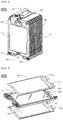
- FIG. 4 is an exploded view schematically showing the structure of a unit module constituting the battery module according to the embodiment of the present invention.
- a unit module 400 is configured to have a structure in which two battery cells 410 and 430 face each other in a state in which a frame member 420 and a cooling member mounted at the frame member 420 are disposed between the battery cells 410 and 430.
- Each of the battery cells 410 and 430 is configured to have a plate-shaped structure in which an electrode assembly, which is configured to have a structure including a positive electrode, a negative electrode, and a separator disposed between the positive electrode and the negative electrode, is mounted in a receiving part of a pouch-shaped battery case made of a laminate sheet including a resin layer and a metal layer.
- the battery cell 410 is provided at one side thereof with electrode terminals 411 and 412 in a protruding fashion.
- the battery cell 430 is provided at one side thereof with electrode terminals 431 and 432 in a protruding fashion.
- the electrode terminals 411, 412, 431, and 432 of the battery cells 410 and 430 protrude in the same direction.
- the frame member 420 is disposed between the battery cells 410 and 430.
- the frame member 420 is formed in a rectangular shape having a hollow structure to surround outer edges of the battery cells 410 and 430.
- the frame member 420 is integrally formed with the cooling member 440 by injection molding.
- the cooling member 440 is mounted in the frame member 420.
- a cooling fin 441 of the cooling member 440 is exposed through a hollow region of the frame member 420 such that the cooling fin 441 faces the battery cells 410 and 430 while contacting the battery cells 410 and 430.
- FIG. 5 is a typical view schematically showing the structure of the cooling member and the frame member constituting the unit module of FIG. 4 .
- the cooling member 440 includes a plate-shaped cooling fin 441 having a shape and a size corresponding to those of the battery cells and a coolant conduit 442 disposed along the outer edge of the cooling fin 441.
- the coolant conduit 442 has a hollow structure.
- the coolant conduit 442 includes a coolant inlet port and a coolant outlet port.
- the coolant inlet port 443 and the coolant outlet port 444 are located at opposite ends of the lower side of the cooling fin 441. Consequently, the coolant conduit 442 is configured to have a structure to surround the outer edge of the cooling fin 441 excluding the lower side of the cooling fin 441 at which the coolant inlet port 443 and the coolant outlet port 444 are located.
- the coolant conduit 442 is generally formed in a '[' shape. Consequently, the coolant conduit 442 is minimally bent as compared with the conventional battery module, thereby reducing manufacturing cost of the battery module.
- the cooling fin 441 is provided at the lower side thereof with fixing and fastening extensions 445 and 446, which are formed by extending portions of the cooling fin 441 in a protruding fashion.
- the fixing and fastening extensions 445 and 446 are located adjacent to the coolant inlet port 443 and the coolant outlet port 444.
- Fixing and fastening holes 445a and 446a are formed in the fixing and fastening extensions 445 and 446, respectively, by drilling.
- the cooling member 440 may be stably fixed to the frame member 420 by inserting fixing and fastening members through the fixing and fastening holes 445a and 446a and the frame member 420.
- the frame member 420 also has a shape and a size corresponding to those of the battery cells.
- the frame member 420 is configured to have a hollow structure, in which a middle region 420 is open, such that the frame member 320 surrounds the outer edges of the battery cells.
- the frame member 420 is provided at opposite ends of the lower side thereof with cooling manifold elements 423 and 424, respectively.
- the frame member 420 is provided at the upper side thereof with upper end fastening extensions 421 and 422, which are formed by extending opposite ends of the upper side of the frame member 420 in a protruding fashion.
- Upper end fastening holes 421a and 422a are formed in the upper end fastening extensions 421 and 422, respectively, by drilling.
- the frame member 420 is provided at the lower side thereof with lower end fastening extensions 425 and 426 extending in a protruding fashion from the regions of the frame member 420 at which the cooling manifold elements 423 and 424 are formed.
- Lower end fastening holes 425a and 426a are formed in the lower end fastening extensions 425 and 426, respectively, by drilling.
- Fastening beams for fixing the unit modules at correct positions are inserted through the upper end fastening holes 421a and 422a and the lower end fastening holes 425a and 426a.
- the unit modules are stably arranged while being in tight contact with each other, and are fixed at correct positions such that the battery module is configured to have a stable structure.
- the frame member 420 is integrally formed with the cooling member 440 by injection molding.
- a structure in which the cooling member 440 and the frame member 420 are integrated by injection molding is shown in a schematic typical view of FIG. 6 .
- the cooling member 440 is integrally formed with the frame member 420 by injection molding.
- the coolant conduit 442 of the cooling member 440 and a portion of the cooling fin 441 adjacent to the coolant conduit 442 is mounted in the frame member 420.
- the coolant inlet port 443 and the coolant outlet port 444 of the coolant conduit 442 are connected to the cooling manifold elements 423 and 424, respectively, in a communicating fashion.
- a coolant introduced through the cooling manifold element 423 passes through the coolant inlet port 443 and the coolant outlet port 444 and is then discharged through the cooling manifold element 424, therefore, the coolant is circulated along the cooling conduit 442.
- a coolant channel defined by the cooling conduit 442 has two bent regions 442a and 442b. As a result, the coolant channel is generally formed in a '[' shape.
- the coolant channel is minimally bent as compared with the conventional battery module, thereby preventing the reduction in pressure of the coolant and thus improving overall cooling efficiency of the battery module.
- FIG. 7 is a vertical sectional view schematically showing the structure of coupling regions between cooling manifold elements of unit modules in the battery module according to the embodiment of the present invention.
- cooling manifold elements 711 and 721 each are configured to have a hollow structure extending from one surface to the other surface of the frame member.
- the cooling manifold elements 711 and 712 communicate with coolant inlet ports 712 and 722, respectively.
- One ends 711 a and 721 a of the cooling manifold elements 711 and 721 have an outer diameter R1 corresponding to an inner diameter R2 of the other ends 711b and 721b of the cooling manifold elements 711 and 721.
- R1 an outer diameter corresponding to an inner diameter R2 of the other ends 711b and 721b of the cooling manifold elements 711 and 721.
- Grooves 724 having a predetermined depth are formed at the ends 711 a and 721 a of the cooling manifold elements 711 and 712 such that the grooves 724 extend along the outer surfaces of the ends 711 a and 721a of the cooling manifold elements 711 and 712.
- An airtight gasket 723, such as an O-ring, is disposed in each of the grooves 724.
- FIG. 8 is a typical view schematically showing the structure of a battery pack according to another embodiment of the present invention.
- a battery pack 800 is configured to have a structure in which a battery module assembly 810, which is configured to have a structure in which two or more battery modules 811 and 812 are arranged in tight contact with each other, is loaded on the top of a tray assembly 820.
- cooling manifold elements 813 and 814 are arranged such that the cooling manifold elements 813 and 814 are directed toward the top of the tray assembly 820.
- a reinforcement bead 821 is provided at the top of the tray assembly 820 facing the battery module assembly 810 such that the reinforcement bead 821 is located in a space defined between the cooling manifold elements 813 and 814 of the battery module assembly 810.
- the rigidity of the tray assembly 820 is improved as compared with a conventional battery pack including battery modules, whereby overall structural stability of the battery pack 800 is improved.
- two fixing beams 831 and 832 are further coupled to the top of the battery module assembly 810. As a result, movement of the battery module assembly 810 in the battery pack 800 is prevented, and the battery modules 811 and 812 constituting the battery module assembly 810 are fixed at correct positions.
- a battery module according to the present invention is configured to have a structure in which a frame member is provided at opposite ends of one side thereof with cooling manifold elements in an integrated fashion, and a coolant channel defined by a coolant conduit connected to the cooling manifold elements is generally formed in a '[' shape, whereby it is possible to minimize bending of the coolant conduit, thereby reducing manufacturing cost of the battery module.
Landscapes
- Engineering & Computer Science (AREA)
- Chemical & Material Sciences (AREA)
- Chemical Kinetics & Catalysis (AREA)
- Electrochemistry (AREA)
- General Chemical & Material Sciences (AREA)
- Manufacturing & Machinery (AREA)
- Power Engineering (AREA)
- Life Sciences & Earth Sciences (AREA)
- Sustainable Development (AREA)
- Sustainable Energy (AREA)
- Transportation (AREA)
- Mechanical Engineering (AREA)
- Biophysics (AREA)
- Battery Mounting, Suspending (AREA)
- Secondary Cells (AREA)
Priority Applications (1)
| Application Number | Priority Date | Filing Date | Title |
|---|---|---|---|
| PL15842338T PL3171448T3 (pl) | 2014-09-15 | 2015-08-24 | Moduł akumulatorowy zawierający strukturę chłodzącą mającą zminimalizowane zgięcie kanału dla czynnika chłodniczego |
Applications Claiming Priority (2)
| Application Number | Priority Date | Filing Date | Title |
|---|---|---|---|
| KR1020140121726A KR101840417B1 (ko) | 2014-09-15 | 2014-09-15 | 냉매 유로의 절곡이 최소화된 냉각 구조를 포함하는 전지모듈 |
| PCT/KR2015/008798 WO2016043441A1 (ko) | 2014-09-15 | 2015-08-24 | 냉매 유로의 절곡이 최소화된 냉각 구조를 포함하는 전지모듈 |
Publications (3)
| Publication Number | Publication Date |
|---|---|
| EP3171448A1 true EP3171448A1 (de) | 2017-05-24 |
| EP3171448A4 EP3171448A4 (de) | 2017-10-25 |
| EP3171448B1 EP3171448B1 (de) | 2018-10-10 |
Family
ID=55506783
Family Applications (1)
| Application Number | Title | Priority Date | Filing Date |
|---|---|---|---|
| EP15842338.4A Active EP3171448B1 (de) | 2014-09-15 | 2015-08-24 | Batteriemodul mit kühlstruktur mit minimierter biegung des kältemittelkanals |
Country Status (7)
| Country | Link |
|---|---|
| US (1) | US10333185B2 (de) |
| EP (1) | EP3171448B1 (de) |
| JP (1) | JP6445140B2 (de) |
| KR (1) | KR101840417B1 (de) |
| CN (2) | CN105428750B (de) |
| PL (1) | PL3171448T3 (de) |
| WO (1) | WO2016043441A1 (de) |
Cited By (2)
| Publication number | Priority date | Publication date | Assignee | Title |
|---|---|---|---|---|
| CN110178245A (zh) * | 2017-06-16 | 2019-08-27 | 株式会社Lg化学 | 电池模块、包括电池模块的电池组和包括电池组的车辆 |
| US12456777B2 (en) | 2019-11-21 | 2025-10-28 | Tesla, Inc. | Integrated energy storage system |
Families Citing this family (21)
| Publication number | Priority date | Publication date | Assignee | Title |
|---|---|---|---|---|
| KR101840417B1 (ko) | 2014-09-15 | 2018-03-20 | 주식회사 엘지화학 | 냉매 유로의 절곡이 최소화된 냉각 구조를 포함하는 전지모듈 |
| KR102562682B1 (ko) * | 2016-05-25 | 2023-08-03 | 삼성에스디아이 주식회사 | 배터리 모듈 |
| DE102016219283A1 (de) * | 2016-10-05 | 2018-04-05 | Bayerische Motoren Werke Aktiengesellschaft | Elektrischer Energiespeicher mit zwischen den Zellen angeordneten Kühlplatten zur Notkühlung |
| KR102117317B1 (ko) * | 2016-11-30 | 2020-06-01 | 주식회사 엘지화학 | 냉각 핀의 장착 방향이 교차 배열된 전지모듈 |
| US10468731B2 (en) * | 2017-01-20 | 2019-11-05 | Ford Global Technologies, Llc | Battery pack array frames with grounded thermal fins |
| JP2019061895A (ja) * | 2017-09-27 | 2019-04-18 | 本田技研工業株式会社 | ラミネート電池セル及びラミネート電池モジュール |
| CN110021777B (zh) * | 2018-01-08 | 2021-03-26 | 比亚迪股份有限公司 | 极芯、电池单元、电池模组及汽车 |
| WO2019134698A1 (zh) * | 2018-01-08 | 2019-07-11 | 比亚迪股份有限公司 | 电池单元、电池模组及汽车 |
| KR102077728B1 (ko) * | 2018-03-19 | 2020-04-07 | 주식회사 태화에스피 | 금속표면처리를 활용한 전지셀 어셈블리 케이스의 제조방법 |
| EP3553876B1 (de) * | 2018-04-09 | 2020-07-22 | Samsung SDI Co., Ltd. | Kältemittelverteiler |
| KR102603060B1 (ko) * | 2018-06-08 | 2023-11-16 | 현대자동차주식회사 | 차량용 배터리 냉각 장치 및 그 제조 방법 |
| KR102309630B1 (ko) * | 2018-09-10 | 2021-10-05 | 주식회사 엘지에너지솔루션 | Icb 조립체, 이를 포함한 배터리 모듈 및 그 제조 방법 |
| KR102424400B1 (ko) | 2018-09-13 | 2022-07-22 | 주식회사 엘지에너지솔루션 | 열수축성 튜브를 포함하는 배터리 모듈 |
| KR102358425B1 (ko) * | 2018-09-18 | 2022-02-03 | 주식회사 엘지에너지솔루션 | 전지 모듈 |
| KR20230004935A (ko) * | 2018-09-21 | 2023-01-06 | 미쯔이가가꾸가부시끼가이샤 | 금속/수지 복합 구조체, 금속/수지 복합 구조체의 제조 방법 및 냉각 장치 |
| JP7151493B2 (ja) * | 2019-01-15 | 2022-10-12 | トヨタ自動車株式会社 | 電池装置 |
| CN110518164B (zh) * | 2019-08-22 | 2024-09-24 | 宿州市艾尔新能源有限公司 | 一种具有散热结构的电池托盘 |
| DE102019218014A1 (de) * | 2019-11-22 | 2021-05-27 | Volkswagen Aktiengesellschaft | Batteriemodulträger |
| KR102885751B1 (ko) * | 2019-11-25 | 2025-11-14 | 주식회사 엘지에너지솔루션 | 방열핀을 구비한 전지셀 카트리지, 이를 포함하는 전지 모듈 및 이의 제조방법 |
| FR3105382B1 (fr) * | 2019-12-20 | 2023-08-04 | Valeo Systemes Thermiques | Dispositif de régulation thermique et procédé d’assemblage correspondant |
| KR20220129779A (ko) | 2021-03-17 | 2022-09-26 | 주식회사 엘지에너지솔루션 | 배터리 팩 어셈블리 및 그 제조방법 |
Family Cites Families (17)
| Publication number | Priority date | Publication date | Assignee | Title |
|---|---|---|---|---|
| US8758924B2 (en) | 2007-06-18 | 2014-06-24 | Tesla Motors, Inc. | Extruded and ribbed thermal interface for use with a battery cooling system |
| KR101029838B1 (ko) | 2007-06-28 | 2011-04-15 | 주식회사 엘지화학 | 냉각 효율이 향상된 중대형 전지팩 |
| US8465863B2 (en) | 2008-04-09 | 2013-06-18 | GM Global Technology Operations LLC | Batteries and components thereof and methods of making and assembling the same |
| US8110300B2 (en) * | 2008-06-30 | 2012-02-07 | Lg Chem, Ltd. | Battery mounting system |
| US8426050B2 (en) | 2008-06-30 | 2013-04-23 | Lg Chem, Ltd. | Battery module having cooling manifold and method for cooling battery module |
| KR101130043B1 (ko) | 2009-07-27 | 2012-03-28 | 주식회사 엘지화학 | 냉각 효율성이 향상된 전지모듈 |
| US8877366B2 (en) * | 2010-01-04 | 2014-11-04 | GM Global Technology Operations LLC | Cooling plate for lithium-ion battery pack |
| KR101205180B1 (ko) * | 2010-05-18 | 2012-11-27 | 주식회사 엘지화학 | 콤팩트하고 안정성이 우수한 냉각부재와 이를 포함하는 전지모듈 |
| EP2390951A1 (de) * | 2010-05-26 | 2011-11-30 | MANN+HUMMEL GmbH | Wärmeübertragungsmodul für Batteriezellen und Batterieanordnung damit |
| US9065158B2 (en) * | 2010-05-28 | 2015-06-23 | GM Global Technology Operations LLC | Corrugated fin and frame assembly for battery cooling |
| US8673473B2 (en) | 2010-08-10 | 2014-03-18 | GM Global Technology Operations LLC | Integrated cooling fin and frame |
| EP2601705B1 (de) | 2010-09-02 | 2015-10-07 | Akasol GmbH | Batteriezellen-kühlmodul und verfahren zum herstellen eines batteriezellen-kühlmoduls |
| KR20120053593A (ko) * | 2010-11-18 | 2012-05-29 | 주식회사 엘지화학 | 우수한 냉각 효율성의 전지팩 |
| KR20130008142A (ko) * | 2011-07-12 | 2013-01-22 | 에스케이이노베이션 주식회사 | 2차 전지 배터리 팩 |
| KR101750066B1 (ko) | 2011-12-02 | 2017-06-23 | 에스케이이노베이션 주식회사 | 수냉식 이차전지 |
| KR101781923B1 (ko) | 2013-02-05 | 2017-09-26 | 한온시스템 주식회사 | 배터리 냉각장치 |
| KR101840417B1 (ko) | 2014-09-15 | 2018-03-20 | 주식회사 엘지화학 | 냉매 유로의 절곡이 최소화된 냉각 구조를 포함하는 전지모듈 |
-
2014
- 2014-09-15 KR KR1020140121726A patent/KR101840417B1/ko active Active
-
2015
- 2015-08-24 US US15/504,405 patent/US10333185B2/en active Active
- 2015-08-24 EP EP15842338.4A patent/EP3171448B1/de active Active
- 2015-08-24 JP JP2017508659A patent/JP6445140B2/ja active Active
- 2015-08-24 WO PCT/KR2015/008798 patent/WO2016043441A1/ko not_active Ceased
- 2015-08-24 PL PL15842338T patent/PL3171448T3/pl unknown
- 2015-09-15 CN CN201510587694.8A patent/CN105428750B/zh active Active
- 2015-09-15 CN CN201520715205.8U patent/CN205141096U/zh not_active Expired - Lifetime
Cited By (5)
| Publication number | Priority date | Publication date | Assignee | Title |
|---|---|---|---|---|
| CN110178245A (zh) * | 2017-06-16 | 2019-08-27 | 株式会社Lg化学 | 电池模块、包括电池模块的电池组和包括电池组的车辆 |
| EP3561902A4 (de) * | 2017-06-16 | 2020-06-17 | LG Chem, Ltd. | Batteriemodul, batteriepack mit dem batteriemodul und fahrzeug mit dem batteriepack |
| US11158895B2 (en) | 2017-06-16 | 2021-10-26 | Lg Chem, Ltd. | Battery module, battery pack including battery module, and vehicle including battery pack |
| CN110178245B (zh) * | 2017-06-16 | 2022-05-27 | 株式会社Lg新能源 | 电池模块、包括电池模块的电池组和包括电池组的车辆 |
| US12456777B2 (en) | 2019-11-21 | 2025-10-28 | Tesla, Inc. | Integrated energy storage system |
Also Published As
| Publication number | Publication date |
|---|---|
| JP2017532720A (ja) | 2017-11-02 |
| CN105428750B (zh) | 2018-09-21 |
| WO2016043441A1 (ko) | 2016-03-24 |
| EP3171448A4 (de) | 2017-10-25 |
| US10333185B2 (en) | 2019-06-25 |
| JP6445140B2 (ja) | 2018-12-26 |
| PL3171448T3 (pl) | 2019-09-30 |
| US20170237130A1 (en) | 2017-08-17 |
| CN105428750A (zh) | 2016-03-23 |
| KR101840417B1 (ko) | 2018-03-20 |
| CN205141096U (zh) | 2016-04-06 |
| EP3171448B1 (de) | 2018-10-10 |
| KR20160031718A (ko) | 2016-03-23 |
Similar Documents
| Publication | Publication Date | Title |
|---|---|---|
| EP3171448B1 (de) | Batteriemodul mit kühlstruktur mit minimierter biegung des kältemittelkanals | |
| KR101658594B1 (ko) | 이차 전지용 프레임 및 이를 포함하는 배터리 모듈 | |
| KR101803958B1 (ko) | 효율적인 냉각 구조의 전지팩 케이스 | |
| US9184477B2 (en) | Battery pack of excellent cooling efficiency | |
| CN102484297B (zh) | 具有冷却结构的电池组 | |
| US9786968B2 (en) | Battery module assembly having coolant flow channel | |
| US9312579B2 (en) | Battery pack of excellent cooling efficiency | |
| KR101609232B1 (ko) | 냉매 유로가 형성된 카트리지를 포함하는 전지모듈 | |
| US20140234691A1 (en) | Battery module with novel structure | |
| KR20140011439A (ko) | 간접 공냉 구조를 포함하는 전지모듈 | |
| KR20170062845A (ko) | 구성이 간소화된 단위모듈을 포함하고 있는 전지모듈 | |
| US20070124980A1 (en) | Cartridge for middle or large-sized battery pack | |
| KR101623251B1 (ko) | 이차 전지모듈의 냉각시스템 | |
| KR101535795B1 (ko) | 공냉식 구조의 전지팩 | |
| US20250141003A1 (en) | Battery module and method for manufacturing the same | |
| KR102842878B1 (ko) | 냉각부 일체형 배터리 케이스 및 이의 제조방법 | |
| US20260066386A1 (en) | Battery Apparatus and Method for Cooling Battery Apparatus | |
| CN118891773A (zh) | 电池模块及其制造方法 | |
| KR20230165112A (ko) | 전지 모듈 및 전지 모듈의 제조 방법 | |
| KR20140130086A (ko) | 공냉식 구조의 전지팩 |
Legal Events
| Date | Code | Title | Description |
|---|---|---|---|
| STAA | Information on the status of an ep patent application or granted ep patent |
Free format text: STATUS: THE INTERNATIONAL PUBLICATION HAS BEEN MADE |
|
| PUAI | Public reference made under article 153(3) epc to a published international application that has entered the european phase |
Free format text: ORIGINAL CODE: 0009012 |
|
| STAA | Information on the status of an ep patent application or granted ep patent |
Free format text: STATUS: REQUEST FOR EXAMINATION WAS MADE |
|
| 17P | Request for examination filed |
Effective date: 20170215 |
|
| AK | Designated contracting states |
Kind code of ref document: A1 Designated state(s): AL AT BE BG CH CY CZ DE DK EE ES FI FR GB GR HR HU IE IS IT LI LT LU LV MC MK MT NL NO PL PT RO RS SE SI SK SM TR |
|
| AX | Request for extension of the european patent |
Extension state: BA ME |
|
| RIC1 | Information provided on ipc code assigned before grant |
Ipc: H01M 2/10 20060101AFI20170629BHEP Ipc: H01M 10/613 20140101ALI20170629BHEP Ipc: H01M 10/6557 20140101ALI20170629BHEP Ipc: H01M 10/647 20140101ALI20170629BHEP Ipc: H01M 10/6555 20140101ALI20170629BHEP Ipc: B60L 11/18 20060101ALI20170629BHEP Ipc: H01M 10/625 20140101ALI20170629BHEP |
|
| A4 | Supplementary search report drawn up and despatched |
Effective date: 20170921 |
|
| RIC1 | Information provided on ipc code assigned before grant |
Ipc: H01M 10/6557 20140101ALI20170915BHEP Ipc: H01M 10/6555 20140101ALI20170915BHEP Ipc: H01M 10/613 20140101ALI20170915BHEP Ipc: H01M 10/625 20140101ALI20170915BHEP Ipc: H01M 2/10 20060101AFI20170915BHEP Ipc: H01M 10/647 20140101ALI20170915BHEP Ipc: B60L 11/18 20060101ALI20170915BHEP |
|
| DAV | Request for validation of the european patent (deleted) | ||
| DAX | Request for extension of the european patent (deleted) | ||
| RIN1 | Information on inventor provided before grant (corrected) |
Inventor name: ROH, TAE HWAN Inventor name: KIM, NAM IN Inventor name: KIM, TAE HYUCK Inventor name: LEE, YOONHEE Inventor name: JUNG, JUNHEE |
|
| REG | Reference to a national code |
Ref country code: DE Ref legal event code: R079 Ref document number: 602015018093 Country of ref document: DE Free format text: PREVIOUS MAIN CLASS: H01M0010650000 Ipc: H01M0002100000 |
|
| GRAP | Despatch of communication of intention to grant a patent |
Free format text: ORIGINAL CODE: EPIDOSNIGR1 |
|
| STAA | Information on the status of an ep patent application or granted ep patent |
Free format text: STATUS: GRANT OF PATENT IS INTENDED |
|
| RIC1 | Information provided on ipc code assigned before grant |
Ipc: B60L 11/18 20060101ALI20180716BHEP Ipc: H01M 10/613 20140101ALI20180716BHEP Ipc: H01M 10/6556 20140101ALI20180716BHEP Ipc: H01M 2/10 20060101AFI20180716BHEP Ipc: H01M 10/6557 20140101ALI20180716BHEP Ipc: B60L 3/00 20060101ALI20180716BHEP Ipc: H01M 10/647 20140101ALI20180716BHEP Ipc: H01M 10/625 20140101ALI20180716BHEP Ipc: H01M 10/6555 20140101ALI20180716BHEP Ipc: H01M 10/6554 20140101ALI20180716BHEP |
|
| INTG | Intention to grant announced |
Effective date: 20180802 |
|
| RIN1 | Information on inventor provided before grant (corrected) |
Inventor name: KIM, TAE HYUCK Inventor name: KIM, NAM IN Inventor name: ROH, TAE HWAN Inventor name: LEE, YOONHEE Inventor name: JUNG, JUNHEE |
|
| GRAS | Grant fee paid |
Free format text: ORIGINAL CODE: EPIDOSNIGR3 |
|
| GRAA | (expected) grant |
Free format text: ORIGINAL CODE: 0009210 |
|
| STAA | Information on the status of an ep patent application or granted ep patent |
Free format text: STATUS: THE PATENT HAS BEEN GRANTED |
|
| AK | Designated contracting states |
Kind code of ref document: B1 Designated state(s): AL AT BE BG CH CY CZ DE DK EE ES FI FR GB GR HR HU IE IS IT LI LT LU LV MC MK MT NL NO PL PT RO RS SE SI SK SM TR |
|
| REG | Reference to a national code |
Ref country code: GB Ref legal event code: FG4D |
|
| REG | Reference to a national code |
Ref country code: CH Ref legal event code: EP Ref country code: AT Ref legal event code: REF Ref document number: 1052276 Country of ref document: AT Kind code of ref document: T Effective date: 20181015 |
|
| REG | Reference to a national code |
Ref country code: IE Ref legal event code: FG4D |
|
| REG | Reference to a national code |
Ref country code: DE Ref legal event code: R096 Ref document number: 602015018093 Country of ref document: DE |
|
| REG | Reference to a national code |
Ref country code: NL Ref legal event code: MP Effective date: 20181010 |
|
| REG | Reference to a national code |
Ref country code: LT Ref legal event code: MG4D |
|
| REG | Reference to a national code |
Ref country code: AT Ref legal event code: MK05 Ref document number: 1052276 Country of ref document: AT Kind code of ref document: T Effective date: 20181010 |
|
| PG25 | Lapsed in a contracting state [announced via postgrant information from national office to epo] |
Ref country code: NL Free format text: LAPSE BECAUSE OF FAILURE TO SUBMIT A TRANSLATION OF THE DESCRIPTION OR TO PAY THE FEE WITHIN THE PRESCRIBED TIME-LIMIT Effective date: 20181010 |
|
| PG25 | Lapsed in a contracting state [announced via postgrant information from national office to epo] |
Ref country code: FI Free format text: LAPSE BECAUSE OF FAILURE TO SUBMIT A TRANSLATION OF THE DESCRIPTION OR TO PAY THE FEE WITHIN THE PRESCRIBED TIME-LIMIT Effective date: 20181010 Ref country code: BG Free format text: LAPSE BECAUSE OF FAILURE TO SUBMIT A TRANSLATION OF THE DESCRIPTION OR TO PAY THE FEE WITHIN THE PRESCRIBED TIME-LIMIT Effective date: 20190110 Ref country code: HR Free format text: LAPSE BECAUSE OF FAILURE TO SUBMIT A TRANSLATION OF THE DESCRIPTION OR TO PAY THE FEE WITHIN THE PRESCRIBED TIME-LIMIT Effective date: 20181010 Ref country code: LV Free format text: LAPSE BECAUSE OF FAILURE TO SUBMIT A TRANSLATION OF THE DESCRIPTION OR TO PAY THE FEE WITHIN THE PRESCRIBED TIME-LIMIT Effective date: 20181010 Ref country code: AT Free format text: LAPSE BECAUSE OF FAILURE TO SUBMIT A TRANSLATION OF THE DESCRIPTION OR TO PAY THE FEE WITHIN THE PRESCRIBED TIME-LIMIT Effective date: 20181010 Ref country code: ES Free format text: LAPSE BECAUSE OF FAILURE TO SUBMIT A TRANSLATION OF THE DESCRIPTION OR TO PAY THE FEE WITHIN THE PRESCRIBED TIME-LIMIT Effective date: 20181010 Ref country code: NO Free format text: LAPSE BECAUSE OF FAILURE TO SUBMIT A TRANSLATION OF THE DESCRIPTION OR TO PAY THE FEE WITHIN THE PRESCRIBED TIME-LIMIT Effective date: 20190110 Ref country code: LT Free format text: LAPSE BECAUSE OF FAILURE TO SUBMIT A TRANSLATION OF THE DESCRIPTION OR TO PAY THE FEE WITHIN THE PRESCRIBED TIME-LIMIT Effective date: 20181010 Ref country code: IS Free format text: LAPSE BECAUSE OF FAILURE TO SUBMIT A TRANSLATION OF THE DESCRIPTION OR TO PAY THE FEE WITHIN THE PRESCRIBED TIME-LIMIT Effective date: 20190210 |
|
| PG25 | Lapsed in a contracting state [announced via postgrant information from national office to epo] |
Ref country code: PT Free format text: LAPSE BECAUSE OF FAILURE TO SUBMIT A TRANSLATION OF THE DESCRIPTION OR TO PAY THE FEE WITHIN THE PRESCRIBED TIME-LIMIT Effective date: 20190210 Ref country code: GR Free format text: LAPSE BECAUSE OF FAILURE TO SUBMIT A TRANSLATION OF THE DESCRIPTION OR TO PAY THE FEE WITHIN THE PRESCRIBED TIME-LIMIT Effective date: 20190111 Ref country code: RS Free format text: LAPSE BECAUSE OF FAILURE TO SUBMIT A TRANSLATION OF THE DESCRIPTION OR TO PAY THE FEE WITHIN THE PRESCRIBED TIME-LIMIT Effective date: 20181010 Ref country code: AL Free format text: LAPSE BECAUSE OF FAILURE TO SUBMIT A TRANSLATION OF THE DESCRIPTION OR TO PAY THE FEE WITHIN THE PRESCRIBED TIME-LIMIT Effective date: 20181010 Ref country code: SE Free format text: LAPSE BECAUSE OF FAILURE TO SUBMIT A TRANSLATION OF THE DESCRIPTION OR TO PAY THE FEE WITHIN THE PRESCRIBED TIME-LIMIT Effective date: 20181010 |
|
| REG | Reference to a national code |
Ref country code: DE Ref legal event code: R097 Ref document number: 602015018093 Country of ref document: DE |
|
| PG25 | Lapsed in a contracting state [announced via postgrant information from national office to epo] |
Ref country code: IT Free format text: LAPSE BECAUSE OF FAILURE TO SUBMIT A TRANSLATION OF THE DESCRIPTION OR TO PAY THE FEE WITHIN THE PRESCRIBED TIME-LIMIT Effective date: 20181010 Ref country code: CZ Free format text: LAPSE BECAUSE OF FAILURE TO SUBMIT A TRANSLATION OF THE DESCRIPTION OR TO PAY THE FEE WITHIN THE PRESCRIBED TIME-LIMIT Effective date: 20181010 Ref country code: DK Free format text: LAPSE BECAUSE OF FAILURE TO SUBMIT A TRANSLATION OF THE DESCRIPTION OR TO PAY THE FEE WITHIN THE PRESCRIBED TIME-LIMIT Effective date: 20181010 |
|
| PLBE | No opposition filed within time limit |
Free format text: ORIGINAL CODE: 0009261 |
|
| STAA | Information on the status of an ep patent application or granted ep patent |
Free format text: STATUS: NO OPPOSITION FILED WITHIN TIME LIMIT |
|
| PG25 | Lapsed in a contracting state [announced via postgrant information from national office to epo] |
Ref country code: EE Free format text: LAPSE BECAUSE OF FAILURE TO SUBMIT A TRANSLATION OF THE DESCRIPTION OR TO PAY THE FEE WITHIN THE PRESCRIBED TIME-LIMIT Effective date: 20181010 Ref country code: SM Free format text: LAPSE BECAUSE OF FAILURE TO SUBMIT A TRANSLATION OF THE DESCRIPTION OR TO PAY THE FEE WITHIN THE PRESCRIBED TIME-LIMIT Effective date: 20181010 Ref country code: SK Free format text: LAPSE BECAUSE OF FAILURE TO SUBMIT A TRANSLATION OF THE DESCRIPTION OR TO PAY THE FEE WITHIN THE PRESCRIBED TIME-LIMIT Effective date: 20181010 Ref country code: RO Free format text: LAPSE BECAUSE OF FAILURE TO SUBMIT A TRANSLATION OF THE DESCRIPTION OR TO PAY THE FEE WITHIN THE PRESCRIBED TIME-LIMIT Effective date: 20181010 |
|
| 26N | No opposition filed |
Effective date: 20190711 |
|
| PG25 | Lapsed in a contracting state [announced via postgrant information from national office to epo] |
Ref country code: SI Free format text: LAPSE BECAUSE OF FAILURE TO SUBMIT A TRANSLATION OF THE DESCRIPTION OR TO PAY THE FEE WITHIN THE PRESCRIBED TIME-LIMIT Effective date: 20181010 |
|
| PG25 | Lapsed in a contracting state [announced via postgrant information from national office to epo] |
Ref country code: TR Free format text: LAPSE BECAUSE OF FAILURE TO SUBMIT A TRANSLATION OF THE DESCRIPTION OR TO PAY THE FEE WITHIN THE PRESCRIBED TIME-LIMIT Effective date: 20181010 |
|
| PG25 | Lapsed in a contracting state [announced via postgrant information from national office to epo] |
Ref country code: LU Free format text: LAPSE BECAUSE OF NON-PAYMENT OF DUE FEES Effective date: 20190824 Ref country code: LI Free format text: LAPSE BECAUSE OF NON-PAYMENT OF DUE FEES Effective date: 20190831 Ref country code: MC Free format text: LAPSE BECAUSE OF FAILURE TO SUBMIT A TRANSLATION OF THE DESCRIPTION OR TO PAY THE FEE WITHIN THE PRESCRIBED TIME-LIMIT Effective date: 20181010 Ref country code: CH Free format text: LAPSE BECAUSE OF NON-PAYMENT OF DUE FEES Effective date: 20190831 |
|
| REG | Reference to a national code |
Ref country code: BE Ref legal event code: MM Effective date: 20190831 |
|
| PG25 | Lapsed in a contracting state [announced via postgrant information from national office to epo] |
Ref country code: IE Free format text: LAPSE BECAUSE OF NON-PAYMENT OF DUE FEES Effective date: 20190824 |
|
| PG25 | Lapsed in a contracting state [announced via postgrant information from national office to epo] |
Ref country code: BE Free format text: LAPSE BECAUSE OF NON-PAYMENT OF DUE FEES Effective date: 20190831 |
|
| REG | Reference to a national code |
Ref country code: DE Ref legal event code: R079 Ref document number: 602015018093 Country of ref document: DE Free format text: PREVIOUS MAIN CLASS: H01M0002100000 Ipc: H01M0050200000 |
|
| PG25 | Lapsed in a contracting state [announced via postgrant information from national office to epo] |
Ref country code: CY Free format text: LAPSE BECAUSE OF FAILURE TO SUBMIT A TRANSLATION OF THE DESCRIPTION OR TO PAY THE FEE WITHIN THE PRESCRIBED TIME-LIMIT Effective date: 20181010 |
|
| PG25 | Lapsed in a contracting state [announced via postgrant information from national office to epo] |
Ref country code: MT Free format text: LAPSE BECAUSE OF FAILURE TO SUBMIT A TRANSLATION OF THE DESCRIPTION OR TO PAY THE FEE WITHIN THE PRESCRIBED TIME-LIMIT Effective date: 20181010 Ref country code: HU Free format text: LAPSE BECAUSE OF FAILURE TO SUBMIT A TRANSLATION OF THE DESCRIPTION OR TO PAY THE FEE WITHIN THE PRESCRIBED TIME-LIMIT; INVALID AB INITIO Effective date: 20150824 |
|
| PG25 | Lapsed in a contracting state [announced via postgrant information from national office to epo] |
Ref country code: MK Free format text: LAPSE BECAUSE OF FAILURE TO SUBMIT A TRANSLATION OF THE DESCRIPTION OR TO PAY THE FEE WITHIN THE PRESCRIBED TIME-LIMIT Effective date: 20181010 |
|
| P01 | Opt-out of the competence of the unified patent court (upc) registered |
Effective date: 20230512 |
|
| REG | Reference to a national code |
Ref country code: DE Ref legal event code: R081 Ref document number: 602015018093 Country of ref document: DE Owner name: LG ENERGY SOLUTION, LTD., KR Free format text: FORMER OWNER: LG CHEM LTD., SEOUL, KR |
|
| REG | Reference to a national code |
Ref country code: GB Ref legal event code: 732E Free format text: REGISTERED BETWEEN 20230824 AND 20230831 |
|
| PGFP | Annual fee paid to national office [announced via postgrant information from national office to epo] |
Ref country code: DE Payment date: 20250721 Year of fee payment: 11 |
|
| PGFP | Annual fee paid to national office [announced via postgrant information from national office to epo] |
Ref country code: PL Payment date: 20250723 Year of fee payment: 11 |
|
| PGFP | Annual fee paid to national office [announced via postgrant information from national office to epo] |
Ref country code: GB Payment date: 20250722 Year of fee payment: 11 |
|
| PGFP | Annual fee paid to national office [announced via postgrant information from national office to epo] |
Ref country code: FR Payment date: 20250725 Year of fee payment: 11 |