EP3171471B1 - Adaptateur pour chemin de câbles, et système de répartition de câbles - Google Patents
Adaptateur pour chemin de câbles, et système de répartition de câbles Download PDFInfo
- Publication number
- EP3171471B1 EP3171471B1 EP14897519.6A EP14897519A EP3171471B1 EP 3171471 B1 EP3171471 B1 EP 3171471B1 EP 14897519 A EP14897519 A EP 14897519A EP 3171471 B1 EP3171471 B1 EP 3171471B1
- Authority
- EP
- European Patent Office
- Prior art keywords
- adapter
- connection part
- sidewall
- cable
- cable raceway
- Prior art date
- Legal status (The legal status is an assumption and is not a legal conclusion. Google has not performed a legal analysis and makes no representation as to the accuracy of the status listed.)
- Active
Links
Images






Classifications
-
- H—ELECTRICITY
- H02—GENERATION; CONVERSION OR DISTRIBUTION OF ELECTRIC POWER
- H02G—INSTALLATION OF ELECTRIC CABLES OR LINES, OR OF COMBINED OPTICAL AND ELECTRIC CABLES OR LINES
- H02G3/00—Installations of electric cables or lines or protective tubing therefor in or on buildings, equivalent structures or vehicles
- H02G3/02—Details
- H02G3/08—Distribution boxes; Connection or junction boxes
- H02G3/10—Distribution boxes; Connection or junction boxes for surface mounting on a wall
- H02G3/105—Distribution boxes; Connection or junction boxes for surface mounting on a wall in association with a plinth, channel, raceway or similar
-
- H—ELECTRICITY
- H02—GENERATION; CONVERSION OR DISTRIBUTION OF ELECTRIC POWER
- H02G—INSTALLATION OF ELECTRIC CABLES OR LINES, OR OF COMBINED OPTICAL AND ELECTRIC CABLES OR LINES
- H02G3/00—Installations of electric cables or lines or protective tubing therefor in or on buildings, equivalent structures or vehicles
- H02G3/02—Details
- H02G3/06—Joints for connecting lengths of protective tubing or channels, to each other or to casings, e.g. to distribution boxes; Ensuring electrical continuity in the joint
- H02G3/0608—Joints for connecting non cylindrical conduits, e.g. channels
-
- H—ELECTRICITY
- H02—GENERATION; CONVERSION OR DISTRIBUTION OF ELECTRIC POWER
- H02G—INSTALLATION OF ELECTRIC CABLES OR LINES, OR OF COMBINED OPTICAL AND ELECTRIC CABLES OR LINES
- H02G3/00—Installations of electric cables or lines or protective tubing therefor in or on buildings, equivalent structures or vehicles
- H02G3/02—Details
- H02G3/04—Protective tubing or conduits, e.g. cable ladders or cable troughs
- H02G3/0406—Details thereof
- H02G3/0418—Covers or lids; Their fastenings
-
- H—ELECTRICITY
- H02—GENERATION; CONVERSION OR DISTRIBUTION OF ELECTRIC POWER
- H02G—INSTALLATION OF ELECTRIC CABLES OR LINES, OR OF COMBINED OPTICAL AND ELECTRIC CABLES OR LINES
- H02G3/00—Installations of electric cables or lines or protective tubing therefor in or on buildings, equivalent structures or vehicles
- H02G3/02—Details
- H02G3/04—Protective tubing or conduits, e.g. cable ladders or cable troughs
- H02G3/0437—Channels
Definitions
- the invention relates to an apparatus used in cabling for data communication in the telecommunication industry.
- the invention relates to an adapter used in a cable raceway and a cable distribution system comprising the adapter.
- U.S. Patents No. 7,463,812B2 and No. 7,899,299B2 each discloses an overhead cable termination arrangement, in which cables is introduced from the cable raceway to the cable termination via a cable termination arrangement having a curved cable exiting port disposed at one side of the cable raceway; and the cable termination is arranged unoccupied space located above the machine cabinet or frame.
- KR 101 396 033 B1 discloses a similar U-shaped data cable raceway adapter which however remains inside the U-shaped profile of the raceway itself and therefore does not supply the additional cable routing space sought for.
- the invention provides an adapter used in a cable raceway and a cable distribution system comprising the adapter.
- An aim of the invention is to provide an adapter for easily saving space in the machine cabinet or frame.
- Another aim of the invention is to provide an adapter for easily expanding channels for communication.
- a further aim of the invention is to provide an adapter having multiple connection functions.
- a still further aim of the invention is to provide an adapter acted as a connection means for connecting two sections of cable raceway.
- the invention provides an adapter used in a data cable raceway, as defined by claim 1.
- a plurality of distribution modules can be mounted in the adapter to easily expand channels for communication.
- the adapter can be used as a connection means for connecting two sections of cable raceway, and thereby forming a part of the cable raceway.
- a first connection part, a second connection part or a third connection part can be formed in the fourth sidewall of the adapter so that the adapted can have multiple connection applications, for example a connection with another section of cable raceway, a connection with another distribution module or a connection with a end cap.
- the adapter can be used in overhead cable raceway and can also be used in floor cable raceway.
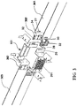
- Fig. 1 shows an adapter 101 used in a cable raceway 303 according to the invention.
- the adapter comprises: a main housing comprising a flat bottom wall and four sidewalls vertically extending from the bottom wall, a first connection part disposed on at least one sidewall for connecting the adapter to the cable raceway, a second connection part disposed on another sidewalls for connecting a distribution module to the adapter, a distribution module for connecting with cables in the adapter and introducing patch cords, and a cable management bracket disposed on the another sidewalls for managing the patch cords introduced from the distribution module.
- the main housing comprises a flat bottom wall 111 and four sidewalls vertically extending from the bottom wall, namely, a first sidewall 112 and an opposing second sidewall 113, and a third sidewall 114 and an opposing fourth sidewall 115.
- the third sidewall 114 and the fourth sidewall 115 each includes a main wall portion being vertical with respect to the first sidewall 112 and the second sidewall 113 and an extension wall portion extending from the main wall portion.
- the bottom wall 111 includes bottom wall extension portions outwardly extending at two sides. The bottom wall extension portions are respectively vertically crossed with the extension wall portions of the third sidewall 114 and the fourth sidewall to form a U-shaped configuration mating with the U-shaped cross section of the cable raceway 303.
- the first connection part 103 can be disposed on the third side wall for connecting the adapter 101 to the cable raceway 103.
- the first connection part 103 may comprise a bottom wall extension portion and the extension wall portion of the third side wall.
- the first connection part 103 further includes an elongated mounting slot 22 in the bottom wall extension portion and elongated mounting slots 24 in the extension wall portion of the third side wall.
- the second connection part 102 can be disposed on the first side wall 112, the second side wall 113 and/or the fourth side wall 115, for connecting a distribution module 201 to the adapter 101.
- the second connection part 102 can be in a form of a plurality of mounting holes.
- the second connection part 102 may include four mounting holes.
- the distribution module 201 may be a distribution module commonly used in the art. As shown in Fig. 2 , the distribution module 201 is inserted into the adapter from inner side of the first side wall, and then is removably connected by inserting four screw connectors, snap fasteners or the likes into four mounting holes of the second connection part 102 and corresponding holes in the distribution module 201. The distribution module 201 is connected with the cables in the adapter at its inner side and introduces patch cords at its outer side.
- the first side 112 is further provided with a window 32 for exposing a portion of the distribution module 201 for introducing the patch cords, thereby facilitating the introduction of the patch cords.
- the third side wall 113 may be also provided with the same mounting holes and window and may be fitted with the same distribution module 201.
- the main wall portion of the fourth sidewall 115 may be also provided with four mounting holes and may be fitted with the same distribution module 201 (see Fig. 7 ). Since a channel is formed between the extension wall portions of the fourth side wall, the portion of the fitted distribution module 201 for introducing the patch cords can be exposed, thereby facilitating the introduction of the patch cords.
- cables in the cable raceway 303 may be directly connected to one distribution module 201 within the adapter 101, and then patch cords introduced from the distribution module 201 are connected to the device or termination, thereby saving space in the machine cabinet and frame and reducing costs. Further, since there are a plurality of the distribution modules (at least two, preferable three) 201 directly mounted in the adapter, it is easy to expand the channels for communication.
- the distribution modules 201 may be copper modules or optical fiber modules mounted in the adapter 101.
- the cable management brackets 104 may be disposed on at least one end of the first side wall 112 and/or the second side wall 113 for managing the patch cords introduced from the distribution module.
- the cable management brackets 104 are respectively disposed on two ends of the first side wall 112 and the second side wall 113. That is, there are four cable management brackets 104.
- Each cable management bracket 104 may comprise a straight portion 141 and a curved portion 142 outwardly extending from the straight portion.
- the cable management bracket 104 can be welded to the end of the corresponding side wall at one end of the straight portion. Further, the cable management bracket 104 can be connected to the end of the corresponding side wall by screw connector. Other possible connection means can also be used.
- the curved portion 142 is adapted to direct the patch cords and the radius of the curved portion is able to prevent excess curve of the patch cords.
- the cable management bracket 104 may further comprise a finger portion 143 vertically and upwardly extending from an outward end of the curved portion.
- the finger portion 143 can help to prevent slippage of the patch cords from the curved portion.
- the curved portion 142 may be further provided with a plurality of connection slots through which a binding tape passes for binding the patch cords together, thereby facilitating management of the patch cords and preventing slippage of the patch cords from the curved portion.
- Fig. 5 shows an alternative cable management bracket 104'.
- the curved portion 142 is provided with multiple rows of connection slots.
- a binding tape can pass through suitable connection slots for binding the patch cords together.
- the finger portion and/or the connection slots may be provided.
- the first connection part can be disposed on the extension wall portion of the fourth side wall 115.
- the first connection part may comprise the extension wall portion of the fourth side wall 115 and the bottom wall extension portion which form the U-shaped configuration, and may also comprise elongated mounting slots 26, 28 therein.
- the cable raceway 303 may comprise corresponding elongated mounting slots 27 at its connection end.
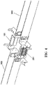
- the first connection part may be connected with the cable raceway by a coupling member 302 so that the adapter 101 at its two ends can be connected with two sections of cable raceway 303 to form a single piece, as shown in Fig. 4 .
- the coupling member 302 is in a form of U-shape which mates with the U-shaped cross section of the cable raceway 303.
- the coupling member 302 comprises a base and two legs.
- the coupling member 302 further comprises: a clamping portion 32 extending towards two sides from a top end and a bottom end of each leg of the coupling member to be adapted to clamp the extension wall portion of the side wall and the sidewall of the cable raceway; a first resilient inclined portion 34 extending towards two sides between the top end and the bottom end to be inserted into the elongated mounting slots in the extension wall portion of the side wall and the sidewall of the cable raceway; a second resilient inclined portion 36 extending towards two sides at middle of the base to be inserted into the elongated mounting slots in the bottom wall extension portion and the bottom wall of the cable raceway.
- the adapter 101 and the cable raceway 303 can be connected together by clamping the extension wall portion of the corresponding side wall and the side wall of the cable raceway with the clamping portions and by inserting the first and second resilient inclined portions into the corresponding elongated mounting holes.
- the adapter 102 can be formed as a part of the cable raceway 303.
- the adapter 101 can be used as a connection means for connecting two sections of cable raceway 303.
- Fig. 5 shows an alternative coupling member 302' and an alternative first connection 103'.
- the coupling member 302 is in a form of U-shape which mates with the U-shaped cross section of the cable raceway 303.
- the coupling member 302' also comprises a base and two legs with a curved resilient snap portion at top end thereof.
- the first connection part 103' and the cable raceway 303' do not comprise the elongated mounting slots but only comprise the extension wall portion of the corresponding side wall and the bottom wall extension portion which form the U-shaped configuration.
- the adapter and the cable raceway can be connected together by inserting the U-shaped configuration of the adapter and the connection end of the cable raceway into the coupling member 302' and by snapping the extension wall portion of the corresponding side wall and the side wall of the cable raceway from the top by the curved resilient snap portion.
- connection means can be adopted which can connect the first connection part and the cable raceway together so as to connect the adapter into the cable raceway for forming a single piece.
- the first connection part may be integrally formed with the coupling member.
- the first connection is configured to be in a form of half of the coupling member as shown in Fig. 3 for directly connecting with the cable raceway.
- the second connection part 102 can also be disposed on the main wall portion of the fourth side wall 115 so that the distribution module 201 can be fitted into the adapter as shown in Fig. 2 .
- Fig. 7 further shows an assembled perspective view of the adapter fitted with two distribution modules.
- a third connection part can be disposed on the extension wall portion of the fourth side wall 115 for connecting an end cap 304 to the adapter 101.
- the present embodiment can be adopted.
- the third connection part may be same as the structure of the first connection part 103 as shown in Fig. 3 .
- the structure of the end cap 304 may be same as a half part of the coupling member 302 as shown in Fig. 3 , except for a closed end wall.
- the end cap 304 comprises a base, two legs and a closed end wall.
- a clamping portion 52 extends towards one side from a top end and a bottom end of each leg to be adapted to clamp the extension wall portion of the fourth side wall.
- a first resilient inclined portion 54 extends towards one side between the top end and the bottom end to be inserted into the elongated mounting slots in the extension wall portion of the fourth side wall.
- a second resilient inclined portion 36 is disposed on the base and extends towards one side at middle of the base to be inserted into the elongated mounting slots in the bottom wall extension portion.
- the adapter 101 and the end cap 304 can be connected together by clamping the extension wall portion of the fourth side wall with the clamping portions and by inserting the first and second resilient inclined portions into the corresponding elongated mounting holes.
- Fig. 9 further shows an assembled perspective view of the adapter fitted with the end cap 304.
- the third connection part may be same as the structure of the first connection part 103' as shown in Fig. 5 .
- the structure of the end cap 304 may be same as a half part of the coupling member 302' as shown in Fig. 5 , except for a closed end wall.
- the end cap 304 comprises a base, a closed end wall and two legs with a curved resilient snap portion at top end of each leg.
- the third connection part do not comprise the elongated mounting slots but only comprise the extension wall portion of the fourth side wall and the bottom wall extension portion which form the U-shaped configuration.
- the adapter and the end cap 304 can be connected together by inserting the U-shaped configuration of the adapter into the end cap and by snapping the extension wall portion of the fourth side wall from the top by the curved resilient snap portion.
- a first connection part, a second connection part or a third connection part can be formed in the fourth sidewall of the adapter so that the adapted can have multiple connection applications, for example a connection with another section of cable raceway (see Figs. 3-5 ), a connection with another distribution module (see Figs. 6 and 7 ), or a connection with a end cap (see Figs. 8 and 9 ).
- the adapter according to the present invention can be fitted with a top cover 105 to prevent impurity from entering the adapter and to protect the components in the adapter.
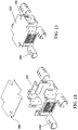
- Figures 12 and 13 respectively shows an explosive view and an assembled perspective view of the adapter according to another embodiment of the invention connected with the cable raceway.
- the housing of the adapter comprises a first sidewall and an opposing second sidewall, which together with the bottom side, form two U-shaped configurations corresponding to U-shaped cross-section of the cable raceway.
- the first sidewall and the second sidewall each is provided with at least one window for exposing a part of the distribution module.
- the at least one window may be two or four or more windows.
- the first connection part of the adapter may comprise the U-shaped configuration and elongated mounting slots therein, for connecting to the cable raceway by the coupling member 302 as shown in Fig. 3 .
- the first connection part of the adapter may only comprise the U-shaped configuration for connecting to the cable raceway by the coupling member 302' as shown in Fig. 5 .
- the adapter comprises one first connection part at two ends of the first and second side walls. On each of the first and second side walls, is provided with two second connection parts for connecting with the distribution modules.
- Figure 14 and 15 respectively show an assembled and an explosive perspective view of the adapter according to still another embodiment of the invention connected with the cable raceway.
- the housing is similar to the end cap as shown in Fig. 8 , except that the closed wall of the end is provided with at least one second connection part for mounting at least one distribution module and at least one window for exposing a part of the distribution module.
- the legs of the end cap are used as at least one first connection part for connecting with the cable raceway.
- the adapter may have other configurations, as long as it can be directly connected to the cable raceway or be connected to the cable raceway by a corresponding coupling member to be formed as a part of the cable raceway.
- one of the U-shaped configuration can form as a third connection part for connecting a end cap to the adapter 101.
- the end cap may be a half part of the coupling member 302 as shown in Fig. 3 or a half part of the coupling member 302' as shown in Fig. 5 , except for a closed end wall.
- the housing of the adapter may have other polygon structure, as long as it may provide at least one first connection part for connecting with the cable raceway and at least one second connection part for connecting with at least one distribution module.
- the invention further provides a cable distribution system comprising an adapter according to the invention, wherein the adapter can be connected with a cable raceway.
- the cable distribution system according to the invention can not only save space in the machine cabinet or frame but also easily expand channels for communication.
Landscapes
- Engineering & Computer Science (AREA)
- Architecture (AREA)
- Civil Engineering (AREA)
- Structural Engineering (AREA)
- Cable Accessories (AREA)
- Light Guides In General And Applications Therefor (AREA)
Claims (14)
- Un adaptateur (101) utilisé dans une canalisation pour câbles (303) utilisée dans du câblage pour communication de données dans l'industrie des télécommunications, l'adaptateur comprenant :un boîtier principal ;au moins une première partie de connexion (103) disposée sur le boîtier principal pour connecter l'adaptateur (101) à la canalisation pour câbles (303) ;au moins une deuxième partie de connexion (102) disposée sur le boîtier principal pour connecter au moins un module de distribution (201) à l'adaptateur (101) ; etau moins un module de distribution (201) pour se connecter avec des câbles dans l'adaptateur et introduire des cordons de raccordement, l'au moins un module de distribution (201) étant monté directement dans l'adaptateur ;dans lequelle boîtier principal comprend une paroi de fond plate (111) et une pluralité de parois latérales s'étendant verticalement à partir de la paroi de fond, ladite pluralité de parois latérales comprenant une première paroi latérale et une deuxième paroi latérale à l'opposé, qui ensemble avec la paroi de fond (111) forment deux configurations en forme de U correspondant à une coupe transversale en forme de U de la canalisation pour câbles, la première paroi latérale et la deuxième paroi latérale étant chacune pourvue d'au moins une fenêtre pour exposer une portion du module de distribution, la pluralité de parois latérales incluant également une troisième paroi latérale (114) et une quatrième paroi latérale (115) à l'opposé, les troisième et quatrième parois latérales (114, 115) incluant chacune une portion de paroi principale étant verticale par rapport à la première paroi latérale (112) et à la deuxième paroi latérale (113) et à une portion de paroi d'extension s'étendant à partir de la portion de paroi latérale principale ; la paroi de fond (111) incluant des portions d'extension de paroi de fond afin, ensemble avec les portions de paroi d'extension des troisième (114) et quatrième (115) parois latérales, de former une configuration en forme de U correspondant à la coupe transversale en forme de U de la canalisation pour câbles ;l'au moins une première partie de connexion (103) est disposée sur au moins une paroi latérale, la première partie de connexion (103) étant au moins disposée sur une des configurations en forme de U ; la première partie de connexion (103) étant au moins disposée sur la configuration en forme de U formée par la troisième paroi latérale (114) et la paroi de fond ; etl'au moins une deuxième partie de connexion (102) est disposée sur des parois latérales correspondantes, la deuxième partie de connexion (102) étant au moins disposée sur la première paroi latérale (112) et/ou la deuxième paroi latérale (113).
- L'adaptateur selon la revendication 1, l'adaptateur comprenant en outre au moins un support de gestion de câbles (104) disposé sur la paroi latérale correspondante pour gérer les cordons de raccordement introduits à partir du module de distribution.
- L'adaptateur selon la revendication 1 ou la revendication 2, dans lequel la première partie de connexion (103) est en outre disposée sur la configuration en forme de U formée par la quatrième paroi latérale (115) et la paroi de fond, dans lequel la deuxième partie de connexion (102) est en outre disposée sur la portion de paroi principale de la quatrième paroi latérale (115).
- L'adaptateur selon la revendication 1, dans lequel l'autre configuration des configurations en forme de U forme une troisième partie de connexion pour connecter un embout (304) à l'adaptateur (101).
- L'adaptateur selon la revendication 1 ou la revendication 2, dans lequel la configuration en forme de U formée par la quatrième paroi latérale (114) et la paroi de fond forme une troisième partie de connexion pour connecter un embout à l'adaptateur (101).
- L'adaptateur selon la revendication 5, dans lequel la troisième partie de connexion comprend en outre des fentes de montage allongées dans la configuration en forme de U.
- L'adaptateur selon n'importe laquelle des revendications 1 à 6, dans lequel la deuxième partie de connexion (102) comprend une pluralité de trous de montage.
- L'adaptateur selon n'importe laquelle des revendications 2 à 7, dans lequel chaque support de gestion de câbles (104) comprend une portion droite (141) et une portion courbe (142) s'étendant vers l'extérieur à partir de la portion droite.
- L'adaptateur selon la revendication 8, dans lequel chaque support de gestion de câbles (104) comprend en outre une portion languette (143) s'étendant verticalement et vers le haut à partir d'une extrémité extérieure de la portion courbe.
- L'adaptateur selon la revendication 8 ou la revendication 9, dans lequel la portion courbe (142) est pourvue d'une pluralité de fentes de connexion à travers lesquelles un ruban d'attache passe pour attacher les cordons de raccordement ensemble.
- L'adaptateur selon n'importe laquelle des revendications précédentes, l'adaptateur étant en outre pourvu d'un couvercle de dessus.
- L'adaptateur selon n'importe laquelle des revendications précédentes, dans lequel la première partie de connexion connecte l'adaptateur à la canalisation pour câbles par un élément d'accouplement.
- L'adaptateur selon la revendication 12, dans lequel l'élément d'accouplement est formé de façon solidaire avec la première partie de connexion.
- L'adaptateur selon la revendication 3, dans lequel la première partie de connexion comprend la configuration en forme de U et des fentes de connexion allongées dans celle-ci, et dans lequel la canalisation pour câbles (303) inclut des fentes de montage allongées correspondantes sur sa paroi de fond et deux parois latérales ; la première partie de connexion connectant l'adaptateur à la canalisation pour câbles par un élément d'accouplement (302), l'élément d'accouplement (302) ayant une base et deux pattes ; l'élément d'accouplement (302) comprenant en outre : une portion de serrage s'étendant respectivement vers deux côtés à partir d'une extrémité de dessus et d'une extrémité de dessous de chaque patte afin d'être adaptée pour serrer la portion de paroi d'extension de la paroi latérale et la paroi latérale de la canalisation pour câbles ; une première portion inclinée élastique (34) s'étendant vers deux côtés entre l'extrémité de dessus et l'extrémité de dessous afin d'être insérée dans les fentes de montage allongées dans la portion de paroi d'extension de la paroi latérale et la paroi latérale de la canalisation pour câbles ; une deuxième portion inclinée élastique (36) s'étendant vers deux côtés au milieu de la base devant être insérée dans les fentes de montage allongées dans la portion d'extension de paroi de fond et la paroi de fond de la canalisation pour câbles.
Applications Claiming Priority (1)
| Application Number | Priority Date | Filing Date | Title |
|---|---|---|---|
| PCT/CN2014/082164 WO2016008076A1 (fr) | 2014-07-14 | 2014-07-14 | Adaptateur pour chemin de câbles, et système de répartition de câbles |
Publications (3)
| Publication Number | Publication Date |
|---|---|
| EP3171471A1 EP3171471A1 (fr) | 2017-05-24 |
| EP3171471A4 EP3171471A4 (fr) | 2018-03-14 |
| EP3171471B1 true EP3171471B1 (fr) | 2020-11-04 |
Family
ID=55077787
Family Applications (1)
| Application Number | Title | Priority Date | Filing Date |
|---|---|---|---|
| EP14897519.6A Active EP3171471B1 (fr) | 2014-07-14 | 2014-07-14 | Adaptateur pour chemin de câbles, et système de répartition de câbles |
Country Status (7)
| Country | Link |
|---|---|
| US (1) | US10547166B2 (fr) |
| EP (1) | EP3171471B1 (fr) |
| CN (1) | CN107078484B (fr) |
| AU (1) | AU2014401308A1 (fr) |
| ES (1) | ES2838013T3 (fr) |
| MX (1) | MX394815B (fr) |
| WO (1) | WO2016008076A1 (fr) |
Families Citing this family (3)
| Publication number | Priority date | Publication date | Assignee | Title |
|---|---|---|---|---|
| WO2021247709A1 (fr) | 2020-06-02 | 2021-12-09 | Commscope Technologies Llc | Gestion de câbles dans une installation de fibre |
| CN111885050B (zh) * | 2020-07-21 | 2022-01-11 | 腾讯科技(深圳)有限公司 | 基于区块链网络的数据存储方法、装置、相关设备及介质 |
| DK180993B1 (en) * | 2022-03-07 | 2022-09-07 | Sejerslev Aps | Tray assembly, the use of the tray assembly and a method for arranging cables and tubes in the tray assembly |
Citations (4)
| Publication number | Priority date | Publication date | Assignee | Title |
|---|---|---|---|---|
| WO2006076466A2 (fr) * | 2005-01-13 | 2006-07-20 | The Wiremold Company | Canalisation modulaire avec socle et diviseur integral |
| US20080017760A1 (en) * | 2006-07-20 | 2008-01-24 | Larsen Lars R | Cable pathway patch panel rack with waterfall base |
| US7645935B1 (en) * | 2007-08-22 | 2010-01-12 | The Wiremold Company | Outlet assembly |
| US20120295483A1 (en) * | 2011-05-18 | 2012-11-22 | Ole Falk Smed | Multi-Function Power Strip |
Family Cites Families (25)
| Publication number | Priority date | Publication date | Assignee | Title |
|---|---|---|---|---|
| JPS62163505A (ja) | 1986-01-13 | 1987-07-20 | 未来工業株式会社 | 線ぴとボツクスとの連結構造 |
| FR2595513B1 (fr) | 1986-03-10 | 1994-04-08 | Legrand | Support adaptateur pour appareillage electrique |
| JP3243349B2 (ja) * | 1993-11-08 | 2002-01-07 | 松下電工株式会社 | 配線器具 |
| US5486650A (en) * | 1993-11-15 | 1996-01-23 | Hubbell Incorporated | Partition for dividing a device box |
| CN2335287Y (zh) * | 1997-06-23 | 1999-08-25 | 利阳电子股份有限公司 | 信号转接器的改良结构 |
| US5942724A (en) * | 1997-09-23 | 1999-08-24 | The Wiremold Company | Wire containment system for mounting on a wall structure |
| US5937131A (en) | 1997-11-17 | 1999-08-10 | Adc Telecommunications, Inc. | Optical cable exit trough |
| US5923753A (en) | 1997-11-17 | 1999-07-13 | Adc Telecommunications, Inc. | Optic cable exit trough with bypass |
| US6284975B1 (en) * | 1999-06-16 | 2001-09-04 | The Wiremold Company | Divider for raceway tee assembly |
| US6342675B1 (en) * | 2000-06-22 | 2002-01-29 | Hubbell Incorporated | Feed through box assembly for raceway |
| US6535683B1 (en) | 2000-10-06 | 2003-03-18 | Adc Telecommunications, Inc. | Cable exit trough with cover |
| US6866541B2 (en) | 2001-07-26 | 2005-03-15 | Panduit Corp. | Angled patch panel with cable support bar for network cable racks |
| US6756539B1 (en) * | 2003-03-20 | 2004-06-29 | Panduit Corp. | Adjustable mid-panel spillover fitting |
| KR100653330B1 (ko) | 2004-11-24 | 2006-12-01 | 주식회사 진우씨스템 | 배선덕트의 단위 모듈별 접속 구조 |
| US7462779B2 (en) * | 2005-09-08 | 2008-12-09 | Panduit Corp. | Wall mounted enclosure with rotating patch panel frame |
| US7893362B2 (en) * | 2006-06-28 | 2011-02-22 | Commscope, Inc. Of North Carolina | Smoke-resistant surface mount box for plenum space |
| US7463812B2 (en) | 2007-01-19 | 2008-12-09 | Adc Telecommunications, Inc. | Overhead cable termination arrangement |
| US7829787B2 (en) | 2007-07-09 | 2010-11-09 | Adc Telecommunications, Inc. | Telecommunications frame including an internal cable trough assembly |
| CN201210694Y (zh) * | 2008-02-26 | 2009-03-18 | 东莞市日新电线实业有限公司 | 一种信号转换器 |
| EP2297829B1 (fr) | 2008-05-20 | 2011-11-30 | Panduit Corp. | Système de branchement de câble |
| CN201204399Y (zh) * | 2008-06-06 | 2009-03-04 | 施忠巧 | 抽出式1/2单元电路分配转接器 |
| CN201490644U (zh) | 2009-07-21 | 2010-05-26 | 朱成城 | 电缆布线槽组件 |
| FR2991517B1 (fr) * | 2012-06-04 | 2014-06-20 | Gewiss France Sas | Goulotte pour chemin de cables et ensemble comprenant une telle goulotte |
| KR101396033B1 (ko) * | 2013-01-08 | 2014-05-16 | 박재원 | 케이블 배선용 입상트레이 슬리브 |
| US9312670B1 (en) * | 2013-03-09 | 2016-04-12 | Jeffrey Baldwin | Sealed cable conduit electrical box |
-
2014
- 2014-07-14 CN CN201480080578.0A patent/CN107078484B/zh not_active Expired - Fee Related
- 2014-07-14 EP EP14897519.6A patent/EP3171471B1/fr active Active
- 2014-07-14 AU AU2014401308A patent/AU2014401308A1/en not_active Abandoned
- 2014-07-14 WO PCT/CN2014/082164 patent/WO2016008076A1/fr not_active Ceased
- 2014-07-14 MX MX2017000501A patent/MX394815B/es unknown
- 2014-07-14 ES ES14897519T patent/ES2838013T3/es active Active
- 2014-07-14 US US15/326,945 patent/US10547166B2/en active Active
Patent Citations (4)
| Publication number | Priority date | Publication date | Assignee | Title |
|---|---|---|---|---|
| WO2006076466A2 (fr) * | 2005-01-13 | 2006-07-20 | The Wiremold Company | Canalisation modulaire avec socle et diviseur integral |
| US20080017760A1 (en) * | 2006-07-20 | 2008-01-24 | Larsen Lars R | Cable pathway patch panel rack with waterfall base |
| US7645935B1 (en) * | 2007-08-22 | 2010-01-12 | The Wiremold Company | Outlet assembly |
| US20120295483A1 (en) * | 2011-05-18 | 2012-11-22 | Ole Falk Smed | Multi-Function Power Strip |
Also Published As
| Publication number | Publication date |
|---|---|
| US20170271859A1 (en) | 2017-09-21 |
| EP3171471A4 (fr) | 2018-03-14 |
| CN107078484B (zh) | 2019-11-19 |
| MX394815B (es) | 2025-03-24 |
| AU2014401308A1 (en) | 2017-03-02 |
| EP3171471A1 (fr) | 2017-05-24 |
| WO2016008076A1 (fr) | 2016-01-21 |
| MX2017000501A (es) | 2017-06-20 |
| US10547166B2 (en) | 2020-01-28 |
| ES2838013T3 (es) | 2021-07-01 |
| CN107078484A (zh) | 2017-08-18 |
Similar Documents
| Publication | Publication Date | Title |
|---|---|---|
| US7963486B2 (en) | Cable management assembly with variably spaced projections | |
| EP2647095B1 (fr) | Dispositif réducteur de tension | |
| US6077113A (en) | Modular cross-connect panel for data networks | |
| EP1858265A2 (fr) | Système vertical d'agencement de cables à structure à côtes | |
| US20240264401A1 (en) | Fiber Optic Tray Systems | |
| US20040206531A1 (en) | Adjustable mid-panel spillover fitting | |
| US20140185992A1 (en) | Fiber optic module housing and fiber optic module | |
| US10547166B2 (en) | Cable channel adapter and cable distribution system | |
| US20070111585A1 (en) | Cable management device for use in connection with a power center, and cable management system comprising same | |
| US9780543B2 (en) | Support frame for structured cabling system | |
| US11502488B2 (en) | Cable management assembly for variable length cables | |
| CN108293154B (zh) | 包括用于附接插入式模块的装置的接插面板 | |
| KR101558521B1 (ko) | 투명 라벨창이 구비되는 배선 닥트 | |
| CN114025548B (zh) | 理线单元 | |
| EP2711755A2 (fr) | Dispositif de gestion de câble optique pour dispositif de distribution de câble optique | |
| KR200285747Y1 (ko) | 통신용 장비를 적재하기 위한 마운팅 랙 | |
| US20150355412A1 (en) | Conduit for Passing a Plurality of Fiber Optic Cables through a Fiber Optic Cassette Shelf | |
| KR101506515B1 (ko) | 확장성을 가진 광 분배함 | |
| KR20080108704A (ko) | 케이블 고정형 광 분배함 | |
| MX2008001573A (en) | Parking device for fiber distribution hub |
Legal Events
| Date | Code | Title | Description |
|---|---|---|---|
| STAA | Information on the status of an ep patent application or granted ep patent |
Free format text: STATUS: THE INTERNATIONAL PUBLICATION HAS BEEN MADE |
|
| PUAI | Public reference made under article 153(3) epc to a published international application that has entered the european phase |
Free format text: ORIGINAL CODE: 0009012 |
|
| STAA | Information on the status of an ep patent application or granted ep patent |
Free format text: STATUS: REQUEST FOR EXAMINATION WAS MADE |
|
| 17P | Request for examination filed |
Effective date: 20170119 |
|
| AK | Designated contracting states |
Kind code of ref document: A1 Designated state(s): AL AT BE BG CH CY CZ DE DK EE ES FI FR GB GR HR HU IE IS IT LI LT LU LV MC MK MT NL NO PL PT RO RS SE SI SK SM TR |
|
| AX | Request for extension of the european patent |
Extension state: BA ME |
|
| DAX | Request for extension of the european patent (deleted) | ||
| A4 | Supplementary search report drawn up and despatched |
Effective date: 20180213 |
|
| RIC1 | Information provided on ipc code assigned before grant |
Ipc: H02G 3/06 20060101AFI20180207BHEP Ipc: H02G 3/08 20060101ALN20180207BHEP Ipc: H02G 3/10 20060101ALI20180207BHEP Ipc: H02G 3/04 20060101ALN20180207BHEP |
|
| STAA | Information on the status of an ep patent application or granted ep patent |
Free format text: STATUS: EXAMINATION IS IN PROGRESS |
|
| 17Q | First examination report despatched |
Effective date: 20190211 |
|
| RIC1 | Information provided on ipc code assigned before grant |
Ipc: H02G 3/10 20060101ALI20200226BHEP Ipc: H02G 3/08 20060101ALN20200226BHEP Ipc: H02G 3/04 20060101ALN20200226BHEP Ipc: H02G 3/06 20060101AFI20200226BHEP |
|
| GRAP | Despatch of communication of intention to grant a patent |
Free format text: ORIGINAL CODE: EPIDOSNIGR1 |
|
| STAA | Information on the status of an ep patent application or granted ep patent |
Free format text: STATUS: GRANT OF PATENT IS INTENDED |
|
| RIC1 | Information provided on ipc code assigned before grant |
Ipc: H02G 3/08 20060101ALN20200324BHEP Ipc: H02G 3/10 20060101ALI20200324BHEP Ipc: H02G 3/06 20060101AFI20200324BHEP Ipc: H02G 3/04 20060101ALN20200324BHEP |
|
| INTG | Intention to grant announced |
Effective date: 20200406 |
|
| GRAJ | Information related to disapproval of communication of intention to grant by the applicant or resumption of examination proceedings by the epo deleted |
Free format text: ORIGINAL CODE: EPIDOSDIGR1 |
|
| REG | Reference to a national code |
Ref country code: DE Ref legal event code: R079 Ref document number: 602014072151 Country of ref document: DE Free format text: PREVIOUS MAIN CLASS: H02G0003080000 Ipc: H02G0003060000 |
|
| STAA | Information on the status of an ep patent application or granted ep patent |
Free format text: STATUS: EXAMINATION IS IN PROGRESS |
|
| GRAS | Grant fee paid |
Free format text: ORIGINAL CODE: EPIDOSNIGR3 |
|
| STAA | Information on the status of an ep patent application or granted ep patent |
Free format text: STATUS: GRANT OF PATENT IS INTENDED |
|
| GRAP | Despatch of communication of intention to grant a patent |
Free format text: ORIGINAL CODE: EPIDOSNIGR1 |
|
| INTG | Intention to grant announced |
Effective date: 20200827 |
|
| RIC1 | Information provided on ipc code assigned before grant |
Ipc: H02G 3/06 20060101AFI20200817BHEP Ipc: H02G 3/10 20060101ALI20200817BHEP Ipc: H02G 3/08 20060101ALN20200817BHEP Ipc: H02G 3/04 20060101ALN20200817BHEP |
|
| GRAA | (expected) grant |
Free format text: ORIGINAL CODE: 0009210 |
|
| STAA | Information on the status of an ep patent application or granted ep patent |
Free format text: STATUS: THE PATENT HAS BEEN GRANTED |
|
| AK | Designated contracting states |
Kind code of ref document: B1 Designated state(s): AL AT BE BG CH CY CZ DE DK EE ES FI FR GB GR HR HU IE IS IT LI LT LU LV MC MK MT NL NO PL PT RO RS SE SI SK SM TR |
|
| REG | Reference to a national code |
Ref country code: GB Ref legal event code: FG4D |
|
| REG | Reference to a national code |
Ref country code: CH Ref legal event code: EP |
|
| REG | Reference to a national code |
Ref country code: AT Ref legal event code: REF Ref document number: 1332059 Country of ref document: AT Kind code of ref document: T Effective date: 20201115 |
|
| REG | Reference to a national code |
Ref country code: DE Ref legal event code: R096 Ref document number: 602014072151 Country of ref document: DE |
|
| REG | Reference to a national code |
Ref country code: IE Ref legal event code: FG4D |
|
| REG | Reference to a national code |
Ref country code: NL Ref legal event code: MP Effective date: 20201104 |
|
| REG | Reference to a national code |
Ref country code: AT Ref legal event code: MK05 Ref document number: 1332059 Country of ref document: AT Kind code of ref document: T Effective date: 20201104 |
|
| PG25 | Lapsed in a contracting state [announced via postgrant information from national office to epo] |
Ref country code: GR Free format text: LAPSE BECAUSE OF FAILURE TO SUBMIT A TRANSLATION OF THE DESCRIPTION OR TO PAY THE FEE WITHIN THE PRESCRIBED TIME-LIMIT Effective date: 20210205 Ref country code: RS Free format text: LAPSE BECAUSE OF FAILURE TO SUBMIT A TRANSLATION OF THE DESCRIPTION OR TO PAY THE FEE WITHIN THE PRESCRIBED TIME-LIMIT Effective date: 20201104 Ref country code: FI Free format text: LAPSE BECAUSE OF FAILURE TO SUBMIT A TRANSLATION OF THE DESCRIPTION OR TO PAY THE FEE WITHIN THE PRESCRIBED TIME-LIMIT Effective date: 20201104 Ref country code: PT Free format text: LAPSE BECAUSE OF FAILURE TO SUBMIT A TRANSLATION OF THE DESCRIPTION OR TO PAY THE FEE WITHIN THE PRESCRIBED TIME-LIMIT Effective date: 20210304 Ref country code: NO Free format text: LAPSE BECAUSE OF FAILURE TO SUBMIT A TRANSLATION OF THE DESCRIPTION OR TO PAY THE FEE WITHIN THE PRESCRIBED TIME-LIMIT Effective date: 20210204 |
|
| PG25 | Lapsed in a contracting state [announced via postgrant information from national office to epo] |
Ref country code: PL Free format text: LAPSE BECAUSE OF FAILURE TO SUBMIT A TRANSLATION OF THE DESCRIPTION OR TO PAY THE FEE WITHIN THE PRESCRIBED TIME-LIMIT Effective date: 20201104 Ref country code: SE Free format text: LAPSE BECAUSE OF FAILURE TO SUBMIT A TRANSLATION OF THE DESCRIPTION OR TO PAY THE FEE WITHIN THE PRESCRIBED TIME-LIMIT Effective date: 20201104 Ref country code: IS Free format text: LAPSE BECAUSE OF FAILURE TO SUBMIT A TRANSLATION OF THE DESCRIPTION OR TO PAY THE FEE WITHIN THE PRESCRIBED TIME-LIMIT Effective date: 20210304 Ref country code: LV Free format text: LAPSE BECAUSE OF FAILURE TO SUBMIT A TRANSLATION OF THE DESCRIPTION OR TO PAY THE FEE WITHIN THE PRESCRIBED TIME-LIMIT Effective date: 20201104 Ref country code: BG Free format text: LAPSE BECAUSE OF FAILURE TO SUBMIT A TRANSLATION OF THE DESCRIPTION OR TO PAY THE FEE WITHIN THE PRESCRIBED TIME-LIMIT Effective date: 20210204 Ref country code: AT Free format text: LAPSE BECAUSE OF FAILURE TO SUBMIT A TRANSLATION OF THE DESCRIPTION OR TO PAY THE FEE WITHIN THE PRESCRIBED TIME-LIMIT Effective date: 20201104 |
|
| REG | Reference to a national code |
Ref country code: LT Ref legal event code: MG9D |
|
| PG25 | Lapsed in a contracting state [announced via postgrant information from national office to epo] |
Ref country code: HR Free format text: LAPSE BECAUSE OF FAILURE TO SUBMIT A TRANSLATION OF THE DESCRIPTION OR TO PAY THE FEE WITHIN THE PRESCRIBED TIME-LIMIT Effective date: 20201104 |
|
| PG25 | Lapsed in a contracting state [announced via postgrant information from national office to epo] |
Ref country code: LT Free format text: LAPSE BECAUSE OF FAILURE TO SUBMIT A TRANSLATION OF THE DESCRIPTION OR TO PAY THE FEE WITHIN THE PRESCRIBED TIME-LIMIT Effective date: 20201104 Ref country code: RO Free format text: LAPSE BECAUSE OF FAILURE TO SUBMIT A TRANSLATION OF THE DESCRIPTION OR TO PAY THE FEE WITHIN THE PRESCRIBED TIME-LIMIT Effective date: 20201104 Ref country code: SK Free format text: LAPSE BECAUSE OF FAILURE TO SUBMIT A TRANSLATION OF THE DESCRIPTION OR TO PAY THE FEE WITHIN THE PRESCRIBED TIME-LIMIT Effective date: 20201104 Ref country code: SM Free format text: LAPSE BECAUSE OF FAILURE TO SUBMIT A TRANSLATION OF THE DESCRIPTION OR TO PAY THE FEE WITHIN THE PRESCRIBED TIME-LIMIT Effective date: 20201104 Ref country code: CZ Free format text: LAPSE BECAUSE OF FAILURE TO SUBMIT A TRANSLATION OF THE DESCRIPTION OR TO PAY THE FEE WITHIN THE PRESCRIBED TIME-LIMIT Effective date: 20201104 Ref country code: EE Free format text: LAPSE BECAUSE OF FAILURE TO SUBMIT A TRANSLATION OF THE DESCRIPTION OR TO PAY THE FEE WITHIN THE PRESCRIBED TIME-LIMIT Effective date: 20201104 |
|
| REG | Reference to a national code |
Ref country code: DE Ref legal event code: R097 Ref document number: 602014072151 Country of ref document: DE |
|
| PG25 | Lapsed in a contracting state [announced via postgrant information from national office to epo] |
Ref country code: DK Free format text: LAPSE BECAUSE OF FAILURE TO SUBMIT A TRANSLATION OF THE DESCRIPTION OR TO PAY THE FEE WITHIN THE PRESCRIBED TIME-LIMIT Effective date: 20201104 |
|
| PLBE | No opposition filed within time limit |
Free format text: ORIGINAL CODE: 0009261 |
|
| STAA | Information on the status of an ep patent application or granted ep patent |
Free format text: STATUS: NO OPPOSITION FILED WITHIN TIME LIMIT |
|
| 26N | No opposition filed |
Effective date: 20210805 |
|
| PG25 | Lapsed in a contracting state [announced via postgrant information from national office to epo] |
Ref country code: IT Free format text: LAPSE BECAUSE OF FAILURE TO SUBMIT A TRANSLATION OF THE DESCRIPTION OR TO PAY THE FEE WITHIN THE PRESCRIBED TIME-LIMIT Effective date: 20201104 Ref country code: NL Free format text: LAPSE BECAUSE OF FAILURE TO SUBMIT A TRANSLATION OF THE DESCRIPTION OR TO PAY THE FEE WITHIN THE PRESCRIBED TIME-LIMIT Effective date: 20201104 Ref country code: AL Free format text: LAPSE BECAUSE OF FAILURE TO SUBMIT A TRANSLATION OF THE DESCRIPTION OR TO PAY THE FEE WITHIN THE PRESCRIBED TIME-LIMIT Effective date: 20201104 |
|
| PG25 | Lapsed in a contracting state [announced via postgrant information from national office to epo] |
Ref country code: SI Free format text: LAPSE BECAUSE OF FAILURE TO SUBMIT A TRANSLATION OF THE DESCRIPTION OR TO PAY THE FEE WITHIN THE PRESCRIBED TIME-LIMIT Effective date: 20201104 |
|
| REG | Reference to a national code |
Ref country code: CH Ref legal event code: PL |
|
| PG25 | Lapsed in a contracting state [announced via postgrant information from national office to epo] |
Ref country code: MC Free format text: LAPSE BECAUSE OF FAILURE TO SUBMIT A TRANSLATION OF THE DESCRIPTION OR TO PAY THE FEE WITHIN THE PRESCRIBED TIME-LIMIT Effective date: 20201104 |
|
| REG | Reference to a national code |
Ref country code: BE Ref legal event code: MM Effective date: 20210731 |
|
| PG25 | Lapsed in a contracting state [announced via postgrant information from national office to epo] |
Ref country code: LI Free format text: LAPSE BECAUSE OF NON-PAYMENT OF DUE FEES Effective date: 20210731 Ref country code: CH Free format text: LAPSE BECAUSE OF NON-PAYMENT OF DUE FEES Effective date: 20210731 |
|
| PG25 | Lapsed in a contracting state [announced via postgrant information from national office to epo] |
Ref country code: IS Free format text: LAPSE BECAUSE OF FAILURE TO SUBMIT A TRANSLATION OF THE DESCRIPTION OR TO PAY THE FEE WITHIN THE PRESCRIBED TIME-LIMIT Effective date: 20210304 Ref country code: LU Free format text: LAPSE BECAUSE OF NON-PAYMENT OF DUE FEES Effective date: 20210714 |
|
| PG25 | Lapsed in a contracting state [announced via postgrant information from national office to epo] |
Ref country code: BE Free format text: LAPSE BECAUSE OF NON-PAYMENT OF DUE FEES Effective date: 20210731 |
|
| PG25 | Lapsed in a contracting state [announced via postgrant information from national office to epo] |
Ref country code: HU Free format text: LAPSE BECAUSE OF FAILURE TO SUBMIT A TRANSLATION OF THE DESCRIPTION OR TO PAY THE FEE WITHIN THE PRESCRIBED TIME-LIMIT; INVALID AB INITIO Effective date: 20140714 |
|
| PG25 | Lapsed in a contracting state [announced via postgrant information from national office to epo] |
Ref country code: CY Free format text: LAPSE BECAUSE OF FAILURE TO SUBMIT A TRANSLATION OF THE DESCRIPTION OR TO PAY THE FEE WITHIN THE PRESCRIBED TIME-LIMIT Effective date: 20201104 |
|
| P01 | Opt-out of the competence of the unified patent court (upc) registered |
Effective date: 20230530 |
|
| PG25 | Lapsed in a contracting state [announced via postgrant information from national office to epo] |
Ref country code: MK Free format text: LAPSE BECAUSE OF FAILURE TO SUBMIT A TRANSLATION OF THE DESCRIPTION OR TO PAY THE FEE WITHIN THE PRESCRIBED TIME-LIMIT Effective date: 20201104 |
|
| PG25 | Lapsed in a contracting state [announced via postgrant information from national office to epo] |
Ref country code: MT Free format text: LAPSE BECAUSE OF FAILURE TO SUBMIT A TRANSLATION OF THE DESCRIPTION OR TO PAY THE FEE WITHIN THE PRESCRIBED TIME-LIMIT Effective date: 20201104 |
|
| PGFP | Annual fee paid to national office [announced via postgrant information from national office to epo] |
Ref country code: DE Payment date: 20240729 Year of fee payment: 11 Ref country code: IE Payment date: 20240729 Year of fee payment: 11 |
|
| PGFP | Annual fee paid to national office [announced via postgrant information from national office to epo] |
Ref country code: GB Payment date: 20240729 Year of fee payment: 11 |
|
| PGFP | Annual fee paid to national office [announced via postgrant information from national office to epo] |
Ref country code: FR Payment date: 20240725 Year of fee payment: 11 |
|
| PGFP | Annual fee paid to national office [announced via postgrant information from national office to epo] |
Ref country code: ES Payment date: 20240801 Year of fee payment: 11 |
|
| PG25 | Lapsed in a contracting state [announced via postgrant information from national office to epo] |
Ref country code: TR Free format text: LAPSE BECAUSE OF FAILURE TO SUBMIT A TRANSLATION OF THE DESCRIPTION OR TO PAY THE FEE WITHIN THE PRESCRIBED TIME-LIMIT Effective date: 20201104 |
|
| REG | Reference to a national code |
Ref country code: DE Ref legal event code: R119 Ref document number: 602014072151 Country of ref document: DE |
|
| GBPC | Gb: european patent ceased through non-payment of renewal fee |
Effective date: 20250714 |
|
| PG25 | Lapsed in a contracting state [announced via postgrant information from national office to epo] |
Ref country code: GB Free format text: LAPSE BECAUSE OF NON-PAYMENT OF DUE FEES Effective date: 20250714 |
|
| PG25 | Lapsed in a contracting state [announced via postgrant information from national office to epo] |
Ref country code: DE Free format text: LAPSE BECAUSE OF NON-PAYMENT OF DUE FEES Effective date: 20260203 |
|
| PG25 | Lapsed in a contracting state [announced via postgrant information from national office to epo] |
Ref country code: FR Free format text: LAPSE BECAUSE OF NON-PAYMENT OF DUE FEES Effective date: 20250731 |