EP3171676B1 - Dispositif de production de plasma, systeme de production de plasma et procede de production de plasma - Google Patents
Dispositif de production de plasma, systeme de production de plasma et procede de production de plasma Download PDFInfo
- Publication number
- EP3171676B1 EP3171676B1 EP15195015.1A EP15195015A EP3171676B1 EP 3171676 B1 EP3171676 B1 EP 3171676B1 EP 15195015 A EP15195015 A EP 15195015A EP 3171676 B1 EP3171676 B1 EP 3171676B1
- Authority
- EP
- European Patent Office
- Prior art keywords
- plasma generating
- generating device
- electrode
- plasma
- voltage
- Prior art date
- Legal status (The legal status is an assumption and is not a legal conclusion. Google has not performed a legal analysis and makes no representation as to the accuracy of the status listed.)
- Active
Links
Images


Classifications
-
- A—HUMAN NECESSITIES
- A61—MEDICAL OR VETERINARY SCIENCE; HYGIENE
- A61N—ELECTROTHERAPY; MAGNETOTHERAPY; RADIATION THERAPY; ULTRASOUND THERAPY
- A61N1/00—Electrotherapy; Circuits therefor
- A61N1/44—Applying ionised fluids
-
- A—HUMAN NECESSITIES
- A61—MEDICAL OR VETERINARY SCIENCE; HYGIENE
- A61B—DIAGNOSIS; SURGERY; IDENTIFICATION
- A61B18/00—Surgical instruments, devices or methods for transferring non-mechanical forms of energy to or from the body
- A61B18/04—Surgical instruments, devices or methods for transferring non-mechanical forms of energy to or from the body by heating
- A61B18/042—Surgical instruments, devices or methods for transferring non-mechanical forms of energy to or from the body by heating using additional gas becoming plasma
-
- A—HUMAN NECESSITIES
- A61—MEDICAL OR VETERINARY SCIENCE; HYGIENE
- A61L—METHODS OR APPARATUS FOR STERILISING MATERIALS OR OBJECTS IN GENERAL; DISINFECTION, STERILISATION OR DEODORISATION OF AIR; CHEMICAL ASPECTS OF BANDAGES, DRESSINGS, ABSORBENT PADS OR SURGICAL ARTICLES; MATERIALS FOR BANDAGES, DRESSINGS, ABSORBENT PADS OR SURGICAL ARTICLES
- A61L2/00—Disinfection or sterilisation of materials or objects, in general; Accessories therefor
- A61L2/02—Disinfection or sterilisation of materials or objects, in general; Accessories therefor using physical processes
- A61L2/14—Plasma, i.e. ionised gases
-
- H—ELECTRICITY
- H05—ELECTRIC TECHNIQUES NOT OTHERWISE PROVIDED FOR
- H05H—PLASMA TECHNIQUE; PRODUCTION OF ACCELERATED ELECTRICALLY-CHARGED PARTICLES OR OF NEUTRONS; PRODUCTION OR ACCELERATION OF NEUTRAL MOLECULAR OR ATOMIC BEAMS
- H05H1/00—Generating plasma; Handling plasma
- H05H1/24—Generating plasma
- H05H1/2406—Generating plasma using dielectric barrier discharges, i.e. with a dielectric interposed between the electrodes
- H05H1/2437—Multilayer systems
-
- A—HUMAN NECESSITIES
- A61—MEDICAL OR VETERINARY SCIENCE; HYGIENE
- A61L—METHODS OR APPARATUS FOR STERILISING MATERIALS OR OBJECTS IN GENERAL; DISINFECTION, STERILISATION OR DEODORISATION OF AIR; CHEMICAL ASPECTS OF BANDAGES, DRESSINGS, ABSORBENT PADS OR SURGICAL ARTICLES; MATERIALS FOR BANDAGES, DRESSINGS, ABSORBENT PADS OR SURGICAL ARTICLES
- A61L2103/00—Materials or objects being the target of disinfection or sterilisation
- A61L2103/05—Living organisms or biological materials
-
- A—HUMAN NECESSITIES
- A61—MEDICAL OR VETERINARY SCIENCE; HYGIENE
- A61L—METHODS OR APPARATUS FOR STERILISING MATERIALS OR OBJECTS IN GENERAL; DISINFECTION, STERILISATION OR DEODORISATION OF AIR; CHEMICAL ASPECTS OF BANDAGES, DRESSINGS, ABSORBENT PADS OR SURGICAL ARTICLES; MATERIALS FOR BANDAGES, DRESSINGS, ABSORBENT PADS OR SURGICAL ARTICLES
- A61L2202/00—Aspects relating to methods or apparatus for disinfecting or sterilising materials or objects
- A61L2202/10—Apparatus features
- A61L2202/11—Apparatus for generating biocidal substances, e.g. vaporisers, UV lamps
-
- H—ELECTRICITY
- H05—ELECTRIC TECHNIQUES NOT OTHERWISE PROVIDED FOR
- H05H—PLASMA TECHNIQUE; PRODUCTION OF ACCELERATED ELECTRICALLY-CHARGED PARTICLES OR OF NEUTRONS; PRODUCTION OR ACCELERATION OF NEUTRAL MOLECULAR OR ATOMIC BEAMS
- H05H1/00—Generating plasma; Handling plasma
- H05H1/24—Generating plasma
- H05H1/2406—Generating plasma using dielectric barrier discharges, i.e. with a dielectric interposed between the electrodes
- H05H1/2431—Generating plasma using dielectric barrier discharges, i.e. with a dielectric interposed between the electrodes using cylindrical electrodes, e.g. rotary drums
Definitions
- the present application relates to a plasma generating device with a high-voltage electrode and at least one outer electrode. Furthermore, the present invention relates to a plasma generation system with a plurality of plasma generation devices according to the invention, and a method for generating plasma by means of a plasma generation device according to the invention or a plasma generation system according to the invention.
- the plasma generating device is used in particular for flat, antimicrobial treatment of moist surfaces and thus offers a possibility of antimicrobial wound treatment in a moist environment by means of special atmospheric pressure plasma sources.
- Atmospheric pressure plasma sources can be used for medical, dental or cosmetic purposes.
- Conventional plasma generating devices provide a superposition of jet plasmas for covering an area. Different jet nozzle geometries are used.
- a dielectric barrier discharge is usually realized with such flat-type devices.
- SBD dielectrically impeded surface discharge
- VBD dielectric barrier volume discharge
- Such devices are usually made of a relatively solid or rigid base material for reasons of strength. An adaptation to certain topographies is therefore only possible to a limited extent.
- plasma generating devices which are designed for use in the medical field are subject to relatively strict regulations with regard to safety against an impending high voltage resulting from the applied voltage Risk of injury and compliance with the guidelines for electromagnetic compatibility (EMC).
- EMC electromagnetic compatibility
- a flat plasma generating device is, for example, from the WO 2011/023478 A1 known.
- This previously known device is a cuff for the treatment of human or animal skin with the aid of a cold atmospheric pressure plasma.
- the cuff consists of a high voltage electrode, an insulating elastomer, a dielectric and a grounded electrode.
- the flat high-voltage electrode is limited on the one hand by a flat, insulating elastomer and on the other hand by a flat dielectric.
- the high-voltage electrode, the insulating elastomer, the dielectric and the electrode are flexible and can be placed on any curved surface.
- WO 2013/167693 A1 Another plasma generating device is in the WO 2013/167693 A1 disclosed. This also discloses a device for treating areas of human or animal surfaces by means of a cold atmospheric pressure plasma by generating a dielectric barrier surface discharge.
- This plasma generating device WO 2013/167693 A1 consists of a wire-shaped high-voltage electrode with an adjacent earthed electrode. For the dielectric barrier surface discharge, the high-voltage electrode is covered with a dielectric, which forms a flexible unit.
- the grounded electrode consists of a conductive, textile material. The plasma generating device thus adapts to the contour of the body areas to be treated.
- the use of the above-mentioned plasma generation devices is disadvantageous for wound healing of biological tissues in a moist environment.
- the devices of the WO 2011/023478 A1 as well as the WO 2013/167693 A1 are based on the generation of a dielectric barrier surface discharge. This type of generation is significantly impaired or even completely suppressed by high moisture on the surface of the dielectric.
- FIG WO 2011/076193 A1 A plasma generating device based on a dielectric barrier volume discharge is shown in FIG WO 2011/076193 A1 disclosed.
- the device of the WO 2011/076193 A1 consists of a flat high-voltage electrode, which is delimited on the front and on the back by a flat dielectric. This electrode arrangement is flexible to the Customizable contour of the surface.
- the surface of the dielectric on the front is shaped by knobs with an equidistant height.
- a dielectrically impeded volume discharge is generated in the air duct areas between the knobs.
- the use of the surface to be treated as a grounded counter electrode has the disadvantage of uncontrollable or indefinable surface effects on the biological tissue to be treated.
- the knobs serving as spacers lie directly on the wound to be treated and cause unwanted irritation or grid-shaped decontamination.
- WO 2010/138102 A1 discloses a plasma generating device according to the preamble of claim 1.
- the plasma generation devices with flat atmospheric pressure plasma sources known from the prior art have disadvantages for medical use.
- the use of atmospheric pressure plasma sources for medical, dental or cosmetic purposes is only possible if compliance with the guidelines for electromagnetic compatibility (EMC) can be guaranteed.
- EMC electromagnetic compatibility
- the interference radiation from the plasma source itself can no longer be neglected; the necessary EMC requirements are not met.
- the present invention is based on the object of providing a plasma generating device, a plasma generating system and a method for generating plasma, with which treatment of surfaces, in particular disinfection or sterilization, can be carried out in a simple, cost-effective, safety-friendly and flexible manner of surfaces such. B. also of biological tissue is possible.
- the plasma generating device is used in particular to generate an atmospheric pressure plasma for the antimicrobial treatment of moist surfaces.
- the plasma generating device comprises a high-voltage electrode and at least one outer electrode, the high-voltage electrode being arranged at least in a coordinate direction between line material of at least one outer electrode.
- the high-voltage electrode is covered with a dielectric at least on a side facing an outer electrode.
- the high-voltage electrode may be completely covered with a dielectric.
- Between the At least one spacer element is arranged over the longitudinal extension of the respective outer electrode and the high-voltage electrode, which at least in the area of its arrangement electrically insulates the respective outer electrode from the high-voltage electrode and positions it at a constant distance.
- the line material of the outer electrode which is opposite the high-voltage electrode in at least one coordinate direction, serves as the actual outer electrode when a suitable electrical voltage is applied to the plasma generating device.
- the dielectric is preferably not only present on the side of the high-voltage electrode facing the respective outer electrode, but encloses the high-voltage electrode provided with it.
- the spacer element or the arrangement of a plurality of spacer elements results in an essentially equidistant arrangement of the electrodes with respect to one another. This results in the possibility of generating a dielectrically impeded volume discharge which is considerably more stable than in a highly humid environment, so that the plasma generating device according to the invention can be used particularly advantageously on wounds or biological tissues.
- a substantial reduction in the electromagnetic interference radiation emitted by the plasma source is achieved by the outer electrode or outer electrodes arranged on both sides of the high-voltage electrode.
- the high-voltage electrode must be designed for the high-voltage (HV) range, namely for a voltage of at least 1 kV.
- the dielectric of the high-voltage electrode is designed for twice the dielectric strength (that is to say at least 2 kV).
- the plasma generating device can be set up for a voltage range from 1 kV up to 25 kV, at a frequency of the AC voltage of 1 kHz kilohertz up to 1 Mhz, and the control can take place with a sine, square or triangular signal as well as in a pulsed manner.
- the outer electrode or outer electrodes are grounded.
- the plasma generating device it comprises a first outer electrode and a second outer electrode, the high-voltage electrode, also referred to as the inner electrode, being arranged between the two outer electrodes.
- the high-voltage electrode is covered with a dielectric on the sides facing the two outer electrodes.
- the high-voltage electrode can be designed as a line element, the ratio of the length to the diameter of which is at least 10.
- a thin conduction element can be an insulated thin wire or an insulated, electrically conductive thread.
- the high-voltage electrode can be designed as an insulated wire, the insulation simultaneously forming the dielectric.
- the high-voltage electrode has a meandering or spiral course.
- the high-voltage electrode and / or the outer electrode or outer electrodes as an electrically conductive textile material in the form of a braid, woven fabric, knitted fabric or knitted fabric or else a sewing knitted fabric, non-woven fabric or felt or a combination of these textile materials, the material used Is metal or just a metal coating and in the case of the high voltage electrode this material is coated with a dielectric.
- the outer electrode is designed as an electrically conductive film.
- the film is in particular perforated and / or structured.
- the high-voltage electrode can also be designed as such a film coated with a dielectric.
- the respective material which forms the high-voltage electrode and also the outer electrode or outer electrodes and possibly also the dielectric, insulation and the spacing elements can have an elastic modulus of at most 1 x 10 9 N / m 2 , in particular an elastic modulus between 0.1 x 10 9 N / m 2 and 0.5 x10 9 N / m 2 , so that the entire device also has this elastic modulus and thus a very low bending and / or torsional stiffness.
- the use of elastic or flexible materials allows the plasma generation device to be flexibly adapted to a wide variety of topographies.
- the outer electrode is designed as a gas-permeable and flexible electrode including the high-voltage electrode, such as, for. B. as a metal mesh or another electrically conductive, textile material or a perforated, electrically conductive elastomer film or an elastomer film coated with an electrically conductive material, such as. B. a silicone film.
- the high-voltage electrode such as, for. B. as a metal mesh or another electrically conductive, textile material or a perforated, electrically conductive elastomer film or an elastomer film coated with an electrically conductive material, such as. B. a silicone film.
- the outer electrode is grounded and can also be a tube made of a perforated or woven conductive material or of spirally arranged thin stainless steel.
- the outer electrodes used in the plasma generating device according to the invention are conductively connected to one another.
- the plasma generating device has a plurality of spacer elements which are designed as insulating pieces which at least partially enclose the high-voltage electrode.
- spacers also called spacers, can, for. B. pieces of silicone tubing.
- one spacer element or also a plurality of spacer elements enclose the high-voltage electrode over its entire course.
- the spacer element is flat. This means that the spacer element extends essentially in a straight plane, so that it separates the outer electrodes, which preferably also extend in straight, flat planes, and the high-voltage electrode accommodated between them.
- the spacer element is realized by a perforated and / or structured gas-permeable, preferably area-covering film made of an electrically non-conductive elastomer.
- a perforated and / or structured gas-permeable, preferably area-covering film made of an electrically non-conductive elastomer.
- Such film such as. B. a silicon foil, can also be used as a dielectric, a wire-shaped high voltage electrode, e.g. is also present as braid, fabric, knitted fabric or knitted fabric, is embedded in this film.
- Such a film can have openings so that the film serving as a dielectric has a gas permeability.
- the openings can be made by perforation.
- the film should have this configuration in particular if the film is designed to cover the entire surface between electrodes.
- the spacer element is designed as a braid, woven fabric, knitted fabric or knitted fabric.
- openings are integrated in the spacer element.
- punctiform or grid-shaped coatings are produced on such a spacer element in order to be able to maintain the distance between the electrodes required for a dielectrically impeded volume discharge.
- the plasma generating device comprises a voltage supply unit which is set up to apply a low to high frequency high voltage between the outer electrode or the outer electrodes and the high voltage electrode.
- the supply lines and connections of the lines to the electrodes are in the documents WO2011023478A1 such as WO2013167693A1 taught.
- a general embodiment of the plasma generating device according to the invention thus consists in the fact that the plasma generating device is essentially flat, with a flat high-voltage electrode being sandwiched by two flat outer electrodes.
- a further embodiment consists of a rod-shaped or tubular design, an elongated high-voltage electrode being surrounded by a helical or screw-shaped outer electrode.
- an elongated high-voltage electrode is surrounded by a tubular outer electrode made of a gas-permeable, electrically conductive material. If flexible material is used in these embodiments, these can be arranged in a spiral or meandering shape, so that an adaptation to certain topographies is also possible in these cases.
- spacer elements are arranged between the high-voltage electrode and the material of the outer electrode, so that there is a distance between the high-voltage electrode and the outer electrode in order to realize a dielectrically impeded volume discharge.
- the plasma generation device can comprise a gas-permeable wound dressing which is to be positioned between biological tissue and the plasma generation device during wound treatment.
- a wound dressing can be a thin, relatively wide-meshed textile wound dressing (e.g. sterile gauze). This prevents the plasma source from coming into direct contact with the wound and from causing unwanted irritation or contamination of the wound, as is the case with the direct application of non-sterile plasma generating devices.
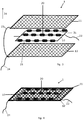
- the Figure 1 shows a first embodiment of a plasma generating device 1 in an exploded view.
- the plasma generating device 1 comprises a high-voltage electrode 10 surrounding a surface 30. In both directions of the normal to this enclosed surface 30 there is an outer electrode 11, 12 in each case.
- the two outer electrodes 11, 12 are connected to one another via an electrical connection 23.
- the high-voltage electrode 10 is designed as a wire in this example and is fed by the connecting line 22.
- the two outer electrodes 11, 12 are designed as metal mesh and are grounded via the ground cable 24.
- the high-voltage electrode 10 is encased with a dielectric 21 for a dielectrically impeded volume discharge.
- FIG. 3 Another embodiment in the exploded view shows Figure 3 .
- the flat high-voltage electrode 10 is bounded by a flat outer electrode 11, 12 in both directions of the normal to the surface 30 enclosed by the high-voltage electrode 10.
- the outer electrodes 11, 12 are also made of a metal mesh. Both outer electrodes 11, 12 are connected to one another by the electrical connection 23 and grounded via the ground cable 24.
- the Figure 4 shows the embodiment of the plasma generating device 1 in the applicable form.
- FIG Figure 5 An example of a linear embodiment of a plasma generating device according to the invention is shown in FIG Figure 5 .
- the wire-shaped high-voltage electrode 10 is covered with a dielectric 21.
- the tubular outer electrode 11 surrounds the high-voltage electrode 10 and is grounded via the ground cable 24.
- the equidistant distance 32 required for the dielectrically impeded volume discharge is given by the spacer elements 20.
- the atmospheric pressure plasma 33 generated for the dielectrically impeded volume discharge is located in the volume between the spacer elements 20, the grounded outer electrode 11 and the dielectric 21. From the coordinate direction 34 shown, it can be seen that the high-voltage electrode 10 at least in the coordinate direction 34 between the conductive material of the outer electrode 11 is arranged.
- FIG Figure 6 A further embodiment of the linear plasma generating device 1 is shown in FIG Figure 6 shown.
- the linear high-voltage electrode 10, which is coated with a dielectric 21, is surrounded by a spiral-shaped outer electrode 11. This spiral-shaped outer electrode 11 is grounded via the ground cable 24.
- the atmospheric pressure plasma 33 is generated in the spaces delimited by the outer electrode 11, the high-voltage electrode 10 and the individual spacer elements 20.
- a plasma generation system can be seen which has a plurality of plasma generation devices, in particular for the large-area treatment of surfaces.
- a plurality of plasma generation devices 1 are connected to one another in a cascade shape in an angular shape.
- the connections shown between the individual plasma generating devices 1 lead on the one hand to the high voltage, which is connected to the connecting line 22, and, on the other hand, to an earthed connection which is connected to the ground cable 24.
- ⁇ b> List of reference symbols ⁇ /b> Plasma generating device 1 High voltage electrode 10th First outer electrode 11 Second outer electrode 12 Spacer 20th dielectric 21st Connecting cable 22 Electrical connection 23 Ground cable 24th free section 25th Enclosed area 30th Parallel section 31 distance 32 Atmospheric pressure plasma 33 Coordinate direction 34
Landscapes
- Health & Medical Sciences (AREA)
- Engineering & Computer Science (AREA)
- Plasma & Fusion (AREA)
- Physics & Mathematics (AREA)
- Life Sciences & Earth Sciences (AREA)
- Animal Behavior & Ethology (AREA)
- General Health & Medical Sciences (AREA)
- Public Health (AREA)
- Veterinary Medicine (AREA)
- Surgery (AREA)
- Spectroscopy & Molecular Physics (AREA)
- Epidemiology (AREA)
- Nuclear Medicine, Radiotherapy & Molecular Imaging (AREA)
- Biomedical Technology (AREA)
- Heart & Thoracic Surgery (AREA)
- Medical Informatics (AREA)
- Molecular Biology (AREA)
- Otolaryngology (AREA)
- Radiology & Medical Imaging (AREA)
- Plasma Technology (AREA)
- Electrotherapy Devices (AREA)
Claims (13)
- Dispositif générateur de plasma (1)
comprenant une électrode à haute tension (10) ainsi qu'au moins une électrode extérieure (11, 12), dans lequel l'électrode à haute tension (10) est disposée au moins dans un axe de coordonnées (34) entre le matériau conducteur d'au moins une électrode extérieure (11, 12) et l'électrode à haute tension (10) est couverte d'un diélectrique (21) au moins sur une face tournée vers une électrode extérieure (11, 12) du dispositif générateur de plasma (1), et dans lequel au moins un élément d'écartement (20) est présent entre l'électrode extérieure respective (11, 12) et l'électrode à haute tension (10) sur leur extension longitudinale, lequel isole électriquement l'électrode extérieure respective (11,12) de l'électrode à haute tension (10) au moins dans la zone de son agencement et lequel positionne l'électrode extérieure respective (11, 12) à une distance constante de l'électrode à haute tension (10), caractérisé en ce que l'élément d'écartement (20) est conçu de manière plane et que l'élément d'écartement (20) est un film perforé et/ou structuré perméable aux gaz à base d'un élastomère électriquement non conducteur. - Dispositif générateur de plasma selon la revendication 1, caractérisé en ce que le dispositif générateur de plasma (1) comprend une première électrode extérieure (11) et une seconde électrode extérieure (12), dans lequel l'électrode à haute tension (10) est disposée entre les deux électrodes extérieures (11,12).
- Dispositif générateur de plasma selon l'une quelconques des revendications précédentes, caractérisé en ce que l'électrode à haute tension (10) est réalisée sous la forme d'un fil métallique.
- Dispositif générateur de plasma selon l'une quelconque des revendications précédentes, caractérisé en ce que l'électrode à haute tension (10) présente un parcours en forme de spirale ou de méandre.
- Dispositif générateur de plasma selon l'une quelconque des revendications 1 à 3, caractérisé en ce que l'électrode à haute tension (10) existe sous la forme d'un treillis, d'une toile, d'un tissu à mailles ou d'un tricot.
- Dispositif générateur de plasma selon l'une quelconque des revendications précédentes, caractérisé en ce que l'électrode extérieure (11, 12) existe sous la forme d'un treillis, d'une toile, d'un tissu à mailles ou d'un tricot.
- Dispositif générateur de plasma selon l'une quelconque des revendications 1 à 5, caractérisé en ce que l'électrode extérieure (11 et 12) est constituée d'un film électriquement conducteur, notamment d'un film perforé et/ou structuré.
- Dispositif générateur de plasma selon l'une quelconque des revendications précédentes, caractérisé en ce que le dispositif générateur de plasma (1) présente plusieurs éléments d'écartement (20), qui sont réalisés sous la forme de pièces isolantes entourant ou recouvrant l'électrode à haute tension (10) au moins par endroits.
- Dispositif générateur de plasma selon l'une quelconque des revendications précédentes, caractérisé en ce que le film présente des ouvertures.
- Dispositif générateur de plasma selon l'une quelconque des revendications 1 à 9, caractérisé en ce que l'élément d'écartement (20) est constitué d'un treillis, d'une toile, d'un tissu à mailles ou d'un tricot.
- Dispositif générateur de plasma selon l'une quelconque des revendications précédentes, caractérisé en ce que le dispositif générateur de plasma (1) présente une unité d'alimentation électrique, qui est ajustée afin d'appliquer une haute tension de basse à haute fréquence entre l'électrode extérieure et l'électrode à haute tension.
- Système générateur de plasma destiné notamment à traiter des surfaces très étendues, comprenant plusieurs dispositifs générateurs de plasma (1) selon l'une quelconques des revendications 1 à 11 ainsi qu'une ou plusieurs unités d'alimentation électrique, qui peuvent être ou sont reliées électriquement aux dispositifs générateurs de plasma (1).
- Procédé servant à générer du plasma, au cours duquel un dispositif générateur de plasma selon l'une quelconques des revendications 1 à 11 ou aussi un système générateur de plasma selon la revendication 12 est mis à disposition et une haute tension électrique est appliquée sur l'électrode à haute tension et sur au moins une électrode extérieure.
Priority Applications (5)
| Application Number | Priority Date | Filing Date | Title |
|---|---|---|---|
| DK15195015.1T DK3171676T3 (da) | 2015-11-17 | 2015-11-17 | Plasma generende indretning, plasma genererende system og metode til generering af plasma |
| EP15195015.1A EP3171676B1 (fr) | 2015-11-17 | 2015-11-17 | Dispositif de production de plasma, systeme de production de plasma et procede de production de plasma |
| PT151950151T PT3171676T (pt) | 2015-11-17 | 2015-11-17 | Dispositivo para gerar plasma, sistema para gerar plasma e método para gerar plasma |
| ES15195015T ES2806033T3 (es) | 2015-11-17 | 2015-11-17 | Dispositivo para generar plasma, sistema para generar plasma y método para generar plasma |
| US15/352,630 US10307606B2 (en) | 2015-11-17 | 2016-11-16 | Device for generating plasma, system for generating plasma and method for generating plasma |
Applications Claiming Priority (1)
| Application Number | Priority Date | Filing Date | Title |
|---|---|---|---|
| EP15195015.1A EP3171676B1 (fr) | 2015-11-17 | 2015-11-17 | Dispositif de production de plasma, systeme de production de plasma et procede de production de plasma |
Publications (2)
| Publication Number | Publication Date |
|---|---|
| EP3171676A1 EP3171676A1 (fr) | 2017-05-24 |
| EP3171676B1 true EP3171676B1 (fr) | 2020-06-24 |
Family
ID=54601644
Family Applications (1)
| Application Number | Title | Priority Date | Filing Date |
|---|---|---|---|
| EP15195015.1A Active EP3171676B1 (fr) | 2015-11-17 | 2015-11-17 | Dispositif de production de plasma, systeme de production de plasma et procede de production de plasma |
Country Status (5)
| Country | Link |
|---|---|
| US (1) | US10307606B2 (fr) |
| EP (1) | EP3171676B1 (fr) |
| DK (1) | DK3171676T3 (fr) |
| ES (1) | ES2806033T3 (fr) |
| PT (1) | PT3171676T (fr) |
Families Citing this family (19)
| Publication number | Priority date | Publication date | Assignee | Title |
|---|---|---|---|---|
| DE202009011521U1 (de) * | 2009-08-25 | 2010-12-30 | INP Greifswald Leibniz-Institut für Plasmaforschung und Technologie e. V. | Plasma-Manschette |
| DE102012207750A1 (de) * | 2012-05-09 | 2013-11-28 | Leibniz-Institut für Plasmaforschung und Technologie e.V. | Vorrichtung zur plasmabehandlung von menschlichen, tierischen oder pflanzlichen oberflächen, insbesondere von haut oder schleimhautarealen |
| US10646604B2 (en) * | 2016-02-04 | 2020-05-12 | Rutgers, The State University Of New Jersey | Flexible plasma applicators based on fibrous layers |
| US11684686B2 (en) * | 2016-02-04 | 2023-06-27 | Rutgers, The State University Of New Jersey | Flexible plasma applicators based on fibrous layers |
| DE102017100192A1 (de) * | 2017-01-06 | 2018-07-12 | Cinogy Gmbh | Permanente Wundauflage mit Plasmaelektrode |
| KR101813558B1 (ko) * | 2017-04-12 | 2018-01-03 | 주식회사 서린메디케어 | 프락셔널 플라즈마를 이용한 피부 치료장치 |
| DE102017111902B4 (de) * | 2017-05-31 | 2020-12-31 | Cinogy Gmbh | Flächige Auflageanordnung |
| KR102037148B1 (ko) * | 2017-09-18 | 2019-11-26 | 국방과학연구소 | 위성형 유연 플라즈마 발생장치 |
| KR101920849B1 (ko) | 2017-10-23 | 2018-11-21 | 국방과학연구소 | 플라즈마 직물과 이의 제조 장치 및 제조 방법 |
| CN112136366B (zh) | 2018-03-23 | 2024-04-09 | 冷等离子技术有限公司 | 等离子体施加器 |
| US12496456B2 (en) | 2018-03-23 | 2025-12-16 | Coldplasmatech Gmbh | Plasma applicator |
| CN109688689A (zh) * | 2019-02-20 | 2019-04-26 | 北京卓昱科技有限公司 | 一种宽间隙电子诱导等离子发生器 |
| US11984309B1 (en) * | 2020-05-29 | 2024-05-14 | Microplasma Systems, Llc | Non-radioactive plasma ion source |
| NL2027148B1 (en) * | 2020-12-17 | 2022-07-11 | Plasmacure B V | Treatment pad for a dielectric barrier discharge plasma treatment |
| PL243915B1 (pl) | 2021-01-14 | 2023-10-30 | Siec Badawcza Lukasiewicz Inst Mikroelektroniki I Fotoniki | Układ elektryczny samodezynfekującej klawiatury dotykowej |
| WO2022243543A1 (fr) * | 2021-05-20 | 2022-11-24 | Neutronstar Systems Ug | Système de gestion thermique pour un propulseur spatial |
| CN117295220A (zh) * | 2023-01-03 | 2023-12-26 | 珠海市德邦电器工程有限公司 | 一种低温等离子发生装置 |
| CN116059427B (zh) * | 2023-02-22 | 2024-07-12 | 西安电子科技大学 | 一种医疗废弃物处理系统 |
| WO2024192184A1 (fr) * | 2023-03-14 | 2024-09-19 | TellaPure, LLC | Procédés et appareil pour générer un plasma à pression atmosphérique à basse température avec des paramètres variables |
Family Cites Families (10)
| Publication number | Priority date | Publication date | Assignee | Title |
|---|---|---|---|---|
| DE1130928B (de) * | 1960-11-17 | 1962-06-07 | Hydrawerk Ag | Elektrolytkondensator mit verkleinertem Kapazitaetsvolumen |
| KR100724516B1 (ko) * | 2003-02-12 | 2007-06-04 | 니뽄 가이시 가부시키가이샤 | 플라즈마 반응기 및 그 제조 방법 |
| US20060013397A1 (en) * | 2004-07-13 | 2006-01-19 | International Business Machines Corporation | Channel adapter managed trusted queue pairs |
| CN1839996A (zh) * | 2006-01-12 | 2006-10-04 | 上海现代中医药技术发展有限公司 | 一种治疗慢性肝病的中药复方制剂及其制备方法 |
| US9288886B2 (en) * | 2008-05-30 | 2016-03-15 | Colorado State University Research Foundation | Plasma-based chemical source device and method of use thereof |
| DE202009011521U1 (de) | 2009-08-25 | 2010-12-30 | INP Greifswald Leibniz-Institut für Plasmaforschung und Technologie e. V. | Plasma-Manschette |
| DE102009060627B4 (de) | 2009-12-24 | 2014-06-05 | Cinogy Gmbh | Elektrodenanordnung für eine dielektrisch behinderte Plasmabehandlung |
| DE102011105713B4 (de) * | 2011-06-23 | 2014-06-05 | Cinogy Gmbh | Elektrodenanordnung für eine dielektrisch behinderte Gasentladung |
| DE102012207750A1 (de) * | 2012-05-09 | 2013-11-28 | Leibniz-Institut für Plasmaforschung und Technologie e.V. | Vorrichtung zur plasmabehandlung von menschlichen, tierischen oder pflanzlichen oberflächen, insbesondere von haut oder schleimhautarealen |
| DE102013203648A1 (de) * | 2013-03-04 | 2014-09-04 | INP Greifswald Leibniz-Institut für Plasmaforschung und Technologie e. V. | Verfahren und vorrichtung zur plasmabehandlung von hohlkörpern |
-
2015
- 2015-11-17 DK DK15195015.1T patent/DK3171676T3/da active
- 2015-11-17 EP EP15195015.1A patent/EP3171676B1/fr active Active
- 2015-11-17 ES ES15195015T patent/ES2806033T3/es active Active
- 2015-11-17 PT PT151950151T patent/PT3171676T/pt unknown
-
2016
- 2016-11-16 US US15/352,630 patent/US10307606B2/en active Active
Non-Patent Citations (1)
| Title |
|---|
| None * |
Also Published As
| Publication number | Publication date |
|---|---|
| DK3171676T3 (da) | 2020-07-27 |
| US10307606B2 (en) | 2019-06-04 |
| ES2806033T3 (es) | 2021-02-16 |
| PT3171676T (pt) | 2020-08-24 |
| US20170136252A1 (en) | 2017-05-18 |
| EP3171676A1 (fr) | 2017-05-24 |
Similar Documents
| Publication | Publication Date | Title |
|---|---|---|
| EP3171676B1 (fr) | Dispositif de production de plasma, systeme de production de plasma et procede de production de plasma | |
| EP3079729B1 (fr) | Dispositif pour traiter des plaies | |
| EP3051926B1 (fr) | Dispositif de production de plasma, systeme de production de plasma, procede de production de plasma et procede de desinfection de surfaces | |
| EP2163143B1 (fr) | Dispositif pour le traitement de surfaces à l'aide d'un plasma généré au moyen d'une électrode par une décharge de gaz à barrière diélectrique par le biais d'un diélectrique solide | |
| EP3079765B1 (fr) | Dispositif pour traiter des plaies | |
| EP3021875B1 (fr) | Système de réduction des germes par plasma | |
| DE102012015483B3 (de) | Elektrodenanordnung für eine Plasmabehandlung und Vorrichtung zur Herstellung einer transkutanen Verbindung | |
| EP2362755A1 (fr) | Procédé de traitement d'une matière biologique contenant des cellules vivantes | |
| DE102011001416A1 (de) | Plasmabehandlungseinrichtung und Verfahren zum Betreiben der Plasmabehandlungseinrichtung | |
| EP2848097A1 (fr) | Dispositif pour traiter au plasma des surfaces humaines, animales ou végétales, en particulier la peau ou des zones de muqueuse | |
| DE102012103362A1 (de) | Plasma-Behandlungsgerät | |
| DE102019006536B3 (de) | Vorrichtung und Verfahren zur Haut- und insbesondere Wundbehandlung unter Verwendung von Plasma | |
| EP3329747B1 (fr) | Agencement d'électrodes et dispositif de traitement au plasma pour un traitement de surface d'un corps | |
| EP3148464B1 (fr) | Dispositif pour la décontamination biologique d'accès percutanés et procédé associé | |
| DE102016205821B4 (de) | Plasmaquelle zur Wundbehandlung | |
| EP3429640B1 (fr) | Dispositif et système de traitement antimicrobien | |
| WO2012136370A1 (fr) | Installation à plasma | |
| WO2000074105A1 (fr) | Tube a rayons x et catheter muni d'un tel tube |
Legal Events
| Date | Code | Title | Description |
|---|---|---|---|
| PUAI | Public reference made under article 153(3) epc to a published international application that has entered the european phase |
Free format text: ORIGINAL CODE: 0009012 |
|
| STAA | Information on the status of an ep patent application or granted ep patent |
Free format text: STATUS: THE APPLICATION HAS BEEN PUBLISHED |
|
| AK | Designated contracting states |
Kind code of ref document: A1 Designated state(s): AL AT BE BG CH CY CZ DE DK EE ES FI FR GB GR HR HU IE IS IT LI LT LU LV MC MK MT NL NO PL PT RO RS SE SI SK SM TR |
|
| AX | Request for extension of the european patent |
Extension state: BA ME |
|
| STAA | Information on the status of an ep patent application or granted ep patent |
Free format text: STATUS: REQUEST FOR EXAMINATION WAS MADE |
|
| 17P | Request for examination filed |
Effective date: 20171123 |
|
| RBV | Designated contracting states (corrected) |
Designated state(s): AL AT BE BG CH CY CZ DE DK EE ES FI FR GB GR HR HU IE IS IT LI LT LU LV MC MK MT NL NO PL PT RO RS SE SI SK SM TR |
|
| STAA | Information on the status of an ep patent application or granted ep patent |
Free format text: STATUS: EXAMINATION IS IN PROGRESS |
|
| 17Q | First examination report despatched |
Effective date: 20191212 |
|
| GRAP | Despatch of communication of intention to grant a patent |
Free format text: ORIGINAL CODE: EPIDOSNIGR1 |
|
| STAA | Information on the status of an ep patent application or granted ep patent |
Free format text: STATUS: GRANT OF PATENT IS INTENDED |
|
| INTG | Intention to grant announced |
Effective date: 20200325 |
|
| GRAS | Grant fee paid |
Free format text: ORIGINAL CODE: EPIDOSNIGR3 |
|
| GRAA | (expected) grant |
Free format text: ORIGINAL CODE: 0009210 |
|
| STAA | Information on the status of an ep patent application or granted ep patent |
Free format text: STATUS: THE PATENT HAS BEEN GRANTED |
|
| RAP1 | Party data changed (applicant data changed or rights of an application transferred) |
Owner name: LEIBNIZ-INSTITUT FUER PLASMAFORSCHUNG UND TECHNOLOGIE E.V. |
|
| AK | Designated contracting states |
Kind code of ref document: B1 Designated state(s): AL AT BE BG CH CY CZ DE DK EE ES FI FR GB GR HR HU IE IS IT LI LT LU LV MC MK MT NL NO PL PT RO RS SE SI SK SM TR |
|
| REG | Reference to a national code |
Ref country code: GB Ref legal event code: FG4D Free format text: NOT ENGLISH |
|
| REG | Reference to a national code |
Ref country code: CH Ref legal event code: EP |
|
| REG | Reference to a national code |
Ref country code: DE Ref legal event code: R096 Ref document number: 502015012848 Country of ref document: DE |
|
| REG | Reference to a national code |
Ref country code: AT Ref legal event code: REF Ref document number: 1285215 Country of ref document: AT Kind code of ref document: T Effective date: 20200715 |
|
| REG | Reference to a national code |
Ref country code: NO Ref legal event code: T2 Effective date: 20200624 Ref country code: FI Ref legal event code: FGE |
|
| REG | Reference to a national code |
Ref country code: IE Ref legal event code: FG4D Free format text: LANGUAGE OF EP DOCUMENT: GERMAN |
|
| REG | Reference to a national code |
Ref country code: DK Ref legal event code: T3 Effective date: 20200722 |
|
| REG | Reference to a national code |
Ref country code: PT Ref legal event code: SC4A Ref document number: 3171676 Country of ref document: PT Date of ref document: 20200824 Kind code of ref document: T Free format text: AVAILABILITY OF NATIONAL TRANSLATION Effective date: 20200810 |
|
| REG | Reference to a national code |
Ref country code: SE Ref legal event code: TRGR |
|
| PG25 | Lapsed in a contracting state [announced via postgrant information from national office to epo] |
Ref country code: LT Free format text: LAPSE BECAUSE OF FAILURE TO SUBMIT A TRANSLATION OF THE DESCRIPTION OR TO PAY THE FEE WITHIN THE PRESCRIBED TIME-LIMIT Effective date: 20200624 Ref country code: GR Free format text: LAPSE BECAUSE OF FAILURE TO SUBMIT A TRANSLATION OF THE DESCRIPTION OR TO PAY THE FEE WITHIN THE PRESCRIBED TIME-LIMIT Effective date: 20200925 |
|
| REG | Reference to a national code |
Ref country code: LT Ref legal event code: MG4D |
|
| PG25 | Lapsed in a contracting state [announced via postgrant information from national office to epo] |
Ref country code: HR Free format text: LAPSE BECAUSE OF FAILURE TO SUBMIT A TRANSLATION OF THE DESCRIPTION OR TO PAY THE FEE WITHIN THE PRESCRIBED TIME-LIMIT Effective date: 20200624 Ref country code: LV Free format text: LAPSE BECAUSE OF FAILURE TO SUBMIT A TRANSLATION OF THE DESCRIPTION OR TO PAY THE FEE WITHIN THE PRESCRIBED TIME-LIMIT Effective date: 20200624 Ref country code: BG Free format text: LAPSE BECAUSE OF FAILURE TO SUBMIT A TRANSLATION OF THE DESCRIPTION OR TO PAY THE FEE WITHIN THE PRESCRIBED TIME-LIMIT Effective date: 20200924 Ref country code: RS Free format text: LAPSE BECAUSE OF FAILURE TO SUBMIT A TRANSLATION OF THE DESCRIPTION OR TO PAY THE FEE WITHIN THE PRESCRIBED TIME-LIMIT Effective date: 20200624 |
|
| REG | Reference to a national code |
Ref country code: NL Ref legal event code: MP Effective date: 20200624 |
|
| PG25 | Lapsed in a contracting state [announced via postgrant information from national office to epo] |
Ref country code: AL Free format text: LAPSE BECAUSE OF FAILURE TO SUBMIT A TRANSLATION OF THE DESCRIPTION OR TO PAY THE FEE WITHIN THE PRESCRIBED TIME-LIMIT Effective date: 20200624 Ref country code: NL Free format text: LAPSE BECAUSE OF FAILURE TO SUBMIT A TRANSLATION OF THE DESCRIPTION OR TO PAY THE FEE WITHIN THE PRESCRIBED TIME-LIMIT Effective date: 20200624 |
|
| PG25 | Lapsed in a contracting state [announced via postgrant information from national office to epo] |
Ref country code: CZ Free format text: LAPSE BECAUSE OF FAILURE TO SUBMIT A TRANSLATION OF THE DESCRIPTION OR TO PAY THE FEE WITHIN THE PRESCRIBED TIME-LIMIT Effective date: 20200624 Ref country code: RO Free format text: LAPSE BECAUSE OF FAILURE TO SUBMIT A TRANSLATION OF THE DESCRIPTION OR TO PAY THE FEE WITHIN THE PRESCRIBED TIME-LIMIT Effective date: 20200624 Ref country code: SM Free format text: LAPSE BECAUSE OF FAILURE TO SUBMIT A TRANSLATION OF THE DESCRIPTION OR TO PAY THE FEE WITHIN THE PRESCRIBED TIME-LIMIT Effective date: 20200624 |
|
| REG | Reference to a national code |
Ref country code: ES Ref legal event code: FG2A Ref document number: 2806033 Country of ref document: ES Kind code of ref document: T3 Effective date: 20210216 |
|
| PG25 | Lapsed in a contracting state [announced via postgrant information from national office to epo] |
Ref country code: SK Free format text: LAPSE BECAUSE OF FAILURE TO SUBMIT A TRANSLATION OF THE DESCRIPTION OR TO PAY THE FEE WITHIN THE PRESCRIBED TIME-LIMIT Effective date: 20200624 Ref country code: PL Free format text: LAPSE BECAUSE OF FAILURE TO SUBMIT A TRANSLATION OF THE DESCRIPTION OR TO PAY THE FEE WITHIN THE PRESCRIBED TIME-LIMIT Effective date: 20200624 Ref country code: IS Free format text: LAPSE BECAUSE OF FAILURE TO SUBMIT A TRANSLATION OF THE DESCRIPTION OR TO PAY THE FEE WITHIN THE PRESCRIBED TIME-LIMIT Effective date: 20201024 |
|
| REG | Reference to a national code |
Ref country code: DE Ref legal event code: R097 Ref document number: 502015012848 Country of ref document: DE |
|
| PLBE | No opposition filed within time limit |
Free format text: ORIGINAL CODE: 0009261 |
|
| STAA | Information on the status of an ep patent application or granted ep patent |
Free format text: STATUS: NO OPPOSITION FILED WITHIN TIME LIMIT |
|
| 26N | No opposition filed |
Effective date: 20210325 |
|
| PG25 | Lapsed in a contracting state [announced via postgrant information from national office to epo] |
Ref country code: MC Free format text: LAPSE BECAUSE OF FAILURE TO SUBMIT A TRANSLATION OF THE DESCRIPTION OR TO PAY THE FEE WITHIN THE PRESCRIBED TIME-LIMIT Effective date: 20200624 |
|
| PG25 | Lapsed in a contracting state [announced via postgrant information from national office to epo] |
Ref country code: LU Free format text: LAPSE BECAUSE OF NON-PAYMENT OF DUE FEES Effective date: 20201117 |
|
| REG | Reference to a national code |
Ref country code: BE Ref legal event code: MM Effective date: 20201130 |
|
| PG25 | Lapsed in a contracting state [announced via postgrant information from national office to epo] |
Ref country code: SI Free format text: LAPSE BECAUSE OF FAILURE TO SUBMIT A TRANSLATION OF THE DESCRIPTION OR TO PAY THE FEE WITHIN THE PRESCRIBED TIME-LIMIT Effective date: 20200624 |
|
| PG25 | Lapsed in a contracting state [announced via postgrant information from national office to epo] |
Ref country code: IE Free format text: LAPSE BECAUSE OF NON-PAYMENT OF DUE FEES Effective date: 20201117 |
|
| PG25 | Lapsed in a contracting state [announced via postgrant information from national office to epo] |
Ref country code: TR Free format text: LAPSE BECAUSE OF FAILURE TO SUBMIT A TRANSLATION OF THE DESCRIPTION OR TO PAY THE FEE WITHIN THE PRESCRIBED TIME-LIMIT Effective date: 20200624 Ref country code: MT Free format text: LAPSE BECAUSE OF FAILURE TO SUBMIT A TRANSLATION OF THE DESCRIPTION OR TO PAY THE FEE WITHIN THE PRESCRIBED TIME-LIMIT Effective date: 20200624 Ref country code: CY Free format text: LAPSE BECAUSE OF FAILURE TO SUBMIT A TRANSLATION OF THE DESCRIPTION OR TO PAY THE FEE WITHIN THE PRESCRIBED TIME-LIMIT Effective date: 20200624 |
|
| PG25 | Lapsed in a contracting state [announced via postgrant information from national office to epo] |
Ref country code: MK Free format text: LAPSE BECAUSE OF FAILURE TO SUBMIT A TRANSLATION OF THE DESCRIPTION OR TO PAY THE FEE WITHIN THE PRESCRIBED TIME-LIMIT Effective date: 20200624 |
|
| PG25 | Lapsed in a contracting state [announced via postgrant information from national office to epo] |
Ref country code: EE Free format text: LAPSE BECAUSE OF FAILURE TO SUBMIT A TRANSLATION OF THE DESCRIPTION OR TO PAY THE FEE WITHIN THE PRESCRIBED TIME-LIMIT Effective date: 20200624 Ref country code: BE Free format text: LAPSE BECAUSE OF NON-PAYMENT OF DUE FEES Effective date: 20201130 |
|
| P01 | Opt-out of the competence of the unified patent court (upc) registered |
Effective date: 20230601 |
|
| PGFP | Annual fee paid to national office [announced via postgrant information from national office to epo] |
Ref country code: GB Payment date: 20231123 Year of fee payment: 9 |
|
| PGFP | Annual fee paid to national office [announced via postgrant information from national office to epo] |
Ref country code: ES Payment date: 20231215 Year of fee payment: 9 |
|
| PGFP | Annual fee paid to national office [announced via postgrant information from national office to epo] |
Ref country code: PT Payment date: 20231107 Year of fee payment: 9 Ref country code: IT Payment date: 20231130 Year of fee payment: 9 Ref country code: FR Payment date: 20231124 Year of fee payment: 9 Ref country code: DK Payment date: 20231122 Year of fee payment: 9 |
|
| REG | Reference to a national code |
Ref country code: DK Ref legal event code: EBP Effective date: 20241130 |
|
| PG25 | Lapsed in a contracting state [announced via postgrant information from national office to epo] |
Ref country code: PT Free format text: LAPSE BECAUSE OF NON-PAYMENT OF DUE FEES Effective date: 20250519 |
|
| GBPC | Gb: european patent ceased through non-payment of renewal fee |
Effective date: 20241117 |
|
| PG25 | Lapsed in a contracting state [announced via postgrant information from national office to epo] |
Ref country code: DK Free format text: LAPSE BECAUSE OF NON-PAYMENT OF DUE FEES Effective date: 20241130 |
|
| PG25 | Lapsed in a contracting state [announced via postgrant information from national office to epo] |
Ref country code: IT Free format text: LAPSE BECAUSE OF NON-PAYMENT OF DUE FEES Effective date: 20241117 |
|
| PG25 | Lapsed in a contracting state [announced via postgrant information from national office to epo] |
Ref country code: GB Free format text: LAPSE BECAUSE OF NON-PAYMENT OF DUE FEES Effective date: 20241117 |
|
| PG25 | Lapsed in a contracting state [announced via postgrant information from national office to epo] |
Ref country code: FR Free format text: LAPSE BECAUSE OF NON-PAYMENT OF DUE FEES Effective date: 20241130 |
|
| REG | Reference to a national code |
Ref country code: CH Ref legal event code: U11 Free format text: ST27 STATUS EVENT CODE: U-0-0-U10-U11 (AS PROVIDED BY THE NATIONAL OFFICE) Effective date: 20251201 |
|
| REG | Reference to a national code |
Ref country code: ES Ref legal event code: FD2A Effective date: 20260105 |
|
| PGFP | Annual fee paid to national office [announced via postgrant information from national office to epo] |
Ref country code: DE Payment date: 20251118 Year of fee payment: 11 |
|
| PGFP | Annual fee paid to national office [announced via postgrant information from national office to epo] |
Ref country code: NO Payment date: 20251118 Year of fee payment: 11 |
|
| PGFP | Annual fee paid to national office [announced via postgrant information from national office to epo] |
Ref country code: AT Payment date: 20251117 Year of fee payment: 11 |
|
| PGFP | Annual fee paid to national office [announced via postgrant information from national office to epo] |
Ref country code: FI Payment date: 20251118 Year of fee payment: 11 |
|
| PGFP | Annual fee paid to national office [announced via postgrant information from national office to epo] |
Ref country code: SE Payment date: 20251119 Year of fee payment: 11 Ref country code: CH Payment date: 20251201 Year of fee payment: 11 |
|
| PG25 | Lapsed in a contracting state [announced via postgrant information from national office to epo] |
Ref country code: ES Free format text: LAPSE BECAUSE OF NON-PAYMENT OF DUE FEES Effective date: 20241118 |