EP3172013B1 - Procédé de lissage et/ou polissage de dalles de pierre ou de matériau similaire à de la pierre - Google Patents
Procédé de lissage et/ou polissage de dalles de pierre ou de matériau similaire à de la pierre Download PDFInfo
- Publication number
- EP3172013B1 EP3172013B1 EP15762724.1A EP15762724A EP3172013B1 EP 3172013 B1 EP3172013 B1 EP 3172013B1 EP 15762724 A EP15762724 A EP 15762724A EP 3172013 B1 EP3172013 B1 EP 3172013B1
- Authority
- EP
- European Patent Office
- Prior art keywords
- spindle
- movement
- carrying
- machining
- bench
- Prior art date
- Legal status (The legal status is an assumption and is not a legal conclusion. Google has not performed a legal analysis and makes no representation as to the accuracy of the status listed.)
- Active
Links
Images




Classifications
-
- B—PERFORMING OPERATIONS; TRANSPORTING
- B24—GRINDING; POLISHING
- B24B—MACHINES, DEVICES, OR PROCESSES FOR GRINDING OR POLISHING; DRESSING OR CONDITIONING OF ABRADING SURFACES; FEEDING OF GRINDING, POLISHING, OR LAPPING AGENTS
- B24B41/00—Component parts such as frames, beds, carriages, headstocks
- B24B41/04—Headstocks; Working-spindles; Features relating thereto
- B24B41/047—Grinding heads for working on plane surfaces
-
- B—PERFORMING OPERATIONS; TRANSPORTING
- B24—GRINDING; POLISHING
- B24B—MACHINES, DEVICES, OR PROCESSES FOR GRINDING OR POLISHING; DRESSING OR CONDITIONING OF ABRADING SURFACES; FEEDING OF GRINDING, POLISHING, OR LAPPING AGENTS
- B24B29/00—Machines or devices for polishing surfaces on work by means of tools made of soft or flexible material with or without the application of solid or liquid polishing agents
- B24B29/02—Machines or devices for polishing surfaces on work by means of tools made of soft or flexible material with or without the application of solid or liquid polishing agents designed for particular workpieces
-
- B—PERFORMING OPERATIONS; TRANSPORTING
- B24—GRINDING; POLISHING
- B24B—MACHINES, DEVICES, OR PROCESSES FOR GRINDING OR POLISHING; DRESSING OR CONDITIONING OF ABRADING SURFACES; FEEDING OF GRINDING, POLISHING, OR LAPPING AGENTS
- B24B41/00—Component parts such as frames, beds, carriages, headstocks
- B24B41/02—Frames; Beds; Carriages
-
- B—PERFORMING OPERATIONS; TRANSPORTING
- B24—GRINDING; POLISHING
- B24B—MACHINES, DEVICES, OR PROCESSES FOR GRINDING OR POLISHING; DRESSING OR CONDITIONING OF ABRADING SURFACES; FEEDING OF GRINDING, POLISHING, OR LAPPING AGENTS
- B24B47/00—Drives or gearings; Equipment therefor
- B24B47/02—Drives or gearings; Equipment therefor for performing a reciprocating movement of carriages or work- tables
-
- B—PERFORMING OPERATIONS; TRANSPORTING
- B24—GRINDING; POLISHING
- B24B—MACHINES, DEVICES, OR PROCESSES FOR GRINDING OR POLISHING; DRESSING OR CONDITIONING OF ABRADING SURFACES; FEEDING OF GRINDING, POLISHING, OR LAPPING AGENTS
- B24B47/00—Drives or gearings; Equipment therefor
- B24B47/10—Drives or gearings; Equipment therefor for rotating or reciprocating working-spindles carrying grinding wheels or workpieces
-
- B—PERFORMING OPERATIONS; TRANSPORTING
- B24—GRINDING; POLISHING
- B24B—MACHINES, DEVICES, OR PROCESSES FOR GRINDING OR POLISHING; DRESSING OR CONDITIONING OF ABRADING SURFACES; FEEDING OF GRINDING, POLISHING, OR LAPPING AGENTS
- B24B7/00—Machines or devices designed for grinding plane surfaces on work, including polishing plane glass surfaces; Accessories therefor
- B24B7/06—Machines or devices designed for grinding plane surfaces on work, including polishing plane glass surfaces; Accessories therefor involving conveyor belts, a sequence of travelling work-tables or the like
-
- B—PERFORMING OPERATIONS; TRANSPORTING
- B24—GRINDING; POLISHING
- B24B—MACHINES, DEVICES, OR PROCESSES FOR GRINDING OR POLISHING; DRESSING OR CONDITIONING OF ABRADING SURFACES; FEEDING OF GRINDING, POLISHING, OR LAPPING AGENTS
- B24B7/00—Machines or devices designed for grinding plane surfaces on work, including polishing plane glass surfaces; Accessories therefor
- B24B7/10—Single-purpose machines or devices
- B24B7/16—Single-purpose machines or devices for grinding end-faces, e.g. of gauges, rollers, nuts, piston rings
-
- B—PERFORMING OPERATIONS; TRANSPORTING
- B24—GRINDING; POLISHING
- B24B—MACHINES, DEVICES, OR PROCESSES FOR GRINDING OR POLISHING; DRESSING OR CONDITIONING OF ABRADING SURFACES; FEEDING OF GRINDING, POLISHING, OR LAPPING AGENTS
- B24B7/00—Machines or devices designed for grinding plane surfaces on work, including polishing plane glass surfaces; Accessories therefor
- B24B7/20—Machines or devices designed for grinding plane surfaces on work, including polishing plane glass surfaces; Accessories therefor characterised by a special design with respect to properties of the material of non-metallic articles to be ground
- B24B7/22—Machines or devices designed for grinding plane surfaces on work, including polishing plane glass surfaces; Accessories therefor characterised by a special design with respect to properties of the material of non-metallic articles to be ground for grinding inorganic material, e.g. stone, ceramics, porcelain
Definitions
- the present invention relates to a method for smoothing and/or polishing slabs of stone or stone-like material.
- the machines for carrying out this type of machining operation generally comprise a bench along which a conveyor belt for moving the slabs to be polished or smoothed travels, two bridge support structures arranged astride the conveyor belt, one in the vicinity of the entry point and the other in the vicinity of the exit for the slabs into/from the work zone.
- a beam on which a plurality of vertical-axis smoothing and/or polishing spindles are mounted is provided between the two support structures.
- Supports rotating about the vertical axis of the spindle and provided with abrasive tools are mounted at the bottom ends of the spindles.
- the beam may be fixed or may move with a transverse alternating movement above the bench, depending on whether it manages to cover the entire working area or not.
- the tool-holder support is imparted a movement composed at least of:
- a machining head is also connected to each spindle, depending on the type of material and the type of machining which is to be performed.
- the tool is provided with a further movement imparted by the machining head.
- this movement may be a rotation of the tool about a vertical axis, in the case of a flat grinder head, or a rotation of the tool about a horizontal axis in the case of a roller head.
- the actual path followed by the tool is therefore very complex and allows surfaces to be obtained which are smoothed or polished in a very uniform manner.
- the combination of the movements creates an interlacing pattern of particularly complex and non-orderly paths producing various machining marks and a varying degrees of polishing (noticeable when viewing the slab against the light), these being not particularly visible to the naked eye, but in any case constituting an imperfection.
- the object of the present invention is to solve the drawbacks of the prior art.
- a first task is to provide a method for polishing or smoothing slabs of stone or stone-like material, as a result of which the machined slabs have even fewer imperfections compared to the slabs obtained with the methods of the prior art.
- a second task of the present invention is to provide a particular machine configuration which allows optimum machining to be obtained.
- the object and tasks are obtained with a method for polishing or smoothing slabs of stone or stone-like material according to claim 1.
- the reference number 12 indicates a machine for polishing or smoothing slabs of stone or stone-like material.
- the machine 12 comprises a machining station 14 which is arranged above a support surface or bench 16 for a slab 18 to be machined.
- the machining station 14 comprises two bridge support structures 20, 22 transversely arranged astride the support surface 16, the first on the entry side for the material to be machined and the second on the exit side for the machined material. Entry and exit are understood as being i relation to the direction of relative movement of slab and station, as will be clarified below.
- a spindle-carrying beam 24 is mounted on the two bridge structures 20, 22 and is therefore arranged in the longitudinal direction, parallel to the direction of relative movement of slab and station.
- the spindle-carrying beam 24 is slidably supported on the bridge structures 20, 22 and can therefore be moved in a transverse direction which is perpendicular to the aforementioned longitudinal direction.
- the beam 24 is moved along the two bridge structures with an alternating rectilinear movement by means of a suitable drive system, which is not shown in the figures, but may be easily imagined by the person skilled in the art.
- the slab which is moved underneath the station, designed to be fixed.
- the movement means comprise a conveyor belt 26 mounted on the bench 16 and slidable for movement of the slabs to be polished or smoothed.
- the belt 26 at the two ends of the bench 16 is wound around an idle roller 28 and a drive roller 30.
- the station 14 could also be designed so as to be displaced along the plane in the longitudinal direction, using movement means designed with a suitable motorized carriage.
- At least one machining unit or spindle-carrying structure 34 is mounted on the movable beam 24 rotatably about an associated vertical axis 32.
- the beam 24 is provided with three spindle-carrying structures 34.
- Each spindle-carrying structure 34 is provided with a motor 36 (see Fig. 3 ) which causes the spindle-carrying structure 34 to rotate about the vertical axis 32.
- Each spindle-carrying structure 34 is provided with two motorized spindles 38A, 38B, with vertical axes 40A, 40B, intended to support smoothing or polishing heads.
- the spindles are preferably arranged spaced apart by the same amount and opposite each other with respect to the rotation axis 32 of the spindle-carrying structure 34 and therefore positioned eccentrically with respect to the axis 32.
- each spindle 38A, 38B On the bottom end of each spindle 38A, 38B it is mounted a tool-holder support consisting of a machining head 42A, 42B provided with abrasive tools 44A, 44B with work surfaces directed towards the surface of the slab to be smoothed.
- the tool-holder support consists of a smoothing head 42A, 42B, of the known oscillating shoe (or segment) type, rotating about the axis 40A, 40B of rotation of the spindle.
- the smoothing head 42A, 42B with oscillating shoes is advantageously used for the smoothing and polishing of hard materials, such as granite or quartz, and comprises shoes 46A, 46B which are mounted radially and oscillating each about its own radial horizontal axis.
- the shoes may be for example six in number and equidistant along a circumference centred on the spindle axis.
- the spindles 38A, 38B are preferably counterrotating, namely they rotate with a direction of rotation opposite to each other.
- the abrasive tools mounted on the smoothing heads of the same spindle-carrying structure 34 may have grain sizes which are the same or very similar, and the grain size of the tools may vary with a variation in the spindle-carrying structure on which they are mounted.
- the abrasive tools mounted on the spindle-carrying structure 34 which is the first to engage the material to be smoothed or polished have a relatively large grain size, while the spindle-carrying structures which follow in succession in the direction of feeding of the material use abrasive tools with an increasingly finer grain size.
- Each spindle 38A, 38B is of the "plunger” type, i.e. movable vertically with respect to the spindle-carrying structure 34.
- the movement is imparted by actuators 48A, 48B which are advantageously pneumatic cylinders. It is thus possible to raise the smoothing head 42A, 42B so as to disengage it from the material to be machined or lower it so that the abrasive tools 44A, 44B are pressed against the slab with an adequate pressure for being able to smooth or polish the material.
- the machine also comprises a computerized unit (not shown) for controlling the position, movement and speed of the moving members of the machine, said unit being programmable to as to manage the various movements of the machine components.
- the movements which therefore can be controlled by the control unit comprise:
- Speeds for example, of between 5 and 60 rpm about the axes 32 for the machining units and 200-600 rpm for the spindles, and translation speeds of between 0.2 and 5 metres/minute for longitudinal displacement of the slab underneath the station, with a number of cycles (outward and return strokes) for the transverse movement, for example, of between 5 and 40 cycles per minute, have been found to be advantageous.
- the machining heads may also be equipped with tools different from those shown in the attached figures.
- soft materials such as marble an abrasive-carrying plate on which tools with a flat support surface are mounted.
- a flat grinder head also known as satellite head or orbital head
- a head provided with flat grinder supports or holders rotating about a substantially vertical axis for flat abrasive tools may be provided.
- Another type of tool may comprise a roller smoothing head, namely a head provided with radial rotating supports with a substantially horizontal axis on which roller shaped tools are mounted.
- the speed of the same is zero.
- the spindle-carrying structure 34 continues its rotation, so that one of the smoothing heads 42A, 42B continues to advance and protrudes partially from the edge of the slab being machined.
- this protrusion must however be limited, in order to prevent seizing of the tool along the edge of said slab. Normally the protrusion is such that the tool rests on the slab over about 2/3rds of its dimension (normally about 10-20 cm).
- Figures 4 and 5 show, in simplified form and for the object described, the displacement performed by a spindle-carrying structure 34 according to the present invention with respect to the bench 16.
- the relative displacement in the longitudinal direction of spindle-carrying support and bench has been deliberately accentuated so that the movement may be readily understood.
- the spindle-carrying support 34 is arranged so that the axis 60 connecting the rotation axes of the spindles is perpendicular to the longitudinal direction, indicated in Figure 4 by the reference number 62. Owing to the movement of the beam (not shown in the figure), the spindle-carrying support reaches the right-hand end position in which it is rotated by 90° with respect to the preceding position so that the axis 60 is parallel to the longitudinal direction 62 of the bench 16.
- Figures 4 and 5 also illustrate the aforementioned protruding movement of the smoothing heads with respect to the edge of the slab being machined.
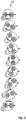
- Figures 6 and 7 show the paths of the centres of rotation of the machining heads 42A, 42B.
- the paths assume a substantially elliptical configuration, in which one of the ends is open, owing to the relative advancing movement of conveyor belt and machining head in the longitudinal direction and owing to the alternating movement of the beam in the transverse direction.
- Fig. 6 shows instead the paths of the two heads for a single cycle, namely a forwards and backwards stroke of the spindle-carrying beam 24, while Figure 7 shows the same relative longitudinal translation movement of machining heads and bench, which has not been amplified, but represents the real situation, in the case of a plurality of cycles, namely with a continuous movement.
- the machine according to the present invention may comprise means for detecting the dimensions of the slab resting on the bench 16. By means of detection of the dimensions, the control unit may directly set both the limit values for the transverse movement of the beam and optionally the speed of relative advancing movement of slab and machining heads.
- control unit is designed to set automatic limit values so as to condition reciprocally the movement of the beam, the rotation of the spindle-carrying support and the rotation of the machining heads.
- the slab is seen as not having a varied polishing effect or machining marks, even when viewed against the light, and this therefore gives its a very special quality.
- pneumatic actuators for the vertical movement of the spindles advantageously allows the machining pressure to be more easily adjusted and maintained.
- oil-hydraulic cylinders may be provided instead of pneumatic cylinders for movement of the spindles.
Landscapes
- Engineering & Computer Science (AREA)
- Mechanical Engineering (AREA)
- Chemical & Material Sciences (AREA)
- Ceramic Engineering (AREA)
- Inorganic Chemistry (AREA)
- Constituent Portions Of Griding Lathes, Driving, Sensing And Control (AREA)
- Finish Polishing, Edge Sharpening, And Grinding By Specific Grinding Devices (AREA)
Claims (12)
- Procédé de lissage et/ou de polissage de plaques de pierre ou de matériau en forme de pierre avec une machine comprenant :un banc de support (16) destiné à une plaque à usiner placée sur une courroie transporteuse ;au moins un poste d'usinage (14) comprenant deux structures d'appui (20, 22), disposé transversalement en travers du banc de support (16), une traverse porte-broche (24), adapté pour être déplacé par-dessus les structures d'appui dans une direction transversale, et prévu sur lesdites structures d'appui (20, 22) ;au moins une structure porte-broche (34), adaptée pour être tournée autour de son propre axe vertical (32), et prévue sur la traverse porte-broche (24) ;chaque structure porte-broche (34) étant munie de deux broches motorisées (38A ; 38B), dont les extrémités sont munies de têtes d'usinage (42A, 42B) espacées et opposées l'une à l'autre par rapport à l'axe vertical (32) de la structure porte-broche (34) et comprenant des outils d'usinage (44A, 44B) ;une unité informatisée programmable destinée à contrôler la position, le mouvement et la vitesse des éléments mobiles,ledit procédé étant caractérisé en ce que :- la traverse et les structures porte-broches se déplacent de manière coordonnée et synchronisée les unes par rapport aux autres ;- pour chaque course de la traverse (24) dans la direction transversale, chaque structure porte-broche (34) effectue une rotation à 180° autour de son axe de rotation ;- lorsque la traverse (24) est située au niveau de la ligne centrale du banc (16), l'axe (60) qui relie les axes de rotation des broches (38A, 38B) est perpendiculaire à la direction longitudinale de la machine ; et- lorsque la traverse (24) est située à la distance maximale par rapport à la ligne centrale du banc (16), l'axe (60) est parallèle à l'axe longitudinal de la machine.
- Procédé selon la revendication précédente, caractérisé en ce que les outils d'usinage (44A, 44B) sont déplacés selon la combinaison :- d'un mouvement de rotation de l'outil autour de l'axe de rotation vertical (40A, 40B) de la broche (38A, 38B) sur lequel la tête d'usinage (42A, 42B) est montée ;- d'un mouvement de pivotement autour de l'axe de rotation vertical (32) de la structure porte-broche (34) ;- d'un mouvement de translation alterné dans la direction transversale de la traverse porte-broche (24) ;- d'un mouvement de translation longitudinal du au mouvement d'avancée du matériau placé sur le banc (16) ; et- du mouvement transmis à l'outil (44A, 44B) par la tête d'usinage (42A, 42B).
- Procédé selon l'une quelconque des revendications précédentes, caractérisé en ce qu'il comprend une étape au cours de laquelle un moyen de détection détecte les dimensions de la plaque placée sur le banc et, à l'aide d'une unité de commande, les limites du mouvement de la traverse dans la direction transversale sont automatiquement définies.
- Procédé selon l'une quelconque des revendications précédentes, caractérisé en ce que, dans la position dans laquelle le mouvement transversal de la traverse (24) est inversé, les outils de la tête d'usinage dépassent partiellement du bord de la plaque.
- Procédé selon l'une quelconque des revendications précédentes, caractérisé en ce que les outils à patins (ou segments) oscillants sont montés sur la tête d'usinage (42A, 42B).
- Procédé selon l'une quelconque des revendications précédentes, caractérisé en ce que des outils sous la forme de meuleuses à plat sont montés sur la tête d'usinage (42A, 42B).
- Procédé selon l'une quelconque des revendications précédentes, caractérisé en ce que des outils sous la forme de rouleaux sont montés sur la tête d'usinage (42A, 42B).
- Procédé selon l'une quelconque des revendications précédentes, caractérisé en ce que la tête d'usinage (42A, 42B) est composée d'une plaque porte-abrasif sur laquelle des outils munis d'une surface d'appui plane sont appliqués.
- Procédé selon l'une quelconque des revendications précédentes, caractérisé en ce que la vitesse de rotation des structures porte-broches (34) est comprise entre 5 et 60 tours par minute.
- Procédé selon l'une quelconque des revendications précédentes, caractérisé en ce que la vitesse de rotation des broches est comprise entre 200 et 600 tours par minute.
- Procédé selon l'une quelconque des revendications précédentes, caractérisé en ce que la vitesse de translation relative du banc et du poste d'usinage (14) dans la direction longitudinale est comprise entre 0,2 et 5 mètres/minute.
- Procédé selon l'une quelconque des revendications précédentes, caractérisé en ce que la traverse effectue un nombre de cycles de mouvement dans la direction transversale compris entre 5 et 40 cycles par minute.
Applications Claiming Priority (2)
| Application Number | Priority Date | Filing Date | Title |
|---|---|---|---|
| ITTV20140111 | 2014-07-24 | ||
| PCT/IB2015/055536 WO2016012950A1 (fr) | 2014-07-24 | 2015-07-22 | Procédé de lissage et/ou polissage de dalles de pierre ou de matériau similaire à de la pierre |
Publications (2)
| Publication Number | Publication Date |
|---|---|
| EP3172013A1 EP3172013A1 (fr) | 2017-05-31 |
| EP3172013B1 true EP3172013B1 (fr) | 2018-03-28 |
Family
ID=51655935
Family Applications (1)
| Application Number | Title | Priority Date | Filing Date |
|---|---|---|---|
| EP15762724.1A Active EP3172013B1 (fr) | 2014-07-24 | 2015-07-22 | Procédé de lissage et/ou polissage de dalles de pierre ou de matériau similaire à de la pierre |
Country Status (9)
| Country | Link |
|---|---|
| US (1) | US10239179B2 (fr) |
| EP (1) | EP3172013B1 (fr) |
| KR (1) | KR102338662B1 (fr) |
| CN (1) | CN106660187B (fr) |
| CA (1) | CA2955856C (fr) |
| ES (1) | ES2669347T3 (fr) |
| IL (1) | IL249930B (fr) |
| PT (1) | PT3172013T (fr) |
| WO (1) | WO2016012950A1 (fr) |
Families Citing this family (9)
| Publication number | Priority date | Publication date | Assignee | Title |
|---|---|---|---|---|
| IT201600108003A1 (it) * | 2016-10-26 | 2018-04-26 | Piccolo Rosario Lo | Macchina levigatrice-lucidatrice per prodotti lastriformi in materiale lapideo |
| IT201600130117A1 (it) * | 2016-12-22 | 2018-06-22 | Breton Spa | Macchina e metodo per la levigatura e/o lucidatura di lastre di materiale lapideo, quale pietra naturale o agglomerata, ceramico e vetro |
| CN108284377B (zh) * | 2017-01-09 | 2023-12-19 | 广东科达洁能股份有限公司 | 一种瓷砖复合运动轨迹抛光方法 |
| CN109955146A (zh) * | 2018-05-14 | 2019-07-02 | 东莞市纳智自动化机械有限公司 | 一种压力可调充分冷却陶瓷材料批量打磨头 |
| CN108544313A (zh) * | 2018-06-20 | 2018-09-18 | 珠海桑贝思精密科技有限公司 | 平面打磨机 |
| CN115946016A (zh) * | 2022-06-21 | 2023-04-11 | 浙江谋皮环保科技有限公司 | 板带表面氧化皮处理总成 |
| CN116551546B (zh) * | 2023-05-11 | 2023-11-07 | 江苏巴马型钢有限公司 | 一种异型钢折角抛光设备及其使用方法 |
| CN117325018B (zh) * | 2023-09-21 | 2026-01-09 | 科达制造股份有限公司 | 一种板材抛磨装置及板材抛磨方法 |
| CN117182769A (zh) * | 2023-10-25 | 2023-12-08 | 浙江天马轴承集团有限公司 | 一种横梁结构及龙门式磨床 |
Family Cites Families (22)
| Publication number | Priority date | Publication date | Assignee | Title |
|---|---|---|---|---|
| US2735238A (en) * | 1956-02-21 | heffley | ||
| JPS5493288A (en) * | 1977-12-31 | 1979-07-24 | Bando Kiko Co | Glass chamfering machine |
| IT1218824B (it) * | 1987-09-15 | 1990-04-19 | Marcello Toncelli | Procedimento automatico per la levigatura e la lucidatura di lastre di marmo, granito o pietre in genere |
| US5056272A (en) * | 1990-07-16 | 1991-10-15 | Battaglia Gino C | Method and apparatus for reducing thickness of stone slabs |
| IT1292718B1 (it) * | 1997-04-24 | 1999-02-11 | R P Srl | Macchina levigatrice |
| US6152809A (en) * | 1998-09-03 | 2000-11-28 | Yenawine; Peter W. | Method and apparatus for cold-end processing full-lead crystal |
| IT1315616B1 (it) | 2000-03-15 | 2003-03-14 | Luigi Pedrini | Levigatrice per materiali lapidei, dotata di teste multiple allineatesu due travi oscillanti e parallele, nonche' con distanza regolabile. |
| SE518356C2 (sv) * | 2001-02-06 | 2002-10-01 | Haakan Thysell | Anordning vid mobil maskin för slipning av golvytor |
| ITVI20020080A1 (it) * | 2002-05-02 | 2003-11-03 | Costa Levigatrici Spa | Macchina levigatrice |
| DK200301826A (da) * | 2003-12-10 | 2005-06-11 | Flex Trim As | Slibeapparat til behandling af en flade |
| RU2268132C1 (ru) * | 2004-07-30 | 2006-01-20 | Общество с ограниченной ответственностью "Торговый Дом "КВАРЦ" | Полипланетарная машина для шлифовки, лощения и полировки полов |
| ITMO20050254A1 (it) * | 2005-10-06 | 2007-04-07 | Scm Group Spa | Gruppo abrasivo |
| US7351130B1 (en) * | 2006-11-14 | 2008-04-01 | Wen Chi Chang | Sanding machine having adjustable brush |
| DE102007031656A1 (de) * | 2007-07-06 | 2009-01-08 | Heesemann, Jürgen, Dipl.-Ing. | Schleifmaschine |
| CN100479993C (zh) * | 2007-11-29 | 2009-04-22 | 佛山市科利得机械有限公司 | 一种高效抛光机 |
| CN201109058Y (zh) * | 2007-11-29 | 2008-09-03 | 佛山市科利得机械有限公司 | 一种高效抛光机 |
| US20090163124A1 (en) * | 2007-12-19 | 2009-06-25 | Wen-Chi Chang | Reciprocating linear sander |
| CN101327568A (zh) * | 2008-07-19 | 2008-12-24 | 佛山市科利得机械有限公司 | 一种高效稳定的抛光磨削装置 |
| CN201324979Y (zh) * | 2008-11-10 | 2009-10-14 | 广东科达机电股份有限公司 | 瓷质薄板砖定厚粗抛机 |
| EP2255924A1 (fr) * | 2009-05-29 | 2010-12-01 | Mbd S.R.L. | Procédé d'étalonnage de surfaces de matériau de pierre |
| IT1396807B1 (it) * | 2009-11-25 | 2012-12-14 | Toncelli | Macchina di levigatura o lucidatura di lastre di materiale lapideo, quale pietra naturale e agglomerata, ceramico e vetro. |
| CN203622122U (zh) * | 2013-12-03 | 2014-06-04 | 昆山圣进威精密机械有限公司 | 石材研磨机 |
-
2015
- 2015-07-22 EP EP15762724.1A patent/EP3172013B1/fr active Active
- 2015-07-22 ES ES15762724.1T patent/ES2669347T3/es active Active
- 2015-07-22 KR KR1020177002652A patent/KR102338662B1/ko not_active Expired - Fee Related
- 2015-07-22 PT PT157627241T patent/PT3172013T/pt unknown
- 2015-07-22 CN CN201580039487.7A patent/CN106660187B/zh not_active Expired - Fee Related
- 2015-07-22 CA CA2955856A patent/CA2955856C/fr active Active
- 2015-07-22 US US15/328,168 patent/US10239179B2/en active Active
- 2015-07-22 WO PCT/IB2015/055536 patent/WO2016012950A1/fr not_active Ceased
-
2017
- 2017-01-04 IL IL249930A patent/IL249930B/en active IP Right Grant
Also Published As
| Publication number | Publication date |
|---|---|
| IL249930A0 (en) | 2017-03-30 |
| CA2955856A1 (fr) | 2016-01-28 |
| IL249930B (en) | 2020-11-30 |
| ES2669347T3 (es) | 2018-05-25 |
| US20170216988A1 (en) | 2017-08-03 |
| CN106660187A (zh) | 2017-05-10 |
| PT3172013T (pt) | 2018-05-25 |
| KR20170035925A (ko) | 2017-03-31 |
| EP3172013A1 (fr) | 2017-05-31 |
| WO2016012950A1 (fr) | 2016-01-28 |
| CN106660187B (zh) | 2019-07-02 |
| CA2955856C (fr) | 2022-05-31 |
| US10239179B2 (en) | 2019-03-26 |
| KR102338662B1 (ko) | 2021-12-14 |
Similar Documents
| Publication | Publication Date | Title |
|---|---|---|
| EP3172013B1 (fr) | Procédé de lissage et/ou polissage de dalles de pierre ou de matériau similaire à de la pierre | |
| US9238291B2 (en) | Machine for smoothing or polishing slabs of stone materials, such as natural and aggolomerated stone, ceramic and glass | |
| US11648636B2 (en) | Machine and method for grinding and/or polishing slabs of stone material, such as natural or agglomerated stone, ceramic and glass | |
| CN105813806A (zh) | 磨平和/或抛光如天然石和合成石的石材、陶瓷和玻璃的板坯的机器 | |
| WO2017134616A1 (fr) | Machine de polissage orbitale pour polir des dalles de pierre | |
| EP3628442B1 (fr) | Unité d'agrégat multi-outils pour polir des plaques de matériau en pierre ou de matériau synthétique et machine de polissage fournie avec cette unité | |
| US9011208B2 (en) | Dual-spindle grinder | |
| FI76945B (fi) | Foerfarande och anordning foer att finslipa ytor. | |
| US20200206976A1 (en) | Combined cutting and bevelling machine for slabs of stone or stone-like material | |
| TW202300277A (zh) | 平面磨床邊緣去毛刺倒圓裝置 | |
| EP3581331B1 (fr) | Ensemble de disques de meulage des bords de plaques de verre | |
| EP2501519A1 (fr) | Procédé de polissage-parachèvement de surfaces de matériaux pierreux et machine associée audit procédé | |
| JP5329877B2 (ja) | 被研削材の複合研削方法 | |
| RU2301745C2 (ru) | Способ получения рельефной поверхности и устройство для его осуществления | |
| CA3047699C (fr) | Machine et procede de meulage et/ou de polissage de dalles de materiau de pierre, tel que de la pierre naturelle ou agglomeree, de la ceramique et du verre | |
| EP3411182B1 (fr) | Machine de polissage orbitale pour polir des dalles de pierre | |
| ITVR940025A1 (it) | Macchina per compiere lavorazioni sui bordi di lastre di marmo, granito od altre pietre. |
Legal Events
| Date | Code | Title | Description |
|---|---|---|---|
| STAA | Information on the status of an ep patent application or granted ep patent |
Free format text: STATUS: THE INTERNATIONAL PUBLICATION HAS BEEN MADE |
|
| PUAI | Public reference made under article 153(3) epc to a published international application that has entered the european phase |
Free format text: ORIGINAL CODE: 0009012 |
|
| STAA | Information on the status of an ep patent application or granted ep patent |
Free format text: STATUS: REQUEST FOR EXAMINATION WAS MADE |
|
| 17P | Request for examination filed |
Effective date: 20170215 |
|
| AK | Designated contracting states |
Kind code of ref document: A1 Designated state(s): AL AT BE BG CH CY CZ DE DK EE ES FI FR GB GR HR HU IE IS IT LI LT LU LV MC MK MT NL NO PL PT RO RS SE SI SK SM TR |
|
| AX | Request for extension of the european patent |
Extension state: BA ME |
|
| DAV | Request for validation of the european patent (deleted) | ||
| DAX | Request for extension of the european patent (deleted) | ||
| GRAP | Despatch of communication of intention to grant a patent |
Free format text: ORIGINAL CODE: EPIDOSNIGR1 |
|
| STAA | Information on the status of an ep patent application or granted ep patent |
Free format text: STATUS: GRANT OF PATENT IS INTENDED |
|
| INTG | Intention to grant announced |
Effective date: 20171116 |
|
| GRAS | Grant fee paid |
Free format text: ORIGINAL CODE: EPIDOSNIGR3 |
|
| GRAA | (expected) grant |
Free format text: ORIGINAL CODE: 0009210 |
|
| STAA | Information on the status of an ep patent application or granted ep patent |
Free format text: STATUS: THE PATENT HAS BEEN GRANTED |
|
| AK | Designated contracting states |
Kind code of ref document: B1 Designated state(s): AL AT BE BG CH CY CZ DE DK EE ES FI FR GB GR HR HU IE IS IT LI LT LU LV MC MK MT NL NO PL PT RO RS SE SI SK SM TR |
|
| REG | Reference to a national code |
Ref country code: GB Ref legal event code: FG4D |
|
| REG | Reference to a national code |
Ref country code: CH Ref legal event code: EP |
|
| REG | Reference to a national code |
Ref country code: AT Ref legal event code: REF Ref document number: 982973 Country of ref document: AT Kind code of ref document: T Effective date: 20180415 |
|
| REG | Reference to a national code |
Ref country code: IE Ref legal event code: FG4D |
|
| REG | Reference to a national code |
Ref country code: DE Ref legal event code: R096 Ref document number: 602015009392 Country of ref document: DE |
|
| REG | Reference to a national code |
Ref country code: ES Ref legal event code: FG2A Ref document number: 2669347 Country of ref document: ES Kind code of ref document: T3 Effective date: 20180525 Ref country code: PT Ref legal event code: SC4A Ref document number: 3172013 Country of ref document: PT Date of ref document: 20180525 Kind code of ref document: T Free format text: AVAILABILITY OF NATIONAL TRANSLATION Effective date: 20180521 |
|
| PG25 | Lapsed in a contracting state [announced via postgrant information from national office to epo] |
Ref country code: LT Free format text: LAPSE BECAUSE OF FAILURE TO SUBMIT A TRANSLATION OF THE DESCRIPTION OR TO PAY THE FEE WITHIN THE PRESCRIBED TIME-LIMIT Effective date: 20180328 Ref country code: FI Free format text: LAPSE BECAUSE OF FAILURE TO SUBMIT A TRANSLATION OF THE DESCRIPTION OR TO PAY THE FEE WITHIN THE PRESCRIBED TIME-LIMIT Effective date: 20180328 Ref country code: NO Free format text: LAPSE BECAUSE OF FAILURE TO SUBMIT A TRANSLATION OF THE DESCRIPTION OR TO PAY THE FEE WITHIN THE PRESCRIBED TIME-LIMIT Effective date: 20180628 Ref country code: HR Free format text: LAPSE BECAUSE OF FAILURE TO SUBMIT A TRANSLATION OF THE DESCRIPTION OR TO PAY THE FEE WITHIN THE PRESCRIBED TIME-LIMIT Effective date: 20180328 |
|
| REG | Reference to a national code |
Ref country code: NL Ref legal event code: MP Effective date: 20180328 |
|
| REG | Reference to a national code |
Ref country code: LT Ref legal event code: MG4D |
|
| PG25 | Lapsed in a contracting state [announced via postgrant information from national office to epo] |
Ref country code: GR Free format text: LAPSE BECAUSE OF FAILURE TO SUBMIT A TRANSLATION OF THE DESCRIPTION OR TO PAY THE FEE WITHIN THE PRESCRIBED TIME-LIMIT Effective date: 20180629 Ref country code: BG Free format text: LAPSE BECAUSE OF FAILURE TO SUBMIT A TRANSLATION OF THE DESCRIPTION OR TO PAY THE FEE WITHIN THE PRESCRIBED TIME-LIMIT Effective date: 20180628 Ref country code: SE Free format text: LAPSE BECAUSE OF FAILURE TO SUBMIT A TRANSLATION OF THE DESCRIPTION OR TO PAY THE FEE WITHIN THE PRESCRIBED TIME-LIMIT Effective date: 20180328 Ref country code: LV Free format text: LAPSE BECAUSE OF FAILURE TO SUBMIT A TRANSLATION OF THE DESCRIPTION OR TO PAY THE FEE WITHIN THE PRESCRIBED TIME-LIMIT Effective date: 20180328 Ref country code: RS Free format text: LAPSE BECAUSE OF FAILURE TO SUBMIT A TRANSLATION OF THE DESCRIPTION OR TO PAY THE FEE WITHIN THE PRESCRIBED TIME-LIMIT Effective date: 20180328 |
|
| PG25 | Lapsed in a contracting state [announced via postgrant information from national office to epo] |
Ref country code: RO Free format text: LAPSE BECAUSE OF FAILURE TO SUBMIT A TRANSLATION OF THE DESCRIPTION OR TO PAY THE FEE WITHIN THE PRESCRIBED TIME-LIMIT Effective date: 20180328 Ref country code: AL Free format text: LAPSE BECAUSE OF FAILURE TO SUBMIT A TRANSLATION OF THE DESCRIPTION OR TO PAY THE FEE WITHIN THE PRESCRIBED TIME-LIMIT Effective date: 20180328 Ref country code: PL Free format text: LAPSE BECAUSE OF FAILURE TO SUBMIT A TRANSLATION OF THE DESCRIPTION OR TO PAY THE FEE WITHIN THE PRESCRIBED TIME-LIMIT Effective date: 20180328 Ref country code: NL Free format text: LAPSE BECAUSE OF FAILURE TO SUBMIT A TRANSLATION OF THE DESCRIPTION OR TO PAY THE FEE WITHIN THE PRESCRIBED TIME-LIMIT Effective date: 20180328 Ref country code: EE Free format text: LAPSE BECAUSE OF FAILURE TO SUBMIT A TRANSLATION OF THE DESCRIPTION OR TO PAY THE FEE WITHIN THE PRESCRIBED TIME-LIMIT Effective date: 20180328 |
|
| PG25 | Lapsed in a contracting state [announced via postgrant information from national office to epo] |
Ref country code: SM Free format text: LAPSE BECAUSE OF FAILURE TO SUBMIT A TRANSLATION OF THE DESCRIPTION OR TO PAY THE FEE WITHIN THE PRESCRIBED TIME-LIMIT Effective date: 20180328 Ref country code: SK Free format text: LAPSE BECAUSE OF FAILURE TO SUBMIT A TRANSLATION OF THE DESCRIPTION OR TO PAY THE FEE WITHIN THE PRESCRIBED TIME-LIMIT Effective date: 20180328 |
|
| REG | Reference to a national code |
Ref country code: AT Ref legal event code: MK05 Ref document number: 982973 Country of ref document: AT Kind code of ref document: T Effective date: 20180328 |
|
| REG | Reference to a national code |
Ref country code: DE Ref legal event code: R097 Ref document number: 602015009392 Country of ref document: DE |
|
| PG25 | Lapsed in a contracting state [announced via postgrant information from national office to epo] |
Ref country code: DK Free format text: LAPSE BECAUSE OF FAILURE TO SUBMIT A TRANSLATION OF THE DESCRIPTION OR TO PAY THE FEE WITHIN THE PRESCRIBED TIME-LIMIT Effective date: 20180328 Ref country code: AT Free format text: LAPSE BECAUSE OF FAILURE TO SUBMIT A TRANSLATION OF THE DESCRIPTION OR TO PAY THE FEE WITHIN THE PRESCRIBED TIME-LIMIT Effective date: 20180328 |
|
| PLBE | No opposition filed within time limit |
Free format text: ORIGINAL CODE: 0009261 |
|
| STAA | Information on the status of an ep patent application or granted ep patent |
Free format text: STATUS: NO OPPOSITION FILED WITHIN TIME LIMIT |
|
| REG | Reference to a national code |
Ref country code: CH Ref legal event code: PL |
|
| 26N | No opposition filed |
Effective date: 20190103 |
|
| PG25 | Lapsed in a contracting state [announced via postgrant information from national office to epo] |
Ref country code: LU Free format text: LAPSE BECAUSE OF NON-PAYMENT OF DUE FEES Effective date: 20180722 Ref country code: MC Free format text: LAPSE BECAUSE OF FAILURE TO SUBMIT A TRANSLATION OF THE DESCRIPTION OR TO PAY THE FEE WITHIN THE PRESCRIBED TIME-LIMIT Effective date: 20180328 |
|
| REG | Reference to a national code |
Ref country code: BE Ref legal event code: MM Effective date: 20180731 |
|
| REG | Reference to a national code |
Ref country code: IE Ref legal event code: MM4A |
|
| PG25 | Lapsed in a contracting state [announced via postgrant information from national office to epo] |
Ref country code: CH Free format text: LAPSE BECAUSE OF NON-PAYMENT OF DUE FEES Effective date: 20180731 Ref country code: LI Free format text: LAPSE BECAUSE OF NON-PAYMENT OF DUE FEES Effective date: 20180731 Ref country code: IE Free format text: LAPSE BECAUSE OF NON-PAYMENT OF DUE FEES Effective date: 20180722 Ref country code: FR Free format text: LAPSE BECAUSE OF NON-PAYMENT OF DUE FEES Effective date: 20180731 |
|
| PG25 | Lapsed in a contracting state [announced via postgrant information from national office to epo] |
Ref country code: BE Free format text: LAPSE BECAUSE OF NON-PAYMENT OF DUE FEES Effective date: 20180731 Ref country code: SI Free format text: LAPSE BECAUSE OF FAILURE TO SUBMIT A TRANSLATION OF THE DESCRIPTION OR TO PAY THE FEE WITHIN THE PRESCRIBED TIME-LIMIT Effective date: 20180328 |
|
| PG25 | Lapsed in a contracting state [announced via postgrant information from national office to epo] |
Ref country code: MT Free format text: LAPSE BECAUSE OF NON-PAYMENT OF DUE FEES Effective date: 20180722 |
|
| GBPC | Gb: european patent ceased through non-payment of renewal fee |
Effective date: 20190722 |
|
| PG25 | Lapsed in a contracting state [announced via postgrant information from national office to epo] |
Ref country code: TR Free format text: LAPSE BECAUSE OF FAILURE TO SUBMIT A TRANSLATION OF THE DESCRIPTION OR TO PAY THE FEE WITHIN THE PRESCRIBED TIME-LIMIT Effective date: 20180328 |
|
| PG25 | Lapsed in a contracting state [announced via postgrant information from national office to epo] |
Ref country code: GB Free format text: LAPSE BECAUSE OF NON-PAYMENT OF DUE FEES Effective date: 20190722 |
|
| PG25 | Lapsed in a contracting state [announced via postgrant information from national office to epo] |
Ref country code: HU Free format text: LAPSE BECAUSE OF FAILURE TO SUBMIT A TRANSLATION OF THE DESCRIPTION OR TO PAY THE FEE WITHIN THE PRESCRIBED TIME-LIMIT; INVALID AB INITIO Effective date: 20150722 Ref country code: CY Free format text: LAPSE BECAUSE OF FAILURE TO SUBMIT A TRANSLATION OF THE DESCRIPTION OR TO PAY THE FEE WITHIN THE PRESCRIBED TIME-LIMIT Effective date: 20180328 Ref country code: MK Free format text: LAPSE BECAUSE OF NON-PAYMENT OF DUE FEES Effective date: 20180328 |
|
| PG25 | Lapsed in a contracting state [announced via postgrant information from national office to epo] |
Ref country code: IS Free format text: LAPSE BECAUSE OF FAILURE TO SUBMIT A TRANSLATION OF THE DESCRIPTION OR TO PAY THE FEE WITHIN THE PRESCRIBED TIME-LIMIT Effective date: 20180728 |
|
| P01 | Opt-out of the competence of the unified patent court (upc) registered |
Effective date: 20230624 |
|
| PGFP | Annual fee paid to national office [announced via postgrant information from national office to epo] |
Ref country code: CZ Payment date: 20240625 Year of fee payment: 10 |
|
| PGFP | Annual fee paid to national office [announced via postgrant information from national office to epo] |
Ref country code: PT Payment date: 20240621 Year of fee payment: 10 |
|
| PGFP | Annual fee paid to national office [announced via postgrant information from national office to epo] |
Ref country code: DE Payment date: 20240619 Year of fee payment: 10 |
|
| PGFP | Annual fee paid to national office [announced via postgrant information from national office to epo] |
Ref country code: ES Payment date: 20240802 Year of fee payment: 10 |
|
| PGFP | Annual fee paid to national office [announced via postgrant information from national office to epo] |
Ref country code: IT Payment date: 20250619 Year of fee payment: 11 |
|
| REG | Reference to a national code |
Ref country code: DE Ref legal event code: R119 Ref document number: 602015009392 Country of ref document: DE |
|
| PG25 | Lapsed in a contracting state [announced via postgrant information from national office to epo] |
Ref country code: DE Free format text: LAPSE BECAUSE OF NON-PAYMENT OF DUE FEES Effective date: 20260203 |
|
| PG25 | Lapsed in a contracting state [announced via postgrant information from national office to epo] |
Ref country code: PT Free format text: LAPSE BECAUSE OF NON-PAYMENT OF DUE FEES Effective date: 20260122 Ref country code: CZ Free format text: LAPSE BECAUSE OF NON-PAYMENT OF DUE FEES Effective date: 20250722 |