EP3172091B1 - Fahrzeug mit einer fussgängerschutzvorrichtung - Google Patents
Fahrzeug mit einer fussgängerschutzvorrichtung Download PDFInfo
- Publication number
- EP3172091B1 EP3172091B1 EP15736786.3A EP15736786A EP3172091B1 EP 3172091 B1 EP3172091 B1 EP 3172091B1 EP 15736786 A EP15736786 A EP 15736786A EP 3172091 B1 EP3172091 B1 EP 3172091B1
- Authority
- EP
- European Patent Office
- Prior art keywords
- vehicle
- airbag
- hood
- engine cover
- region
- Prior art date
- Legal status (The legal status is an assumption and is not a legal conclusion. Google has not performed a legal analysis and makes no representation as to the accuracy of the status listed.)
- Active
Links
Images



Classifications
-
- B—PERFORMING OPERATIONS; TRANSPORTING
- B60—VEHICLES IN GENERAL
- B60R—VEHICLES, VEHICLE FITTINGS, OR VEHICLE PARTS, NOT OTHERWISE PROVIDED FOR
- B60R21/00—Arrangements or fittings on vehicles for protecting or preventing injuries to occupants or pedestrians in case of accidents or other traffic risks
- B60R21/34—Protecting non-occupants of a vehicle, e.g. pedestrians
- B60R21/36—Protecting non-occupants of a vehicle, e.g. pedestrians using airbags
-
- B—PERFORMING OPERATIONS; TRANSPORTING
- B60—VEHICLES IN GENERAL
- B60R—VEHICLES, VEHICLE FITTINGS, OR VEHICLE PARTS, NOT OTHERWISE PROVIDED FOR
- B60R21/00—Arrangements or fittings on vehicles for protecting or preventing injuries to occupants or pedestrians in case of accidents or other traffic risks
- B60R21/34—Protecting non-occupants of a vehicle, e.g. pedestrians
- B60R21/38—Protecting non-occupants of a vehicle, e.g. pedestrians using means for lifting bonnets
Definitions
- the invention relates to a vehicle with a pedestrian protection device which comprises an engine hood which can be erected on an edge which faces a windscreen at an impact detected by a person on the vehicle.
- pedestrian protection devices for vehicles comprising an actively deployable hood and / or a deployable airbag are known.
- the hood In a detected impact of a person to the vehicle, the hood is at least in an area facing a windshield set up, the airbag to protect the person from an impact, the windshield this substantially covers.
- the JP2006076448 discloses a vehicle having a pedestrian protection device according to the preamble of claim 1.
- the invention has for its object to provide a comparison with the prior art improved vehicle with a pedestrian protection device.
- a vehicle has a pedestrian protection device, which comprises an engine hood which can be erected on an edge facing a windshield at a detected impact of a person on the vehicle.
- a pedestrian protection device which comprises an engine hood which can be erected on an edge facing a windshield at a detected impact of a person on the vehicle.
- at least one airbag is additionally provided, which extends in the tripped state over a region of an A-pillar and an area of the windshield adjacent thereto.
- the at least one airbag is a protective area of the pedestrian protection device to the area of the A-pillar and a lens root extended.
- a field of vision of a driver of the vehicle is limited by means of such an airbag little to no permanent.
- FIG. 1 is a perspective view of a front portion of a vehicle 1 with two triggered airbags 2 shown as additional components of a pedestrian protection device.
- the pedestrian protection device also comprises a hood 3, which is displaceable in the event of a detected impact of a person to the vehicle 1 in the direction of a windshield 4 and on a side facing the windshield 4 edge 3.1 can be raised.
- the two airbags 2 extend over an area of a respective one in FIG. 2 shown A-pillar 5 of the vehicle 1 and have a substantially cylindrical shape. Both airbags 2 and an associated actuator are arranged in a fabric tube 6. As an alternative to the cylindrical shape, the airbags 2 also different shapes, such as. B. an oval shape.
- An end 6.1 of the respective fabric tube 6 is attached to the edge 3.1 of the hood 3 and another end 6.2 is mounted in the region of a front roof cross member of a vehicle roof 7. It is also conceivable that one end 6.1 is arranged in the region of a hinge of the engine hood 3. The additional end 6.2 may alternatively or additionally be arranged and fastened in the region of the A pillar 5.
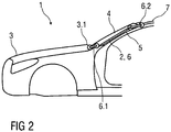
- FIG. 2 shows a side view of the front portion of the vehicle 1, wherein the airbags 2 are shown in the untreated state.
- the two airbags 2 are triggered and the hood 3 is unlocked for setting up and sectionwise moving.
- FIGS. 3 to 5 each show a movement phase when setting up the hood 3 in operative connection with the two airbags. 2
- An impact of a person on the vehicle 1 has been detected, wherein the impact exceeds a predetermined threshold, so that the airbags 2 and the hood 3 are controlled.
- the airbags 2 are acted upon by a gas, so that they unfold and increase their volume, whereby the fabric tube 6 of the respective airbag 2 is shortened.
- the respective fabric hose 6 is attached to the edge 3.1 of the hood 3, so that acts by shortening the fabric tube 6, a tensile force at least to support an erection of the hood 3 on this.
- the respective fabric hose 6 may alternatively be fastened in the region of a hinge of the engine hood 3.
- FIG. 4 has the fabric hose 6 compared to a in FIG. 3 shown first movement phase shortened even further, whereby the hood 3 is set up further.
- FIG. 5 shows a further movement phase of the hood 3 and also the airbags 2, wherein the hood 3 by means of the volume increase of the airbags 2 shortening fabric tubes 6 in the direction of the windshield 4 is displaceable, so that a so-called wiper shaft or cowl of the vehicle 1 as injury protection at least partially covered by the hood 3.
- Both the airbags 2 and the hood 3 have their operative position at least to reduce a risk of injury to the person bouncing on the vehicle 1.
- FIGS. 6 to 8 each show a movement phase when resetting the hood 3 in its starting position.
- the two airbags 2 have a predetermined service life, so that a pressure in the interior of the airbags 2 continuously decreases after the end of the service life. This reduces the volume of the airbags 2, so that the fabric tubes 6 extend and the hood 3 is positioned in its initial position, which in FIG. 8 is shown.
- FIG. 9 shows the hood 3 in the erected state, wherein in addition to the airbags 2, a not-shown spring element in the form of a torsion spring and an airbag element are provided as a damping element 8.
- the torsion bar spring rotates so that it can be prestressed when setting up the hood 3.
- the fabric hoses 6 are lengthened, so that no more pulling force acts on the engine hood 3.
- the torsion spring relaxes, and the hood 3 is positioned in the direction of its initial position due to the acting spring force.
- the damping element 8 When setting up the hood 3 in the active position, the damping element 8, which is arranged in the region of the edge 3.1 of the hood 3, automatically filled. By means of the damping element 8 is a damping of the raised hood 3 in an impact on the same adjustable.
- damping element in the region of the edge 3.1 of the hood 3 may be arranged.
Landscapes
- Engineering & Computer Science (AREA)
- Mechanical Engineering (AREA)
- Superstructure Of Vehicle (AREA)
- Air Bags (AREA)
- Body Structure For Vehicles (AREA)
Description
- Die Erfindung betrifft ein Fahrzeug mit einer Fußgängerschutzvorrichtung, welche eine bei einem erfassten Anprall einer Person an das Fahrzeug zumindest an einer einer Windschutzscheibe zugewandten Kante aufstellbare Motorhaube umfasst.
- Im Allgemeinen sind Fußgängerschutzvorrichtungen für Fahrzeuge, die eine aktiv aufstellbare Motorhaube und/oder einen auslösbaren Airbag umfassen, bekannt. Bei einem erfassten Anprall einer Person an das Fahrzeug ist die Motorhaube zumindest in einem einer Windschutzscheibe zugewandten Bereich aufstellbar, wobei der Airbag zum Schutz der Person vor einem Aufprall die Windschutzscheibe diese im Wesentlichen abdeckt. Die
JP2006076448 - Der Erfindung liegt die Aufgabe zugrunde, ein gegenüber dem Stand der Technik verbessertes Fahrzeug mit einer Fußgängerschutzvorrichtung anzugeben.
- Die Aufgabe wird erfindungsgemäß durch die in Anspruch 1 angegebenen Merkmale gelöst.
- Vorteilhafte Ausgestaltungen der Erfindung sind Gegenstand der Unteransprüche.
- Ein Fahrzeug weist eine Fußgängerschutzvorrichtung auf, welche eine bei einem erfassten Anprall einer Person an das Fahrzeug zumindest an einer einer Windschutzscheibe zugewandten Kante aufstellbare Motorhaube umfasst. Erfindungsgemäß ist zusätzlich zumindest ein Airbag vorgesehen, welcher sich im ausgelösten Zustand über einen Bereich einer A-Säule und einen an diese angrenzenden Bereich der Windschutzscheibe erstreckt.
- Mittels des zumindest einen Airbags wird ein Schutzbereich der Fußgängerschutzvorrichtung um den Bereich der A-Säule und einer Scheibenwurzel erweitert. Ein Sichtbereich eines Fahrers des Fahrzeuges wird mittels eines solchen Airbags wenig bis gar nicht dauerhaft eingeschränkt.
- Ausführungsbeispiele der Erfindung werden im Folgenden anhand von Zeichnungen näher erläutert.
- Dabei zeigen:
- Fig. 1
- schematisch eine perspektivische Ansicht eines Frontbereiches eines Fahrzeuges mit zwei ausgelösten Airbags,
- Fig. 2
- schematisch eine Seitenansicht des Frontbereiches mit den Airbags im unausgelösten Zustand,
- Fig. 3
- schematisch eine Seitenansicht des Frontbereiches mit teilweise aufgestellter Motorhaube und ausgelösten Airbags,
- Fig. 4
- schematisch eine weitere Seitenansicht des Frontbereiches mit teilweise aufgestellter Motorhaube und ausgelöstem Airbag,
- Fig. 5
- schematisch eine Seitenansicht des Frontbereiches mit aufgestellter Motorhaube und ausgelösten Airbags,
- Fig. 6
- schematisch eine Seitenansicht des Frontbereiches bei einem Rückstellen der Motorhaube in eine Ausgangsstellung,
- Fig. 7
- schematisch eine weitere Seitenansicht des Frontbereiches bei einem Rückstellen der Motohaube,
- Fig. 8
- schematisch eine Seitenansicht des Frontbereiches mit zurückgestellter Motorhaube und
- Fig. 9
- schematisch eines Seitenansicht des Frontbereiches mit aufgestellter Motorhaube in einer möglichen Ausführungsform.
- Einander entsprechende Teile sind in allen Figuren mit den gleichen Bezugszeichen versehen.
- In
Figur 1 ist eine perspektivische Ansicht eines Frontbereiches eines Fahrzeuges 1 mit zwei ausgelösten Airbags 2 als zusätzliche Komponenten einer Fußgängerschutzvorrichtung dargestellt. - Die Fußgängerschutzvorrichtung umfasst zudem eine Motorhaube 3, die bei einem erfassten Anprall einer Person an das Fahrzeug 1 in Richtung einer Windschutzscheibe 4 verschiebbar und an einer der Windschutzscheibe 4 zugewandten Kante 3.1 anhebbar ist.
- Die beiden Airbags 2 erstrecken sich über einen Bereich einer jeweiligen u. a. in
Figur 2 gezeigten A-Säule 5 des Fahrzeuges 1 und weisen im Wesentlichen eine zylindrische Form auf. Beide Airbags 2 und eine zugehörige Aktorik sind in einem Gewebeschlauch 6 angeordnet. Alternativ zu der zylindrischen Form können die Airbags 2 auch unterschiedliche Formen, wie z. B. eine ovale Form, aufweisen. - Ein Ende 6.1 des jeweiligen Gewebeschlauches 6 ist an der Kante 3.1 der Motorhaube 3 und ein weiteres Ende 6.2 ist im Bereich eines vorderen Dachquerträgers eines Fahrzeugdaches 7 befestigt. Denkbar ist auch, dass das eine Ende 6.1 im Bereich eines Scharniers der Motorhaube 3 angeordnet ist. Das weitere Ende 6.2 kann alternativ oder zusätzlich im Bereich der A-Säule 5 angeordnet und befestigt sein.
-
Figur 2 zeigt eine Seitenansicht des Frontbereiches des Fahrzeuges 1, wobei die Airbags 2 im unausgelösten Zustand dargestellt sind. - Im unausgelösten Zustand ist der jeweilige Airbag 2 nicht sichtbar unterhalb eines die A-Säule 5 verdeckenden, nicht näher dargestellten Zierelementes angeordnet.
- Bei einem Anprall einer Person an das Fahrzeug 1 sind die beiden Airbags 2 auslösbar und die Motorhaube 3 wird zum Aufstellen und abschnittsweisen Verschieben entriegelt.
- Die
Figuren 3 bis 5 zeigen jeweils eine Bewegungsphase beim Aufstellen der Motorhaube 3 im Wirkzusammenhang mit den beiden Airbags 2. - Ein Anprall einer Person an das Fahrzeug 1 wurde erfasst, wobei der Anprall einen vorgegebenen Schwellwert überschreitet, so dass die Airbags 2 und die Motorhaube 3 angesteuert werden.
- Die Airbags 2 werden mit einem Gas beaufschlagt, so dass sich diese entfalten und deren Volumen vergrößert, wodurch sich der Gewebeschlauch 6 des jeweiligen Airbags 2 verkürzt.
- Der jeweilige Gewebeschlauch 6 ist an der Kante 3.1 der Motorhaube 3 befestigt, so dass durch das Verkürzen des Gewebeschlauches 6 eine Zugkraft zumindest zur Unterstützung eines Aufstellens der Motorhaube 3 auf diese wirkt. Wie oben beschrieben, kann der jeweilige Gewebeschlauch 6 alternativ im Bereich eines Scharniers der Motorhaube 3 befestigt sein.
- In
Figur 4 hat sich der Gewebeschlauch 6 im Vergleich zu einer inFigur 3 gezeigten ersten Bewegungsphase noch weiter verkürzt, wodurch die Motorhaube 3 weiter aufstellbar ist. -
Figur 5 zeigt eine weitere Bewegungsphase der Motorhaube 3 und auch der Airbags 2, wobei die Motorhaube 3 mittels der sich durch die Volumenzunahme der Airbags 2 verkürzenden Gewebeschläuche 6 in Richtung der Windschutzscheibe 4 verschiebbar ist, so dass ein sogenannter Wischerschacht oder Windlauf des Fahrzeuges 1 als Verletzungsschutz zumindest teilweise mittels der Motorhaube 3 abgedeckt ist. - In dem vorliegenden Ausführungsbeispiel gemäß
Figur 5 weisen sowohl die Airbags 2 als auch die Motorhaube 3 ihre Wirkstellung zumindest zur Verringerung einer Verletzungsgefahr für die auf das Fahrzeug 1 prallende Person auf. - Die
Figuren 6 bis 8 zeigen jeweils eine Bewegungsphase bei einem Rückstellen der Motorhaube 3 in ihre Ausgangsstellung. - Die beiden Airbags 2 weisen eine vorgegebene Standzeit auf, so dass sich ein Druck im Inneren der Airbags 2 nach Ablauf der Standzeit kontinuierlich verringert. Dadurch verringert sich das Volumen der Airbags 2, so dass sich die Gewebeschläuche 6 verlängern und sich die Motorhaube 3 in ihre Ausgangstellung positioniert, welche in
Figur 8 dargestellt ist. - Beim Erreichen der Ausgangstellung ist das Gas weitestgehend aus den Airbags 2 entwichen, so dass der jeweilige Gewebeschlauch 6 seine Ausgangslänge aufweist, so dass keine Zugkraft mehr auf die Motorhaube 3 wirkt und diese ihre Ausgangsstellung einnimmt.
-
Figur 9 zeigt die Motorhaube 3 im aufgestellten Zustand, wobei zusätzlich zu den Airbags 2 ein nicht näher dargestelltes Federelement in Form einer.Drehstabfeder und ein Airbagelement als Dämpfungselement 8 vorgesehen sind. - Bei einer auf die Motorhaube 3 mittels der Airbags 2 wirkenden Zugkraft aufgrund der durch die Volumenzunahme bedingten Verkürzung der Gewebeschläuche 6 verdreht sich die Drehstabfeder, so dass diese beim Aufstellen der Motorhaube 3 vorspannbar ist.
- Verringert sich das Volumen der Airbags 2, verlängern sich die Gewebeschläuche 6, so dass auf die Motorhaube 3 keine Zugkraft mehr wirkt. Die Drehstabfeder entspannt sich, und die Motorhaube 3 positioniert sich aufgrund der wirkenden Federkraft in Richtung ihrer Ausgangsstellung.
- Bei einem Aufstellen der Motorhaube 3 in die Wirkstellung ist das Dämpfungselement 8, welches im Bereich der Kante 3.1 der Motorhaube 3 angeordnet ist, automatisch befüllbar. Mittels des Dämpfungselementes 8 ist eine Dämpfung der aufgestellten Motorhaube 3 bei einem Aufprall auf dieselbe einstellbar.
- Beispielsweise ist das Dämpfungselement 8 Bestandteil eines der Airbags 2 zum Aufstellen der Motorhaube 3. Dabei ist der Einsatz eines Dämpfungselementes 8 mit unterschiedlicher Zug- und Druckstufe denkbar.
- Alternativ oder zusätzlich kann auch ein anderes Dämpfungselement im Bereich der Kante 3.1 der Motorhaube 3 angeordnet sein.
Claims (5)
- Fahrzeug (1) mit einer Fußgängerschutzvorrichtung, umfassend eine bei einem erfassten Anprall einer Person an das Fahrzeug (1) zumindest an einer einer Windschutzscheibe (4) zugewandten Kante (3.1) aufstellbare und zusätzlich in Richtung der Windschutzscheibe (4) verschiebbaren Motorhaube (3), wobei zusätzlich zumindest ein Airbag (2) vorgesehen ist, welcher sich im ausgelösten Zustand über einen Bereich einer A-Säule und einen an diese angrenzenden Bereich der Windschutzscheibe (4) erstreckt, dadurch gekennzeichnet, dass. bei Anprall einer Person mittels des zumindest einen Airbags (2) eine Zugkraft auf die Motorhaube (3) zum Aufstellen derselben wirkt.
- Fahrzeug (1) nach Anspruch 1,
dadurch gekennzeichnet, dass der zumindest eine Airbag (2) zylinderförmig oder oval ausgebildet und in einem Gewebeschlauch (6) angeordnet ist und der Gewebeschlauch (6) mit einem Ende (6.1) an der Kante (3.1) der Motorhaube (3) oder im Bereich eines Scharniers der Motorhaube (3) und einem weiteren Ende (6.2) im Bereich eines Dachquerträgers des Fahrzeugdaches (7), einer Karosserie, der A-Säule (5) und/oder eines Dachrahmens befestigt ist. - Fahrzeug (1) nach Anspruch 1,
dadurch gekennzeichnet, dass der zumindest eine Airbag (2) in einem Gewebeschlauch (6) angeordnet und der Gewebeschlauch (6) einerseits an einer Kante (3.1) der Motorhaube (3) oder im Bereich eines Scharniers der Motorhaube (3) und andererseits im Bereich des vorderen Dachquerträgers eines Fahrzeugdaches (7) befestigt ist, so dass bei einer Entfaltung des zumindest einen Airbags (2) sich der Gewebeschlauch (6) verkürzt und eine Zugkraft auf die Motorhaube (3) wirkt. - Fahrzeug (1) nach Anspruch 1,
dadurch gekennzeichnet, dass der zumindest eine Airbag (2) in einem Gewebeschlauch (6) angeordnet ist und mittels des sich durch die Volumenzunahme des zumindest einen Airbags (2) verkürzenden Gewebeschlauches (6) die Motorhaube (3) in Richtung der Windschutzscheibe (4) verschiebbar ist. - Fahrzeug (1) nach Anspruch 1,
dadurch gekennzeichnet, dass der Airbag (2) im unausgelösten Zustand unterhalb eines die A-Säule (5) verdeckendes Zierelementes und/oder Abdeckelementes angeordnet ist.
Applications Claiming Priority (2)
| Application Number | Priority Date | Filing Date | Title |
|---|---|---|---|
| DE102014010872.4A DE102014010872A1 (de) | 2014-07-24 | 2014-07-24 | Fahrzeug mit einer Fußgängerschutzvorrichtung |
| PCT/EP2015/001380 WO2016012077A1 (de) | 2014-07-24 | 2015-07-07 | Fahrzeug mit einer fussgängerschutzvorrichtung |
Publications (2)
| Publication Number | Publication Date |
|---|---|
| EP3172091A1 EP3172091A1 (de) | 2017-05-31 |
| EP3172091B1 true EP3172091B1 (de) | 2018-12-26 |
Family
ID=53546198
Family Applications (1)
| Application Number | Title | Priority Date | Filing Date |
|---|---|---|---|
| EP15736786.3A Active EP3172091B1 (de) | 2014-07-24 | 2015-07-07 | Fahrzeug mit einer fussgängerschutzvorrichtung |
Country Status (6)
| Country | Link |
|---|---|
| US (1) | US9988011B2 (de) |
| EP (1) | EP3172091B1 (de) |
| JP (1) | JP6377243B2 (de) |
| CN (1) | CN106573594B (de) |
| DE (1) | DE102014010872A1 (de) |
| WO (1) | WO2016012077A1 (de) |
Families Citing this family (15)
| Publication number | Priority date | Publication date | Assignee | Title |
|---|---|---|---|---|
| WO2015103437A1 (en) * | 2013-12-31 | 2015-07-09 | Tk Holdings Inc. | Active pedestrian protection system |
| JP2017178211A (ja) * | 2016-03-31 | 2017-10-05 | 株式会社Subaru | 車両のサイクリスト保護装置 |
| DE102016012085A1 (de) | 2016-10-08 | 2017-09-14 | Daimler Ag | Insassenschutzvorrichtung und Fahrzeug |
| DE102016012084A1 (de) | 2016-10-08 | 2017-10-05 | Daimler Ag | Insassenschutzvorrichtung und Fahrzeug |
| DE102016012083A1 (de) | 2016-10-08 | 2017-10-05 | Daimler Ag | Insassenschutzvorrichtung und Fahrzeug |
| DE102016012106A1 (de) | 2016-10-08 | 2017-10-05 | Daimler Ag | Insassenschutzvorrichtung und Fahrzeug |
| DE102016012075A1 (de) | 2016-10-08 | 2017-09-14 | Daimler Ag | Insassenschutzvorrichtung und Fahrzeug |
| KR102596236B1 (ko) * | 2016-11-23 | 2023-11-01 | 현대자동차주식회사 | 차량용 액티브 후드장치 |
| DE102017201936A1 (de) * | 2017-02-08 | 2018-08-09 | Robert Bosch Gmbh | Verfahren zur Reduzierung eines Kollisionsschadens |
| CN106828401B (zh) * | 2017-03-24 | 2019-11-26 | 北京汽车股份有限公司 | 车辆 |
| DE102017008818A1 (de) | 2017-09-20 | 2019-03-21 | Daimler Ag | Gassackanordnung für ein Kraftfahrzeug |
| JP7011985B2 (ja) * | 2018-07-17 | 2022-02-10 | 本田技研工業株式会社 | 車体構造 |
| US11491950B2 (en) * | 2021-03-01 | 2022-11-08 | Ford Global Technologies, Llc | Vehicle external airbag |
| DE102023112737A1 (de) * | 2023-05-15 | 2024-11-21 | Bayerische Motoren Werke Aktiengesellschaft | Anordnung einer Fronthaube an einem Bauelement eines Kraftfahrzeugs sowie Verfahren |
| EP4603369A1 (de) * | 2024-02-15 | 2025-08-20 | Volvo Car Corporation | Frontsäulenanordnung für ein fahrzeug, schutzsystem, verfahren zum betreiben einer frontsäulenanordnung, verwendung und fahrzeug |
Citations (4)
| Publication number | Priority date | Publication date | Assignee | Title |
|---|---|---|---|---|
| DE10020660A1 (de) * | 2000-04-27 | 2001-10-31 | Volkswagen Ag | Fahrzeug, insbesondere Kraftfahrzeug |
| DE10332365A1 (de) * | 2003-07-17 | 2005-02-17 | Opel Eisenach Gmbh | Karosserie mit versenkbarem Karosserieelement |
| JP2008307956A (ja) * | 2007-06-12 | 2008-12-25 | Toyoda Gosei Co Ltd | フードロック機構 |
| DE102007034556A1 (de) * | 2007-07-25 | 2009-01-29 | Audi Ag | Verriegelungseinrichtung für die Frontklappe eines Kraftfahrzeuges |
Family Cites Families (19)
| Publication number | Priority date | Publication date | Assignee | Title |
|---|---|---|---|---|
| DE10013563A1 (de) * | 2000-03-21 | 2001-10-04 | Acts Gmbh & Co Kg | Sicherheitssystem |
| JP3711847B2 (ja) * | 2000-07-27 | 2005-11-02 | 日産自動車株式会社 | 車両用エアバッグ装置 |
| JP2002283939A (ja) * | 2001-03-29 | 2002-10-03 | Toyota Motor Corp | 歩行者保護エアバッグ装置 |
| US6415883B1 (en) * | 2002-01-24 | 2002-07-09 | Ford Global Technologies, Inc. | Deployable A-pillar covers for pedestrian protection |
| JP4160848B2 (ja) * | 2003-03-20 | 2008-10-08 | 本田技研工業株式会社 | 車両用衝突物保護装置 |
| DE102004029757A1 (de) * | 2004-06-19 | 2006-01-05 | Adam Opel Ag | Kraftfahrzeug mit aktivem Fußgängerschutz |
| JP2006076448A (ja) * | 2004-09-09 | 2006-03-23 | Nippon Plast Co Ltd | 歩行者等保護用エアバッグ装置 |
| JP4486463B2 (ja) * | 2004-09-30 | 2010-06-23 | 日本プラスト株式会社 | 非乗員保護装置 |
| US7232178B2 (en) * | 2005-02-10 | 2007-06-19 | General Motors Corporation | Vehicle hood assembly and method of elevating vehicle hood |
| FR2886612B1 (fr) * | 2005-06-06 | 2007-10-12 | Renault Sas | Dispositif de commande de l'ouverture du capot d'un vehicule, notamment pour proteger la tete d'un pieton en cas de choc. |
| JP2007191102A (ja) * | 2006-01-20 | 2007-08-02 | Mazda Motor Corp | 車両用歩行者保護装置 |
| JP4972024B2 (ja) * | 2008-03-27 | 2012-07-11 | タカタ株式会社 | エアバッグ装置 |
| US7997375B2 (en) * | 2009-04-17 | 2011-08-16 | Tony Shaw | Vehicle hood apparatus |
| CN101791973A (zh) * | 2009-11-20 | 2010-08-04 | 唐健 | 保护行人和车上人员的新型汽车引擎盖 |
| EP2733024B1 (de) * | 2012-11-15 | 2016-04-06 | Volvo Car Corporation | Sicherheitsanordnung für ein Fahrzeug |
| EP2743145B1 (de) * | 2012-12-12 | 2017-04-19 | Volvo Car Corporation | Sicherheitsanordnung für ein Kraftfahrzeug |
| US9834171B2 (en) * | 2013-05-08 | 2017-12-05 | GM Global Technology Operations LLC | Fender located pedestrian protection airbag |
| JP5983663B2 (ja) * | 2014-03-10 | 2016-09-06 | トヨタ自動車株式会社 | 歩行者保護エアバッグ装置 |
| KR101640550B1 (ko) * | 2014-09-26 | 2016-07-18 | 현대자동차주식회사 | 차량용 액티브 후드 장치 |
-
2014
- 2014-07-24 DE DE102014010872.4A patent/DE102014010872A1/de not_active Withdrawn
-
2015
- 2015-07-07 US US15/328,162 patent/US9988011B2/en active Active
- 2015-07-07 CN CN201580040233.7A patent/CN106573594B/zh active Active
- 2015-07-07 JP JP2017501405A patent/JP6377243B2/ja active Active
- 2015-07-07 EP EP15736786.3A patent/EP3172091B1/de active Active
- 2015-07-07 WO PCT/EP2015/001380 patent/WO2016012077A1/de not_active Ceased
Patent Citations (4)
| Publication number | Priority date | Publication date | Assignee | Title |
|---|---|---|---|---|
| DE10020660A1 (de) * | 2000-04-27 | 2001-10-31 | Volkswagen Ag | Fahrzeug, insbesondere Kraftfahrzeug |
| DE10332365A1 (de) * | 2003-07-17 | 2005-02-17 | Opel Eisenach Gmbh | Karosserie mit versenkbarem Karosserieelement |
| JP2008307956A (ja) * | 2007-06-12 | 2008-12-25 | Toyoda Gosei Co Ltd | フードロック機構 |
| DE102007034556A1 (de) * | 2007-07-25 | 2009-01-29 | Audi Ag | Verriegelungseinrichtung für die Frontklappe eines Kraftfahrzeuges |
Also Published As
| Publication number | Publication date |
|---|---|
| US9988011B2 (en) | 2018-06-05 |
| JP2017521315A (ja) | 2017-08-03 |
| DE102014010872A1 (de) | 2016-01-28 |
| JP6377243B2 (ja) | 2018-08-22 |
| WO2016012077A1 (de) | 2016-01-28 |
| CN106573594B (zh) | 2019-07-23 |
| EP3172091A1 (de) | 2017-05-31 |
| CN106573594A (zh) | 2017-04-19 |
| US20170217400A1 (en) | 2017-08-03 |
Similar Documents
| Publication | Publication Date | Title |
|---|---|---|
| EP3172091B1 (de) | Fahrzeug mit einer fussgängerschutzvorrichtung | |
| DE102007033796B4 (de) | Fahrzeug mit äußerem Aufprallschutz | |
| DE10066268B4 (de) | Sicherheitssystem für ein Kraftfahrzeug | |
| DE10323118B4 (de) | Einrichtung zum manuellen Reversieren einer Vorrichtung zum Schutz von Personen bei einem Frontalaufprall auf ein Kraftfahrzeug | |
| WO2019121222A1 (de) | Fahrzeuginsassenschutzsystem sowie verfahren zum betreiben eines fahrzeuginsassenschutzsystems | |
| DE102004062105B4 (de) | Vorrichtung zum Schutz von Personen bei einem Frontalaufprall auf ein Kraftfahrzeug durch aktives Aufstellen dessen Fronthaube | |
| WO2015169437A1 (de) | Modulabdeckung, anordnung einer modulabdeckung zwischen einem fahrzeugdach und einem fahrzeughimmel, gassackmodul und fahrzeugsicherheitssystem | |
| DE102014018877A1 (de) | Sicherheitsvorrichtung für ein Fahrzeug, Fahrzeug und Verfahren zum Betrieb der Sicherheitsvorrichtung | |
| WO2016083291A1 (de) | Aufpralldämpfende bauteilanordnung für ein kraftfahrzeug | |
| DE102011114297A1 (de) | Sicherheitsvorrichtung für ein Kraftfahrzeug | |
| EP2001712A1 (de) | Schutzvorrichtung in kraftfahrzeugen zum personenschutz | |
| DE10326404B4 (de) | Vorrichtung zum Schutz von Personen bei einem Frontaufprall auf ein Kraftfahrzeug | |
| DE19546242C1 (de) | Schutzeinrichtung für die Insassen eines Kraftfahrzeuges | |
| DE102006042375A1 (de) | Airbagmodul zum Schutz von Personen beim Aufprall auf ein Automobil | |
| DE102007034584B4 (de) | Sicherheitseinrichtung an einem Fahrzeug, insbesondere an einem Kraftfahrzeug | |
| DE10309958A1 (de) | Kraftfahrzeug mit einer Fußgängerschutzeinrichtung sowie Verfahren zum Betreiben einer Fußgängerschutzeinrichtung an einem solchen Kraftfahrzeug | |
| DE102014010871B4 (de) | Fahrzeug | |
| EP1897760B1 (de) | Sicherheitseinrichtung für ein Cabriolet und ein Verdeck mit einer derartigen Sicherheitseinrichtung | |
| DE102005054039B4 (de) | Aufstellbare Schutzvorrichtung in Kraftfahrzeugen zum Personenschutz mit einem Federantrieb | |
| DE102010047264A1 (de) | Sicherheitseinrichtung eines Fahrzeugs | |
| DE102011100114A1 (de) | Sicherheitseinrichtung eines Fahrzeugs | |
| DE102011100115A1 (de) | Sicherheitseinrichtung eines Fahrzeugs | |
| DE102004037317B4 (de) | Sicherheitsvorrichtung für Kraftfahrzeuge | |
| DE10062561A1 (de) | Sicherheitseinrichtung an einem Fahrzeug, insbesondere an einem Kraftfahrzeug, zum Schutz von Fußgängern | |
| DE10021904B4 (de) | Überrollschutzsystem für Kraftfahrzeuge |
Legal Events
| Date | Code | Title | Description |
|---|---|---|---|
| STAA | Information on the status of an ep patent application or granted ep patent |
Free format text: STATUS: THE INTERNATIONAL PUBLICATION HAS BEEN MADE |
|
| PUAI | Public reference made under article 153(3) epc to a published international application that has entered the european phase |
Free format text: ORIGINAL CODE: 0009012 |
|
| STAA | Information on the status of an ep patent application or granted ep patent |
Free format text: STATUS: REQUEST FOR EXAMINATION WAS MADE |
|
| 17P | Request for examination filed |
Effective date: 20170120 |
|
| AK | Designated contracting states |
Kind code of ref document: A1 Designated state(s): AL AT BE BG CH CY CZ DE DK EE ES FI FR GB GR HR HU IE IS IT LI LT LU LV MC MK MT NL NO PL PT RO RS SE SI SK SM TR |
|
| AX | Request for extension of the european patent |
Extension state: BA ME |
|
| RIN1 | Information on inventor provided before grant (corrected) |
Inventor name: KRASS, SVEN Inventor name: HEINRICH, TILL Inventor name: WOETZEL, MARCO Inventor name: BURCZYK, CHRISTIAN Inventor name: BATTERMAN, JENS Inventor name: GREWING, KLAUS Inventor name: MERZ, UWE Inventor name: PAUREVIC, MARICA Inventor name: LARSSON, BENGT Inventor name: OEZTUERK, ABDULKADIR Inventor name: MAIER, FRANZ |
|
| DAV | Request for validation of the european patent (deleted) | ||
| DAX | Request for extension of the european patent (deleted) | ||
| STAA | Information on the status of an ep patent application or granted ep patent |
Free format text: STATUS: EXAMINATION IS IN PROGRESS |
|
| 17Q | First examination report despatched |
Effective date: 20171113 |
|
| GRAP | Despatch of communication of intention to grant a patent |
Free format text: ORIGINAL CODE: EPIDOSNIGR1 |
|
| STAA | Information on the status of an ep patent application or granted ep patent |
Free format text: STATUS: GRANT OF PATENT IS INTENDED |
|
| INTG | Intention to grant announced |
Effective date: 20180702 |
|
| GRAS | Grant fee paid |
Free format text: ORIGINAL CODE: EPIDOSNIGR3 |
|
| GRAA | (expected) grant |
Free format text: ORIGINAL CODE: 0009210 |
|
| STAA | Information on the status of an ep patent application or granted ep patent |
Free format text: STATUS: THE PATENT HAS BEEN GRANTED |
|
| AK | Designated contracting states |
Kind code of ref document: B1 Designated state(s): AL AT BE BG CH CY CZ DE DK EE ES FI FR GB GR HR HU IE IS IT LI LT LU LV MC MK MT NL NO PL PT RO RS SE SI SK SM TR |
|
| REG | Reference to a national code |
Ref country code: GB Ref legal event code: FG4D Free format text: NOT ENGLISH |
|
| REG | Reference to a national code |
Ref country code: CH Ref legal event code: EP |
|
| REG | Reference to a national code |
Ref country code: AT Ref legal event code: REF Ref document number: 1080978 Country of ref document: AT Kind code of ref document: T Effective date: 20190115 |
|
| REG | Reference to a national code |
Ref country code: DE Ref legal event code: R096 Ref document number: 502015007439 Country of ref document: DE |
|
| REG | Reference to a national code |
Ref country code: IE Ref legal event code: FG4D Free format text: LANGUAGE OF EP DOCUMENT: GERMAN |
|
| PG25 | Lapsed in a contracting state [announced via postgrant information from national office to epo] |
Ref country code: BG Free format text: LAPSE BECAUSE OF FAILURE TO SUBMIT A TRANSLATION OF THE DESCRIPTION OR TO PAY THE FEE WITHIN THE PRESCRIBED TIME-LIMIT Effective date: 20190326 Ref country code: LT Free format text: LAPSE BECAUSE OF FAILURE TO SUBMIT A TRANSLATION OF THE DESCRIPTION OR TO PAY THE FEE WITHIN THE PRESCRIBED TIME-LIMIT Effective date: 20181226 Ref country code: HR Free format text: LAPSE BECAUSE OF FAILURE TO SUBMIT A TRANSLATION OF THE DESCRIPTION OR TO PAY THE FEE WITHIN THE PRESCRIBED TIME-LIMIT Effective date: 20181226 Ref country code: NO Free format text: LAPSE BECAUSE OF FAILURE TO SUBMIT A TRANSLATION OF THE DESCRIPTION OR TO PAY THE FEE WITHIN THE PRESCRIBED TIME-LIMIT Effective date: 20190326 Ref country code: LV Free format text: LAPSE BECAUSE OF FAILURE TO SUBMIT A TRANSLATION OF THE DESCRIPTION OR TO PAY THE FEE WITHIN THE PRESCRIBED TIME-LIMIT Effective date: 20181226 Ref country code: FI Free format text: LAPSE BECAUSE OF FAILURE TO SUBMIT A TRANSLATION OF THE DESCRIPTION OR TO PAY THE FEE WITHIN THE PRESCRIBED TIME-LIMIT Effective date: 20181226 |
|
| REG | Reference to a national code |
Ref country code: NL Ref legal event code: MP Effective date: 20181226 |
|
| REG | Reference to a national code |
Ref country code: LT Ref legal event code: MG4D |
|
| PG25 | Lapsed in a contracting state [announced via postgrant information from national office to epo] |
Ref country code: AL Free format text: LAPSE BECAUSE OF FAILURE TO SUBMIT A TRANSLATION OF THE DESCRIPTION OR TO PAY THE FEE WITHIN THE PRESCRIBED TIME-LIMIT Effective date: 20181226 Ref country code: RS Free format text: LAPSE BECAUSE OF FAILURE TO SUBMIT A TRANSLATION OF THE DESCRIPTION OR TO PAY THE FEE WITHIN THE PRESCRIBED TIME-LIMIT Effective date: 20181226 Ref country code: SE Free format text: LAPSE BECAUSE OF FAILURE TO SUBMIT A TRANSLATION OF THE DESCRIPTION OR TO PAY THE FEE WITHIN THE PRESCRIBED TIME-LIMIT Effective date: 20181226 Ref country code: GR Free format text: LAPSE BECAUSE OF FAILURE TO SUBMIT A TRANSLATION OF THE DESCRIPTION OR TO PAY THE FEE WITHIN THE PRESCRIBED TIME-LIMIT Effective date: 20190327 |
|
| PG25 | Lapsed in a contracting state [announced via postgrant information from national office to epo] |
Ref country code: NL Free format text: LAPSE BECAUSE OF FAILURE TO SUBMIT A TRANSLATION OF THE DESCRIPTION OR TO PAY THE FEE WITHIN THE PRESCRIBED TIME-LIMIT Effective date: 20181226 |
|
| PG25 | Lapsed in a contracting state [announced via postgrant information from national office to epo] |
Ref country code: CZ Free format text: LAPSE BECAUSE OF FAILURE TO SUBMIT A TRANSLATION OF THE DESCRIPTION OR TO PAY THE FEE WITHIN THE PRESCRIBED TIME-LIMIT Effective date: 20181226 Ref country code: PT Free format text: LAPSE BECAUSE OF FAILURE TO SUBMIT A TRANSLATION OF THE DESCRIPTION OR TO PAY THE FEE WITHIN THE PRESCRIBED TIME-LIMIT Effective date: 20190426 Ref country code: IT Free format text: LAPSE BECAUSE OF FAILURE TO SUBMIT A TRANSLATION OF THE DESCRIPTION OR TO PAY THE FEE WITHIN THE PRESCRIBED TIME-LIMIT Effective date: 20181226 Ref country code: PL Free format text: LAPSE BECAUSE OF FAILURE TO SUBMIT A TRANSLATION OF THE DESCRIPTION OR TO PAY THE FEE WITHIN THE PRESCRIBED TIME-LIMIT Effective date: 20181226 Ref country code: ES Free format text: LAPSE BECAUSE OF FAILURE TO SUBMIT A TRANSLATION OF THE DESCRIPTION OR TO PAY THE FEE WITHIN THE PRESCRIBED TIME-LIMIT Effective date: 20181226 |
|
| PG25 | Lapsed in a contracting state [announced via postgrant information from national office to epo] |
Ref country code: EE Free format text: LAPSE BECAUSE OF FAILURE TO SUBMIT A TRANSLATION OF THE DESCRIPTION OR TO PAY THE FEE WITHIN THE PRESCRIBED TIME-LIMIT Effective date: 20181226 Ref country code: SM Free format text: LAPSE BECAUSE OF FAILURE TO SUBMIT A TRANSLATION OF THE DESCRIPTION OR TO PAY THE FEE WITHIN THE PRESCRIBED TIME-LIMIT Effective date: 20181226 Ref country code: IS Free format text: LAPSE BECAUSE OF FAILURE TO SUBMIT A TRANSLATION OF THE DESCRIPTION OR TO PAY THE FEE WITHIN THE PRESCRIBED TIME-LIMIT Effective date: 20190426 Ref country code: RO Free format text: LAPSE BECAUSE OF FAILURE TO SUBMIT A TRANSLATION OF THE DESCRIPTION OR TO PAY THE FEE WITHIN THE PRESCRIBED TIME-LIMIT Effective date: 20181226 Ref country code: SK Free format text: LAPSE BECAUSE OF FAILURE TO SUBMIT A TRANSLATION OF THE DESCRIPTION OR TO PAY THE FEE WITHIN THE PRESCRIBED TIME-LIMIT Effective date: 20181226 |
|
| REG | Reference to a national code |
Ref country code: DE Ref legal event code: R097 Ref document number: 502015007439 Country of ref document: DE |
|
| PG25 | Lapsed in a contracting state [announced via postgrant information from national office to epo] |
Ref country code: DK Free format text: LAPSE BECAUSE OF FAILURE TO SUBMIT A TRANSLATION OF THE DESCRIPTION OR TO PAY THE FEE WITHIN THE PRESCRIBED TIME-LIMIT Effective date: 20181226 |
|
| PLBE | No opposition filed within time limit |
Free format text: ORIGINAL CODE: 0009261 |
|
| STAA | Information on the status of an ep patent application or granted ep patent |
Free format text: STATUS: NO OPPOSITION FILED WITHIN TIME LIMIT |
|
| RAP2 | Party data changed (patent owner data changed or rights of a patent transferred) |
Owner name: DAIMLER AG |
|
| 26N | No opposition filed |
Effective date: 20190927 |
|
| PG25 | Lapsed in a contracting state [announced via postgrant information from national office to epo] |
Ref country code: MC Free format text: LAPSE BECAUSE OF FAILURE TO SUBMIT A TRANSLATION OF THE DESCRIPTION OR TO PAY THE FEE WITHIN THE PRESCRIBED TIME-LIMIT Effective date: 20181226 Ref country code: SI Free format text: LAPSE BECAUSE OF FAILURE TO SUBMIT A TRANSLATION OF THE DESCRIPTION OR TO PAY THE FEE WITHIN THE PRESCRIBED TIME-LIMIT Effective date: 20181226 |
|
| REG | Reference to a national code |
Ref country code: CH Ref legal event code: PL |
|
| GBPC | Gb: european patent ceased through non-payment of renewal fee |
Effective date: 20190707 |
|
| PG25 | Lapsed in a contracting state [announced via postgrant information from national office to epo] |
Ref country code: TR Free format text: LAPSE BECAUSE OF FAILURE TO SUBMIT A TRANSLATION OF THE DESCRIPTION OR TO PAY THE FEE WITHIN THE PRESCRIBED TIME-LIMIT Effective date: 20181226 |
|
| REG | Reference to a national code |
Ref country code: BE Ref legal event code: MM Effective date: 20190731 |
|
| PG25 | Lapsed in a contracting state [announced via postgrant information from national office to epo] |
Ref country code: GB Free format text: LAPSE BECAUSE OF NON-PAYMENT OF DUE FEES Effective date: 20190707 |
|
| PG25 | Lapsed in a contracting state [announced via postgrant information from national office to epo] |
Ref country code: BE Free format text: LAPSE BECAUSE OF NON-PAYMENT OF DUE FEES Effective date: 20190731 Ref country code: LI Free format text: LAPSE BECAUSE OF NON-PAYMENT OF DUE FEES Effective date: 20190731 Ref country code: CH Free format text: LAPSE BECAUSE OF NON-PAYMENT OF DUE FEES Effective date: 20190731 Ref country code: LU Free format text: LAPSE BECAUSE OF NON-PAYMENT OF DUE FEES Effective date: 20190707 |
|
| PG25 | Lapsed in a contracting state [announced via postgrant information from national office to epo] |
Ref country code: FR Free format text: LAPSE BECAUSE OF NON-PAYMENT OF DUE FEES Effective date: 20190731 |
|
| PG25 | Lapsed in a contracting state [announced via postgrant information from national office to epo] |
Ref country code: IE Free format text: LAPSE BECAUSE OF NON-PAYMENT OF DUE FEES Effective date: 20190707 |
|
| REG | Reference to a national code |
Ref country code: DE Ref legal event code: R081 Ref document number: 502015007439 Country of ref document: DE Owner name: MERCEDES-BENZ GROUP AG, DE Free format text: FORMER OWNER: DAIMLER AG, 70327 STUTTGART, DE Ref country code: DE Ref legal event code: R082 Ref document number: 502015007439 Country of ref document: DE Representative=s name: JENSEN & SON, GB Ref country code: DE Ref legal event code: R081 Ref document number: 502015007439 Country of ref document: DE Owner name: DAIMLER AG, DE Free format text: FORMER OWNER: DAIMLER AG, 70327 STUTTGART, DE Ref country code: DE Ref legal event code: R082 Ref document number: 502015007439 Country of ref document: DE Representative=s name: JENSENS IP LIMITED, IE |
|
| REG | Reference to a national code |
Ref country code: DE Ref legal event code: R082 Ref document number: 502015007439 Country of ref document: DE Representative=s name: JENSENS IP LIMITED, IE |
|
| PG25 | Lapsed in a contracting state [announced via postgrant information from national office to epo] |
Ref country code: CY Free format text: LAPSE BECAUSE OF FAILURE TO SUBMIT A TRANSLATION OF THE DESCRIPTION OR TO PAY THE FEE WITHIN THE PRESCRIBED TIME-LIMIT Effective date: 20181226 |
|
| PG25 | Lapsed in a contracting state [announced via postgrant information from national office to epo] |
Ref country code: MT Free format text: LAPSE BECAUSE OF FAILURE TO SUBMIT A TRANSLATION OF THE DESCRIPTION OR TO PAY THE FEE WITHIN THE PRESCRIBED TIME-LIMIT Effective date: 20181226 Ref country code: HU Free format text: LAPSE BECAUSE OF FAILURE TO SUBMIT A TRANSLATION OF THE DESCRIPTION OR TO PAY THE FEE WITHIN THE PRESCRIBED TIME-LIMIT; INVALID AB INITIO Effective date: 20150707 |
|
| REG | Reference to a national code |
Ref country code: AT Ref legal event code: MM01 Ref document number: 1080978 Country of ref document: AT Kind code of ref document: T Effective date: 20200707 |
|
| PG25 | Lapsed in a contracting state [announced via postgrant information from national office to epo] |
Ref country code: AT Free format text: LAPSE BECAUSE OF NON-PAYMENT OF DUE FEES Effective date: 20200707 |
|
| REG | Reference to a national code |
Ref country code: DE Ref legal event code: R081 Ref document number: 502015007439 Country of ref document: DE Owner name: MERCEDES-BENZ GROUP AG, DE Free format text: FORMER OWNER: DAIMLER AG, STUTTGART, DE Ref country code: DE Ref legal event code: R082 Ref document number: 502015007439 Country of ref document: DE |
|
| PG25 | Lapsed in a contracting state [announced via postgrant information from national office to epo] |
Ref country code: MK Free format text: LAPSE BECAUSE OF FAILURE TO SUBMIT A TRANSLATION OF THE DESCRIPTION OR TO PAY THE FEE WITHIN THE PRESCRIBED TIME-LIMIT Effective date: 20181226 |
|
| PGFP | Annual fee paid to national office [announced via postgrant information from national office to epo] |
Ref country code: DE Payment date: 20250728 Year of fee payment: 11 |