EP3172374B1 - Dispositif d'entretien de vêtement servant à sécher et désinfecter des vêtements et procédé de traitement des vêtements - Google Patents
Dispositif d'entretien de vêtement servant à sécher et désinfecter des vêtements et procédé de traitement des vêtements Download PDFInfo
- Publication number
- EP3172374B1 EP3172374B1 EP16703475.0A EP16703475A EP3172374B1 EP 3172374 B1 EP3172374 B1 EP 3172374B1 EP 16703475 A EP16703475 A EP 16703475A EP 3172374 B1 EP3172374 B1 EP 3172374B1
- Authority
- EP
- European Patent Office
- Prior art keywords
- chamber
- garment
- wall
- metal oxide
- oxide photocatalyst
- Prior art date
- Legal status (The legal status is an assumption and is not a legal conclusion. Google has not performed a legal analysis and makes no representation as to the accuracy of the status listed.)
- Active
Links
Images







Classifications
-
- D—TEXTILES; PAPER
- D06—TREATMENT OF TEXTILES OR THE LIKE; LAUNDERING; FLEXIBLE MATERIALS NOT OTHERWISE PROVIDED FOR
- D06F—LAUNDERING, DRYING, IRONING, PRESSING OR FOLDING TEXTILE ARTICLES
- D06F58/00—Domestic laundry dryers
- D06F58/20—General details of domestic laundry dryers
- D06F58/203—Laundry conditioning arrangements
-
- A—HUMAN NECESSITIES
- A61—MEDICAL OR VETERINARY SCIENCE; HYGIENE
- A61L—METHODS OR APPARATUS FOR STERILISING MATERIALS OR OBJECTS IN GENERAL; DISINFECTION, STERILISATION OR DEODORISATION OF AIR; CHEMICAL ASPECTS OF BANDAGES, DRESSINGS, ABSORBENT PADS OR SURGICAL ARTICLES; MATERIALS FOR BANDAGES, DRESSINGS, ABSORBENT PADS OR SURGICAL ARTICLES
- A61L2/00—Disinfection or sterilisation of materials or objects, in general; Accessories therefor
- A61L2/02—Disinfection or sterilisation of materials or objects, in general; Accessories therefor using physical processes
- A61L2/08—Radiation
- A61L2/088—Radiation using photocatalysts or photosensitisers
-
- A—HUMAN NECESSITIES
- A61—MEDICAL OR VETERINARY SCIENCE; HYGIENE
- A61L—METHODS OR APPARATUS FOR STERILISING MATERIALS OR OBJECTS IN GENERAL; DISINFECTION, STERILISATION OR DEODORISATION OF AIR; CHEMICAL ASPECTS OF BANDAGES, DRESSINGS, ABSORBENT PADS OR SURGICAL ARTICLES; MATERIALS FOR BANDAGES, DRESSINGS, ABSORBENT PADS OR SURGICAL ARTICLES
- A61L2103/00—Materials or objects being the target of disinfection or sterilisation
- A61L2103/50—Textiles, e.g. bedwear or towels
-
- D—TEXTILES; PAPER
- D06—TREATMENT OF TEXTILES OR THE LIKE; LAUNDERING; FLEXIBLE MATERIALS NOT OTHERWISE PROVIDED FOR
- D06F—LAUNDERING, DRYING, IRONING, PRESSING OR FOLDING TEXTILE ARTICLES
- D06F58/00—Domestic laundry dryers
- D06F58/10—Drying cabinets or drying chambers having heating or ventilating means
-
- D—TEXTILES; PAPER
- D06—TREATMENT OF TEXTILES OR THE LIKE; LAUNDERING; FLEXIBLE MATERIALS NOT OTHERWISE PROVIDED FOR
- D06F—LAUNDERING, DRYING, IRONING, PRESSING OR FOLDING TEXTILE ARTICLES
- D06F58/00—Domestic laundry dryers
- D06F58/20—General details of domestic laundry dryers
-
- D—TEXTILES; PAPER
- D06—TREATMENT OF TEXTILES OR THE LIKE; LAUNDERING; FLEXIBLE MATERIALS NOT OTHERWISE PROVIDED FOR
- D06F—LAUNDERING, DRYING, IRONING, PRESSING OR FOLDING TEXTILE ARTICLES
- D06F58/00—Domestic laundry dryers
- D06F58/20—General details of domestic laundry dryers
- D06F58/26—Heating arrangements, e.g. gas heating equipment
Definitions
- the invention relates to a garment care device for drying and sanitizing garments, and also relates to a corresponding method for drying and sanitizing garments.
- the invention may be used, for example, in the field of garment care.
- sun drying causes much less damage to garments, and natural ultraviolet sterilization is perceived to be significantly better than hot air and tumbling action provided by known dryers.
- due to increasing levels of air pollution in most urban areas outdoor sun-dried garments get contaminated.
- prolonged rainy seasons can also deprive people of the sun-dry benefits. Therefore, sun-dried technology is highly desired at indoor conditions without the interference of outdoor ambient conditions.
- a sterilization dryer and a method of treating a garment with said sterilization dryer according to the preamble of claims 1, 12, 13 and 14 is known from KR20060018432A .
- the garment care device comprises:
- a garment care device comprises:
- a garment care device comprises:
- the garment care device allows the combination of drying and sanitizing of garments. Drying of garment is done via heating, and sanitizing of garment is done via the radiation generated by the lighting system. Also, by irradiating the metal oxide photocatalyst element with light radiation having wavelength in the range [280; 500] nm in the chamber, the pleasant smell referred to as "smell of the sun” is generated and imparted to the garment in the chamber, and the garment keep this particular smell even after being taken out of the chamber. Moreover, this characteristic smell is generated without the need of using ozone, which makes this solution sustainable in terms of protecting people and environment.
- Fig.1 and Fig.2 depict simplified embodiment examples of embodiments of a garment care device (D) according to the invention for sanitizing/drying garments.
- the garment care device (D) comprises a chamber (C) to receive at least one garment (G).
- the chamber (C) forms a closed cabinet, such as with a parallelepiped shape with bottom wall, lateral wall, rear wall, front wall, and top wall.
- a door (not shown) allows accessing the inside of the chamber C by a user to dispose garments therein and take our garments after the sanitizing/drying is done.
- a garment care device (D) according to the invention comprising a chamber C where at least one garment G is hanged vertically for conducting the sanitizing/drying.
- a garment care device (D) according to the invention comprising a chamber C where at least one garment G is disposed (folded) on a flat support for conducting the sanitizing/drying.
- the garment(s) disposed inside the chamber C will not be represented on the various figures illustrating the garment care device D according to the invention.
- Fig.3 depicts a garment care device (D) according to the invention.
- the garment care device (D) comprises a chamber (C) to receive at least one garment (G), as described previously along with Fig.1 and Fig.2 .
- the garment care device (D) also comprises a heating system (HS) for heating the at least one garment (G).
- the heating system (HS) is disposed on the bottom wall of the chamber C.
- the heating system (HS) can also be disposed at other locations of the chamber C, as long as it can heat the garment inside the chamber C.
- the heating system (HS) is adapted to heat garment in the chamber C with a temperature in the range [40,70] °C.
- the heating system (HS) is a resistive element supplied by an electric current and generating heat towards the garment via convection.
- the heating system (HS) is a resistive element supplied by an electric current and generating heat towards the garment via (infrared) radiation.
- the heating system is a resistive element supplied by an electric current and generating heat towards the garment via convection and (infrared) radiation.
- the sanitizing/drying duration cycle is in the range [15;60] mn.
- the garment care device (D) also comprises a lighting system (LS) for emitting inside the chamber C, a radiation having wavelenght in the range of [280; 500] nm.
- the radiation is illustrated by three wavy arrows.
- the lighting system (LS) is disposed on the top wall of the chamber C.
- other locations in the chamber C for the lighting system (LS) are also possible, as it will be described in the following.
- the garment care device (D) also comprises a metal oxide photocatalyst element (MO) disposed inside the chamber (C) such that metal oxide photocatalyst element (MO) can receive the radiation emitted by the lighting system (LS).
- the metal oxide photocatalyst element (MO) is disposed on the lateral walls of the chamber C.
- other locations in the chamber C for the metal oxide photocatalyst element (MO) are also possible, as it will be described in the following,.
- the chamber (C) comprises receiving means to receive the at least one garment (G) such that the at least one garment (G) remains spaced from the metal oxide photocatalyst element (MO).
- the receiving means comprise a hook H fixed in the top wall of the chamber C so that the at least one garment G is hanged/suspended in the chamber C (directly, or via using a detachably garment hanger GH).
- the receiving means comprise (slideable) trays T having (air permeable) horizontal (or alternatively inclined) structure to support the at least one garment G.
- the receiving means comprise (slideable) trays T having (air permeable) horizontal (or alternatively inclined) structure to support the at least one garment G.
- four trays T are illustrated. After the door (not shown) of the chamber C is opened, trays T are pulled out from the chamber C by a user, in order for the user to dispose garments thereon. Then, the trays T are pulled back inside the chamber C by the user, and the door of the chamber C is closed by the user.
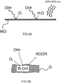
- the metal oxide photocatalyst element (MO) When the metal oxide photocatalyst element (MO) is irradiated by radiation having wavelenght in the range of [280; 500] nm, as illustrated by Fig.4A , electron and hole pairs are generated at the surface of the metal oxide photocatalyst element (MO). Electron and hole pairs further react with O 2 and H 2 O contained in the air of the chamber C to form free radicals of hydroxide OH*. Then, as illustrated in Fig.4B , if the garment G contains some natural fibers of the form R-OH, where R represents any organic radical, OH• extracts H from R-OH to form organic free radical R•. For example, natural fibers may correspond to cotton, linen, wool.
- R corresponds to CH 2 .
- the free radical R• then reacts with O 2 in the air to form organic peroxide ROOR which is one contributor (among others) to generate the so-called "smell of the sun.
- the lighting system (LS) is adapted to emit an ultraviolet radiation in the UVB range [280; 315] nm
- MO metal oxide photocatalyst element
- the reaction occurring in the chamber C can be summarized as follows: TiO 2 + UVB ⁇ e - (electron) + h + (hole) h + (hole) + H 2 O ⁇ OH • + H+ e - (electron) + O 2 ⁇ O 2 •- O2 •- + 2H 2 O ⁇ 2 OH • + 2OH - + O 2
- the metal oxide photocatalyst element (MO) takes the form of at least one layer disposed on a wall of the chamber (C), the wall being taken among the set defined by bottom wall, lateral wall, rear wall, front wall, and top wall.
- Statement “on a wall” refers either to configurations where the at least one layer is contact with the wall, or where the at least one layer is at proximity of the wall. This implies that any combination of those different positions for the metal oxide photocatalyst element (MO) is also possible.
- the layer of metal oxide photocatalyst element (MO) does not necessarily covers all the surface of the corresponding wall.
- the surface of the plate of metal oxide photocatalyst element (MO) covers at least 1% of the surface of the wall it is disposed thereon.
- the layer of metal oxide photocatalyst element (MO) either corresponds to a plate coated with metal oxide photocatalyst element (MO) and fixed on a wall of the chamber, or to a coating of metal oxide photocatalyst element (MO) directly made on a wall of the chamber C.
- the coating of metal oxide photocatalyst element (MO) has a thickness of a few nanometers.
- the layer of metal oxide photocatalyst element (MO) either forms a unique surface, or a plurality of separate surfaces disposed at different locations on wall(s) of the chamber C.
- the lighting system (LS) is disposed adjacent to a given wall of the chamber (C) taken among the set defined by bottom wall, lateral wall, rear wall, front wall, and top wall.
- the lighting system (LS) is not necessarily disposed on the same wall as the wall on which the metal oxide photocatalyst element (MO) is disposed thereon.
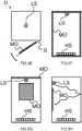
- the radiation can irradiate the metal oxide photocatalyst element (MO) at least partly by direct radiation (as illustrated in Fig.5A to Fig.5G ), and/or at least partly by indirect radiation (via reflection of the radiation on the various internal wall(s) of the chamber C, as illustrated in Fig.5H ).
- the lighting system (LS) and the metal oxide photocatalyst element (MO) are disposed adjacent to a same given wall of the chamber (C) taken among the set defined by bottom wall, lateral wall, rear wall, front wall, and top wall.
- Having the lighting system (LS) adjacent to a wall on which the metal oxide photocatalyst element (MO) is also disposed ensures a better irradiation of the metal oxide photocatalyst element (MO) to the radiation. As a result, the generation of free radicals OH• is improved. This characteristic is illustrated for example on Fig.5D , Fig.5F, and Fig.5G .
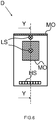
- FIG.6 illustrates a garment care device (D) according to the invention where the metal oxide photocatalyst element (MO) is disposed for one part on the top wall of the chamber (C) and for a second part on the rear wall of the chamber (C).
- the lighting system (LS) is for one part disposed adjacent to the metal oxide photocatalyst element (MO) disposed on the top wall, and for a second part disposed adjacent to the metal oxide photocatalyst element (MO) disposed on the rear wall of the chamber (C).
- the metal oxide photocatalyst element (MO) takes the form of a radiation reflector (LR) disposed between the lighting system (LS) and the same given wall on which the metal oxide photocatalyst element (MO) is disposed.
- the radiation reflector (LR) ensures that a larger surface of the metal oxide photocatalyst element (MO) is directly irradiated by the radiation. As a result, the generation of free radicals OH• is further improved.
- the radiation reflector (LR) also allows to direct the radiation towards the garments in order to improve the sanitizing effect. For example, as illustrated, the radiation reflector (LR) forms a concave angle.
- the metal oxide photocatalyst element (MO) takes the form of a perforated cover (PC).
- the lighting system (LS) is disposed between the metal oxide photocatalyst element (MO) and the wall the metal oxide photocatalyst element (MO) is facing.
- the plurality of openings formed in the perforated cover (PC) contributes to a more even reaction between the radiation and the metal oxide photocatalyst element (MO).
- the metal oxide photocatalyst element (MO) is chosen among the set of metal oxides defined by titanium dioxide having chemical formula TiO 2 , iron oxide having chemical formula FeO, iron oxide having chemical formula Fe 2 O 3 , and iron oxide having chemical formula Fe 3 O 4 . It is noted that any other metal oxide photocatalysts could be used as long as they can form free radicals OH• when irradiated by the radiation having wavelength in the range [280; 500] nm.
- the lighting system (LS) is adapted to emit radiation with wavelength in the Ultraviolet A (UVA) range [315; 400] nm, which is advantageous considering the current relatively cheaper price of the corresponding lighting system.
- UVA Ultraviolet A
- the lighting system (LS) is adapted to emit radiation with wavelength in the Ultraviolet B (UVB) range [280; 315] nm.
- UVB Ultraviolet B
- the lighting system (LS) comprises a single light bulb, or a single light tube.
- the lighting system (LS) comprises a plurality of lighting units, such as a plurality of light bulbs, and/or a plurality of lighting tubes.
- the lighting system (LS) is adapted to emit radiation with a lighting energy of at least 2 kilo Joules/m2, for example 4 kilo Joules/m2. This ensures that the metal oxide photocatalyst element (MO) and the surface of garment receive sufficient amount of energy.
- the garment care device (D) further comprises a first fan (F1) to circulate air inside the chamber (C).
- a first fan (F1) to circulate air inside the chamber (C).
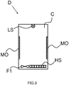
- FIG.9 An example of this preferred embodiment is depicted in Fig.9 . This embodiment is based on the embodiment depicted in Fig.3 , with an additional first fan F1 disposed on the bottom wall of the chamber C.
- the first fan F1 allows blowing air inside the chamber, so that the heated air is more evenly distributed and circulated inside the chamber C. This contributes to a faster and more efficient drying of the garments.
- the first fan F1 can be disposed at any other positions in the chamber C, such as near the top wall or the lateral walls of the chamber C.
- the garment care device (D) further comprises an external shell (ES) enclosing the chamber (C).
- the heating system (HS) and the first fan (F1) are disposed in an air channel (AC) formed between the external shell (ES) and the chamber (C), to circulate a flow of hot air in the chamber (C).
- This circulation of hot air inside the chamber C contributes to a faster and more efficient drying of the garments,.
- FIG.10 A first example of an embodiment using the first fan F1 is depicted in Fig.10 .
- This embodiment is based on the embodiment depicted in Fig.6 with a representation along axis Y-Y, and comprising an additional external shell (ES).
- the flow of hot air is illustrated by the various arrows in dotted line style.
- the flow of hot air is circulated in the air channel (AC) which extends below the bottom wall and behind the rear wall of the chamber C.
- the first fan F1 and the heating system (HS) are for example disposed in the air channel AC below the bottom wall of the chamber C.
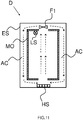
- FIG.11 A second example of an embodiment using the first fan F1 is depicted in Fig.11 .
- This embodiment is based on the embodiment depicted in Fig.5F , and comprising an additional external shell (ES).
- the flow of hot air is illustrated by the various arrows in dotted line style.
- the flow of hot air is circulated in the air channel (AC) which extends below the bottom wall and behind the two lateral walls of the chamber C.
- the first fan F1 is disposed in the air channel AC above the top wall of the chamber C.
- the heating system (HS) is disposed in the air channel AC below the bottom wall of the chamber C. It is noted that the position of the first fan F1 and the position of the heating system (HS) could be interchanged to achieve a similar result.
- the first fan (F1) is adapted to circulate a flow of hot air in the chamber (C) with a speed in the range [0.01; 1] m/s.
- the speed of the air flow can be adjusted by varying the rotation speed of the first fan (F1). The higher air is circulated in the chamber the faster the drying of garment.
- the garment care device (D) further comprises a second fan (F2) to draw air out of the chamber (C).
- a second fan (F2) to draw air out of the chamber (C).
- the humidity of air inside the chamber C can be removed, in order to increase the drying of garments.
- the second fan (F2) is activated when the humidity level in the chamber C exceeds a given threshold.
- FIG.12 A first example of an embodiment using the second fan F2 is depicted in Fig.12 .
- This embodiment is based on the embodiment depicted in Fig.9 .
- the flow of air which is drawn from the chamber C is illustrated by the arrow in dotted line style.
- the second fan F2 is preferably disposed in the upper part of the chamber C, for example along a lateral wall of the chamber C (as illustrated), or the rear wall of the chamber C (not shown).
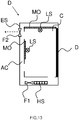
- FIG.13 A second example of an embodiment using the second fan F2 is depicted in Fig.13 . This embodiment is based on the embodiment depicted in Fig. 10 .
- the flow of air drawn from the chamber C is illustrated by the arrow in dotted line style.
- the second fan F2 is preferably disposed in the upper part of the chamber C, for example along a lateral wall of the chamber C (not shown), or the rear wall of the chamber C (as illustrated).
- a method (not illustrated by a flow chart) of treating a garment in a garment care device (D) as described above and comprising:
- the method comprises the step of disposing the at least one garment (G) within the chamber (C) such that the at least one garment (G) remains spaced from the metal oxide photocatalyst element (MO).
Landscapes
- Textile Engineering (AREA)
- Engineering & Computer Science (AREA)
- Health & Medical Sciences (AREA)
- General Health & Medical Sciences (AREA)
- Chemical Kinetics & Catalysis (AREA)
- Epidemiology (AREA)
- Life Sciences & Earth Sciences (AREA)
- Animal Behavior & Ethology (AREA)
- Chemical & Material Sciences (AREA)
- Public Health (AREA)
- Veterinary Medicine (AREA)
- Accessory Of Washing/Drying Machine, Commercial Washing/Drying Machine, Other Washing/Drying Machine (AREA)
- Professional, Industrial, Or Sporting Protective Garments (AREA)
- Catalysts (AREA)
- Drying Of Solid Materials (AREA)
- Detail Structures Of Washing Machines And Dryers (AREA)
Claims (14)
- Dispositif d'entretien de vêtement (D) comprenant :- une chambre (C) pour recevoir au moins un vêtement (G),- un système de chauffage (HS) pour chauffer ledit au moins un vêtement (G),- un système d'éclairage (LS) pour émettre à l'intérieur de ladite chambre (C), un rayonnement ayant une longueur d'onde comprise dans la plage de 280 nm à 500 nm,- un élément photocatalyseur d'oxyde métallique (MO) disposé à l'intérieur de ladite chambre (C) de sorte que l'élément photocatalyseur d'oxyde métallique (MO) peut recevoir ledit rayonnement,- dans lequel la chambre (C) comprend des moyens de réception (H, T) pour recevoir ledit au moins un vêtement (G) de sorte que ledit au moins un vêtement (G) reste espacé dudit élément photocatalyseur d'oxyde métallique (MO), caractérisé en ce que ledit élément photocatalyseur d'oxyde métallique (MO) prend la forme d'au moins une couche en contact avec une paroi de ladite chambre (C), ladite paroi étant prise parmi l'ensemble défini par une paroi inférieure, une paroi latérale, une paroi arrière, une paroi avant, et une paroi supérieure.
- Dispositif d'entretien de vêtement (D) selon la revendication 1, dans lequel ledit système d'éclairage (LS) est disposé de manière adjacente à une paroi donnée de ladite chambre (C), ladite paroi donnée étant prise parmi l'ensemble défini par une paroi inférieure, une paroi latérale, une paroi arrière, une paroi avant et une paroi supérieure.
- Dispositif d'entretien de vêtement (D) selon l'une quelconque des revendications précédentes, dans lequel ledit élément photocatalyseur d'oxyde métallique (MO) est choisi parmi l'ensemble d'oxydes métalliques définis par du dioxyde de titane ayant une formule chimique TiO2, de l'oxyde de fer ayant une formule chimique FeO, de l'oxyde de fer ayant une formule chimique Fe2O3, et de l'oxyde de fer ayant une formule chimique Fe3O4.
- Dispositif d'entretien de vêtement (D) selon l'une quelconque des revendications précédentes, comprenant en outre un premier ventilateur (F1) pour faire circuler de l'air à l'intérieur de ladite chambre (C).
- Dispositif d'entretien de vêtement (D) selon la revendication 4, comprenant en outre une coque externe (ES) comprenant ladite chambre (C), ledit système de chauffage (HS) et ledit premier ventilateur (F1) étant disposé dans un canal d'air (AC) formé entre ladite coque externe (ES) et ladite chambre (C), pour faire circuler un flux d'air chaud dans ladite chambre (C).
- Dispositif d'entretien de vêtement (D) selon la revendication 5, dans lequel ledit premier ventilateur (F1) est conçu pour faire circuler un flux d'air chaud dans ladite chambre (C) dans la plage de 0,01 m/s à 2 m/s.
- Dispositif d'entretien de vêtement (D) selon la revendication 4, comprenant en outre un second ventilateur (F2) pour attirer de l'air hors de ladite chambre (C).
- Dispositif d'entretien de vêtement (D) selon l'une quelconque des revendications 1 à 7, dans lequel ledit système d'éclairage (LS) est conçu pour émettre ledit rayonnement avec une longueur d'onde dans la plage de 315 nm à 400 nm.
- Dispositif d'entretien de vêtement (D) selon l'une quelconque des revendications 1 à 7, dans lequel ledit système d'éclairage (LS) est conçu pour émettre ledit rayonnement avec une longueur d'onde dans la plage de 280 nm à 315 nm.
- Dispositif d'entretien de vêtement (D) selon l'une quelconque des revendications 1 à 7, dans lequel ledit système d'éclairage (LS) comprend une pluralité d'unités d'éclairage.
- Dispositif d'entretien de vêtement (D) selon l'une quelconque des revendications 8, 9 ou 10, dans lequel ledit système d'éclairage (LS) est conçu pour émettre ledit rayonnement avec une énergie d'éclairage d'au moins 2 kilo Joules/m2.
- Procédé de traitement d'un vêtement dans un dispositif d'entretien de vêtement (D) comprenant :- une chambre (C) pour recevoir au moins un vêtement (G),- un système de chauffage (HS) pour chauffer ledit au moins un vêtement (G),- un système d'éclairage (LS) pour émettre à l'intérieur de ladite chambre (C), un rayonnement ayant une longueur d'onde dans la plage de 280 nm à 500 nm,- un élément photocatalyseur d'oxyde métallique (MO) disposé à l'intérieur de ladite chambre (C) de sorte que l'élément photocatalyseur d'oxyde métallique (MO) puisse recevoir ledit rayonnement,le procédé comprenant l'étape consistant à :- disposer ledit au moins un vêtement (G) dans la chambre (C) de sorte que ledit au moins un vêtement (G) reste espacé de l'élément photocatalyseur d'oxyde métallique (MO), caractérisé en ce que ledit élément photocatalyseur d'oxyde métallique (MO) prend la forme d'au moins une couche en contact avec une paroi de ladite chambre (C), ladite paroi étant prise parmi l'ensemble défini par la paroi inférieure, la paroi latérale, la paroi arrière, la paroi avant et la paroi supérieure.
- Dispositif d'entretien de vêtement (D) comprenant :- une chambre (C) pour recevoir au moins un vêtement (G) ;- un système de chauffage (HS) pour chauffer ledit au moins un vêtement (G),- un système d'éclairage (LS) pour émettre à l'intérieur de ladite chambre (C), un rayonnement ayant une longueur d'onde dans la plage de 280 nm à 500 nm,- un élément photocatalyseur d'oxyde métallique (MO) disposé à l'intérieur de ladite chambre (C) de sorte que l'élément photocatalyseur d'oxyde métallique (MO) puisse recevoir ledit rayonnement,dans lequel la chambre (C) comprend des moyens de réception (H, T) pour recevoir ledit au moins un vêtement (G), de sorte que ledit au moins un vêtement (G) reste espacé dudit élément photocatalyseur d'oxyde métallique (MO), caractérisé en ce que :- ledit système d'éclairage (LS) et ledit élément photocatalyseur d'oxyde métallique (MO) sont disposés de manière adjacente à une même paroi donnée de ladite chambre (C), ladite même paroi donnée étant prise parmi l'ensemble défini par une paroi inférieure, une paroi latérale, une paroi arrière, une paroi avant, et une paroi supérieure, et- ledit élément photocatalyseur d'oxyde métallique (MO) prend la forme d'un réflecteur de radiation (LR) disposé entre ledit système d'éclairage (LS) et ladite même paroi donnée.
- Dispositif d'entretien de vêtement (D) comprenant :- une chambre (C) pour recevoir au moins un vêtement (G),- un système de chauffage (HS) pour chauffer ledit au moins un vêtement (G),- un système d'éclairage (LS) pour émettre à l'intérieur de ladite chambre (C), un rayonnement ayant une longueur d'onde dans la plage de 280 nm à 500 nm,- un élément photocatalyseur d'oxyde métallique (MO) disposé à l'intérieur de ladite chambre (C) de sorte que l'élément photocatalyseur d'oxyde métallique (MO) puisse recevoir ledit rayonnement, dans lequel la chambre (C) comprend des moyens de réception (H ; T) pour recevoir ledit au moins un vêtement (G) de sorte que ledit au moins un vêtement (G) reste espacé dudit élément photocatalyseur d'oxyde métallique (MO), caractérisé en ce que- ledit système d'éclairage (LS) et ledit élément photocatalyseur d'oxyde métallique (MO) sont disposés de manière adjacente à une même paroi donnée de ladite chambre (C), ladite même paroi donnée étant prise parmi l'ensemble défini par une paroi inférieure, une paroi latérale, une paroi arrière, une paroi avant, et une paroi supérieure, et- ledit élément photocatalyseur d'oxyde métallique (MO) prend la forme d'un couvercle perforé (PC), ledit système d'éclairage (LS) étant disposé entre ledit élément photocatalyseur d'oxyde métallique (MO) et ladite même paroi donnée.
Priority Applications (1)
| Application Number | Priority Date | Filing Date | Title |
|---|---|---|---|
| PL16703475T PL3172374T3 (pl) | 2015-02-03 | 2016-02-02 | Urządzenie do dbałego obchodzenia się z ubraniami do suszenia i dezynfekcji ubrań oraz sposób obróbki ubrań w urządzeniu do dbałego obchodzenia się z ubraniami |
Applications Claiming Priority (2)
| Application Number | Priority Date | Filing Date | Title |
|---|---|---|---|
| EP15153528 | 2015-02-03 | ||
| PCT/EP2016/052196 WO2016124606A1 (fr) | 2015-02-03 | 2016-02-02 | Dispositif d'entretien de vêtement servant à sécher et désinfecter des vêtements |
Publications (2)
| Publication Number | Publication Date |
|---|---|
| EP3172374A1 EP3172374A1 (fr) | 2017-05-31 |
| EP3172374B1 true EP3172374B1 (fr) | 2019-04-17 |
Family
ID=52465208
Family Applications (1)
| Application Number | Title | Priority Date | Filing Date |
|---|---|---|---|
| EP16703475.0A Active EP3172374B1 (fr) | 2015-02-03 | 2016-02-02 | Dispositif d'entretien de vêtement servant à sécher et désinfecter des vêtements et procédé de traitement des vêtements |
Country Status (9)
| Country | Link |
|---|---|
| US (1) | US20180010289A1 (fr) |
| EP (1) | EP3172374B1 (fr) |
| JP (1) | JP6279811B2 (fr) |
| CN (1) | CN106687643A (fr) |
| ES (1) | ES2734132T3 (fr) |
| PL (1) | PL3172374T3 (fr) |
| RU (1) | RU2694916C2 (fr) |
| TR (1) | TR201909060T4 (fr) |
| WO (1) | WO2016124606A1 (fr) |
Families Citing this family (5)
| Publication number | Priority date | Publication date | Assignee | Title |
|---|---|---|---|---|
| RU2698329C2 (ru) * | 2014-06-30 | 2019-08-26 | Конинклейке Филипс Н.В. | Средство для дезинфекции одежды |
| WO2019094355A1 (fr) * | 2017-11-07 | 2019-05-16 | Secco Labs, Inc. | Dispositif et procédé pour sécher des vêtements |
| CN109876170A (zh) * | 2019-04-19 | 2019-06-14 | 广东好太太科技集团股份有限公司 | 一种应用于电动晾衣机的照明消毒一体式装置及运行方法 |
| FR3103832B1 (fr) * | 2019-11-29 | 2021-10-29 | Seb Sa | Procédé de défroissage d’un vêtement |
| CN113802353A (zh) * | 2020-06-12 | 2021-12-17 | 无锡小天鹅电器有限公司 | 衣物处理装置的除异味控制方法及衣物处理装置 |
Citations (1)
| Publication number | Priority date | Publication date | Assignee | Title |
|---|---|---|---|---|
| KR20060018432A (ko) * | 2004-08-24 | 2006-03-02 | 서울반도체 주식회사 | 살균 건조기 |
Family Cites Families (24)
| Publication number | Priority date | Publication date | Assignee | Title |
|---|---|---|---|---|
| DK171306B1 (da) * | 1994-06-06 | 1996-09-02 | Kaj Jensen | Fremgangsmåde og apparat til begrænsning af vegetation, hvor denne er uønsket |
| JPH10235091A (ja) * | 1997-02-26 | 1998-09-08 | Hitachi Ltd | 乾燥機及び衣類乾燥機 |
| JPH11207096A (ja) * | 1998-01-21 | 1999-08-03 | Hitachi Ltd | 衣類乾燥機 |
| JPH11207097A (ja) * | 1998-01-21 | 1999-08-03 | Hitachi Ltd | 衣類収納庫 |
| JP2005253786A (ja) * | 2004-03-12 | 2005-09-22 | Sanyo Electric Co Ltd | 洗濯機 |
| US6941673B1 (en) * | 2004-06-12 | 2005-09-13 | National Pintung University Of Science And Technology | Multi-function closed-type drying system with solar energy collection arrangement |
| WO2006135273A1 (fr) * | 2005-06-17 | 2006-12-21 | Adam Mendeleevich Abramov | Procede de sechage antifongique et antibacterien pour chaussures et appareil d'electrosechage de chaussures par traitement thermique et ultraviolets |
| US9732462B2 (en) * | 2005-11-18 | 2017-08-15 | Lg Electronics Inc. | Sterilizable drying machine using ultraviolet radiation and sterilizable drying method in the same |
| CN101173460A (zh) * | 2006-10-30 | 2008-05-07 | 海尔集团公司 | 一种无水洗涤方法及无水洗衣装置 |
| US20080201979A1 (en) * | 2007-02-23 | 2008-08-28 | Rhoades Dean L | Illuminating hair styling system |
| KR101366331B1 (ko) * | 2007-06-13 | 2014-02-20 | 엘지전자 주식회사 | 의류건조장치 및 그 제어방법 |
| EP2113605B1 (fr) * | 2008-04-23 | 2013-11-06 | Electrolux Home Products Corporation N.V. | Lave et/ou séche linge domestique et son procédé de fonctionnement |
| KR101035400B1 (ko) * | 2008-08-26 | 2011-05-23 | (주)케이비시스템 | 빨래건조장치 |
| US20110212185A1 (en) * | 2008-09-16 | 2011-09-01 | Kenichiro Tanaka | Water that expresses pathogen-resistance genes (pr gene clusters) to encode plant immunoproteins, a method of preventing plant diseases using the water, and a device for producing the water |
| DE102009026712A1 (de) * | 2009-06-04 | 2010-12-09 | BSH Bosch und Siemens Hausgeräte GmbH | Hausgerät mit einer Oberfläche, welche einen Photokatalysator aufweist |
| EP2213947A3 (fr) * | 2010-01-28 | 2010-10-06 | V-Zug AG | Appareil domestique avec photocatalyseur |
| JP2012125352A (ja) * | 2010-12-14 | 2012-07-05 | Samsung Electronics Co Ltd | 衣類乾燥機 |
| PL2330247T3 (pl) * | 2011-03-08 | 2013-08-30 | V Zug Ag | Suszarka do ubrań, zwłaszcza suszarka komorowa |
| KR20130047850A (ko) * | 2011-11-01 | 2013-05-09 | 삼성전자주식회사 | 정수 장치 및 상기 정수 장치를 포함하는 세탁기 |
| US10246817B2 (en) * | 2012-11-02 | 2019-04-02 | Koninklijke Philips N.V. | Treatment of a fabric article |
| JP5655872B2 (ja) * | 2013-01-23 | 2015-01-21 | 三菱電機株式会社 | 衣類メンテナンス装置 |
| EP2759633B1 (fr) * | 2013-01-29 | 2015-10-21 | V-Zug AG | Appareil ménager avec nettoyage catalytique |
| CN104109971B (zh) * | 2013-04-22 | 2018-02-23 | 青岛海尔洗衣机有限公司 | 一种设置杀菌除味装置的干衣机 |
| WO2015002326A1 (fr) * | 2013-07-05 | 2015-01-08 | Nitto Denko Corporation | Feuille de photocatalyseur |
-
2016
- 2016-02-02 EP EP16703475.0A patent/EP3172374B1/fr active Active
- 2016-02-02 WO PCT/EP2016/052196 patent/WO2016124606A1/fr not_active Ceased
- 2016-02-02 RU RU2017113641A patent/RU2694916C2/ru active
- 2016-02-02 JP JP2017514866A patent/JP6279811B2/ja not_active Expired - Fee Related
- 2016-02-02 ES ES16703475T patent/ES2734132T3/es active Active
- 2016-02-02 CN CN201680002607.0A patent/CN106687643A/zh active Pending
- 2016-02-02 PL PL16703475T patent/PL3172374T3/pl unknown
- 2016-02-02 US US15/505,710 patent/US20180010289A1/en not_active Abandoned
- 2016-02-02 TR TR2019/09060T patent/TR201909060T4/tr unknown
Patent Citations (1)
| Publication number | Priority date | Publication date | Assignee | Title |
|---|---|---|---|---|
| KR20060018432A (ko) * | 2004-08-24 | 2006-03-02 | 서울반도체 주식회사 | 살균 건조기 |
Also Published As
| Publication number | Publication date |
|---|---|
| US20180010289A1 (en) | 2018-01-11 |
| RU2694916C2 (ru) | 2019-07-18 |
| PL3172374T3 (pl) | 2019-09-30 |
| JP6279811B2 (ja) | 2018-02-14 |
| CN106687643A (zh) | 2017-05-17 |
| RU2017113641A3 (fr) | 2019-05-24 |
| RU2017113641A (ru) | 2018-10-23 |
| ES2734132T3 (es) | 2019-12-04 |
| WO2016124606A1 (fr) | 2016-08-11 |
| JP2017529157A (ja) | 2017-10-05 |
| EP3172374A1 (fr) | 2017-05-31 |
| TR201909060T4 (tr) | 2019-07-22 |
Similar Documents
| Publication | Publication Date | Title |
|---|---|---|
| EP3172374B1 (fr) | Dispositif d'entretien de vêtement servant à sécher et désinfecter des vêtements et procédé de traitement des vêtements | |
| JP6342911B2 (ja) | 布製品の処置 | |
| JP3739377B2 (ja) | 洗濯乾燥機 | |
| CN104109971B (zh) | 一种设置杀菌除味装置的干衣机 | |
| KR20200109194A (ko) | 탈취 성능을 향상한 세탁장치 | |
| KR20140101641A (ko) | 스탠드형 간이 건조기 | |
| CN109137463A (zh) | 织物制品的处理 | |
| KR20130057340A (ko) | 옷걸이형 의류 살균 탈취기 및 그 작동 방법 | |
| KR20080055288A (ko) | 광촉매를 이용한 신발 살균 자판기 | |
| KR20090115388A (ko) | 원적외선 빨래 건조대 | |
| KR101366267B1 (ko) | 의류처리장치 | |
| JP2008029579A (ja) | 衣類乾燥機 | |
| JP2011078659A (ja) | 洗濯機および洗濯方法 | |
| CN222024715U (zh) | 洗衣机 | |
| CN221701899U (zh) | 衣物处理设备 | |
| CN222524971U (zh) | 干衣机 | |
| KR20240152609A (ko) | 3중 집중 살균 방식 및 가변 열 제어시스템이 적용된 손상 최소화 살균 건조 시스템 | |
| KR100680988B1 (ko) | 드럼 세탁기용 건조 덕트 | |
| JP2011078662A (ja) | 洗濯機および洗濯機の除菌方法 | |
| KR200403913Y1 (ko) | 순환식 열풍 건조기 | |
| KR100442458B1 (ko) | 원적외선 살균 칫솔 건조기 | |
| KR101938418B1 (ko) | 엑스선 발생기를 구비한 세탁물 건조기, 및 상기 세탁물 건조기의 제어 방법 | |
| JP3214920U (ja) | 光触媒乾燥機 | |
| KR20050108611A (ko) | 원적외선 광원이 구비된 드럼 세탁기 | |
| CN120083033A (zh) | 洗衣机 |
Legal Events
| Date | Code | Title | Description |
|---|---|---|---|
| STAA | Information on the status of an ep patent application or granted ep patent |
Free format text: STATUS: THE INTERNATIONAL PUBLICATION HAS BEEN MADE |
|
| PUAI | Public reference made under article 153(3) epc to a published international application that has entered the european phase |
Free format text: ORIGINAL CODE: 0009012 |
|
| STAA | Information on the status of an ep patent application or granted ep patent |
Free format text: STATUS: REQUEST FOR EXAMINATION WAS MADE |
|
| 17P | Request for examination filed |
Effective date: 20170224 |
|
| AK | Designated contracting states |
Kind code of ref document: A1 Designated state(s): AL AT BE BG CH CY CZ DE DK EE ES FI FR GB GR HR HU IE IS IT LI LT LU LV MC MK MT NL NO PL PT RO RS SE SI SK SM TR |
|
| AX | Request for extension of the european patent |
Extension state: BA ME |
|
| GRAP | Despatch of communication of intention to grant a patent |
Free format text: ORIGINAL CODE: EPIDOSNIGR1 |
|
| STAA | Information on the status of an ep patent application or granted ep patent |
Free format text: STATUS: GRANT OF PATENT IS INTENDED |
|
| DAV | Request for validation of the european patent (deleted) | ||
| DAX | Request for extension of the european patent (deleted) | ||
| INTG | Intention to grant announced |
Effective date: 20170808 |
|
| GRAJ | Information related to disapproval of communication of intention to grant by the applicant or resumption of examination proceedings by the epo deleted |
Free format text: ORIGINAL CODE: EPIDOSDIGR1 |
|
| STAA | Information on the status of an ep patent application or granted ep patent |
Free format text: STATUS: REQUEST FOR EXAMINATION WAS MADE |
|
| GRAP | Despatch of communication of intention to grant a patent |
Free format text: ORIGINAL CODE: EPIDOSNIGR1 |
|
| STAA | Information on the status of an ep patent application or granted ep patent |
Free format text: STATUS: GRANT OF PATENT IS INTENDED |
|
| GRAJ | Information related to disapproval of communication of intention to grant by the applicant or resumption of examination proceedings by the epo deleted |
Free format text: ORIGINAL CODE: EPIDOSDIGR1 |
|
| STAA | Information on the status of an ep patent application or granted ep patent |
Free format text: STATUS: REQUEST FOR EXAMINATION WAS MADE |
|
| STAA | Information on the status of an ep patent application or granted ep patent |
Free format text: STATUS: EXAMINATION IS IN PROGRESS |
|
| 17Q | First examination report despatched |
Effective date: 20171116 |
|
| INTC | Intention to grant announced (deleted) | ||
| RIC1 | Information provided on ipc code assigned before grant |
Ipc: D06F 58/20 20060101AFI20180906BHEP Ipc: D06F 58/26 20060101ALN20180906BHEP Ipc: D06F 58/10 20060101ALN20180906BHEP |
|
| GRAP | Despatch of communication of intention to grant a patent |
Free format text: ORIGINAL CODE: EPIDOSNIGR1 |
|
| STAA | Information on the status of an ep patent application or granted ep patent |
Free format text: STATUS: GRANT OF PATENT IS INTENDED |
|
| INTG | Intention to grant announced |
Effective date: 20181025 |
|
| GRAS | Grant fee paid |
Free format text: ORIGINAL CODE: EPIDOSNIGR3 |
|
| GRAA | (expected) grant |
Free format text: ORIGINAL CODE: 0009210 |
|
| STAA | Information on the status of an ep patent application or granted ep patent |
Free format text: STATUS: THE PATENT HAS BEEN GRANTED |
|
| AK | Designated contracting states |
Kind code of ref document: B1 Designated state(s): AL AT BE BG CH CY CZ DE DK EE ES FI FR GB GR HR HU IE IS IT LI LT LU LV MC MK MT NL NO PL PT RO RS SE SI SK SM TR |
|
| REG | Reference to a national code |
Ref country code: GB Ref legal event code: FG4D |
|
| REG | Reference to a national code |
Ref country code: CH Ref legal event code: EP |
|
| REG | Reference to a national code |
Ref country code: DE Ref legal event code: R096 Ref document number: 602016012537 Country of ref document: DE |
|
| REG | Reference to a national code |
Ref country code: AT Ref legal event code: REF Ref document number: 1121677 Country of ref document: AT Kind code of ref document: T Effective date: 20190515 Ref country code: IE Ref legal event code: FG4D |
|
| REG | Reference to a national code |
Ref country code: NL Ref legal event code: MP Effective date: 20190417 |
|
| REG | Reference to a national code |
Ref country code: LT Ref legal event code: MG4D |
|
| PG25 | Lapsed in a contracting state [announced via postgrant information from national office to epo] |
Ref country code: NL Free format text: LAPSE BECAUSE OF FAILURE TO SUBMIT A TRANSLATION OF THE DESCRIPTION OR TO PAY THE FEE WITHIN THE PRESCRIBED TIME-LIMIT Effective date: 20190417 |
|
| PG25 | Lapsed in a contracting state [announced via postgrant information from national office to epo] |
Ref country code: FI Free format text: LAPSE BECAUSE OF FAILURE TO SUBMIT A TRANSLATION OF THE DESCRIPTION OR TO PAY THE FEE WITHIN THE PRESCRIBED TIME-LIMIT Effective date: 20190417 Ref country code: NO Free format text: LAPSE BECAUSE OF FAILURE TO SUBMIT A TRANSLATION OF THE DESCRIPTION OR TO PAY THE FEE WITHIN THE PRESCRIBED TIME-LIMIT Effective date: 20190717 Ref country code: HR Free format text: LAPSE BECAUSE OF FAILURE TO SUBMIT A TRANSLATION OF THE DESCRIPTION OR TO PAY THE FEE WITHIN THE PRESCRIBED TIME-LIMIT Effective date: 20190417 Ref country code: LT Free format text: LAPSE BECAUSE OF FAILURE TO SUBMIT A TRANSLATION OF THE DESCRIPTION OR TO PAY THE FEE WITHIN THE PRESCRIBED TIME-LIMIT Effective date: 20190417 Ref country code: AL Free format text: LAPSE BECAUSE OF FAILURE TO SUBMIT A TRANSLATION OF THE DESCRIPTION OR TO PAY THE FEE WITHIN THE PRESCRIBED TIME-LIMIT Effective date: 20190417 Ref country code: SE Free format text: LAPSE BECAUSE OF FAILURE TO SUBMIT A TRANSLATION OF THE DESCRIPTION OR TO PAY THE FEE WITHIN THE PRESCRIBED TIME-LIMIT Effective date: 20190417 Ref country code: PT Free format text: LAPSE BECAUSE OF FAILURE TO SUBMIT A TRANSLATION OF THE DESCRIPTION OR TO PAY THE FEE WITHIN THE PRESCRIBED TIME-LIMIT Effective date: 20190817 |
|
| PG25 | Lapsed in a contracting state [announced via postgrant information from national office to epo] |
Ref country code: BG Free format text: LAPSE BECAUSE OF FAILURE TO SUBMIT A TRANSLATION OF THE DESCRIPTION OR TO PAY THE FEE WITHIN THE PRESCRIBED TIME-LIMIT Effective date: 20190717 Ref country code: GR Free format text: LAPSE BECAUSE OF FAILURE TO SUBMIT A TRANSLATION OF THE DESCRIPTION OR TO PAY THE FEE WITHIN THE PRESCRIBED TIME-LIMIT Effective date: 20190718 Ref country code: LV Free format text: LAPSE BECAUSE OF FAILURE TO SUBMIT A TRANSLATION OF THE DESCRIPTION OR TO PAY THE FEE WITHIN THE PRESCRIBED TIME-LIMIT Effective date: 20190417 Ref country code: RS Free format text: LAPSE BECAUSE OF FAILURE TO SUBMIT A TRANSLATION OF THE DESCRIPTION OR TO PAY THE FEE WITHIN THE PRESCRIBED TIME-LIMIT Effective date: 20190417 |
|
| REG | Reference to a national code |
Ref country code: ES Ref legal event code: FG2A Ref document number: 2734132 Country of ref document: ES Kind code of ref document: T3 Effective date: 20191204 |
|
| REG | Reference to a national code |
Ref country code: AT Ref legal event code: MK05 Ref document number: 1121677 Country of ref document: AT Kind code of ref document: T Effective date: 20190417 |
|
| PG25 | Lapsed in a contracting state [announced via postgrant information from national office to epo] |
Ref country code: IS Free format text: LAPSE BECAUSE OF FAILURE TO SUBMIT A TRANSLATION OF THE DESCRIPTION OR TO PAY THE FEE WITHIN THE PRESCRIBED TIME-LIMIT Effective date: 20190817 |
|
| REG | Reference to a national code |
Ref country code: DE Ref legal event code: R097 Ref document number: 602016012537 Country of ref document: DE |
|
| PG25 | Lapsed in a contracting state [announced via postgrant information from national office to epo] |
Ref country code: SK Free format text: LAPSE BECAUSE OF FAILURE TO SUBMIT A TRANSLATION OF THE DESCRIPTION OR TO PAY THE FEE WITHIN THE PRESCRIBED TIME-LIMIT Effective date: 20190417 Ref country code: RO Free format text: LAPSE BECAUSE OF FAILURE TO SUBMIT A TRANSLATION OF THE DESCRIPTION OR TO PAY THE FEE WITHIN THE PRESCRIBED TIME-LIMIT Effective date: 20190417 Ref country code: CZ Free format text: LAPSE BECAUSE OF FAILURE TO SUBMIT A TRANSLATION OF THE DESCRIPTION OR TO PAY THE FEE WITHIN THE PRESCRIBED TIME-LIMIT Effective date: 20190417 Ref country code: DK Free format text: LAPSE BECAUSE OF FAILURE TO SUBMIT A TRANSLATION OF THE DESCRIPTION OR TO PAY THE FEE WITHIN THE PRESCRIBED TIME-LIMIT Effective date: 20190417 Ref country code: AT Free format text: LAPSE BECAUSE OF FAILURE TO SUBMIT A TRANSLATION OF THE DESCRIPTION OR TO PAY THE FEE WITHIN THE PRESCRIBED TIME-LIMIT Effective date: 20190417 Ref country code: EE Free format text: LAPSE BECAUSE OF FAILURE TO SUBMIT A TRANSLATION OF THE DESCRIPTION OR TO PAY THE FEE WITHIN THE PRESCRIBED TIME-LIMIT Effective date: 20190417 |
|
| PLBE | No opposition filed within time limit |
Free format text: ORIGINAL CODE: 0009261 |
|
| STAA | Information on the status of an ep patent application or granted ep patent |
Free format text: STATUS: NO OPPOSITION FILED WITHIN TIME LIMIT |
|
| PG25 | Lapsed in a contracting state [announced via postgrant information from national office to epo] |
Ref country code: SM Free format text: LAPSE BECAUSE OF FAILURE TO SUBMIT A TRANSLATION OF THE DESCRIPTION OR TO PAY THE FEE WITHIN THE PRESCRIBED TIME-LIMIT Effective date: 20190417 |
|
| RAP2 | Party data changed (patent owner data changed or rights of a patent transferred) |
Owner name: KONINKLIJKE PHILIPS N.V. |
|
| 26N | No opposition filed |
Effective date: 20200120 |
|
| PG25 | Lapsed in a contracting state [announced via postgrant information from national office to epo] |
Ref country code: SI Free format text: LAPSE BECAUSE OF FAILURE TO SUBMIT A TRANSLATION OF THE DESCRIPTION OR TO PAY THE FEE WITHIN THE PRESCRIBED TIME-LIMIT Effective date: 20190417 |
|
| REG | Reference to a national code |
Ref country code: CH Ref legal event code: PL |
|
| REG | Reference to a national code |
Ref country code: BE Ref legal event code: MM Effective date: 20200229 |
|
| PG25 | Lapsed in a contracting state [announced via postgrant information from national office to epo] |
Ref country code: LU Free format text: LAPSE BECAUSE OF NON-PAYMENT OF DUE FEES Effective date: 20200202 Ref country code: MC Free format text: LAPSE BECAUSE OF FAILURE TO SUBMIT A TRANSLATION OF THE DESCRIPTION OR TO PAY THE FEE WITHIN THE PRESCRIBED TIME-LIMIT Effective date: 20190417 |
|
| PG25 | Lapsed in a contracting state [announced via postgrant information from national office to epo] |
Ref country code: CH Free format text: LAPSE BECAUSE OF NON-PAYMENT OF DUE FEES Effective date: 20200229 Ref country code: LI Free format text: LAPSE BECAUSE OF NON-PAYMENT OF DUE FEES Effective date: 20200229 |
|
| PG25 | Lapsed in a contracting state [announced via postgrant information from national office to epo] |
Ref country code: IE Free format text: LAPSE BECAUSE OF NON-PAYMENT OF DUE FEES Effective date: 20200202 |
|
| PG25 | Lapsed in a contracting state [announced via postgrant information from national office to epo] |
Ref country code: BE Free format text: LAPSE BECAUSE OF NON-PAYMENT OF DUE FEES Effective date: 20200229 |
|
| PG25 | Lapsed in a contracting state [announced via postgrant information from national office to epo] |
Ref country code: MT Free format text: LAPSE BECAUSE OF FAILURE TO SUBMIT A TRANSLATION OF THE DESCRIPTION OR TO PAY THE FEE WITHIN THE PRESCRIBED TIME-LIMIT Effective date: 20190417 Ref country code: CY Free format text: LAPSE BECAUSE OF FAILURE TO SUBMIT A TRANSLATION OF THE DESCRIPTION OR TO PAY THE FEE WITHIN THE PRESCRIBED TIME-LIMIT Effective date: 20190417 |
|
| PG25 | Lapsed in a contracting state [announced via postgrant information from national office to epo] |
Ref country code: MK Free format text: LAPSE BECAUSE OF FAILURE TO SUBMIT A TRANSLATION OF THE DESCRIPTION OR TO PAY THE FEE WITHIN THE PRESCRIBED TIME-LIMIT Effective date: 20190417 |
|
| PGFP | Annual fee paid to national office [announced via postgrant information from national office to epo] |
Ref country code: FR Payment date: 20230223 Year of fee payment: 8 Ref country code: ES Payment date: 20230321 Year of fee payment: 8 |
|
| PGFP | Annual fee paid to national office [announced via postgrant information from national office to epo] |
Ref country code: TR Payment date: 20230119 Year of fee payment: 8 Ref country code: PL Payment date: 20230124 Year of fee payment: 8 Ref country code: IT Payment date: 20230220 Year of fee payment: 8 Ref country code: GB Payment date: 20230214 Year of fee payment: 8 Ref country code: DE Payment date: 20230227 Year of fee payment: 8 |
|
| REG | Reference to a national code |
Ref country code: GB Ref legal event code: 732E Free format text: REGISTERED BETWEEN 20231214 AND 20231220 |
|
| REG | Reference to a national code |
Ref country code: DE Ref legal event code: R119 Ref document number: 602016012537 Country of ref document: DE |
|
| GBPC | Gb: european patent ceased through non-payment of renewal fee |
Effective date: 20240202 |
|
| PG25 | Lapsed in a contracting state [announced via postgrant information from national office to epo] |
Ref country code: DE Free format text: LAPSE BECAUSE OF NON-PAYMENT OF DUE FEES Effective date: 20240903 |
|
| PG25 | Lapsed in a contracting state [announced via postgrant information from national office to epo] |
Ref country code: GB Free format text: LAPSE BECAUSE OF NON-PAYMENT OF DUE FEES Effective date: 20240202 |
|
| PG25 | Lapsed in a contracting state [announced via postgrant information from national office to epo] |
Ref country code: FR Free format text: LAPSE BECAUSE OF NON-PAYMENT OF DUE FEES Effective date: 20240229 |
|
| PG25 | Lapsed in a contracting state [announced via postgrant information from national office to epo] |
Ref country code: GB Free format text: LAPSE BECAUSE OF NON-PAYMENT OF DUE FEES Effective date: 20240202 Ref country code: FR Free format text: LAPSE BECAUSE OF NON-PAYMENT OF DUE FEES Effective date: 20240229 Ref country code: DE Free format text: LAPSE BECAUSE OF NON-PAYMENT OF DUE FEES Effective date: 20240903 |
|
| PG25 | Lapsed in a contracting state [announced via postgrant information from national office to epo] |
Ref country code: IT Free format text: LAPSE BECAUSE OF NON-PAYMENT OF DUE FEES Effective date: 20240202 |
|
| REG | Reference to a national code |
Ref country code: ES Ref legal event code: FD2A Effective date: 20250326 |
|
| PG25 | Lapsed in a contracting state [announced via postgrant information from national office to epo] |
Ref country code: ES Free format text: LAPSE BECAUSE OF NON-PAYMENT OF DUE FEES Effective date: 20240203 |