EP3172425B1 - Intake module having integrated exhaust gas recirculation for an internal combustion engine - Google Patents
Intake module having integrated exhaust gas recirculation for an internal combustion engine Download PDFInfo
- Publication number
- EP3172425B1 EP3172425B1 EP15723982.3A EP15723982A EP3172425B1 EP 3172425 B1 EP3172425 B1 EP 3172425B1 EP 15723982 A EP15723982 A EP 15723982A EP 3172425 B1 EP3172425 B1 EP 3172425B1
- Authority
- EP
- European Patent Office
- Prior art keywords
- exhaust gas
- distribution line
- gas distribution
- intake module
- intercooler
- Prior art date
- Legal status (The legal status is an assumption and is not a legal conclusion. Google has not performed a legal analysis and makes no representation as to the accuracy of the status listed.)
- Not-in-force
Links
- 238000002485 combustion reaction Methods 0.000 title claims description 29
- 238000009826 distribution Methods 0.000 claims description 116
- 239000012530 fluid Substances 0.000 claims description 54
- 239000002826 coolant Substances 0.000 claims description 23
- 239000007789 gas Substances 0.000 description 284
- 238000002156 mixing Methods 0.000 description 89
- 238000011109 contamination Methods 0.000 description 3
- 238000004519 manufacturing process Methods 0.000 description 3
- 239000000203 mixture Substances 0.000 description 3
- 238000009827 uniform distribution Methods 0.000 description 3
- 230000001154 acute effect Effects 0.000 description 2
- 230000015572 biosynthetic process Effects 0.000 description 2
- 230000001419 dependent effect Effects 0.000 description 2
- 238000000034 method Methods 0.000 description 2
- 230000002093 peripheral effect Effects 0.000 description 2
- 230000003134 recirculating effect Effects 0.000 description 2
- 238000009825 accumulation Methods 0.000 description 1
- 238000004364 calculation method Methods 0.000 description 1
- 230000005465 channeling Effects 0.000 description 1
- 238000001816 cooling Methods 0.000 description 1
- 238000007599 discharging Methods 0.000 description 1
- 239000003344 environmental pollutant Substances 0.000 description 1
- 230000003116 impacting effect Effects 0.000 description 1
- 230000003993 interaction Effects 0.000 description 1
- 238000002955 isolation Methods 0.000 description 1
- 239000002184 metal Substances 0.000 description 1
- 230000000149 penetrating effect Effects 0.000 description 1
- 231100000719 pollutant Toxicity 0.000 description 1
- 230000002250 progressing effect Effects 0.000 description 1
- 238000004088 simulation Methods 0.000 description 1
- 230000001550 time effect Effects 0.000 description 1
Images


Classifications
-
- F—MECHANICAL ENGINEERING; LIGHTING; HEATING; WEAPONS; BLASTING
- F02—COMBUSTION ENGINES; HOT-GAS OR COMBUSTION-PRODUCT ENGINE PLANTS
- F02B—INTERNAL-COMBUSTION PISTON ENGINES; COMBUSTION ENGINES IN GENERAL
- F02B29/00—Engines characterised by provision for charging or scavenging not provided for in groups F02B25/00, F02B27/00 or F02B33/00 - F02B39/00; Details thereof
- F02B29/04—Cooling of air intake supply
- F02B29/045—Constructional details of the heat exchangers, e.g. pipes, plates, ribs, insulation, materials, or manufacturing and assembly
- F02B29/0475—Constructional details of the heat exchangers, e.g. pipes, plates, ribs, insulation, materials, or manufacturing and assembly the intake air cooler being combined with another device, e.g. heater, valve, compressor, filter or EGR cooler, or being assembled on a special engine location
-
- F—MECHANICAL ENGINEERING; LIGHTING; HEATING; WEAPONS; BLASTING
- F02—COMBUSTION ENGINES; HOT-GAS OR COMBUSTION-PRODUCT ENGINE PLANTS
- F02M—SUPPLYING COMBUSTION ENGINES IN GENERAL WITH COMBUSTIBLE MIXTURES OR CONSTITUENTS THEREOF
- F02M26/00—Engine-pertinent apparatus for adding exhaust gases to combustion-air, main fuel or fuel-air mixture, e.g. by exhaust gas recirculation [EGR] systems
- F02M26/13—Arrangement or layout of EGR passages, e.g. in relation to specific engine parts or for incorporation of accessories
- F02M26/17—Arrangement or layout of EGR passages, e.g. in relation to specific engine parts or for incorporation of accessories in relation to the intake system
- F02M26/19—Means for improving the mixing of air and recirculated exhaust gases, e.g. venturis or multiple openings to the intake system
-
- F—MECHANICAL ENGINEERING; LIGHTING; HEATING; WEAPONS; BLASTING
- F02—COMBUSTION ENGINES; HOT-GAS OR COMBUSTION-PRODUCT ENGINE PLANTS
- F02M—SUPPLYING COMBUSTION ENGINES IN GENERAL WITH COMBUSTIBLE MIXTURES OR CONSTITUENTS THEREOF
- F02M35/00—Combustion-air cleaners, air intakes, intake silencers, or induction systems specially adapted for, or arranged on, internal-combustion engines
- F02M35/10—Air intakes; Induction systems
- F02M35/10209—Fluid connections to the air intake system; their arrangement of pipes, valves or the like
- F02M35/10222—Exhaust gas recirculation [EGR]; Positive crankcase ventilation [PCV]; Additional air admission, lubricant or fuel vapour admission
-
- F—MECHANICAL ENGINEERING; LIGHTING; HEATING; WEAPONS; BLASTING
- F02—COMBUSTION ENGINES; HOT-GAS OR COMBUSTION-PRODUCT ENGINE PLANTS
- F02M—SUPPLYING COMBUSTION ENGINES IN GENERAL WITH COMBUSTIBLE MIXTURES OR CONSTITUENTS THEREOF
- F02M35/00—Combustion-air cleaners, air intakes, intake silencers, or induction systems specially adapted for, or arranged on, internal-combustion engines
- F02M35/10—Air intakes; Induction systems
- F02M35/1034—Manufacturing and assembling intake systems
- F02M35/10354—Joining multiple sections together
-
- F—MECHANICAL ENGINEERING; LIGHTING; HEATING; WEAPONS; BLASTING
- F02—COMBUSTION ENGINES; HOT-GAS OR COMBUSTION-PRODUCT ENGINE PLANTS
- F02M—SUPPLYING COMBUSTION ENGINES IN GENERAL WITH COMBUSTIBLE MIXTURES OR CONSTITUENTS THEREOF
- F02M35/00—Combustion-air cleaners, air intakes, intake silencers, or induction systems specially adapted for, or arranged on, internal-combustion engines
- F02M35/10—Air intakes; Induction systems
- F02M35/104—Intake manifolds
- F02M35/112—Intake manifolds for engines with cylinders all in one line
-
- F—MECHANICAL ENGINEERING; LIGHTING; HEATING; WEAPONS; BLASTING
- F02—COMBUSTION ENGINES; HOT-GAS OR COMBUSTION-PRODUCT ENGINE PLANTS
- F02B—INTERNAL-COMBUSTION PISTON ENGINES; COMBUSTION ENGINES IN GENERAL
- F02B29/00—Engines characterised by provision for charging or scavenging not provided for in groups F02B25/00, F02B27/00 or F02B33/00 - F02B39/00; Details thereof
- F02B29/04—Cooling of air intake supply
- F02B29/045—Constructional details of the heat exchangers, e.g. pipes, plates, ribs, insulation, materials, or manufacturing and assembly
- F02B29/0462—Liquid cooled heat exchangers
-
- Y—GENERAL TAGGING OF NEW TECHNOLOGICAL DEVELOPMENTS; GENERAL TAGGING OF CROSS-SECTIONAL TECHNOLOGIES SPANNING OVER SEVERAL SECTIONS OF THE IPC; TECHNICAL SUBJECTS COVERED BY FORMER USPC CROSS-REFERENCE ART COLLECTIONS [XRACs] AND DIGESTS
- Y02—TECHNOLOGIES OR APPLICATIONS FOR MITIGATION OR ADAPTATION AGAINST CLIMATE CHANGE
- Y02T—CLIMATE CHANGE MITIGATION TECHNOLOGIES RELATED TO TRANSPORTATION
- Y02T10/00—Road transport of goods or passengers
- Y02T10/10—Internal combustion engine [ICE] based vehicles
- Y02T10/12—Improving ICE efficiencies
Definitions
- the present invention relates to an intake module with integrated exhaust gas recirculation for an internal combustion engine.
- Intake modules for internal combustion engines are used for sucking and introducing air from the environment into the combustion chamber of the internal combustion engine.
- one or more functional elements of the intake tract of the internal combustion engine can be integrated into such intake modules in order to take account of the fact that there is only limited space available in a motor vehicle.
- Exhaust gas recirculation is integrated into said intake module.
- the exhaust gas recirculation serves to reduce the pollutants emitted by the internal combustion engine into the environment and is based on the idea of mixing a part of the exhaust gas produced in the combustion process with the fresh air sucked in by the intake module and reintroducing it into the combustion chamber.
- Such exhaust gas recirculation systems are carried out approximately in conjunction with an exhaust gas turbocharger.
- the prior art includes so-called high-pressure or low-pressure feedback systems, depending on where in the intake or exhaust gas of the engine exhaust gas recirculation takes place.
- the EP 1 122 421 A2 a suction pipe with integrated exhaust gas recirculation system for an internal combustion engine.
- the suction pipe comprises a collecting space for sucked in from the outside fresh air.
- the collecting chamber opens an exhaust pipe, which is traversed by recirculating exhaust gas.
- the collecting space has an air inlet, which forms an angle of substantially 90 ° with the corresponding openings in the exhaust pipe.
- the fresh gas distributor comprises a plurality of fresh gas outlets, wherein each such fresh gas outlet is assigned to a specific cylinder of the internal combustion engine. Adjacent to the fresh air manifold a distribution channel of exhaust gas recirculation is provided, which communicates fluidically with the fresh air manifold.
- the US 5,957,116 describes an exhaust gas recirculation system for an internal combustion engine.
- the exhaust gas recirculation system comprises an exhaust pipe with a plurality of exhaust gas outlet openings, which are provided in a peripheral wall of the exhaust pipe.
- the exhaust pipe extends within a fresh air intake duct; Suction line and exhaust pipe extend substantially parallel to each other.
- the FR 2 967 215 A1 discloses an intake module with a mixing chamber for fresh air and exhaust gas.
- the intake module has an integrated exhaust distribution line. In this exhaust gas distribution line, the exhaust gas to be supplied to the mixing chamber is introduced off-center.
- the main object of the present invention is to provide an improved embodiment of an intake module with integrated exhaust gas recirculation, which in particular ensures a particularly uniform mixing of the exhaust gas to be recirculated with fresh air, so that over or under supply of individual cylinders with respect to the remaining cylinders with recirculating exhaust gas can be avoided as possible.
- the basic idea of the invention is accordingly to introduce exhaust gas into the latter via a substantially symmetrically realized exhaust gas supply line. In this way, set up particularly uniform pressure conditions, so that there is also an advantageous, uniformed introduction of the exhaust gas into the mixing chamber.
- an intake module comprises a casing housing bounding a housing, which has a first housing wall with at least one air inlet and second housing wall with at least one fluid outlet.
- a charge air cooler is arranged in the housing interior of the housing.
- a mixing chamber is further formed in the housing. This is part of the housing interior and is limited by the charge air cooler and the second housing wall with the at least one fluid outlet.
- an exhaust gas distribution pipe is arranged, which extends along a transverse direction of the mixing chamber.
- the intake module comprises an exhaust gas supply line, which communicates fluidically with the latter via a fluid passage provided on the exhaust gas distribution line.
- the fluid passage is arranged substantially centrally in the exhaust gas distribution line and / or in the mixing chamber with respect to the transverse direction. Such a central arrangement of the fluid passage means that the exhaust gas introduced into the exhaust gas feed line via this fluid passage can be distributed in both conduit regions of the exhaust gas supply line, from where it can be introduced into the mixing chamber via exhaust gas outlets.
- a longitudinal direction which extends orthogonal to the transverse direction is defined by a virtual connecting line between the at least one air inlet and the at least one fluid outlet.
- the exhaust gas supply line extends at least partially in a plane passing through the longitudinal direction and an orthogonal both to the longitudinal and Also transverse direction extending vertical direction is defined and in which also the fluid passage is arranged.
- the exhaust gas supply line leads to an advantageous, particularly uniform introduction of exhaust gas into the mixing chamber.
- the exhaust gas supply line may also extend in a plane defined by the transverse direction and the vertical direction in which the fluid passage is arranged.
- Said longitudinal direction can also be defined in other ways, for example by a main flow direction of the fresh air in the mixing chamber, immediately before the fresh air strikes the exhaust gas introduced from the exhaust gas distribution line into the mixing chamber.
- the distance between the exhaust gas distribution line and the intercooler is selected such that the outflowing exhaust gas just flows into the intercooler, but no longer penetrates into the intercooler.
- the introduced exhaust gas travels twice the distance between the exhaust gas inlet and intercooler, with the exhaust gas already mixing with it as it flows against the charge air flow and the mixing progressing as far back as the exhaust gas distribution line.
- the exhaust gas continues to mix with the charge air, thereby achieving very homogeneous mixing before the gas mixture enters the outlets leading to the individual cylinders.
- contamination of the intercooler is prevented and formed a maximum mixing distance with a homogeneous mixing of the gases.
- the distance between the exhaust gas distribution line and the intercooler corresponds to the distance of the exhaust gas distribution line to the second housing wall, in which the fluid outlets are arranged to the cylinders.
- the to Available mixing length can be extended in the mixing chamber.
- the distance from the exhaust gas distribution line to the charge air cooler may be greater or less than the distance between the exhaust gas distribution line and said housing wall. According to the interpretation, such a multiplication, z. B. doubling or tripling, the mixing length can be achieved.
- the distance between the exhaust gas distribution line and the charge air cooler is about 2 to 15 cm, preferably about 4 to 5 cm.
- intercooler unit in the form of a coolant tube is particularly simple for a person skilled in the art.
- a coolant tube may have a respective coolant inlet or coolant outlet at the end.
- Alternative intercoolers may be designed as a tube-bundle cooler or rib-tube cooler, in each of which at least one coolant path is provided.
- Such a charge air cooler may have a coolant inlet and a coolant outlet on a front-side housing wall of its radiator housing and may be arranged with respect to the coolant path substantially parallel to the exhaust gas distribution line in the mixing chamber. As a result, a particularly uniform mixing of fresh air and exhaust gas sets in the mixing chamber.
- the fluid passage is disposed transversely between the first and second exhaust gas outlets. This promotes the uniform distribution of the exhaust gas flowing through the exhaust gas distribution line to the two exhaust gas outlets.
- the exhaust gas distribution line of the intake module according to the invention comprises an even number of exhaust gas outlets, wherein at least four such exhaust gas outlets are provided. It is particularly advisable to provide exactly one exhaust gas outlet for each cylinder of the engine interacting with the intake module. In a 4-cylinder engine, each of the four exhaust gas outlets is thus assigned to a specific cylinder.
- the provision of an even number of exhaust gas outlets makes it possible to arrange the fluid passage symmetrically between the exhaust gas outlets, following the idea according to the invention. In other words, starting from the fluid passage through which the exhaust gas is introduced into the exhaust gas distribution line, in each case the same number of exhaust gas outlets can be provided in and against the transverse direction.
- the fluid passage is centered in the transverse direction to arrange the exhaust distribution line.
- a cross-sectional plane of the intake module is defined by the longitudinal and the transverse direction.
- the arrangement of the exhaust gas distribution line and the exhaust gas supply line to each other and the arrangement of the two lines relative to the mixing chamber in this scenario is such that the exhaust gas distribution line and the exhaust gas supply line in this cross section are arranged symmetrically, in particular axially symmetric, to an axis of symmetry which runs along the longitudinal direction and centrally crosses the exhaust gas distribution pipe with respect to the transverse direction.
- Particularly expedient like the exhaust gas distribution line and the exhaust gas supply line in cross section of the intake module may be arranged to each other such that a T-like geometry is formed in interaction.
- an undesired accumulation of exhaust gas at the two ends of the exhaust gas distribution line can be largely or completely prevented by forming at least one exhaust gas outlet as an exhaust gas outlet opening, on which an exhaust gas protruding inwardly into the exhaust gas distribution line -Blange element is provided.
- This is designed for at least partially deflecting the exhaust gas flowing through the exhaust gas distribution line to the respective exhaust gas outlet.
- the part of the exhaust gas mass flow flowing through the exhaust gas distribution line, which meets the exhaust gas deflection element is deflected toward the respective exhaust gas outlet by reflection at the exhaust gas exhaust gas element.
- an approximately equal mass flow rate of exhaust gas is achieved through the individual exhaust gas outlets.
- each exhaust gas outlet opening can be enclosed by an opening edge formed by the exhaust gas distribution line.
- the corresponding deflecting element has a first end portion, by means of which it is mounted on the first edge portion, and a second, free end portion, which projects inwardly into the exhaust gas distribution line and the exhaust gas supply line from the opening edge.
- exhaust gas outlet openings which are approximately round, in particular circular, elliptical, polygonal, preferably rectangular, most preferably square, opening contours or a combination of these contours, in particular a combination of a rectangle, are particularly easy to realize in this context and a half round.
- a vertical direction of the suction module is defined by a direction orthogonal to both the longitudinal and the transverse direction.
- the fluid passage is provided on a top wall portion of the exhaust gas distribution piping defining the high-pressure exhaust gas distribution piping. This allows the supply of exhaust gas via the exhaust gas supply line from above into the exhaust gas distribution line.
- an embodiment proves to be particularly advantageous in which the exhaust gas supply line protrudes at least in sections in the vertical direction from the upper wall portion of the exhaust gas distribution line.
- the space required for the intake module according to the invention can be further reduced if the exhaust gas distribution line is formed as an exhaust pipe with a peripheral wall, in which the exhaust gas outlets and the fluid passage are provided.
- the exhaust gas distribution line is formed as an exhaust pipe with a peripheral wall, in which the exhaust gas outlets and the fluid passage are provided.
- an additional exhaust gas outlet can be provided in the exhaust gas distribution line along the transverse direction at the level of the fluid passage.
- the attachment of at least one deflecting element in the mixing chamber is advisable, with respect to the flow direction of the fresh air between the air inlet and exhaust gas distribution line.
- Placement of such a deflector, such as a shield should be such as to deflect at least a portion of the air introduced into the mixing chamber prior to impacting the exhaust gas introduced into the mixing chamber.
- the said deflecting element at the same time effects a deflection of the exhaust gas before it impinges on the fresh air. It is particularly expedient to design the deflection element in such a way that it channels the fresh air introduced into the mixing chamber before it is mixed with exhaust gas.
- the deflecting element may have a geometry which is curved toward the air outlet and preferably has a circular segment. This causes the desired channeling of the flow direction of the introduced into the mixing chamber exhaust gas before it encounters fresh air.
- fresh air and exhaust gas while being introduced into the mixing chamber, have substantially opposite flow directions, but not the actual one Clash of exhaust and fresh air molecules in the mixing chamber.
- the disturbing formation of turbulent flows which are able undesirably to reduce the air or exhaust gas mass flow rate through the suction module, is largely excluded in this way.
- the mixing chamber has a housing in which the air inlet is provided.
- the air inlet is preferably arranged on a first housing wall of the housing, so that it faces at least one fluid outlet, which is provided correspondingly on a second housing wall.
- a plurality of fluid outlets is preferably provided which corresponds to a number of cylinders of the internal combustion engine using the intake module, so that therefore each fluid outlet is assigned to a specific cylinder of the internal combustion engine. More preferably, exactly two such fluid outlets are associated with each cylinder, i. the number of fluid outlets is twice the number of cylinders.
- the air inlet and the at least one fluid outlet may face each other along the longitudinal direction.
- the invention further relates to an internal combustion engine with at least two cylinders and with a cooperating with the cylinders intake module with one or more of the aforementioned features.
- the number of cylinders corresponds to the number of exhaust outlets, so that each cylinder is associated with exactly one exhaust outlet.
- the invention relates to motor vehicles with a vehicle body and with an internal combustion engine having one or more of the aforementioned features.
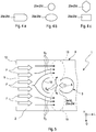
- FIG. 1 Illustrates a schematic representation of an example of an intake module 1 according to the invention with integrated exhaust gas recirculation.
- the intake module 1 comprises a housing 8 bounding a housing housing 8 made of a plastic.
- the housing 8 comprises a first housing wall 12 with at least one air inlet 9 and a second housing wall 13 with at least one fluid outlet 11.
- a virtual connecting line V between the at least one air inlet 9 and the at least one fluid outlet 11 defines a longitudinal direction L, which is a main flow direction which corresponds to the housing interior 4 fresh air F.
- the fresh air F can enter into the housing interior 4.
- a charge air cooler 15 is arranged, which is flowed through by the introduced into the housing interior 4 fresh air F.
- the fresh air F - which is typically compressed by an exhaust gas turbocharger, hot charge air - cooled by the charge air cooler 15.
- the intake module 1 further has a mixing chamber 2, which is part of the housing interior 4 and is limited by the intercooler 15 and the second housing wall 13.
- an exhaust gas distribution pipe 3 which extends along a transversely to the longitudinal direction L extending transverse direction Q of the housing 8 of the intake module 1.
- the exhaust gas distribution line 3 In the exhaust gas distribution line 3, at least one first and second exhaust gas outlet 5a, 5b are provided on a side of the exhaust gas distribution line 3 facing the air inlet 9, by means of which the exhaust gas A discharged from the internal combustion engine and flowing through the exhaust gas distribution line 3 flows into the mixing chamber 2 can be introduced.
- four such exhaust gas outlets 5a-5d are shown. Due to their high rigidity, a realization of the exhaust gas distribution line 3 in the form of an exhaust pipe is recommended. Of course, but deviating from such a design in the form of a tube, other suitable designs are also available.
- the longitudinal direction L can also be defined in other ways in variants of the example, for example by the main flow direction of the fresh air F in the mixing chamber 2, immediately before the fresh air F strikes the exhaust gas A introduced from the exhaust gas distribution line 3 into the mixing chamber 2.
- the intake module 1 comprises a provided on the exhaust gas distribution line 3 and in the manner of an opening 10 fluid passage 22. About this communicates an exhaust gas supply line 21 fluidly with the exhaust gas distribution line 3. About the exhaust gas supply line 21 is from the Internal combustion engine ejected and returned to this exhaust first introduced into the exhaust gas distribution line 3 and through this into the mixing chamber 2. Also, the exhaust gas supply line 21, analogous to the exhaust gas supply line 3, be designed as an exhaust pipe. In this case, said fluid passage 22 with respect to the transverse direction Q is arranged substantially centrally in the exhaust gas distribution line 3. Alternatively or additionally, the fluid passage 22 is also arranged substantially centrally in the mixing chamber 2 with respect to the transverse direction Q.
- exhaust gas A expelled from a combustion chamber of an internal combustion engine (not shown) is mixed with fresh air F drawn in from the environment U or with charge air charged, typically by an exhaust-gas turbocharger.
- the charge air or fresh air F is introduced via the air inlet 9 into the mixing chamber 2.
- the central longitudinal axis of the exhaust gas supply line 21 preferably extends in a plane E defined by the longitudinal direction L and a vertical direction H orthogonal to both the longitudinal and vertical directions L, Q. In the plane E is also the fluid passage 22.
- the exhaust gas supply line 21 thus also has a component in the high direction H.
- the exhaust gas supply line 21 extends from the plane of the FIG. 1 out. This clarifies, for example, the perspective view of the FIG. 6b , which will be explained in more detail below.
- the exhaust gas supply pipe 21 may also extend in a plane defined by the transverse direction Q and the high direction H in which the fluid passage 21 is disposed (not shown).
- FIG. 1 can a distance a 1 of the mixing chamber 2 in the transverse direction Q bounding the third housing wall 23 of the housing 8 to the exhaust gas supply line 21 in the transverse direction Q limiting and the third housing wall 23 facing the conduit wall 37a of the exhaust gas supply line 21 equal to a distance a 2 one of third housing wall 23 opposite, fourth housing wall 24 to one of the conduit wall 37 a opposite line side 37 b of the exhaust gas supply line 21 be.
- exhaust gas outlets 5a-5d are provided, which are arranged along the transverse direction Q at a distance from each other and the exhaust gas distribution line 3 fluidically with the mixing chamber 2 connect.
- the fluid passage 22 is arranged in the transverse direction Q between the exhaust gas outlets 5a, 5c and the exhaust gas outlets 5b, 5d.
- a different number of exhaust outlets 5a-5d can also be provided on the exhaust gas distribution line 3, a different number of exhaust outlets 5a-5d. It is conceivable, for example, to provide an even number of exhaust gas outlets 5a-5d and at least four such exhaust gas outlets a-5d.
- the arrangement of the outlets 5a-5d in the exhaust gas distribution line 3 can then take place such that, starting from the fluid passage 22 in and opposite to the transverse direction Q, the same number of exhaust gas outlets are respectively provided. In this way, the invention, symmetrical arrangement of the outlets 5a-5d is ensured relative to the fluid passage 22.
- FIG. 1 is defined by the longitudinal and the transverse direction L, Q is a cross-sectional plane of the intake module 1, in which the exhaust gas distribution line 3 and the exhaust gas supply line 21 to the exhaust gas supply line 21 symmetrical, in particular axisymmetric geometry.
- the exhaust gas distribution line 3 and the exhaust gas supply line 21 can be arranged symmetrically or axially symmetrically in the cross-sectional plane formed from the longitudinal and transverse directions L, Q, to an axis of symmetry S which runs along the longitudinal direction L and the exhaust gas Distribution line 3 with respect to the transverse direction Q centrally crosses.
- the symmetry axis S can also be defined by a virtual straight line (not shown) which runs parallel to the longitudinal direction and on which the fluid passage 22 is arranged.
- the exhaust gas distribution line 3 and the exhaust gas supply line 21 may have an inverted T-like geometry in said cross section.
- the number of fluid outlets 11 preferably corresponds to the number of cylinders of the internal combustion engine cooperating with the intake module 1 or is twice this number. That in the FIG. 1 As an example, intake module 1 with four fluid outlets 11 is designed for use with an internal combustion engine with four or eight cylinders.
- the realization of the intercooler unit 15 in the form of a coolant tube is particularly simple for a person skilled in the art.
- a coolant tube may have a respective coolant inlet or coolant outlet at the end.
- Technically more complex variants of the intercooler 15, however, may be designed as so-called tube bundle cooler or rib-tube cooler.
- Such a charge air cooler 15 may have a coolant path K, which in FIG. 1 is sketched only roughly schematic and for the cooling of the charge air cooler 15 by flowing fresh air F is flowed through by a coolant.
- the intercooler 15 may include a radiator housing 32 made of metal.
- the radiator housing 32 may include a housing wall 33 facing the exhaust gas distribution duct 3, in which, in the example of FIG.
- charge air outlets 38 are provided. After flowing through the intercooler 15 - this can be introduced into the housing interior 4 fresh air F through Ladelufteinlässe 36, which are provided in one of the housing wall 33 opposite housing wall 34 of the radiator housing 32 in the charge air cooler 15 - enters the fresh air F through the charge air outlets 38th again from the intercooler 15 and into the mixing chamber 2 a.
- the charge air cooler 15 may be provided with a coolant inlet 16 or coolant outlet 17 for introducing or discharging coolant into and out of the charge air cooler 15 with respect to the coolant path K on an end housing wall 35 outside the mixing chamber 2.
- FIG. 1 is the mixing chamber 2 between the charge air outlets 38 having housing wall 33 of the charge air cooler 15 and the second housing wall 13 of the housing 8 of the intake module 1, in which the fluid outlets 11 are arranged formed.
- the mixing chamber 2 results in the mixing chamber 2, a mixing section M within which the fresh air can mix with the exhaust gas A.
- the exhaust gas A flows in the direction of the charge air cooler 15, with the exhaust gas traversing a return flow path R.
- the mixing distance M is extended by the length of the return flow path R, whereby an improved mixing of the gases F, A is achieved.
- the guided through the intercooler 15 cooled fresh air has arranged in the intercooler 15 flow guides (not shown) at the exit from the charge air cooler 15 a very uniform, rectilinear flow.
- the exhaust flow directed countercurrently to the intercooler 15 reaches the intercooler 15 with an optimum design, without the exhaust gas A penetrating into the intercooler 15.
- the mixing section M on which there is a mixing of the fresh air F with the exhaust gas A, increased, resulting in improved mixing of the gases.
- a distance d 1 between the exhaust gas distribution line 3 and the intercooler 15 is selected such that the outflowing exhaust gas A just flows into the intercooler 15, but no longer penetrates into the intercooler 15.
- the introduced exhaust gas A sets the distance d 1 between the exhaust gas outlets 5a-5d and intercooler 15 twice, whereby the exhaust gas A already flows against the charge air flow when flowing against it and the mixing continues on the return flow up to the exhaust gas distribution line 3 ,
- the exhaust gas A continues to mix with the fresh air F, whereby a very homogeneous mixing is achieved before the gas mixture flows through the leading to the individual cylinder fluid outlets 11.
- an undesired contamination of the intercooler 15 is prevented and formed a maximum mixing distance with a homogeneous mixing of the gases.
- the distance d 1 between the exhaust gas distribution line 3 and the intercooler 15 about 2 cm to - 15 cm, preferably about 4 to 5 cm.
- the introduction of the exhaust gas A into the mixing chamber 2 of the intake module 1 takes place with a flow direction S A opposite to the flow direction S F fresh air F.
- This allows a comparison with conventional intake modules improved mixing of the exhaust A with fresh air F even in the smallest space.
- the fresh air F thus mixed with exhaust gas A can be homogeneously introduced into the internal combustion engine, which considerably improves its efficiency.
- FIG. 1 In order to achieve the greatest possible mixing of fresh air F and exhaust gas A, it is recommended accordingly FIG. 1 to place the exhaust gas distribution pipe 3 in the housing 8 so that the exhaust gas outlets 5a-5d face the air inlet 9. Then, the exhaust gas A emerging from the exhaust gas distribution line 3 flows as desired in a substantially opposite direction S A to the fresh air F into the mixing chamber 2, which favors a homogeneous mixing process of fresh air F and exhaust gas A.
- the flow direction S A runs opposite to the flow direction S F. Because a good mixing of fresh air F with exhaust gas A is just achieved when air and exhaust molecules under a Angles of as close as possible to 180 °. In this case, the two directions S A , S F form an angle of 180 ° to one another. Other preferred angle values for the angle between the flow directions S A , S F may be defined by an angular interval of 160 ° to 200 or of 170 ° to 190 °.
- the distance d 1 between the exhaust gas distribution line 3 and the charge air cooler 15 corresponds to a distance d 2 of the exhaust gas distribution line 3 to the second housing wall 13, in which the fluid outlets 11 are arranged to the cylinders (not shown).
- the mixing length in the mixing chamber 2 can be significantly extended.
- the distance d 1 between the exhaust gas distribution line 3 and the intercooler 15 can be greater (not shown) or, as in FIG. 1 shown, be smaller than the distance d 2 between the exhaust gas distribution line 3 and said second housing wall 13. According to the interpretation, such a multiplication, z. B. doubling or tripling, the mixing length can be achieved.
- intercooler 15 and exhaust gas distribution line 3 can be integrally formed on the housing 8 of the mixing chamber 3.
- intercooler 15 and exhaust distribution line 3 can also be screwed or welded to the housing 8.
- each exhaust gas outlet 5a-5d is provided in the exhaust gas distribution pipe 3.
- a number of exhaust gas outlet openings is provided, which is greater than the number of cylinders of the intake module 1 using the internal combustion engine.
- the number of exhaust gas outlets is preferably 5a-5d is a multiple of the number of cylinders or more.
- the use of eight, but also of 16 exhaust outlets is conceivable when the intake module 1 is used in a four-cylinder internal combustion engine.
- any number of exhaust gas outlet openings 5a-5d not individually assigned to the individual cylinders may also be provided.
- FIG. 2 shows the exhaust gas distribution line 3 in a separate representation.
- the exhaust gas outlets 5a-5d each include an exhaust gas outlet opening 25a-25d with an exhaust gas deflecting element 27a-27d projecting inwardly into the exhaust gas distribution pipe 3.
- the four exhaust baffles 27a-27d serve to deflect the exhaust gas flowing through the exhaust gas distribution pipe 3 to the exhaust gas outlet ports 25a-d associated therewith. In this way, an undesirable buildup of exhaust gas A at the two ends 26a, 26b of the exhaust gas distribution line 3 and an associated uneven distribution of the exhaust gas A to the individual exhaust gas outlets 5a-5d largely or even completely avoided.
- the exhaust gas deflecting elements 27a-27d shown can be dispensed with at individual exhaust gas outlets 5a-5d, in particular at the exhaust gas outlets 5a, 5d adjacent the two ends 26a, 26b of the exhaust gas distribution line 3 in the transverse direction Q (not shown).
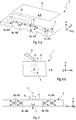
- FIG. 3b shows in addition to the presentation of FIG. 3a the exhaust gas distribution pipe 3 in a cross section of the exhaust gas distribution pipe 3 defined orthogonal to the transverse direction Q.
- the deflection element 27b has a first end section 29a, by means of which it is mounted on the first edge section 28a of the opening edge 28.
- a second, free end portion 29b of the exhaust gas deflector 27b opposite the first end portion 29a in cross section projects inwardly into the exhaust gas distribution pipe 3 and toward the exhaust gas supply pipe 21 from the opening edge 28.
- the exhaust deflectors 27 a - 27 d may be integrally formed on the exhaust gas distribution pipe 3.
- exhaust gas outlet openings 25a-25d With regard to the geometric configuration of the exhaust gas outlet openings 25a-25d, the person skilled in the art has various design options, which are shown by way of example in the rough-schematic representation of FIG FIG. 4 are shown. Exhaust gas outlet openings 25a-25d, which have approximately a round, in particular circular, or an elliptical opening contour, are particularly easy to realize in technical terms, cf. For this FIG. 4b , Alternatively, one is recommended in the Figure 4c shown realization with a polygonal opening contour, such as a rectangular and in particular a square opening contour. Also in the FIG. 4a shown combination of a rectangle and a semicircle is conceivable.
- FIG. 5 schematically illustrated attachment of a deflector 18 in the mixing chamber 2, in the flow direction S F of the fresh air F between the air inlet 9 and the exhaust gas distribution line 3, see this Fig. 1 .
- the placement of such a deflecting element 18, for example in the manner of a shield, may take place in such a way that it diverts at least part of the fresh air F introduced into the mixing chamber 3 before it strikes the exhaust gas A.
- the deflector 18 has in the in FIG. 5 shown longitudinal section of the exhaust pipe 3 along the transverse direction Q the shape of a circle segment and causes a deflection of the introduced into the mixing chamber 3 exhaust gas A.
- the fresh air F is channeled to edge regions of the housing 8 out.
- fresh air F and exhaust gas A have opposite directions of flow S F , S A when introduced into the mixing chamber 2, but not in the actual mixing in the mixing chamber 2 in the mixing chamber 2 due to the deflecting properties of the deflecting element 18 FIG. 5 with 19 designated area.
- the deflecting element 18 may generally have a geometry curved toward the respective exhaust gas outlet 5a-5d, for example circular segment-like geometry.
- FIG. 6a shows the intake module 1 according to the invention in a perspective view, the FIG. 6b in a longitudinal section along the longitudinal direction L of the intake module 1.
- a vertical direction H of the intake module is defined.
- the fluid passage 22 is on a the exhaust gas distribution line 3 in the vertical direction H limiting upper wall portion 6 of the exhaust gas distribution line 3 is provided.
- the exhaust gas supply line 21 may protrude at least in sections in the vertical direction H from the upper wall portion 6 of the exhaust gas distribution line 3.
- an additional exhaust gas outlet 7 may be provided in the exhaust gas distribution line 3 along the transverse direction Q in the area of the fluid passage 22 between the exhaust gas outlets 5a-5d.
Landscapes
- Engineering & Computer Science (AREA)
- Chemical & Material Sciences (AREA)
- Combustion & Propulsion (AREA)
- Mechanical Engineering (AREA)
- General Engineering & Computer Science (AREA)
- Physics & Mathematics (AREA)
- Thermal Sciences (AREA)
- Manufacturing & Machinery (AREA)
- Exhaust-Gas Circulating Devices (AREA)
Description
Die vorliegende Erfindung betrifft ein Ansaugmodul mit integrierter Abgasrückführung für eine Brennkraftmaschine.The present invention relates to an intake module with integrated exhaust gas recirculation for an internal combustion engine.
Ansaugmodule für Brennkraftmaschinen dienen zum Ansaugen und Einbringen von Luft aus der Umgebung in die Brennkammer der Brennkraftmaschine. Grundsätzlich können in solche Ansaugmodule ein oder mehrere Funktionselemente des Ansaugtrakts der Brennkraftmaschine integriert sein, um der Tatsache Rechnung zu tragen, dass in einem Kraftfahrzeug nur in begrenztem Maße Bauraum vorhanden ist. Bekannt sind Konzepte, bei denen eine sog. Abgasrückführung in das besagte Ansaugmodul integriert wird. Generell dient die Abgasrückführung zur Reduktion der von der Brennkraftmaschine betriebsmäßig in die Umgebung abgegebenen Schadstoffe und basiert auf der Idee, einen Teil des beim Verbrennungsvorgang erzeugten Abgases mit der vom Ansaugmodul angesaugten Frischluft zu vermischen und erneut in die Brennkammer einzubringen. Solche Abgasrückführungssysteme werden etwa in Verbindung mit einem Abgasturbolader ausgeführt. Der Stand der Technik umfasst sogenannte Hochdruck- oder Niederdruck-Rückführungssystemen, je nachdem, an welcher Stelle im Ansaug- bzw. Abgastrakt der Brennkraftmaschine die Abgasrückführung erfolgt.Intake modules for internal combustion engines are used for sucking and introducing air from the environment into the combustion chamber of the internal combustion engine. In principle, one or more functional elements of the intake tract of the internal combustion engine can be integrated into such intake modules in order to take account of the fact that there is only limited space available in a motor vehicle. Are known concepts in which a so-called. Exhaust gas recirculation is integrated into said intake module. In general, the exhaust gas recirculation serves to reduce the pollutants emitted by the internal combustion engine into the environment and is based on the idea of mixing a part of the exhaust gas produced in the combustion process with the fresh air sucked in by the intake module and reintroducing it into the combustion chamber. Such exhaust gas recirculation systems are carried out approximately in conjunction with an exhaust gas turbocharger. The prior art includes so-called high-pressure or low-pressure feedback systems, depending on where in the intake or exhaust gas of the engine exhaust gas recirculation takes place.
Als problematisch bei solchen Abgasrückführungssystemen erweist sich indes der im Kraftfahrzeug nur begrenzt zur Verfügung stehende Bauraum, welcher häufig einer optimalen Durchmischung des rückgeführten Abgases mit angesaugter Frischluft entgegensteht. Nur schwierig sicherzustellen ist vor diesem Hintergrund auch eine vorteilhafte, möglichst gleichmäßige Verteilung des rückzuführenden Abgases auf die verschiedenen Zylinder der Brennkraftmaschine. Denn in Ansaugmodulen mit konventioneller Leitungsgeometrie tritt oft die Situation auf, dass einzelne Zylinder aufgrund unterschiedlicher Leitungswege und Leitungs-Geometrien, die das rückzuführende Abgas beim Einleiten in die unterschiedlichen Zylinder zurücklegen muss, mit Abgas über- oder unterversorgt werden.As problematic in such exhaust gas recirculation systems, however, proves to be limited in the motor vehicle available space, which often precludes optimal mixing of the recirculated exhaust gas with fresh air sucked. It is difficult to ensure against this background that an advantageous, as even as possible distribution of the recirculated exhaust gas to the various cylinders of the internal combustion engine. For in intake modules with conventional line geometry, the situation often occurs that Individual cylinders are over- or undersupplied with exhaust due to different conduction paths and line geometries, which has to cover the recirculated exhaust gas when it is introduced into the different cylinders.
In diesem Zusammenhang offenbart die
Aus der
Die
Die
Hauptaufgabe der vorliegenden Erfindung ist die Bereitstellung einer verbesserten Ausführungsform eines Ansaugmoduls mit integrierter Abgasrückführung, welches insbesondere eine besonders gleichmäßige Durchmischung des rückzuführenden Abgases mit Frischluft gewährleistet, so dass eine Über- oder Unterversorgung einzelner Zylinder gegenüber den verbleibenden Zylindern mit rückzuführendem Abgas möglichst vermieden werden kann.The main object of the present invention is to provide an improved embodiment of an intake module with integrated exhaust gas recirculation, which in particular ensures a particularly uniform mixing of the exhaust gas to be recirculated with fresh air, so that over or under supply of individual cylinders with respect to the remaining cylinders with recirculating exhaust gas can be avoided as possible.
Diese Aufgabe wird durch den Gegenstand des unabhängigen Anspruchs 1 gelöst. Bevorzugte Ausführungsformen sind Gegenstand der abhängigen Patentansprüche.This object is solved by the subject matter of
Grundgedanke der Erfindung ist demnach, Abgas über eine im Wesentlichen symmetrisch realisierte Abgas-Zuführungsleitung in diese einzuleiten. Auf diese Weise stellen sich besonders gleichmäßige Druckverhältnisse ein, so dass sich auch eine vorteilhafte, vergleichmäßigte Einleitung des Abgases in die Durchmischungskammer ergibt.The basic idea of the invention is accordingly to introduce exhaust gas into the latter via a substantially symmetrically realized exhaust gas supply line. In this way, set up particularly uniform pressure conditions, so that there is also an advantageous, uniformed introduction of the exhaust gas into the mixing chamber.
Dieser Grundgedanke ist in einem erfindungsgemäßen Ansaugmodul realisiert. Dieses umfasst ein einen Gehäuseinnenraum begrenzendes Gehäuse, welches eine erste Gehäusewand mit wenigstens einem Lufteinlass und zweite Gehäusewand mit wenigstens einem Fluidauslass aufweist. Im Gehäuseinnenraum des Gehäuses ist ein Ladeluftkühler angeordnet. Im Gehäuse ist ferner eine Durchmischungskammer ausgebildet. Diese ist Teil des Gehäuseinnenraums und wird durch den Ladeluftkühler und die zweite Gehäusewand mit dem wenigstens einen Fluidauslass begrenzt. In der Durchmischungskammer ist eine Abgas-Verteilungsleitung angeordnet, welche sich entlang einer Querrichtung der Durchmischungskammer erstreckt. In der Abgas-Verteilungsleitung sind auf einer dem Lufteinlass zugewandten Seite der Abgas-Verteilungsleitung wenigstens ein erster und ein zweiter Abgasauslass vorgesehen, mittels welchen das aus der Brennkraftmaschine abgeführte und die Abgas-Verteilungsleitung durchströmende Abgas in die Durchmischungskammer einbringbar ist. Weiterhin umfasst das Ansaugmodul eine Abgas-Zuführungsleitung, die über einen an der Abgas-Verteilungsleitung vorgesehenen Fluiddurchlass fluidisch mit dieser kommuniziert. Erfindungsgemäß ist der Fluiddurchlass bezüglich der Querrichtung im Wesentlichen mittig in der Abgas-Verteilungsleitung und/oder in der Durchmischungskammer angeordnet. Eine derartige, mittige Anordnung des Fluiddurchlasses bewirkt, dass das über diesen Fluiddurchlass in die Abgas-Zuführungsleitung eingebrachte Abgas sich in beide Leitungsbereiche der Abgas-Zuführungsleitung verteilen kann, von wo aus es über Abgasauslässe in die Durchmischungskammer eingeleitet werden kann.This basic idea is realized in an intake module according to the invention. This comprises a casing housing bounding a housing, which has a first housing wall with at least one air inlet and second housing wall with at least one fluid outlet. In the housing interior of the housing, a charge air cooler is arranged. In the housing, a mixing chamber is further formed. This is part of the housing interior and is limited by the charge air cooler and the second housing wall with the at least one fluid outlet. In the mixing chamber, an exhaust gas distribution pipe is arranged, which extends along a transverse direction of the mixing chamber. In the exhaust gas distribution line, at least one first and one second exhaust gas outlet are provided on a side of the exhaust gas distribution line facing the air inlet, by means of which the one from the internal combustion engine discharged and flowing through the exhaust gas distribution line exhaust gas is introduced into the mixing chamber. Furthermore, the intake module comprises an exhaust gas supply line, which communicates fluidically with the latter via a fluid passage provided on the exhaust gas distribution line. According to the invention, the fluid passage is arranged substantially centrally in the exhaust gas distribution line and / or in the mixing chamber with respect to the transverse direction. Such a central arrangement of the fluid passage means that the exhaust gas introduced into the exhaust gas feed line via this fluid passage can be distributed in both conduit regions of the exhaust gas supply line, from where it can be introduced into the mixing chamber via exhaust gas outlets.
Erfindungsgemäß verläuft die Strömungsrichtung des in die Durchmischungskammer eingebrachten Abgases entgegengesetzt zur Strömungsrichtung der in die Durchmischungskammer eingebrachten Frischluft. Folglich bilden die beiden Richtungen einen Winkel von im Wesentlichen 180° zueinander aus. Unter "im Wesentlichen" ist dabei ein Winkelintervall von 160° bis 200, vorzugsweise von 170° bis 190° zu verstehen. Eine besonders gute Durchmischung der Frischluft mit Abgas wird jedoch gewährleistet, wenn Luft- und. Abgasmoleküle unter einem Winkel von möglichst genau 180° aufeinander treffen, denn in diesem Fall weisen die Luft- bzw. Abgasmoleküle beim Aufeinandertreffen einen zueinander entgegengesetzten Impuls auf, was deren Durchmischung besonders stark fördert. Weiterhin ist der Abstand zwischen Abgas-Verteilungsleitung und Frischluft an jeder Stelle gleich, wodurch sich eine, über den gesamten Querschnitt gleiche, Durchmischung einstellt.According to the invention, the flow direction of the exhaust gas introduced into the mixing chamber is opposite to the flow direction of the fresh air introduced into the mixing chamber. Consequently, the two directions form an angle of substantially 180 ° to each other. By "substantially" is meant an angular interval of 160 ° to 200, preferably 170 ° to 190 °. However, a particularly good mixing of the fresh air with exhaust gas is ensured when air and. Exhaust gas molecules meet at an angle of as close to 180 ° as possible, because in this case, the air or exhaust molecules have a mutually opposite impulse in the meeting, which promotes their mixing particularly strong. Furthermore, the distance between the exhaust gas distribution line and fresh air at each point is the same, resulting in one, over the entire cross-section same, mixing sets.
In einer bevorzugten Ausführungsform wird durch eine virtuelle Verbindungslinie zwischen dem wenigstens einen Lufteinlass und dem wenigstens einen Fluidauslass eine Längsrichtung definiert, die sich orthogonal zur Querrichtung erstreckt. Dabei erstreckt sich die Abgas-Zuführungsleitung zumindest abschnittsweise in einer Ebene, die durch die Längsrichtung und eine orthogonal sowohl zur Längsals auch Querrichtung erstreckende Hochrichtung definiert ist und in der auch der Fluiddurchlass angeordnet ist. Eine derartige Anordnung der Abgas-Zuführungsleitung führt zu einer vorteilhaften, besonders gleichmäßigen Einleitung von Abgas in die Durchmischungskammer erzielt. Alternativ dazu kann sich die Abgas-Zuführungsleitung auch in einer durch die Querrichtung und die Hochrichtung definierten Ebene, in welcher der Fluiddurchlass angeordnet ist, erstrecken.In a preferred embodiment, a longitudinal direction which extends orthogonal to the transverse direction is defined by a virtual connecting line between the at least one air inlet and the at least one fluid outlet. In this case, the exhaust gas supply line extends at least partially in a plane passing through the longitudinal direction and an orthogonal both to the longitudinal and Also transverse direction extending vertical direction is defined and in which also the fluid passage is arranged. Such an arrangement of the exhaust gas supply line leads to an advantageous, particularly uniform introduction of exhaust gas into the mixing chamber. Alternatively, the exhaust gas supply line may also extend in a plane defined by the transverse direction and the vertical direction in which the fluid passage is arranged.
Besagte Längsrichtung kann in Varianten auch auf andere Weise definiert sein, etwa durch eine Hauptströmungsrichtung der Frischluft in der Durchmischungskammer, unmittelbar bevor die Frischluft auf das aus der Abgas-Verteilungsleitung in die Durchmischungskammer eingeleitete Abgas trifft.Said longitudinal direction can also be defined in other ways, for example by a main flow direction of the fresh air in the mixing chamber, immediately before the fresh air strikes the exhaust gas introduced from the exhaust gas distribution line into the mixing chamber.
Bei einer vorteilhaften Ausgestaltung der Erfindung ist der Abstand zwischen der Abgas-Verteilungsleitung und dem Ladeluftkühler derart gewählt, dass das ausströmende Abgas den Ladeluftkühler gerade noch anströmt, jedoch nicht mehr in den Ladeluftkühler eindringt. Somit legt das eingeleitete Abgas die Distanzstrecke zwischen Abgaseinleitung und Ladeluftkühler zwei Mal zurück, wobei sich das Abgas beim Strömen entgegen der Ladeluftströmung bereits mit dieser vermischt und die Vermischung bei dem Zurückströmen bis zu der Abgas-Verteilungsleitung weiterschreitet. In dem Bereich nach der Abgas-Verteilungsleitung vermischt sich das Abgas weiterhin mit der Ladeluft, wodurch eine sehr homogene Durchmischung erreicht wird, bevor das Gasgemisch in die zu den einzelnen Zylinder führenden Auslässe eintritt. Somit wird eine Verunreinigung des Ladeluftkühlers verhindert und eine maximale Mischstrecke mit einer homogenen Durchmischung der Gase gebildet.In an advantageous embodiment of the invention, the distance between the exhaust gas distribution line and the intercooler is selected such that the outflowing exhaust gas just flows into the intercooler, but no longer penetrates into the intercooler. Thus, the introduced exhaust gas travels twice the distance between the exhaust gas inlet and intercooler, with the exhaust gas already mixing with it as it flows against the charge air flow and the mixing progressing as far back as the exhaust gas distribution line. In the area downstream of the exhaust gas distribution line, the exhaust gas continues to mix with the charge air, thereby achieving very homogeneous mixing before the gas mixture enters the outlets leading to the individual cylinders. Thus, contamination of the intercooler is prevented and formed a maximum mixing distance with a homogeneous mixing of the gases.
Gemäß einer besonderen Ausgestaltung der Erfindung entspricht der Abstand zwischen der Abgas-Verteilungsleitung und dem Ladeluftkühler dem Abstand der Abgas-Verteilungsleitung zu der zweiten Gehäusewand, in der die Fluidauslässe zu den Zylindern angeordnet sind. Durch eine solche Ausgestaltung kann die zur Verfügung stehende Mischlänge in der Durchmischungskammer verlängert werden.According to a particular embodiment of the invention, the distance between the exhaust gas distribution line and the intercooler corresponds to the distance of the exhaust gas distribution line to the second housing wall, in which the fluid outlets are arranged to the cylinders. By such an embodiment, the to Available mixing length can be extended in the mixing chamber.
Bei anderen Ausführungen kann der Abstand von der Abgas-Verteilungsleitung zum Ladeluftkühler größer oder kleiner sein als der Abstand zwischen der Abgas-Verteilungsleitung und besagter Gehäusewand. Entsprechend der Auslegung kann so eine Vervielfachung, z. B. Verdopplung oder Verdreifachung, der Mischlänge erreicht werden.In other embodiments, the distance from the exhaust gas distribution line to the charge air cooler may be greater or less than the distance between the exhaust gas distribution line and said housing wall. According to the interpretation, such a multiplication, z. B. doubling or tripling, the mixing length can be achieved.
Bei besonderen Ausgestaltungen beträgt der Abstand zwischen der Abgas-Verteilungsleitung und dem Ladeluftkühler ca. 2 - 15 cm, vorzugsweise ca. 4 - 5 cm.In particular embodiments, the distance between the exhaust gas distribution line and the charge air cooler is about 2 to 15 cm, preferably about 4 to 5 cm.
Für den Fachmann fertigungstechnisch besonders einfach gestaltet sich die Realisierung der Ladeluftkühlereinheit in Form eines Kühlmittelrohrs. Ein solches Kühlmittelrohr kann stirnseitig jeweils einen Kühlmitteleinlass bzw. Kühlmittelauslass aufweisen. Alternative Ladeluftkühler können als Rohrbündelkühler oder Rippe-Rohr-Kühler ausgebildet sein, in welchen jeweils wenigstens ein Kühlmittelpfad vorgesehen ist. Ein derartig ausgebildeter Ladeluftkühler kann an einer stirnseitigen Gehäusewand seines Kühlergehäuses einen Kühlmitteleinlass und einen Kühlmittelauslass aufweisen und bezüglich des Kühlmittelpfads im Wesentlichen parallel zur Abgas-Verteilungsleitung in der Durchmischungskammerangeordnet sein. In der Folge stellt sich eine besonders gleichmäßige Vermischung von Frischluft und Abgas in der Durchmischungskammer ein.The realization of the intercooler unit in the form of a coolant tube is particularly simple for a person skilled in the art. Such a coolant tube may have a respective coolant inlet or coolant outlet at the end. Alternative intercoolers may be designed as a tube-bundle cooler or rib-tube cooler, in each of which at least one coolant path is provided. Such a charge air cooler may have a coolant inlet and a coolant outlet on a front-side housing wall of its radiator housing and may be arranged with respect to the coolant path substantially parallel to the exhaust gas distribution line in the mixing chamber. As a result, a particularly uniform mixing of fresh air and exhaust gas sets in the mixing chamber.
In einer anderen bevorzugten Ausführungsform ist der Fluiddurchlass in Querrichtung zwischen dem ersten und dem zweiten Abgasauslass angeordnet ist. Dies fördert die Gleichverteilung des durch die Abgas-Verteilungsleitung strömenden Abgases auf die beiden Abgasauslässe.In another preferred embodiment, the fluid passage is disposed transversely between the first and second exhaust gas outlets. This promotes the uniform distribution of the exhaust gas flowing through the exhaust gas distribution line to the two exhaust gas outlets.
In einer besonders bevorzugten Ausführungsform umfasst die Abgas-Verteilungsleitung des erfindungsgemäßen Ansaugmoduls eine gerade Anzahl an Abgasauslässen, wobei wenigstens vier solcher Abgasauslässe vorgesehen sind. Besonders empfiehlt es sich, für jeden Zylinder der mit dem Ansaugmodul zusammenwirkenden Brennkraftmaschine genau einen Abgasauslass vorzusehen. In einem 4-Zylinder-Motor ist somit ein jeder der dann vier Abgasauslässe einem bestimmten Zylinder zugeordnet. Die Bereitstellung einer geraden Anzahl an Abgasauslässen gestattet es, den Fluiddurchlass - dem erfindungsgemäßen Gedanken folgend - symmetrisch zwischen den Abgasauslässen anzuordnen. Mit anderen Worten ausgehend vom Fluiddurchlass, durch welchen das Abgas in die Abgas-Verteilungsleitung eingebracht wird, kann dann in und entgegen der Querrichtung jeweils dieselbe Anzahl an Abgasauslässen vorgesehen werden.In a particularly preferred embodiment, the exhaust gas distribution line of the intake module according to the invention comprises an even number of exhaust gas outlets, wherein at least four such exhaust gas outlets are provided. It is particularly advisable to provide exactly one exhaust gas outlet for each cylinder of the engine interacting with the intake module. In a 4-cylinder engine, each of the four exhaust gas outlets is thus assigned to a specific cylinder. The provision of an even number of exhaust gas outlets makes it possible to arrange the fluid passage symmetrically between the exhaust gas outlets, following the idea according to the invention. In other words, starting from the fluid passage through which the exhaust gas is introduced into the exhaust gas distribution line, in each case the same number of exhaust gas outlets can be provided in and against the transverse direction.
Um möglichst identische Laufwege für das über den Fluiddurchlass in die Abgas-Verteilungsleitung eingetretene Abgas sicherzustellen, unabhängig davon, ob es durch den ersten oder den zweiten Abgasauslass in die Durchmischungskammer eintritt, wird in einer weiteren bevorzugten Ausführungsform vorgeschlagen, den Fluiddurchlass bezüglich der Querrichtung mittig in der Abgas-Verteilungsleitung anzuordnen.In order to ensure as identical paths as possible for the exhaust gas that has entered the exhaust gas distribution line via the fluid passage, regardless of whether it enters the mixing chamber through the first or the second exhaust gas outlet, in a further preferred embodiment, the fluid passage is centered in the transverse direction to arrange the exhaust distribution line.
In einer weiteren vorteilhaften Ausführungsform, in welcher der erfindungswesentliche und vorteilhafte Gedanke eines hochsymmetrischen Aufbaus weitergeführt wird, ist durch die Längs- und die Querrichtung eine Querschnittsebene des Ansaugmoduls definiert. Die Anordnung der Abgas-Verteilungsleitung und der Abgas-Zuführungsleitung zueinander sowie die Anordnung der beiden Leitungen relativ zur Durchmischungskammer erfolgt in diesem Szenario derart, dass die Abgas-Verteilungsleitung und die Abgas-Zuführungsleitung in diesem Querschnitt symmetrisch, insbesondere achsensymmetrisch, zu einer Symmetrieachse angeordnet sind, welche entlang der Längsrichtung verläuft und die Abgas-Verteilungsleitung bezüglich der Querrichtung mittig kreuzt.In a further advantageous embodiment, in which the idea of a highly symmetrical design essential to the invention is continued, a cross-sectional plane of the intake module is defined by the longitudinal and the transverse direction. The arrangement of the exhaust gas distribution line and the exhaust gas supply line to each other and the arrangement of the two lines relative to the mixing chamber in this scenario is such that the exhaust gas distribution line and the exhaust gas supply line in this cross section are arranged symmetrically, in particular axially symmetric, to an axis of symmetry which runs along the longitudinal direction and centrally crosses the exhaust gas distribution pipe with respect to the transverse direction.
Besonders zweckmäßig mögen die Abgas-Verteilungsleitung und die Abgas-Zuführungsleitung im Querschnitt des Ansaugmoduls derart zueinander angeordnet sein, dass im Zusammenspiel eine T-artige Geometrie gebildet wird.Particularly expedient like the exhaust gas distribution line and the exhaust gas supply line in cross section of the intake module may be arranged to each other such that a T-like geometry is formed in interaction.
Ein unerwünschtes Aufstauen von Abgases an den beiden Ende der Abgas-Verteilungsleitung lässt sich in einer bevorzugten Ausführungsform der Erfindung weitgehend oder gar vollständig unterbinden, indem wenigstens ein Abgasauslass als Abgas-Auslassöffnung ausgebildet wird, an welchem ein nach innen in die Abgas-Verteilungsleitung abstehendes Abgas-Ablenkelement vorgesehen ist. Dieses ist zum wenigstens teilweisen Ablenken des durch die Abgas-Verteilungsleitung strömenden Abgases zum jeweiligen Abgasauslass hin ausgebildet. Somit wird der das Abgas-Ablenkelement treffende Teil des die Abgas-Verteilungsleitung durchströmenden Abgas-Massenstroms durch Reflexion am Abgas-Abgaselement zum jeweiligen Abgasauslass hin abgelenkt. Im Ergebnis wird ein in etwa gleicher Massendurchsatz an Abgas durch die einzelnen Abgas-Auslässe hindurch erzielt.In one preferred embodiment of the invention, an undesired accumulation of exhaust gas at the two ends of the exhaust gas distribution line can be largely or completely prevented by forming at least one exhaust gas outlet as an exhaust gas outlet opening, on which an exhaust gas protruding inwardly into the exhaust gas distribution line -Blange element is provided. This is designed for at least partially deflecting the exhaust gas flowing through the exhaust gas distribution line to the respective exhaust gas outlet. Thus, the part of the exhaust gas mass flow flowing through the exhaust gas distribution line, which meets the exhaust gas deflection element, is deflected toward the respective exhaust gas outlet by reflection at the exhaust gas exhaust gas element. As a result, an approximately equal mass flow rate of exhaust gas is achieved through the individual exhaust gas outlets.
In einer vorteilhaften Weiterbildung kann jede Abgas-Auslassöffnung von einem von der der Abgas-Verteilungsleitung gebildeten Öffnungsrand eingefasst sein. Im Querschnitt des Ansaugmoduls besitzt besagter Öffnungsrand einen von der Abgas-Zuführungsleitung abgewandten ersten sowie einen der Abgas-Zuführungsleitung zugewandten zweiten Randabschnitt. Im selben Querschnitt weist das entsprechende Ablenkelement einen ersten Endabschnitt, mittels welchem es am ersten Randabschnitt abgebracht ist, und einen zweiten, freien Endabschnitt auf, welcher nach innen in die Abgas-Verteilungsleitung und zur Abgaszuführungsleitung hin vom Öffnungsrand absteht. Dies impliziert eine vorteilhafte, zur Abgas-Zuführungsleitung achsensymmetrische Anordnung der Abgas-Ablenkelemente derart, dass deren freies Ende zur Abgas-Zuführungsleitung weist.In an advantageous development, each exhaust gas outlet opening can be enclosed by an opening edge formed by the exhaust gas distribution line. In the cross section of the intake module has said opening edge facing away from the exhaust gas supply line first and one of the exhaust gas supply line facing the second edge portion. In the same cross section, the corresponding deflecting element has a first end portion, by means of which it is mounted on the first edge portion, and a second, free end portion, which projects inwardly into the exhaust gas distribution line and the exhaust gas supply line from the opening edge. This implies an advantageous, for the exhaust gas supply line axisymmetric arrangement of the exhaust gas deflector elements such that their free end faces the exhaust gas supply line.
Simulationsrechnungen haben gezeigt, dass eine besonders gleichmäßige Verteilung des durch die Abgas-Verteilungsleitung strömenden Abgases über die verschiedenen Abgasauslässe in die Durchmischungskammer genau dann erreicht wird, wenn im Querschnitt des Ansaugmoduls jedes Abgas-Ablenkelement mit einer die jeweilige Auslassöffnung definierende und die beiden Randabschnitte verbindenden virtuellen Verbindungsgeraden einen spitzen Winkel, vorzugsweise von 35° bis 55°, höchst vorzugsweise von 45°, ausbildet.Simulation calculations have shown that a particularly uniform distribution of the exhaust gas flowing through the exhaust gas distribution line through the different exhaust gas outlets into the mixing chamber is achieved exactly when in the cross section of the intake module each exhaust gas deflector element with a virtual defining the respective outlet opening and connecting the two edge sections Connecting straight line forms an acute angle, preferably from 35 ° to 55 °, most preferably from 45 °.
Technisch besonders einfach zu realisieren sind in diesem Zusammenhang Abgas-Auslassöffnungen, die etwa eine runde, insbesondere kreisrunde, eine elliptische, eine vieleckige, vorzugsweise eine rechteckige, höchst vorzugsweise eine quadratische, Öffnungskontur oder eine Kombination aus diesen Konturen, insbesondere eine Kombination aus einem Rechteck und einem Halbrund, aufweisen.In this connection, exhaust gas outlet openings which are approximately round, in particular circular, elliptical, polygonal, preferably rectangular, most preferably square, opening contours or a combination of these contours, in particular a combination of a rectangle, are particularly easy to realize in this context and a half round.
In einer anderen bevorzugten Ausführungsform ist durch eine orthogonal sowohl zur Längs- als auch zur Querrichtung verlaufende Richtung eine Hochrichtung des Ansaugmoduls definiert. In diesem Szenario ist der Fluiddurchlass auf einem die Abgas-Verteilungsleitung in Hochrichtung begrenzenden oberen Wandabschnitt der Abgas-Verteilungsleitung vorgesehen. Dies ermöglicht die Zuführung von Abgas über die Abgas-Zuführungsleitung von oben in die Abgas-Verteilungsleitung.In another preferred embodiment, a vertical direction of the suction module is defined by a direction orthogonal to both the longitudinal and the transverse direction. In this scenario, the fluid passage is provided on a top wall portion of the exhaust gas distribution piping defining the high-pressure exhaust gas distribution piping. This allows the supply of exhaust gas via the exhaust gas supply line from above into the exhaust gas distribution line.
Als aus fertigungstechnischer Sicht besonders vorteilhaft erweist sich eine Ausführungsform, bei welcher die Abgas-Zuführungsleitung zumindest abschnittsweise in der Hochrichtung vom oberen Wandabschnitt der Abgas-Verteilungsleitung absteht.As from a manufacturing point of view, an embodiment proves to be particularly advantageous in which the exhaust gas supply line protrudes at least in sections in the vertical direction from the upper wall portion of the exhaust gas distribution line.
Der für das erfindungsgemäße Ansaugmodul benötigte Bauraum lässt sich weiter verringern, wenn die Abgas-Verteilungsleitung als Abgasrohr mit einer Umfangswand ausgebildet wird, in welchem die Abgasauslässe und der Fluiddurchlass vorgesehen sind. Darüber hinaus ergeben sich bei einer solchen, rohrartigen Realisierung auch beträchtliche Kostenvorteile bei der Herstellung.The space required for the intake module according to the invention can be further reduced if the exhaust gas distribution line is formed as an exhaust pipe with a peripheral wall, in which the exhaust gas outlets and the fluid passage are provided. In addition, in such a tubular realization also considerable cost advantages in the production.
In einer besonders bevorzugten Ausführungsform kann - zur verbesserten Gleichverteilung des Abgases mit Frischluft - in der Abgas-Verteilungsleitung entlang der Querrichtung auf Höhe des Fluiddurchlasses ein zusätzlicher Abgasauslass vorgesehen werden.In a particularly preferred embodiment, for the improved uniform distribution of the exhaust gas with fresh air, an additional exhaust gas outlet can be provided in the exhaust gas distribution line along the transverse direction at the level of the fluid passage.
Um in den oben beschriebenen Szenarien die Durchmischung von Frischluft und Abgas weiter zu verbessern, empfiehlt sich die Anbringung von wenigstens einem Ablenkelement in der Durchmischungskammer, und zwar bzgl. der Strömungsrichtung der Frischluft zwischen Lufteinlass und Abgas-Verteilungsleitung. Die Platzierung eines solchen Ablenkelements, beispielsweise in der Art eines Schildes, sollte derart erfolgen, dass es wenigstens einen Teil der in die Durchmischungskammer eingebrachten Luft ablenkt, bevor sie auf das in die Durchmischungskammer eingebrachte Abgas trifft. Hinsichtlich des Durchmischungsprozesses lassen sich besonders gute Ergebnisse erzielen, wenn das besagte Ablenkelement gleichzeitig eine Ablenkung des Abgases bewirkt, bevor dieses auf die Frischluft trifft. Besonders zweckmäßig bietet es sich an, das Ablenkelement so auszugestalten, dass es die in die Durchmischungskammer eingeleitete Frischluft kanalisiert, bevor diese mit Abgas vermischt wird.In order to further improve the mixing of fresh air and exhaust gas in the scenarios described above, the attachment of at least one deflecting element in the mixing chamber is advisable, with respect to the flow direction of the fresh air between the air inlet and exhaust gas distribution line. Placement of such a deflector, such as a shield, should be such as to deflect at least a portion of the air introduced into the mixing chamber prior to impacting the exhaust gas introduced into the mixing chamber. With regard to the mixing process, particularly good results can be achieved if the said deflecting element at the same time effects a deflection of the exhaust gas before it impinges on the fresh air. It is particularly expedient to design the deflection element in such a way that it channels the fresh air introduced into the mixing chamber before it is mixed with exhaust gas.
Bei einer vorteilhaften Weiterbildung sind der Lufteinlass und der Abgasauslass im Querschnitt des Ansaugmoduls einander zugewandt. Im Querschnitt des Ansaugmoduls kann das das Ablenkelement eine zum Luftauslass hin gekrümmte, vorzugsweise kreissegmentartige, Geometrie aufweisen. Dies bewirkt die gewünschte Kanalisierung der Strömungsrichtung des in die Durchmischungskammer eingebrachten Abgases, bevor es auf Frischluft trifft. In diesem Szenario besitzen Frischluft und Abgas zwar beim Einleiten in die Durchmischungskammer im Wesentlichen entgegengesetzte Strömungsrichtungen, nicht jedoch beim eigentlichen Aufeinandertreffen von Abgas- und Frischluftmolekülen in der Durchmischungskammer. Die störende Ausbildung von Wirbelströmungen, die den Luft- bzw. Abgasmassendurchsatz durch das Saugmodul unerwünschterweise zu verringern vermögen, wird auf diese Weise weitgehend ausgeschlossen.In an advantageous development, the air inlet and the exhaust gas outlet in the cross section of the intake module facing each other. In the cross section of the intake module, the deflecting element may have a geometry which is curved toward the air outlet and preferably has a circular segment. This causes the desired channeling of the flow direction of the introduced into the mixing chamber exhaust gas before it encounters fresh air. In this scenario, fresh air and exhaust gas, while being introduced into the mixing chamber, have substantially opposite flow directions, but not the actual one Clash of exhaust and fresh air molecules in the mixing chamber. The disturbing formation of turbulent flows, which are able undesirably to reduce the air or exhaust gas mass flow rate through the suction module, is largely excluded in this way.
In einer weiteren bevorzugten Ausführungsform weist die Durchmischungskammer ein Gehäuse auf, in welchem der Lufteinlass vorgesehen ist. Der Lufteinlass ist dabei vorzugsweise derart an einer ersten Gehäusewand des Gehäuses angeordnet, so dass dieser wenigstens einem Fluidauslass gegenüberliegt, welcher entsprechend an einer zweiten Gehäusewand vorgesehen ist. Typischerweise ist am Gehäuse nicht nur ein einziger solcher Fluidauslass vorhanden; vorzugsweise ist vielmehr eine Mehrzahl von Fluidauslässen vorgesehen, welche einer Anzahl an Zylindern der das Ansaugmodul verwendenden Brennkraftmaschine entspricht, so dass also jeder Fluidauslass einem bestimmten Zylinder der Brennkraftmaschine zugeordnet ist. Besonders bevorzugt sind jedem Zylinder genau zwei solche Fluidauslasse zugeordnet, d.h. die Anzahl an Fluidauslässen beträgt das Zweifache der Zylinderzahl. Der Lufteinlass und der wenigstens eine Fluidauslass können sich entlang der Längsrichtung gegenüberliegen.In a further preferred embodiment, the mixing chamber has a housing in which the air inlet is provided. The air inlet is preferably arranged on a first housing wall of the housing, so that it faces at least one fluid outlet, which is provided correspondingly on a second housing wall. Typically, not only a single such fluid outlet is present on the housing; Rather, a plurality of fluid outlets is preferably provided which corresponds to a number of cylinders of the internal combustion engine using the intake module, so that therefore each fluid outlet is assigned to a specific cylinder of the internal combustion engine. More preferably, exactly two such fluid outlets are associated with each cylinder, i. the number of fluid outlets is twice the number of cylinders. The air inlet and the at least one fluid outlet may face each other along the longitudinal direction.
Die Erfindung betrifft ferner eine Brennkraftmaschine mit wenigstens zwei Zylindern sowie mit einem mit den Zylindern zusammenwirkenden Ansaugmodul mit einem oder mehreren der vorangehend genannten Merkmale.The invention further relates to an internal combustion engine with at least two cylinders and with a cooperating with the cylinders intake module with one or more of the aforementioned features.
Als bevorzugt mag eine Ausführungsform erachtet werden, bei welcher die Anzahl an Zylindern der Anzahl an Abgasauslässen entspricht, so dass jedem Zylinder genau ein Abgasauslass zugeordnet ist.As preferred may be considered an embodiment in which the number of cylinders corresponds to the number of exhaust outlets, so that each cylinder is associated with exactly one exhaust outlet.
Die Erfindung betrifft schließlich Kraftfahrzeug mit einer Fahrzeugkarosserie sowie mit einer Brennkraftmaschine mit einem oder mehreren der vorangehend genannten Merkmale.Finally, the invention relates to motor vehicles with a vehicle body and with an internal combustion engine having one or more of the aforementioned features.
Weitere wichtige Merkmale und Vorteile der Erfindung ergeben sich aus den Unteransprüchen, aus den Zeichnungen und aus der zugehörigen Figurenbeschreibung anhand der Zeichnungen.Other important features and advantages of the invention will become apparent from the dependent claims, from the drawings and from the associated figure description with reference to the drawings.
Es versteht sich, dass die vorstehend genannten und die nachstehend noch zu erläuternden Merkmale nicht nur in der jeweils angegebenen Kombination, sondern auch in anderen Kombinationen oder in Alleinstellung verwendbar sind, ohne den Rahmen der vorliegenden Erfindung zu verlassen.It is understood that the features mentioned above and those yet to be explained below can be used not only in the particular combination given, but also in other combinations or in isolation, without departing from the scope of the present invention.
Bevorzugte Ausführungsbeispiele der Erfindung sind in den Zeichnungen dargestellt und werden in der nachfolgenden Beschreibung näher erläutert, wobei sich gleiche Bezugszeichen auf gleiche oder ähnliche oder funktional gleiche Komponenten beziehen.Preferred embodiments of the invention are illustrated in the drawings and will be described in more detail in the following description, wherein like reference numerals refer to the same or similar or functionally identical components.
Es zeigen, jeweils schematisch
- Fig. 1
- ein Beispiel eines erfindungsgemäßen Ansaugmoduls,
- Fig. 2
- eine Detaildarstellung der Abgas-Verteilungsleitung des Ansaugmoduls der
Figur 1 , - Fig. 3a/b
- eine Detaildarstellung der Abgas-
Verteilungsleitung der Figur 2 im Bereich eines Abgasauslasses, - Fig. 4a-c
- Beispiele für eine mögliche geometrische Formen einer Abgas-Auslassöffnung,
- Fig. 5
- eine Variante des Beispiels der
Figur 1 mit einem Ablenkelement zum Ablenken von in die Durchmischungskammer eingebrachtem Abgas, - Fig. 6a/b
- das Ansaugmodul der
Figur 1 in einer perspektivischen Ansicht bzw. in einem orthogonal zur Querrichtung Q verlaufenden Schnitt desAnsaugmoduls 1, - Fig. 7
- eine Draufsicht auf die Abgas-Verteilungsleitung entlang der Längsrichtung des Ansaugmoduls.
- Fig. 1
- an example of a suction module according to the invention,
- Fig. 2
- a detailed view of the exhaust distribution line of the intake module of
FIG. 1 . - Fig. 3a / b
- a detailed representation of the exhaust gas distribution line of
FIG. 2 in the area of an exhaust outlet, - Fig. 4a-c
- Examples of possible geometric shapes of an exhaust gas outlet opening,
- Fig. 5
- a variant of the example of
FIG. 1 with a deflector for deflecting introduced into the mixing chamber exhaust, - Fig. 6a / b
- the intake module of
FIG. 1 in a perspective view or in a direction orthogonal to the transverse direction Q extending section of theintake module 1, - Fig. 7
- a plan view of the exhaust distribution line along the longitudinal direction of the intake module.
Über den Lufteinlass 9 kann die Frischluft F in den Gehäuseinnenraum 4 eintreten. Im Gehäuseinnenraum 4 ist ein Ladeluftkühler 15 angeordnet, welcher von der in den Gehäuseinnenraum 4 eingeleiteten Frischluft F durchströmt wird. Auf diese Weise wird die Frischluft F - bei dieser handelt es sich typischerweise um von einem Abgasturbolader komprimierte, heiße Ladeluft - vom Ladeluftkühler 15 gekühlt.Via the
Das Ansaugmodul 1 besitzt ferner eine Durchmischungskammer 2, die Teil des Gehäuseinnenraums 4 ist und durch den Ladeluftkühler 15 und die zweite Gehäusewand 13 begrenzt wird. In der Durchmischungskammer 2 ist eine Abgas-Verteilungsleitung 3 angeordnet, welche sich entlang einer quer zur Längsrichtung L verlaufenden Querrichtung Q des Gehäuses 8 des Ansaugmoduls 1 erstreckt. In der Abgas-Verteilungsleitung 3 sind auf einer dem Lufteinlass 9 zugewandten Seite der Abgas-Verteilungsleitung 3 wenigstens ein erster und ein zweiter Abgasauslass 5a, 5b vorgesehen, mittels welchen das aus der Brennkraftmaschine abgeführte und die Abgas-Verteilungsleitung 3 durchströmende Abgas A in die Durchmischungskammer 2 einbringbar ist. Im Beispiel der
Die Längsrichtung L kann in Varianten des Beispiels auch auf andere Weise definiert sein, etwa durch die Hauptströmungsrichtung der Frischluft F in der Durchmischungskammer 2, unmittelbar bevor die Frischluft F auf das aus der Abgas-Verteilungsleitung 3 in die Durchmischungskammer 2 eingeleitete Abgas A trifft.The longitudinal direction L can also be defined in other ways in variants of the example, for example by the main flow direction of the fresh air F in the mixing
Weiterhin umfasst das Ansaugmodul 1 einen an der Abgas-Verteilungsleitung 3 vorgesehenen und in der Art eines Durchbruchs 10 ausgebildeten Fluiddurchlass 22. Über diesen kommuniziert eine Abgas-Zuführungsleitung 21 fluidisch mit der Abgas-Verteilungsleitung 3. Über die Abgas-Zuführungsleitung 21 wird das aus der Brennkraftmaschine ausgestoßene und wieder in diese rückzuführende Abgas zunächst in die Abgas-Verteilungsleitung 3 und über diese in die Durchmischungskammer 2 eingeleitet. Auch die Abgas-Zuführungsleitung 21 kann, analog zur Abgas-Zuführungsleitung 3, als Abgasrohr ausgebildet sein. Dabei ist besagter Fluiddurchlass 22 bezüglich der Querrichtung Q im Wesentlichen mittig in der Abgas-Verteilungsleitung 3 angeordnet. Alternativ oder zusätzlich ist der Fluiddurchlass 22 bezüglich der Querrichtung Q auch im Wesentlichen mittig in der Durchmischungskammer 2 angeordnet.Furthermore, the
In der Durchmischungskammer 2 des Ansaugmoduls 1 wird aus einer Brennkammer einer Brennkraftmaschine (nicht gezeigt) ausgestoßenes Abgas A zur Rückführung in die Brennkammer mit aus der Umgebung U angesaugter Frischluft F bzw. mit - typischerweise durch einen Abgasturbolader - aufgeladener Ladeluft durchmischt. Die Ladeluft bzw. Frischluft F wird dabei über den Lufteinlass 9 in die Durchmischungskammer 2 eingebracht.In the mixing
Die Mittellängsachse der Abgas-Zuführungsleitung 21 erstreckt sich vorzugsweise in einer Ebene E, die durch die Längsrichtung L und eine orthogonal sowohl zur Längs- als auch Hochrichtung L, Q erstreckende Hochrichtung H definiert ist. In der Ebene E liegt auch der Fluiddurchlass 22. Die Abgas-Zuführungsleitung 21 besitzt also auch eine Komponente in Hochrichtung H. Mit anderen Worten, die Abgas-Zuführungsleitung 21 erstreckt sich aus der Zeichenebene der
Entsprechend
In der Abgas-Verteilungsleitung 3 sind, wie bereits erläutert, vier Abgasauslässe 5a-5d vorgesehen, die entlang der Querrichtung Q im Abstand zueinander angeordnet sind und die Abgas-Verteilungsleitung 3 fluidisch mit der Durchmischungskammer 2 verbinden. Der Fluiddurchlass 22 ist in Querrichtung Q zwischen den Abgasauslässen 5a, 5c und den Abgasauslässen 5b, 5d angeordnet. In Varianten des Beispiels der
Entsprechend der
Typischerweise ist am Gehäuse 8 nicht nur ein einziger Fluidauslass 11 vorgesehen. Vielmehr entspricht die Anzahl an Fluidauslässen 11 bevorzugt der Anzahl an Zylindern der mit dem Ansaugmodul 1 zusammenwirkenden Brennkraftmaschine oder beträgt ein Zweifaches dieser Anzahl. Das in der
Für den Fachmann fertigungstechnisch besonders einfach gestaltet sich die Realisierung der Ladeluftkühlereinheit 15 in Form eines Kühlmittelrohrs. Ein solches Kühlmittelrohr kann stirnseitig jeweils einen Kühlmitteleinlass bzw. Kühlmittelauslass aufweisen. Technisch komplexere Varianten des Ladeluftkühlers 15 können hingegen als sogenannte Rohrbündelkühler oder Rippe-Rohr-Kühler ausgebildet sein. Ein solcher Ladeluftkühler 15 kann einen Kühlmittelpfad K aufweisen, der in
Um eine besonders gleichmäßige Vermischung der Frischluft F mit dem Abgas A zu erreichen, bietet es sich an, den Ladeluftkühler 15 bezüglich der Erstreckung des Kühlmittelpfads K im Wesentlichen parallel, also entlang der Querrichtung Q, zur Abgas-Zuführungsleitung 3 im Gehäuseinnenraum 4 anzuordnen. Entsprechend
Die durch den Ladeluftkühler 15 hindurchgeführte gekühlte Frischluft weist durch in dem Ladeluftkühler 15 angeordnete Strömungsführungen (nicht gezeigt) beim Austritt aus dem Ladeluftkühler 15 eine sehr gleichmäßige, geradlinig gerichtete Strömung auf. Die im Gegenstrom auf den Ladeluftkühler 15 gerichtete Abgasströmung erreicht bei optimaler Auslegung den Ladeluftkühler 15, ohne dass das Abgas A in den Ladeluftkühler 15 eindringt. Somit ist ein unerwünschtes Verschmutzen des Ladeluftkühlers 15 verhindert. Weiterhin ist die Mischstrecke M, auf welcher eine Durchmischung der Frischluft F mit dem Abgas A erfolgt, vergrößert, was zu einer verbesserten Durchmischung der Gase führt.The guided through the
Im Beispiel der
Bei besonderen Ausgestaltungen beträgt der Abstand d1 zwischen der Abgas-Verteilungsleitung 3 und dem Ladeluftkühler 15 ca. 2cm bis - 15 cm, vorzugsweise ca. 4 bis 5 cm.In particular embodiments, the distance d 1 between the exhaust
Die Einleitung des Abgases A in die Durchmischungskammer 2 des Ansaugmoduls 1 erfolgt mit einer Strömungsrichtung SA entgegengesetzt zur Strömungsrichtung SF der Frischluft F. Dies gestattet eine gegenüber herkömmlichen Ansaugmodulen verbesserte Durchmischung des Abgases A mit Frischluft F auch auf engstem Bauraum. Somit lässt sich die derart mit Abgas A durchmischte Frischluft F homogen in die Brennkraftmaschine einbringen, was deren Wirkungsgrad erheblich verbessert.The introduction of the exhaust gas A into the mixing
Um eine möglichst ausgeprägte Durchmischung von Frischluft F und Abgas A zu erzielen, empfiehlt es sich entsprechend
Wie in
Vorzugsweise entspricht der Abstand d1 zwischen der Abgas-Verteilungsleitung 3 und dem Ladeluftkühler 15 einem Abstand d2 der Abgas-Verteilungsleitung 3 zur zweiten Gehäusewand 13, in der die Fluidauslässe 11 zu den Zylindern angeordnet sind (nicht gezeigt). Durch eine solche Ausgestaltung kann die Mischlänge in der Durchmischungskammer 2 wesentlich verlängert werden.Preferably, the distance d 1 between the exhaust
In dazu alternativen Varianten des Beispiels kann der Abstand d1 zwischen der Abgas-Verteilungsleitung 3 und dem Ladeluftkühler 15 größer (nicht gezeigt) oder, wie in
Zum Zwecke einer kostengünstigen Fertigung des erfindungsgemäßen Ansaugmoduls 1 können Ladeluftkühler 15 und Abgas-Verteilungsleitung 3 integral am Gehäuse 8 der Durchmischungskammer 3 ausgeformt werden. Alternativ dazu können Ladeluftkühler 15 und Abgas-Verteilungsleitung 3 aber auch mit dem Gehäuse 8 verschraubt oder verschweißt werden.For the purpose of cost-effective production of the
Im Beispiel der
In Varianten des Beispiels kann an einzelnen Abgasauslässen 5a-5d, insbesondere an den den beiden Enden 26a, 26b der Abgas-Verteilungsleitung 3 in Querrichtung Q benachbarten Abgasauslässen 5a, 5d auf die gezeigten Abgas-Ablenkelemente 27a-27d verzichtet werden (nicht gezeigt).In variants of the example, the exhaust
Jede Abgas-Auslassöffnung 25a-25d wird von einem durch die Abgas-Verteilungsleitung 3 gebildeten Öffnungsrand 28 eingefasst, was im Folgenden anhand der
In dem in
Die Abgas-Ablenkelemente 27a-27d können integral an der Abgas-Verteilungsleitung 3 ausgeformt sein.The
Hinsichtlich der geometrischen Ausgestaltung der Abgas-Auslassöffnungen 25a-25d bieten sich dem Fachmann verschiedene konstruktive Optionen, die exemplarisch in der grobschematischen Darstellung der
Um die vorliegend erläuterte Durchmischung von Frischluft F und Abgas A weiter zu verbessern, empfiehlt sich die in
Das Ablenkelement 18 weist in dem in
Entsprechend
Die
Optional kann in der Abgas-Verteilungsleitung 3 entlang der Querrichtung Q im Bereich des Fluiddurchlasses 22 zwischen den Abgasauslässen 5a-5d ein zusätzlicher Abgasauslass 7 vorgesehen sein. Dies illustriert die Darstellung der
Claims (11)
- Intake (1) with integrated exhaust gas recirculation,- with a housing (8) limiting a housing interior (4), which has one first housing wall (12) with at least one air inlet (9) and one second housing wall (13) with at least one fluid outlet (11),- with an intercooler (15) disposed in the housing interior (4),- with an intermixing chamber (2) which is part of the housing interior (4) and is limited by the intercooler (15) and the second housing wall (13),- with an exhaust gas distribution line (3) disposed in the intermixing chamber (2), extending along a perpendicular direction (Q), wherein in the exhaust gas distribution line (3) on a side of the exhaust gas distribution line (3) facing the air inlet (9) are provided at least one first and one second exhaust gas outlet (5a-5d) by means of which the exhaust gas (A) drawn out of the internal combustion machine and flowing through the exhaust gas distribution line (3) can be brought into the intermixing chamber (2),- with an exhaust gas supply line (21) fluidically connected with the exhaust gas distribution line (3) via a fluid passage (22) provided at same,
characterised in that- the fluid passage (22) is disposed with respect to the perpendicular direction (Q) substantially centrally in the exhaust gas distribution line (3) and/or in the intermixing chamber (2),- the intercooler (15) and the exhaust gas distribution line (3) are disposed in the housing (8) such that the flow direction (SA) of the exhaust gas (A) introduced into the intermixing chamber (2) runs substantially in the opposite direction to the flow direction (SF) of the fresh air (F) introduced into the intermixing chamber (2), so that the two directions (SA, SF) form an angle of substantially 180 ° to one another. - Intake module according to claim 1,
characterised in that- a longitudinal direction (L) is defined by a virtual connection line between the at least one air inlet (9) and the at least one fluid outlet (11), wherein the perpendicular direction (Q) extends orthogonally to the longitudinal direction (L),- either the exhaust gas supply line (21) extends in a plane (E) which is defined by the longitudinal direction (L) and a height direction (H) extending orthogonally both in relation to the longitudinal direction and in relation to the perpendicular direction (L, Q) and in which the fluid passage (22) is disposed, or the exhaust gas supply line (21) extends in a plane defined by the perpendicular direction (Q) and the height direction (H) in which the fluid passage (22) is disposed. - Intake module according to claim 1 or 2,
the intercooler (15) and the exhaust gas distribution line (3) are disposed in the housing (8) such that the exhaust gas (A) introduced into the intermixing chamber (2) for the time being does not enter into the intercooler (15). - Intake module according to one of the preceding claims,
characterised in that
a distance (d1) between the exhaust gas distribution line (3) and the intercooler (15) is substantially equal to the one distance (d2) between the exhaust gas distribution line (3) and the second housing wall (3) or is larger or smaller than this distance (d2). - Intake module according to one of the preceding claims,
characterised in that
the intercooler (15) is formed as a tube bundle cooler or as rib tube cooler with at least one coolant path (K), which has at a face-side housing wall (23) a coolant inlet (16) and a coolant outlet (17) and with respect to the coolant path (K) is disposed substantially parallel to the exhaust gas distribution line (3) in the intermixing chamber (2). - Intake module according to one of the preceding claims,
characterised in that
the fluid passage (22) is disposed in perpendicular direction (Q) between the first and the second exhaust gas outlets (5a, 5b). - Intake module according to one of the preceding claims,
characterised in that
an even number of exhaust gas outlets (5a-5d) and at least four such exhaust gas outlets (5a-5d) are provided in the exhaust gas distribution line (3), wherein in the exhaust gas distribution line starting from the fluid passage (21) and against the perpendicular direction (Q) is provided in each case the same number of exhaust gas outlets (5a-5d). - Intake module according to one of the preceding claims,
characterised in that- by the longitudinal direction and the perpendicular direction (L, Q) is defined a cross-section of the intake module (1),- the exhaust gas distribution line (3) and the exhaust gas supply line (21) and the exhaust gas outlets (5a-5d) in this cross-section are disposed symmetrically, in particular axially symmetrically, to a symmetry axis, which extends along the longitudinal direction (L) and crosses the exhaust gas distribution line (3) with respect to the perpendicular direction (Q). - Intake module according to one of the preceding claims,
characterised in that
the fluid passage (22) is provided on an upper wall section (6) of the exhaust gas distribution line (3) limiting the exhaust gas distribution line (3) in the height direction (H). - Intake module according to claim 9,
characterised in that
the exhaust gas supply line (21) projects at least sectionally in the height direction (H) from the upper wall section (6) of the exhaust gas distribution line (3). - Intake module according to one of the preceding claims,
characterised in that
in the exhaust gas distribution line (3) along the perpendicular direction (Q) is provided at the level of the fluid passage an additional exhaust gas outlet (7).
Applications Claiming Priority (2)
| Application Number | Priority Date | Filing Date | Title |
|---|---|---|---|
| DE102014214591.0A DE102014214591A1 (en) | 2014-07-24 | 2014-07-24 | Intake module with integrated exhaust gas recirculation for an internal combustion engine |
| PCT/EP2015/061965 WO2016012129A1 (en) | 2014-07-24 | 2015-05-29 | Intake module having integrated exhaust gas recirculation for an internal combustion engine |
Publications (2)
| Publication Number | Publication Date |
|---|---|
| EP3172425A1 EP3172425A1 (en) | 2017-05-31 |
| EP3172425B1 true EP3172425B1 (en) | 2018-10-17 |
Family
ID=53200014
Family Applications (1)
| Application Number | Title | Priority Date | Filing Date |
|---|---|---|---|
| EP15723982.3A Not-in-force EP3172425B1 (en) | 2014-07-24 | 2015-05-29 | Intake module having integrated exhaust gas recirculation for an internal combustion engine |
Country Status (3)
| Country | Link |
|---|---|
| EP (1) | EP3172425B1 (en) |
| DE (1) | DE102014214591A1 (en) |
| WO (1) | WO2016012129A1 (en) |
Families Citing this family (2)
| Publication number | Priority date | Publication date | Assignee | Title |
|---|---|---|---|---|
| JP6677202B2 (en) * | 2017-03-28 | 2020-04-08 | トヨタ自動車株式会社 | Intake manifold |
| CN118959188A (en) * | 2024-10-17 | 2024-11-15 | 湖南敏行汽车科技有限公司 | Engine air intake structure |
Family Cites Families (16)
| Publication number | Priority date | Publication date | Assignee | Title |
|---|---|---|---|---|
| JPS57171058A (en) * | 1981-04-11 | 1982-10-21 | Nissan Motor Co Ltd | Distributing device for exhaust gas recirculation system |
| JPS5915976U (en) * | 1982-07-22 | 1984-01-31 | 住友金属工業株式会社 | Grounding detection device for magnetic particle detector |
| US5957116A (en) | 1997-08-28 | 1999-09-28 | Cummins Engine Company, Inc. | Integrated and separable EGR distribution manifold |
| DE10004552A1 (en) | 2000-02-02 | 2001-08-09 | Mann & Hummel Filter | Intake pipe with integrated exhaust gas recirculation |
| JP2003262164A (en) * | 2002-03-07 | 2003-09-19 | Denso Corp | Intake device for internal combustion engine |
| DE10354129A1 (en) | 2003-11-19 | 2005-06-23 | Mahle Filtersysteme Gmbh | Intake system for an internal combustion engine |
| DE102006048485A1 (en) * | 2006-10-11 | 2008-04-17 | Behr Gmbh & Co. Kg | Charge air cooling device for an internal combustion engine, system with a charge air cooling device |
| DE102007009354A1 (en) * | 2007-02-23 | 2008-09-04 | Mahle International Gmbh | Fresh gas module for a fresh gas system |
| DE102007035556A1 (en) * | 2007-07-28 | 2009-01-29 | Daimler Ag | Mixing apparatus for adding exhaust gas recirculation flow into charge air flow of internal-combustion engine, has connecting tube running transverse through passage channel and connecting inlet opening with one of chambers |
| DE202009001782U1 (en) * | 2009-02-12 | 2010-07-08 | Mann+Hummel Gmbh | Abgasansaugvorrichtung |
| FR2946699B1 (en) * | 2009-06-15 | 2015-06-26 | Valeo Systemes Thermiques | DEVICE FOR MIXING A RECIRCULATED INTAKE GAS FLOW AND A RECIRCULATED EXHAUST GAS FLOW COMPRISING RECIRCULATED GAS INJECTION MEANS |
| FR2946698B1 (en) * | 2009-06-15 | 2015-08-28 | Valeo Systemes Thermiques | DEVICE FOR MIXING AN INTAKE GAS FLOW AND A RECIRCULATED EXHAUST GAS FLOW |
| FR2958336B1 (en) * | 2010-03-31 | 2013-03-15 | Valeo Systemes Thermiques | MANIFOLD FOR GAS DISTRIBUTION IN THE CYLINDER HEAD OF AN ENGINE WITH RECIRCULATED EXHAUST GAS MIXTURE WITH COUNTER-CURRENT ADMISSION GASES. |
| FR2965306B1 (en) * | 2010-09-27 | 2012-09-14 | Valeo Systemes Thermiques | DEVICE FOR MIXING A RECIRCULATED INTAKE GAS FLOW AND A RECIRCULATED EXHAUST GAS FLOW COMPRISING RECIRCULATED EXHAUST GAS FLOW ISOLATION MEANS |
| JP2012097675A (en) * | 2010-11-02 | 2012-05-24 | Aisin Seiki Co Ltd | Intake system of internal combustion engine |
| FR2967215B1 (en) * | 2010-11-08 | 2016-01-01 | Valeo Systemes Thermiques | GAS DISTRIBUTION COLLECTOR AND CORRESPONDING GAS ADMISSION MODULE |
-
2014
- 2014-07-24 DE DE102014214591.0A patent/DE102014214591A1/en not_active Withdrawn
-
2015
- 2015-05-29 WO PCT/EP2015/061965 patent/WO2016012129A1/en not_active Ceased
- 2015-05-29 EP EP15723982.3A patent/EP3172425B1/en not_active Not-in-force
Non-Patent Citations (1)
| Title |
|---|
| None * |
Also Published As
| Publication number | Publication date |
|---|---|
| WO2016012129A1 (en) | 2016-01-28 |
| EP3172425A1 (en) | 2017-05-31 |
| DE102014214591A1 (en) | 2016-01-28 |
Similar Documents
| Publication | Publication Date | Title |
|---|---|---|
| EP3216992B2 (en) | Mixer | |
| EP3027881B1 (en) | Induction module for an internal combustion engine | |
| DE112014003949B4 (en) | Exhaust gas cleaning device for internal combustion engine | |
| DE102016006606B4 (en) | exhaust manifold | |
| DE112010002589B4 (en) | Exhaust line with injection system | |
| EP2199722B1 (en) | Exhaust gas cooler | |
| EP2699791B1 (en) | Internal combustion engine | |
| EP2610457B1 (en) | Exhaust gas treatment device | |
| DE102011055868A1 (en) | WINDSTROM CONCENTRATION GUIDANCE DEVICE AND ENGINE ROOM LAYOUT WITH THE SAME | |
| DE102016119306A1 (en) | Device for mixing fluid streams | |
| WO2008101978A1 (en) | Make-up gas module for a make-up gas installation | |
| DE112015001899T5 (en) | Exhaust gas heat exchanger | |
| EP1203142A1 (en) | Internal combustion engine comprising a secondary air injection system | |
| EP1995463B1 (en) | Multi stage compressor unit with cooling device | |
| DE10393644T5 (en) | Fuel injectors fitting | |
| EP3172425A1 (en) | Intake module having integrated exhaust gas recirculation for an internal combustion engine | |
| DE112022006302T5 (en) | SCR MIXER AND MOTOR | |
| DE102012014528A1 (en) | Mixing- or evaporation device for exhaust system of internal combustion engine, particularly of motor vehicle, has guide blade that protrudes in direction towards long side wall, where additional guide blade protrudes in acute angle | |
| EP2161428A1 (en) | Charge-air cooler, in particular for large engines | |
| CH715208A1 (en) | System for introducing a reducing agent into an exhaust gas stream. | |
| DE102004025254A1 (en) | Exhaust gas recycling type diesel engine for motor vehicle has exhaust reconducting mechanism having discharge opening provided with turbulence production arrangement | |
| DE102011075617A1 (en) | A method for guiding a charge air, terminal box for a radiator assembly and radiator assembly for an internal combustion engine and internal combustion engine with a two-stage supercharging | |
| DE19745067A1 (en) | Reducing agent injection valves for large Diesel engine | |
| DE102008040293B4 (en) | Exhaust system for an internal combustion engine | |
| DE102019116504A1 (en) | Mixing device for mixing a fluid into an exhaust gas mass flow |
Legal Events
| Date | Code | Title | Description |
|---|---|---|---|
| STAA | Information on the status of an ep patent application or granted ep patent |
Free format text: STATUS: THE INTERNATIONAL PUBLICATION HAS BEEN MADE |
|
| PUAI | Public reference made under article 153(3) epc to a published international application that has entered the european phase |
Free format text: ORIGINAL CODE: 0009012 |
|
| STAA | Information on the status of an ep patent application or granted ep patent |
Free format text: STATUS: REQUEST FOR EXAMINATION WAS MADE |
|
| 17P | Request for examination filed |
Effective date: 20170111 |
|
| AK | Designated contracting states |
Kind code of ref document: A1 Designated state(s): AL AT BE BG CH CY CZ DE DK EE ES FI FR GB GR HR HU IE IS IT LI LT LU LV MC MK MT NL NO PL PT RO RS SE SI SK SM TR |
|
| AX | Request for extension of the european patent |
Extension state: BA ME |
|
| DAV | Request for validation of the european patent (deleted) | ||
| DAX | Request for extension of the european patent (deleted) | ||
| REG | Reference to a national code |
Ref country code: DE Ref legal event code: R079 Ref document number: 502015006468 Country of ref document: DE Free format text: PREVIOUS MAIN CLASS: F02M0035100000 Ipc: F02M0026190000 |
|
| RIC1 | Information provided on ipc code assigned before grant |
Ipc: F02M 26/19 20160101AFI20180322BHEP Ipc: F02B 29/04 20060101ALI20180322BHEP Ipc: F02M 35/112 20060101ALI20180322BHEP Ipc: F02M 35/10 20060101ALI20180322BHEP |
|
| GRAP | Despatch of communication of intention to grant a patent |
Free format text: ORIGINAL CODE: EPIDOSNIGR1 |
|
| STAA | Information on the status of an ep patent application or granted ep patent |
Free format text: STATUS: GRANT OF PATENT IS INTENDED |
|
| INTG | Intention to grant announced |
Effective date: 20180507 |
|
| GRAS | Grant fee paid |
Free format text: ORIGINAL CODE: EPIDOSNIGR3 |
|
| GRAA | (expected) grant |
Free format text: ORIGINAL CODE: 0009210 |
|
| STAA | Information on the status of an ep patent application or granted ep patent |
Free format text: STATUS: THE PATENT HAS BEEN GRANTED |
|
| AK | Designated contracting states |
Kind code of ref document: B1 Designated state(s): AL AT BE BG CH CY CZ DE DK EE ES FI FR GB GR HR HU IE IS IT LI LT LU LV MC MK MT NL NO PL PT RO RS SE SI SK SM TR |
|
| REG | Reference to a national code |
Ref country code: GB Ref legal event code: FG4D Free format text: NOT ENGLISH |
|
| REG | Reference to a national code |
Ref country code: CH Ref legal event code: EP |
|
| REG | Reference to a national code |
Ref country code: IE Ref legal event code: FG4D Free format text: LANGUAGE OF EP DOCUMENT: GERMAN |
|
| REG | Reference to a national code |
Ref country code: DE Ref legal event code: R096 Ref document number: 502015006468 Country of ref document: DE Ref country code: AT Ref legal event code: REF Ref document number: 1054329 Country of ref document: AT Kind code of ref document: T Effective date: 20181115 |
|
| REG | Reference to a national code |
Ref country code: NL Ref legal event code: MP Effective date: 20181017 |
|
| REG | Reference to a national code |
Ref country code: LT Ref legal event code: MG4D |
|
| PG25 | Lapsed in a contracting state [announced via postgrant information from national office to epo] |
Ref country code: NL Free format text: LAPSE BECAUSE OF FAILURE TO SUBMIT A TRANSLATION OF THE DESCRIPTION OR TO PAY THE FEE WITHIN THE PRESCRIBED TIME-LIMIT Effective date: 20181017 |
|
| PG25 | Lapsed in a contracting state [announced via postgrant information from national office to epo] |
Ref country code: LV Free format text: LAPSE BECAUSE OF FAILURE TO SUBMIT A TRANSLATION OF THE DESCRIPTION OR TO PAY THE FEE WITHIN THE PRESCRIBED TIME-LIMIT Effective date: 20181017 Ref country code: ES Free format text: LAPSE BECAUSE OF FAILURE TO SUBMIT A TRANSLATION OF THE DESCRIPTION OR TO PAY THE FEE WITHIN THE PRESCRIBED TIME-LIMIT Effective date: 20181017 Ref country code: LT Free format text: LAPSE BECAUSE OF FAILURE TO SUBMIT A TRANSLATION OF THE DESCRIPTION OR TO PAY THE FEE WITHIN THE PRESCRIBED TIME-LIMIT Effective date: 20181017 Ref country code: PL Free format text: LAPSE BECAUSE OF FAILURE TO SUBMIT A TRANSLATION OF THE DESCRIPTION OR TO PAY THE FEE WITHIN THE PRESCRIBED TIME-LIMIT Effective date: 20181017 Ref country code: BG Free format text: LAPSE BECAUSE OF FAILURE TO SUBMIT A TRANSLATION OF THE DESCRIPTION OR TO PAY THE FEE WITHIN THE PRESCRIBED TIME-LIMIT Effective date: 20190117 Ref country code: HR Free format text: LAPSE BECAUSE OF FAILURE TO SUBMIT A TRANSLATION OF THE DESCRIPTION OR TO PAY THE FEE WITHIN THE PRESCRIBED TIME-LIMIT Effective date: 20181017 Ref country code: IS Free format text: LAPSE BECAUSE OF FAILURE TO SUBMIT A TRANSLATION OF THE DESCRIPTION OR TO PAY THE FEE WITHIN THE PRESCRIBED TIME-LIMIT Effective date: 20190217 Ref country code: FI Free format text: LAPSE BECAUSE OF FAILURE TO SUBMIT A TRANSLATION OF THE DESCRIPTION OR TO PAY THE FEE WITHIN THE PRESCRIBED TIME-LIMIT Effective date: 20181017 Ref country code: NO Free format text: LAPSE BECAUSE OF FAILURE TO SUBMIT A TRANSLATION OF THE DESCRIPTION OR TO PAY THE FEE WITHIN THE PRESCRIBED TIME-LIMIT Effective date: 20190117 |
|
| PG25 | Lapsed in a contracting state [announced via postgrant information from national office to epo] |
Ref country code: GR Free format text: LAPSE BECAUSE OF FAILURE TO SUBMIT A TRANSLATION OF THE DESCRIPTION OR TO PAY THE FEE WITHIN THE PRESCRIBED TIME-LIMIT Effective date: 20190118 Ref country code: RS Free format text: LAPSE BECAUSE OF FAILURE TO SUBMIT A TRANSLATION OF THE DESCRIPTION OR TO PAY THE FEE WITHIN THE PRESCRIBED TIME-LIMIT Effective date: 20181017 Ref country code: PT Free format text: LAPSE BECAUSE OF FAILURE TO SUBMIT A TRANSLATION OF THE DESCRIPTION OR TO PAY THE FEE WITHIN THE PRESCRIBED TIME-LIMIT Effective date: 20190217 Ref country code: AL Free format text: LAPSE BECAUSE OF FAILURE TO SUBMIT A TRANSLATION OF THE DESCRIPTION OR TO PAY THE FEE WITHIN THE PRESCRIBED TIME-LIMIT Effective date: 20181017 Ref country code: SE Free format text: LAPSE BECAUSE OF FAILURE TO SUBMIT A TRANSLATION OF THE DESCRIPTION OR TO PAY THE FEE WITHIN THE PRESCRIBED TIME-LIMIT Effective date: 20181017 |
|
| REG | Reference to a national code |
Ref country code: DE Ref legal event code: R097 Ref document number: 502015006468 Country of ref document: DE |
|
| PG25 | Lapsed in a contracting state [announced via postgrant information from national office to epo] |
Ref country code: DK Free format text: LAPSE BECAUSE OF FAILURE TO SUBMIT A TRANSLATION OF THE DESCRIPTION OR TO PAY THE FEE WITHIN THE PRESCRIBED TIME-LIMIT Effective date: 20181017 Ref country code: IT Free format text: LAPSE BECAUSE OF FAILURE TO SUBMIT A TRANSLATION OF THE DESCRIPTION OR TO PAY THE FEE WITHIN THE PRESCRIBED TIME-LIMIT Effective date: 20181017 Ref country code: CZ Free format text: LAPSE BECAUSE OF FAILURE TO SUBMIT A TRANSLATION OF THE DESCRIPTION OR TO PAY THE FEE WITHIN THE PRESCRIBED TIME-LIMIT Effective date: 20181017 |
|
| PLBE | No opposition filed within time limit |
Free format text: ORIGINAL CODE: 0009261 |
|
| STAA | Information on the status of an ep patent application or granted ep patent |
Free format text: STATUS: NO OPPOSITION FILED WITHIN TIME LIMIT |
|
| PG25 | Lapsed in a contracting state [announced via postgrant information from national office to epo] |
Ref country code: RO Free format text: LAPSE BECAUSE OF FAILURE TO SUBMIT A TRANSLATION OF THE DESCRIPTION OR TO PAY THE FEE WITHIN THE PRESCRIBED TIME-LIMIT Effective date: 20181017 Ref country code: SK Free format text: LAPSE BECAUSE OF FAILURE TO SUBMIT A TRANSLATION OF THE DESCRIPTION OR TO PAY THE FEE WITHIN THE PRESCRIBED TIME-LIMIT Effective date: 20181017 Ref country code: SM Free format text: LAPSE BECAUSE OF FAILURE TO SUBMIT A TRANSLATION OF THE DESCRIPTION OR TO PAY THE FEE WITHIN THE PRESCRIBED TIME-LIMIT Effective date: 20181017 Ref country code: EE Free format text: LAPSE BECAUSE OF FAILURE TO SUBMIT A TRANSLATION OF THE DESCRIPTION OR TO PAY THE FEE WITHIN THE PRESCRIBED TIME-LIMIT Effective date: 20181017 |
|
| 26N | No opposition filed |
Effective date: 20190718 |
|
| PG25 | Lapsed in a contracting state [announced via postgrant information from national office to epo] |
Ref country code: SI Free format text: LAPSE BECAUSE OF FAILURE TO SUBMIT A TRANSLATION OF THE DESCRIPTION OR TO PAY THE FEE WITHIN THE PRESCRIBED TIME-LIMIT Effective date: 20181017 |
|
| REG | Reference to a national code |
Ref country code: CH Ref legal event code: PL |
|
| GBPC | Gb: european patent ceased through non-payment of renewal fee |
Effective date: 20190529 |
|
| PG25 | Lapsed in a contracting state [announced via postgrant information from national office to epo] |
Ref country code: LI Free format text: LAPSE BECAUSE OF NON-PAYMENT OF DUE FEES Effective date: 20190531 Ref country code: MC Free format text: LAPSE BECAUSE OF FAILURE TO SUBMIT A TRANSLATION OF THE DESCRIPTION OR TO PAY THE FEE WITHIN THE PRESCRIBED TIME-LIMIT Effective date: 20181017 Ref country code: CH Free format text: LAPSE BECAUSE OF NON-PAYMENT OF DUE FEES Effective date: 20190531 |
|
| REG | Reference to a national code |
Ref country code: BE Ref legal event code: MM Effective date: 20190531 |
|
| PG25 | Lapsed in a contracting state [announced via postgrant information from national office to epo] |
Ref country code: LU Free format text: LAPSE BECAUSE OF NON-PAYMENT OF DUE FEES Effective date: 20190529 |
|
| PG25 | Lapsed in a contracting state [announced via postgrant information from national office to epo] |
Ref country code: TR Free format text: LAPSE BECAUSE OF FAILURE TO SUBMIT A TRANSLATION OF THE DESCRIPTION OR TO PAY THE FEE WITHIN THE PRESCRIBED TIME-LIMIT Effective date: 20181017 |
|
| PG25 | Lapsed in a contracting state [announced via postgrant information from national office to epo] |
Ref country code: GB Free format text: LAPSE BECAUSE OF NON-PAYMENT OF DUE FEES Effective date: 20190529 Ref country code: IE Free format text: LAPSE BECAUSE OF NON-PAYMENT OF DUE FEES Effective date: 20190529 |
|
| PG25 | Lapsed in a contracting state [announced via postgrant information from national office to epo] |
Ref country code: BE Free format text: LAPSE BECAUSE OF NON-PAYMENT OF DUE FEES Effective date: 20190531 |
|
| PG25 | Lapsed in a contracting state [announced via postgrant information from national office to epo] |
Ref country code: CY Free format text: LAPSE BECAUSE OF FAILURE TO SUBMIT A TRANSLATION OF THE DESCRIPTION OR TO PAY THE FEE WITHIN THE PRESCRIBED TIME-LIMIT Effective date: 20181017 |
|
| REG | Reference to a national code |
Ref country code: AT Ref legal event code: MM01 Ref document number: 1054329 Country of ref document: AT Kind code of ref document: T Effective date: 20200529 |
|
| PG25 | Lapsed in a contracting state [announced via postgrant information from national office to epo] |
Ref country code: HU Free format text: LAPSE BECAUSE OF FAILURE TO SUBMIT A TRANSLATION OF THE DESCRIPTION OR TO PAY THE FEE WITHIN THE PRESCRIBED TIME-LIMIT; INVALID AB INITIO Effective date: 20150529 Ref country code: MT Free format text: LAPSE BECAUSE OF FAILURE TO SUBMIT A TRANSLATION OF THE DESCRIPTION OR TO PAY THE FEE WITHIN THE PRESCRIBED TIME-LIMIT Effective date: 20181017 |
|
| PGFP | Annual fee paid to national office [announced via postgrant information from national office to epo] |
Ref country code: DE Payment date: 20210527 Year of fee payment: 7 Ref country code: FR Payment date: 20210526 Year of fee payment: 7 |
|
| PG25 | Lapsed in a contracting state [announced via postgrant information from national office to epo] |
Ref country code: AT Free format text: LAPSE BECAUSE OF NON-PAYMENT OF DUE FEES Effective date: 20200529 |
|
| PG25 | Lapsed in a contracting state [announced via postgrant information from national office to epo] |
Ref country code: MK Free format text: LAPSE BECAUSE OF FAILURE TO SUBMIT A TRANSLATION OF THE DESCRIPTION OR TO PAY THE FEE WITHIN THE PRESCRIBED TIME-LIMIT Effective date: 20181017 |
|
| REG | Reference to a national code |
Ref country code: DE Ref legal event code: R119 Ref document number: 502015006468 Country of ref document: DE |
|
| PG25 | Lapsed in a contracting state [announced via postgrant information from national office to epo] |
Ref country code: FR Free format text: LAPSE BECAUSE OF NON-PAYMENT OF DUE FEES Effective date: 20220531 |
|
| PG25 | Lapsed in a contracting state [announced via postgrant information from national office to epo] |
Ref country code: DE Free format text: LAPSE BECAUSE OF NON-PAYMENT OF DUE FEES Effective date: 20221201 |