EP3172494B1 - Verfahren zum kühlen und anordnung aus luftkonditionierungsgerät und wärmeerzeugenden geräten - Google Patents
Verfahren zum kühlen und anordnung aus luftkonditionierungsgerät und wärmeerzeugenden geräten Download PDFInfo
- Publication number
- EP3172494B1 EP3172494B1 EP15738036.1A EP15738036A EP3172494B1 EP 3172494 B1 EP3172494 B1 EP 3172494B1 EP 15738036 A EP15738036 A EP 15738036A EP 3172494 B1 EP3172494 B1 EP 3172494B1
- Authority
- EP
- European Patent Office
- Prior art keywords
- voltage
- uvdc
- supply
- fan
- operating means
- Prior art date
- Legal status (The legal status is an assumption and is not a legal conclusion. Google has not performed a legal analysis and makes no representation as to the accuracy of the status listed.)
- Active
Links
Images

Classifications
-
- F—MECHANICAL ENGINEERING; LIGHTING; HEATING; WEAPONS; BLASTING
- F24—HEATING; RANGES; VENTILATING
- F24F—AIR-CONDITIONING; AIR-HUMIDIFICATION; VENTILATION; USE OF AIR CURRENTS FOR SCREENING
- F24F1/00—Room units for air-conditioning, e.g. separate or self-contained units or units receiving primary air from a central station
- F24F1/0003—Room units for air-conditioning, e.g. separate or self-contained units or units receiving primary air from a central station characterised by a split arrangement, wherein parts of the air-conditioning system, e.g. evaporator and condenser, are in separately located units
-
- F—MECHANICAL ENGINEERING; LIGHTING; HEATING; WEAPONS; BLASTING
- F24—HEATING; RANGES; VENTILATING
- F24F—AIR-CONDITIONING; AIR-HUMIDIFICATION; VENTILATION; USE OF AIR CURRENTS FOR SCREENING
- F24F11/00—Control or safety arrangements
- F24F11/30—Control or safety arrangements for purposes related to the operation of the system, e.g. for safety or monitoring
-
- F—MECHANICAL ENGINEERING; LIGHTING; HEATING; WEAPONS; BLASTING
- F24—HEATING; RANGES; VENTILATING
- F24F—AIR-CONDITIONING; AIR-HUMIDIFICATION; VENTILATION; USE OF AIR CURRENTS FOR SCREENING
- F24F11/00—Control or safety arrangements
- F24F11/88—Electrical aspects, e.g. circuits
-
- G—PHYSICS
- G06—COMPUTING OR CALCULATING; COUNTING
- G06F—ELECTRIC DIGITAL DATA PROCESSING
- G06F1/00—Details not covered by groups G06F3/00 - G06F13/00 and G06F21/00
- G06F1/26—Power supply means, e.g. regulation thereof
-
- H—ELECTRICITY
- H02—GENERATION; CONVERSION OR DISTRIBUTION OF ELECTRIC POWER
- H02J—ELECTRIC POWER NETWORKS; CIRCUIT ARRANGEMENTS OR SYSTEMS FOR SUPPLYING OR DISTRIBUTING ELECTRIC POWER; SYSTEMS FOR STORING ELECTRIC ENERGY
- H02J1/00—Circuit arrangements for DC mains or DC distribution networks
- H02J1/06—Two-wire DC power distribution systems
-
- H—ELECTRICITY
- H02—GENERATION; CONVERSION OR DISTRIBUTION OF ELECTRIC POWER
- H02J—ELECTRIC POWER NETWORKS; CIRCUIT ARRANGEMENTS OR SYSTEMS FOR SUPPLYING OR DISTRIBUTING ELECTRIC POWER; SYSTEMS FOR STORING ELECTRIC ENERGY
- H02J1/00—Circuit arrangements for DC mains or DC distribution networks
- H02J1/08—Three-wire DC power distribution systems; Systems having more than three wires
- H02J1/082—DC supplies with two or more different DC voltage levels
-
- F—MECHANICAL ENGINEERING; LIGHTING; HEATING; WEAPONS; BLASTING
- F24—HEATING; RANGES; VENTILATING
- F24F—AIR-CONDITIONING; AIR-HUMIDIFICATION; VENTILATION; USE OF AIR CURRENTS FOR SCREENING
- F24F2110/00—Control inputs relating to air properties
- F24F2110/10—Temperature
-
- F—MECHANICAL ENGINEERING; LIGHTING; HEATING; WEAPONS; BLASTING
- F24—HEATING; RANGES; VENTILATING
- F24F—AIR-CONDITIONING; AIR-HUMIDIFICATION; VENTILATION; USE OF AIR CURRENTS FOR SCREENING
- F24F2221/00—Details or features not otherwise provided for
- F24F2221/40—HVAC with raised floors
Definitions
- the invention relates to a method for cooling heat-generating devices arranged in a room, in particular IT devices, according to the preamble of claim 1 and to an arrangement according to the preamble of claim 5 for carrying out the method.
- the DE 43 43 611 C2 relates to an arrangement comprising an air conditioner in which the electrical components in the form of actuators, sensors and control units are designed as AC components. Although these can be operated with direct current, a direct voltage converter with a direct voltage intermediate circuit and an inverter is provided between a direct current source and the alternating current components.
- the DE 10 2011 107 688 A1 relates to a data center with at least one computer system consisting of several servers, with an energy supply system for the main energy supply of the data center and with a cooling system for cooling the computer system. It is provided that the energy supply system has at least one DC voltage generator and that a DC voltage network connects the at least one computing system and the energy supply system.
- the cooling system is designed as a sorption refrigeration system, which is supplied with waste heat from the energy supply system via a waste heat pipe system.
- the DE 10 2011 118 272 A1 relates to an air conditioning device for tempering electronic components.
- the air conditioning device is designed as a control cabinet air conditioning device with a cuboid housing, the cuboid housing being designed as a 19 "plug-in housing.
- the air conditioning device has a DC-powered compressor, so that the air conditioning device can be operated independently of the mains current and can be supplied with power, for example, by batteries or accumulators.
- the air conditioning device is operated with a 24 V DC supply or a 48 V DC supply.
- the US 2007/0165377 A1 relates to a system for cooling a data center with a plurality of cooling racks, each cooling rack comprising a housing with cooling system components.
- the US 2014/0103713 A1 relates to a cooling system for servers with AC and DC voltage sources and a method for operating such a system, an AC voltage supply being provided in addition to a DC voltage supply.
- the EP 2 372 261 A2 refers to an air conditioner using photovoltaic energy.
- the air conditioning unit comprises a photovoltaic cell for converting photovoltaic energy into direct voltage, an inner heat exchanger and an outer heat exchanger.
- the energy generated by photovoltaics supplies the internal heat exchanger and is used as at least one stand-by power in a stand-by mode.
- the CN 201310674418 refers to a photovoltaic DC micro grid system.
- the system includes a high-voltage DC voltage distribution system to which several consumers are connected via DC / DC converters.
- the use of a 380VDC voltage for direct operation of a DC air conditioner is also suggested.
- a similar photovoltaic DC micro grid system is in the CN 103 618 372 A. described.
- the CN 103 208 852 A relates to the technical field of a data center and describes an environmentally friendly energy supply device for such a center.
- the IT equipment is designed as DC equipment.
- the use of a DC voltage air conditioning device is also described.
- the present invention is based on the object of developing a method and an arrangement for cooling heat-generating devices of the type mentioned at the outset in such a way that their energy supply is simplified and energy consumption is reduced.
- the method according to the invention is distinguished from the prior art by the fact that direct voltage components are used as the electrical operating means of the air conditioning device, which are operated directly with the same DC supply voltage required for operating the heat-generating devices. This means that the electrical equipment is operated with the same DC voltage source and the same DC voltage with which the heat-generating devices are also operated. This can save costs for an additional AC voltage supply.
- a preferred procedure is characterized in that in particular all of the electrical equipment of the air conditioning device in the form of low-voltage components, such as the at least one drive for the fan of the evaporator, the fan of the condenser and / or the compressor, are operated directly with the DC supply voltage. It is envisaged that the operating resources used are those that have a nominal voltage that corresponds to the DC supply voltage.
- Another preferred procedure is characterized in that, in particular, all electrical equipment in the form of low-voltage components, such as the at least one control / regulating unit, the at least one actuator such as an actuator and / or the at least one sensor such as a temperature sensor via a DC / DC converter the DC supply voltage are operated.
- the object is achieved by an arrangement with the features of claim 5. It is provided that the electrical equipment of the air conditioning device is designed as a DC voltage component and are directly connected to the DC supply voltage required for the operation of the heat-generating devices.
- the electrical equipment in the form of the at least one drive for the fan of the evaporator, the fan of the condenser and the compressor is designed as a DC motor with a nominal voltage, which preferably corresponds to the nominal voltage of the DC voltage supply.
- the electrical direct voltage devices are preferably each connected directly to the direct voltage supply via a circuit breaker.
- a further preferred embodiment provides that the electrical operating means in the form of the at least one control / regulating unit, the at least one actuator such as an actuator and / or the at least one sensor such as a temperature sensor or pressure sensor are connected to the DC voltage supply via a DC / DC converter ,
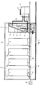
- Fig. 1 shows purely schematically an arrangement 10 for operating heat generating devices 12, 14, 16, 18, in particular IT components such as servers.
- the order comprises a space 20 in which the heat-generating devices 12, 14, 16, 18 and at least one air conditioning device 22 for cooling the heat-generating devices 12, 14, 16, 18 are arranged.
- the air conditioning device 22 comprises at least one control / regulating unit 24, a compressor 26, a fan 28 of a condenser, a fan 30 of an evaporator as well as an actuator 32 and / or at least one temperature sensor 34 or pressure sensor as electrical operating means.
- the electrical operating means 26, 28, 30 of the air conditioning device 22 are designed as DC voltage components and are connected to a DC voltage supply 36 required for the operation of the heat-generating devices 12, 14, 16, and from this directly, i.e.. H. can be supplied with DC voltage without the interposition of a converter.
- the space 20 has a floor 38 with an underlying cavity 40.
- the fan 30 is preferably arranged in the cavity 40 in the form of a housing-free radial fan 30 of the air conditioning device 20.
- This furthermore comprises a cooling device such as heat exchanger 42 with an upstream filter 44.
- the cooling arrangement is arranged in a housing 46.
- the housing 46 is set up on the base 38 and aligned with an opening in the base 38 in order to enable a connection to the fan 30.
- the cooling device such as heat exchanger 42
- a cooling unit such as a condenser 48
- the condenser 48 is connected via a line 50 to the heat exchanger 42, which is connected to the compressor 26 via a line 52.
- the compressor is connected to the condenser 48 via a line 54.
- the heat exchanger 42, the compressor 26 and the condenser 48 together with the lines 50, 52, 54 form a cooling circuit through which the cooling fluid required for cooling the air can flow.
- the DC voltage feed 36 is connected via electrical lines 56 directly to power supplies 58, 60, 62, 64 of the individual servers 12, 14, 16, 18, which are arranged in racks such as racks 66, 68, 70, 72.
- the air conditioning device 22 is connected directly to the DC voltage feed 36 via the electrical line 56.
- Fig. 2 shows purely schematically a circuit diagram for interconnecting the electrical equipment 24, 26, 28, 30 with the DC voltage feed 36.
- the current distribution 74 of the air conditioning device 22 is connected to the DC voltage feed 36 via the energy supply line 56.
- the current distribution 74 comprises a main switch 76, which is connected on the input side to the DC voltage feed 36 and on the output side to automatic circuit breakers 78, 80, 82, 84.
- the control voltage is protected by a fuse element 88.
- the evaporator fan 30, the condenser fan 28 and the compressor 26 in the form of a DC motor are each connected to DC supply voltage via one of the circuit breakers 80, 82.
- the arrangement 10 is distinguished from the prior art in that only a single DC voltage supply is required for the entire arrangement. As a result, considerable costs can be saved both for the components for the energy supply and for the installation.
Landscapes
- Engineering & Computer Science (AREA)
- General Engineering & Computer Science (AREA)
- Power Engineering (AREA)
- Chemical & Material Sciences (AREA)
- Combustion & Propulsion (AREA)
- Mechanical Engineering (AREA)
- Theoretical Computer Science (AREA)
- Physics & Mathematics (AREA)
- General Physics & Mathematics (AREA)
- Cooling Or The Like Of Electrical Apparatus (AREA)
- Air Conditioning Control Device (AREA)
Description
- Die Erfindung bezieht sich auf ein Verfahren zum Kühlen von in einem Raum angeordneten wärmeerzeugenden Geräten, insbesondere IT-Geräten, nach dem Oberbegriff des Anspruchs 1 sowie auf eine Anordnung nach dem Oberbegriff des Anspruchs 5 zur Durchführung des Verfahrens.
- Die
DE 43 43 611 C2 betrifft eine Anordnung, umfassend ein Klimagerät, bei dem die elektrischen Komponenten in Form von Aktoren, Sensoren und Steuereinheiten als Wechselstromkomponenten ausgebildet sind. Diese können zwar mit Gleichstrom betrieben werden, wobei allerdings zwischen einer Gleichstromquelle und den Wechselstromkomponenten ein Gleichspannungswandler mit Gleichspannungs-Zwischenkreis und Wechselrichter vorgesehen ist. - Gemäß einem Artikel von Rene Mosbacher: "Mit Gleichstrom im Rechenzentrum sparen" besteht der Trend, die IT-Hardware eines Rechenzentrums mit Gleichstrom statt mit dem üblichen Wechselstrom zu betreiben, um Energie und somit Kosten zu sparen. Die IT-Hardware wird normalerweise mit 230 V Wechselstrom versorgt. Weil die elektronischen Bauteile aber Gleichstrom benötigen, muss der Wechselstrom in den Netzteilen der Geräte in Niederspannung gewandelt und gleichgerichtet werden. Bei jeder Umwandlung entstehen aber Verluste in Form von Wärme. Diese Wärme muss schließlich wieder von der Kühlung des Rechenzentrums abgeführt werden, was zusätzlich Energie verbraucht.
- Die
DE 10 2011 107 688 A1 betrifft ein Rechenzentrum mit mindestens einer aus mehreren Servern bestehenden Rechenanlage, mit einer Energieversorgungsanlage zur Hauptenergieversorgung des Rechenzentrums und mit einer Kühlanlage zur Kühlung der Rechenanlage. Dabei ist vorgesehen, dass die Energieversorgungsanlage mindestens einen Gleichspannungserzeuger aufweist, und dass ein Gleichspannungsnetz die mindestens eine Rechenanlage und die Energieversorgungsanlage verbindet. Die Kühlanlage ist als Sorptionskälteanlage ausgebildet, die über ein Abwärmeleitungssystem mit Abwärme der Energieversorgungsanlage versorgt wird. - Damit offenbart die
DE 10 2011 107 688 A1 ein Verfahren zum Kühlen gemäß dem Oberbegriff von Anspruch 1 sowie eine Anordnung gemäß dem Oberbegriff von Anspruch 5. - Die
DE 10 2011 118 272 A1 bezieht sich auf eine Klimatisierungsvorrichtung zum Temperieren von elektronischen Komponenten. Die Klimatisierungsvorrichtung ist als eine Schaltschrank-Klimatisierungseinrichtung mit einem quaderförmigen Gehäuse ausgebildet, wobei das quaderförmige Gehäuse als 19"-Einschubgehäuse ausgebildet ist. - Die Klimatisierungsvorrichtung weist einen gleichstromgespeisten Kompressor auf, sodass die Klimatisierungsvorrichtung unabhängig vom Netzstrom betrieben und beispielsweise mit Batterien oder Akkumulatoren mit Strom versorgt werden kann. Die Klimatisierungsvorrichtung wird mit einer 24 V DC Versorgung oder einer 48 V DC Versorgung betrieben.
- Die
US 2007/0165377 A1 betrifft ein System zur Kühlung eines Rechenzentrums mit einer Vielzahl von Kühlracks, wobei jedes Kühlrack ein Gehäuse mit Kühlsystemkomponenten umfasst. - Die
US 2014/0103713 A1 bezieht sich auf ein Kühlsystem für Server mit AC- und DC-Spannungsquellen und ein Verfahren zum Betrieb eines solchen, wobei zusätzlich zu einer DC-Spannungsversorgung eine AC-Spannungsversorgung vorgesehen ist. - Die
EP 2 372 261 A2 bezieht sich auf ein Klimagerät unter Verwendung von Photovoltaikenergie. Das Klimagerät umfasst eine Photovoltaikzelle zur Umwandlung von Photovoltaikenergie in Gleichspannung, einen inneren Wärmetauscher und einen äußeren Wärmetauscher. Die durch Photovoltaik erzeugte Energie versorgt den inneren Wärmetauscher und wird als zumindest eine Stand-by-Power in einem Stand-by-Modus verwendet. - Die
CN 201310674418 - Ein ähnliches Photovoltaik-Gleichstrom-Mikro-Gridsystem ist in der
CN 103 618 372 A beschrieben. - Die
CN 103 208 852 A bezieht sich auf das technische Gebiet eines Rechenzentrums und beschreibt eine umweltfreundliche Energieversorgungseinrichtung für ein solches. - Das IT-Equipment ist als Gleichstrom-Equipment ausgebildet. In diesem Zusammenhang wird auch die Verwendung eines Gleichspannungsklimatisierungsgerätes beschrieben.
- Davon ausgehend liegt der vorliegenden Erfindung die Aufgabe zugrunde, ein Verfahren sowie eine Anordnung zum Kühlen von wärmeerzeugenden Geräten der eingangs genannten Art derart weiterzubilden, dass dessen Energieversorgung vereinfacht und der Energieverbrauch reduziert wird.
- Die Aufgabe wird erfindungsgemäß durch ein Verfahren mit den Merkmalen des Anspruchs 1 gelöst.
- Das erfindungsgemäße Verfahren zeichnet sich gegenüber dem Stand der Technik dadurch aus, dass als elektrische Betriebsmittel des Luftkonditionierungsgerätes Gleichspannungskomponenten verwendet werden, die unmittelbar mit derselben zum Betrieb der wärmeerzeugenden Geräte erforderlichen Versorgungsgleichspannung betrieben werden. Unmittelbar bedeutet dies, dass die elektrischen Betriebsmittel mit derselben Gleichspannungsquelle und derselben Gleichspannung betrieben werden, mit der auch die wärmeerzeugenden Geräte betrieben werden. Dadurch können Kosten für eine zusätzliche Wechselspannungsversorgung eingespart werden.
- Eine bevorzugte Verfahrensweise zeichnet sich dadurch aus, dass insbesondere sämtliche der elektrischen Betriebsmittel des Luftkonditionierungsgerätes in Form von Niederspannungskomponenten wie der zumindest eine Antrieb für den Ventilator des Verdampfers, den Ventilator des Kondensators und/oder den Kompressor unmittelbar mit der Versorgungsgleichspannung betrieben werden. Dabei ist vorgesehen, dass als Betriebsmittel solche verwendet werden, die eine Nennspannung aufweisen, die der Versorgungsgleichspannung entspricht.
- Eine weitere bevorzugte Verfahrensweise zeichnet sich dadurch aus, dass insbesondere sämtliche elektrische Betriebsmittel in Form von Kleinspannungskomponenten wie die zumindest eine Steuer-/Regeleinheit, der zumindest eine Aktor wie Stellantrieb und/oder der zumindest eine Sensor wie Temperatursensor über einen DC/DC-Wandler mit der Versorgungsgleichspannung betrieben werden. Dabei ist vorgesehen, dass eine Gleichspannungseinspeisung die Versorgungsgleichspannung von vorzugsweise UVDC = 400 VDC und der DC/DC-Wandler eine Steuergleichspannung USDC von vorzugsweise USDC = 24 VDC bereitstellt.
- Die Aufgabe wird erfindungsgemäß durch eine Anordnung mit den Merkmalen des Anspruchs 5 gelöst. Dabei ist vorgesehen, dass die elektrischen Betriebsmittel des Luftkonditionierungsgerätes als Gleichspannungskomponenten ausgebildet und unmittelbar mit der zum Betrieb der wärmeerzeugenden Geräte erforderlichen Versorgungsgleichspannung der Gleichspannungseinspeisung verbunden sind.
- Gegenüber dem Stand der Technik wird der Vorteil erreicht, dass auf zusätzliche Gleichspannungswandler, Gleichspannungs-Zwischenkreise und Umrichter verzichtet werden kann, was sowohl eine Kosten-, Energie- und Raumersparnis zur Folge hat.
- Bei einer bevorzugten Ausführungsform sind die elektrischen Betriebsmittel in Form des zumindest einen Antriebs für den Ventilator des Verdampfers, den Ventilator des Kondensators und den Kompressor als Gleichstrommotor mit einer Nennspannung ausgebildet, die vorzugsweise der Nennspannung der Gleichspannungsversorgung entspricht. Die elektrischen Gleichspannungs-Betriebsmittel sind vorzugsweise jeweils über einen Sicherungsautomaten unmittelbar mit der Gleichspannungsversorgung verbunden.
- Eine weitere bevorzugte Ausführungsform sieht vor, dass die elektrischen Betriebsmittel in Form der zumindest einen Steuer-/Regeleinheit, des zumindest einen Aktors wie Stellantriebs und/oder des zumindest einen Sensors wie Temperatursensor oder Drucksensor über einen DC/DC-Wandler mit der Gleichspannungsversorgung verbunden sind.
- Vorzugsweise liefert die Gleichspannungsversorgung eine Versorgungsgleichspannung UVDC von UVDC = 400 V DC und der DC/DC-Wandler eine Steuergleichspannung USDC von USDC = 24 V DC.
- Weitere Einzelheiten, Vorteile und Merkmale ergeben sich nicht nur aus den Ansprüchen, sondern auch aus der nachfolgenden Beschreibung eines der Zeichnung zu entnehmenden bevorzugten Ausführungsbeispiels.
- Es zeigen:
- Fig. 1
- eine schematische Seitenansicht einer Anordnung zum Betreiben von wärmeerzeugenden Geräten, umfassend die in einem Raum angeordneten wärmeerzeugenden Geräten sowie zumindest ein Luftkonditionierungsgerät, und
- Fig. 2
- einen Schaltplan zur Verschaltung elektrischer Betriebsmittel des Luftkonditionierungsgerätes mit Gleichspannung.
-
Fig. 1 zeigt rein schematisch eine Anordnung 10 zum Betrieb von wärmeerzeugenden Geräten 12, 14, 16, 18, insbesondere IT-Komponenten wie Server. Die Anordnung umfasst einen Raum 20, in dem die wärmeerzeugenden Geräte 12, 14, 16, 18 sowie zumindest ein Luftkonditionierungsgerät 22 zur Kühlung der wärmeerzeugenden Geräte 12, 14, 16, 18 angeordnet sind. Das Luftkonditionierungsgerät 22 umfasst als elektrische Betriebsmittel zumindest eine Steuer-/Regeleinheit 24, einen Kompressor 26, einen Ventilator 28 eines Kondensators, einen Ventilator 30 eines Verdampfers sowie einen Stellantrieb 32 und/oder zumindest einen Temperatursensor 34 oder Drucksensor. - Gemäß der Erfindung ist vorgesehen, dass die elektrischen Betriebsmittel 26, 28, 30 des Luftkonditionierungsgerätes 22 als Gleichspannungskomponenten ausgebildet und mit einer zum Betrieb der wärmeerzeugenden Geräte 12, 14, 16, 18 erforderlichen Gleichspannungseinspeisung 36 verbunden sind und von dieser unmittelbar, d. h. ohne Zwischenschaltung eines Wandlers mit Gleichspannung versorgt werden.
- Der Raum 20 weist einen Boden 38 mit darunterliegendem Hohlraum 40 auf. In dem Hohlraum 40 ist der Ventilator 30 vorzugsweise in Form eines gehäuselosen RadialVentilators 30 des Luftkonditionierungsgerätes 20 angeordnet. Dieses umfasst des Weiteren eine Kühleinrichtung wie Wärmetauscher 42 mit vorgeordnetem Filter 44. Die Kühlanordnung ist in einem Gehäuse 46 angeordnet. Dabei wird das Gehäuse 46 auf dem Boden 38 aufgestellt und auf eine Öffnung des Bodens 38 ausgerichtet, um eine Verbindung mit dem Ventilator 30 zu ermöglichen.
- Die Kühleinrichtung wie Wärmetauscher 42 ist mit einem außerhalb des Raums 20 angeordneten Kühlaggregat wie Kondensator 48 mit Ventilator 28 verbunden. Der Kondensator 48 ist über eine Leitung 50 mit dem Wärmetauscher 42 verbunden, der über eine Leitung 52 mit dem Verdichter 26 verbunden ist. Der Verdichter ist über eine Leitung 54 mit dem Kondensator 48 verbunden. Der Wärmetauscher 42, der Verdichter 26 und der Kondensator 48 bilden zusammen mit den Leitungen 50, 52, 54 einen Kühlkreislauf, durch den das zum Kühlen der Luft erforderliche Kühlfluid strömen kann. Insoweit wird jedoch auf hinlänglich bekannte Konstruktionen verwiesen, so dass es näherer Erläuterungen nicht bedarf.
- Bei der hier beschriebenen Anlage zum Betrieb der wärmeerzeugenden Geräte 12, 14, 16, 18 wird die Versorgungsspannung durch die zentrale Gleichspannungseinspeisung 36 als Gleichspannung UVDC in einer Höhe von z.B. UVDC = 400 V DC bereitgestellt. Die Gleichspannungseinspeisung 36 ist über elektrische Leitungen 56 direkt mit Stromversorgungen 58, 60, 62, 64 der einzelnen Server 12, 14, 16, 18 verbunden, die in Gestellen wie Racks 66, 68, 70, 72 angeordnet sind.
- Gemäß der Erfindung ist vorgesehen, dass vorzugsweise sämtliche elektrische Betriebsmittel des Luftkonditionierungsgerätes 22 mit Gleichspannung betrieben werden. Hierzu ist das Luftkonditionierungsgerät 22 über die elektrische Leitung 56 direkt mit der Gleichspannungseinspeisung 36 verbunden. Die elektrische Leitung 56 ist mit einer Stromverteilung 74 des Luftkonditionierungsgeräts 22 verbunden, von der aus die elektrischen Betriebsmittel wie Verdampfer-Ventilator 30, Kondensator-Ventilator 28, Kompressor 26 sowie Steuer-/Regeleinheit 24 mit Versorgungsgleichspannung, d.h. im vorliegenden Fall UVDC = 400 V DC versorgt werden.
-
Fig. 2 zeigt rein schematisch einen Schaltplan zur Verschaltung der elektrischen Betriebsmittel 24, 26, 28, 30 mit der Gleichspannungseinspeisung 36. Die Stromverteilung 74 des Luftkonditionierungsgerätes 22 ist über die Energieversorgungsleitung 56 mit der Gleichspannungseinspeisung 36 verbunden. Die Stromverteilung 74 umfasst einen Hauptschalter 76, der eingangsseitig mit der Gleichspannungseinspeisung 36 und ausgangsseitig mit Sicherungsautomaten 78, 80, 82, 84 verbunden ist. - An den Sicherungsautomat 78 ist ein DC/DC-Wandler 86 angeschlossen, der eine Steuerspannung USDC mit USDC = 24 V DC für die elektrischen Niederspannungs-Betriebsmittel wie die Steuer-/Regeleinheit 24, Stellantriebe 32 und Sensoren 34 bereitstellt. Die Steuerspannung ist über ein Sicherungselement 88 abgesichert.
- Der Verdampfer-Ventilator 30, der Kondensator-Ventilator 28 sowie der Kompressor 26 in Form eines Gleichspannungsmotors sind jeweils über einen der Sicherungsautomaten 80, 82 mit Versorgungsgleichspannung verbunden.
- Die Anordnung 10 zeichnet sich gegenüber dem Stand der Technik dadurch aus, dass nur eine einzige Gleichspannungsversorgung für die gesamte Anordnung erforderlich ist. Dadurch können sowohl bei den Komponenten für die Energieversorgung als auch bei der Installation erhebliche Kosten eingespart werden.
Claims (8)
- Verfahren zum Kühlen von in einem Raum (20) angeordneten und mit einer Versorgungsgleichspannung (UVDC) in Form einer Niederspannung von vorzugsweise 400 VDC versorgten wärmeerzeugenden Geräten (12, 14, 16, 18), insbesondere IT-Geräten, mittels eines Luftkonditionierungsgerätes (22), wobei das Luftkonditionierungsgerät (22) elektrische Betriebsmittel (24, 26, 28, 30), insbesondere in Form von zumindest einer Steuer-/Regeleinheit, zumindest einem Aktor wie Kompressor, Ventilator eines Kondensators, Ventilator eines Verdampfers oder Stellantrieb und/oder zumindest einem Sensor wie Temperatursensor umfasst,
dadurch gekennzeichnet
dass als elektrische Betriebsmittel (24, 26, 28, 30) des Luftkonditionierungsgerätes (22) Gleichspannungskomponenten verwendet werden, die unmittelbar mit derselben zum Betrieb der wärmeerzeugenden Geräte (14, 16, 18, 20) erforderlichen Versorgungsgleichspannung (UVDC) betrieben werden. - Verfahren nach Anspruch 1,
dadurch gekennzeichnet,
dass die elektrischen Betriebsmittel (26, 28, 30) des Luftkonditionierungsgerätes (22) in Form von Niederspannungskomponenten wie Gleichstrommotoren für den Ventilator des Verdampfers, den Ventilator des Kondensators und/oder den Kompressor unmittelbar mit der Versorgungsgleichspannung (UVDC) betrieben werden und/oder dass als Betriebsmittel solche verwendet werden, die eine Nennspannung aufweisen, die der Versorgungsgleichspannung (UVDC) entspricht. - Verfahren nach Anspruch 1 oder 2,
dadurch gekennzeichnet,
dass die elektrischen Betriebsmittel (24, 32, 34) in Form von Kleinspannungskomponenten wie die der zumindest einen Steuer-/ Regeleinheit, des zumindest einen Aktors wie Stellantrieb und/oder des zumindest einen Sensors wie Temperatursensor über einen DC/DC-Wandler (86) mit Gleichspannung betrieben werden. - Verfahren nach zumindest einem der vorhergehenden Ansprüche,
dadurch gekennzeichnet
dass eine Gleichspannungseinspeisung (36) die Versorgungsgleichspannung (UVDC) von vorzugsweise UVDC = 400 V DC und der DC/DC-Wandler (86) eine Steuergleichspannung (USDC) von vorzugsweise USDC = 24 V DC bereitstellt. - Anordnung (10), umfassend in einem Raum (20) angeordnete und mit einer Versorgungsgleichspannung (UVDC) einer Gleichspannungseinspeisung (36) verbundene wärmeerzeugende Geräte (12, 14, 16, 18), insbesondere IT-Geräte, sowie ein in dem Raum (20) angeordnetes Luftkonditionierungsgerät (22) zum Kühlen der wärmeerzeugenden Geräte (12, 14, 16, 18), wobei das Luftkonditionierungsgerät elektrische Betriebsmittel, insbesondere in Form von zumindest einer Steuer-/Regeleinheit (24), einem Aktor wie Kompressor, Ventilator eines Kondensators (28), Ventilator eines Verdampfers (30) oder Stellantrieb (32) und/oder zumindest einem Sensor (34) wie Temperatursensor des Luftkonditionierungsgerätes (22) umfasst,
dadurch gekennzeichnet,
dass die elektrischen Betriebsmittel (24, 26, 28, 30, 32, 34) des Luftkonditionierungsgerätes (22) als Gleichspannungskomponenten ausgebildet und unmittelbar mit derselben zum Betrieb der wärmeerzeugenden Geräte erforderlichen Versorgungsgleichspannung (UVDC) der Gleichspannungseinspeisung (36) verbunden sind. - Anordnung nach Anspruch 5,
dadurch gekennzeichnet,
dass die elektrischen Betriebsmittel (26, 28, 30) des Luftkonditionierungsgerätes (22) in Form von Antrieben für den zumindest einen Ventilator des Verdampfers, den Ventilator des Kondensators und/oder den Kompressor als Gleichstrommotor ausgebildet sind und/oder dass die Betriebsmittel eine Nennspannung aufweisen, die der Versorgungsgleichspannung (UVDC) entspricht. - Anordnung nach zumindest einem der vorhergehenden Ansprüche 5 und 6,
dadurch gekennzeichnet,
dass die elektrischen Betriebsmittel (24, 32, 34) in Form der zumindest einen Steuer-/ Regeleinheit, des zumindest einen Aktors wie Stellantriebs und/oder des zumindest einen Sensors wie Temperatursensors über einen DC/DC-Wandler (86) mit der Versorgungsgleichspannung (UVDC) verbunden sind. - Anordnung nach zumindest einem der vorhergehenden Ansprüche 5 bis 7,
dadurch gekennzeichnet
dass die Gleichspannungseinspeisung (36) die Versorgungsgleichspannung (UVDC) von UVDC = 400 V DC und der DC/DC-Wandler (86) eine Steuergleichspannung (USDC) von USDC = 24 V DC bereitstellt.
Applications Claiming Priority (2)
| Application Number | Priority Date | Filing Date | Title |
|---|---|---|---|
| DE102014110363.7A DE102014110363A1 (de) | 2014-07-23 | 2014-07-23 | Verfahren und Anordnung zum Betrieb eines Luftkonditionierungsgerätes zum Kühlen von wärmeerzeugenden Geräten sowie Luftkonditionierungsgerät |
| PCT/EP2015/065710 WO2016012255A1 (de) | 2014-07-23 | 2015-07-09 | Luftkonditionierungsgerät zum kühlen von wärmeerzeugenden komponenten, verfahren zum kühlen und anordnung aus luftkonditionierungsgerät und wärmeerzeugenden geräten |
Publications (2)
| Publication Number | Publication Date |
|---|---|
| EP3172494A1 EP3172494A1 (de) | 2017-05-31 |
| EP3172494B1 true EP3172494B1 (de) | 2020-02-12 |
Family
ID=53546602
Family Applications (1)
| Application Number | Title | Priority Date | Filing Date |
|---|---|---|---|
| EP15738036.1A Active EP3172494B1 (de) | 2014-07-23 | 2015-07-09 | Verfahren zum kühlen und anordnung aus luftkonditionierungsgerät und wärmeerzeugenden geräten |
Country Status (4)
| Country | Link |
|---|---|
| EP (1) | EP3172494B1 (de) |
| KR (1) | KR102556568B1 (de) |
| DE (1) | DE102014110363A1 (de) |
| WO (1) | WO2016012255A1 (de) |
Families Citing this family (1)
| Publication number | Priority date | Publication date | Assignee | Title |
|---|---|---|---|---|
| CN109668207B (zh) * | 2018-11-16 | 2021-04-02 | 天水电气传动研究所有限责任公司 | 一种钻机电控系统在低温环境中可靠运行的方法 |
Family Cites Families (9)
| Publication number | Priority date | Publication date | Assignee | Title |
|---|---|---|---|---|
| DE4343611C2 (de) | 1992-12-16 | 1998-04-09 | Hansa Ventilatoren Masch | Klimagerät |
| US7365973B2 (en) * | 2006-01-19 | 2008-04-29 | American Power Conversion Corporation | Cooling system and method |
| JP4946930B2 (ja) * | 2008-03-18 | 2012-06-06 | パナソニック株式会社 | 空気調和装置およびそれを具備する格納装置 |
| KR101176499B1 (ko) * | 2010-03-22 | 2012-08-22 | 엘지전자 주식회사 | 태양광을 이용한 공기조화기 |
| DE102011107688A1 (de) * | 2011-07-13 | 2013-01-17 | Deutsches Zentrum für Luft- und Raumfahrt e.V. | Rechenzentrum |
| DE102011118272A1 (de) * | 2011-11-11 | 2013-05-16 | Seifert Mtm Systems Malta Ltd. | Klimatisierungsvorrichtung |
| TWI510746B (zh) * | 2012-10-12 | 2015-12-01 | Delta Electronics Inc | 具有交流與直流供電之伺服器冷卻系統及其操作方法 |
| CN103208852A (zh) * | 2013-04-23 | 2013-07-17 | 汕尾芯灵电子科技有限公司 | 一种绿色能源数据中心系统 |
| CN103618372B (zh) * | 2013-12-11 | 2016-04-06 | 厦门大学 | 一种光伏直流微电网系统 |
-
2014
- 2014-07-23 DE DE102014110363.7A patent/DE102014110363A1/de not_active Withdrawn
-
2015
- 2015-07-09 EP EP15738036.1A patent/EP3172494B1/de active Active
- 2015-07-09 KR KR1020177004978A patent/KR102556568B1/ko active Active
- 2015-07-09 WO PCT/EP2015/065710 patent/WO2016012255A1/de not_active Ceased
Non-Patent Citations (1)
| Title |
|---|
| None * |
Also Published As
| Publication number | Publication date |
|---|---|
| WO2016012255A1 (de) | 2016-01-28 |
| KR20170039214A (ko) | 2017-04-10 |
| EP3172494A1 (de) | 2017-05-31 |
| KR102556568B1 (ko) | 2023-07-18 |
| DE102014110363A1 (de) | 2016-01-28 |
Similar Documents
| Publication | Publication Date | Title |
|---|---|---|
| EP3428000B1 (de) | Vorrichtung zum laden mindestens einer batterie | |
| EP2567424B1 (de) | Elektrischer energiespeicher mit kühlvorrichtung | |
| EP2058724A2 (de) | Verfahren und System zur Nutzung der Abwärme eines Computersystems | |
| DE102017119867B4 (de) | Leistungsteil | |
| AT501422B1 (de) | Wechselrichtersystem zum einspeisen in ein 3-phasennetz sowie wechselrichteranlage für ein 3-phasennetz | |
| DE102014208499A1 (de) | Kühlkreislauf mit Bypass-Fließpfad zur Kühlung eines Umrichterinnenraums | |
| DE102018109614A1 (de) | Systemintegration von elektrischen Komponenten in Elektro- oder Hybridfahrzeugen | |
| DE102018113174A1 (de) | Universelles Ladegerät für Gleich- und Wechselstromladen | |
| EP3563650B1 (de) | Kühlvorrichtung, umrichter mit einer kühlvorrichtung und verfahren zur kühlung eines umrichters | |
| DE102017116109A1 (de) | Steuerungselektronik für kältetechnische Anlagen | |
| EP2898596A1 (de) | Thermodynamische kreisprozessanlage | |
| DE202009012751U1 (de) | Stromrichteranordnung | |
| EP3785361A1 (de) | Schaltungsanordnung zur zwischenkreissymmetrierung | |
| WO2016012255A1 (de) | Luftkonditionierungsgerät zum kühlen von wärmeerzeugenden komponenten, verfahren zum kühlen und anordnung aus luftkonditionierungsgerät und wärmeerzeugenden geräten | |
| DE102021133042A1 (de) | Ladestation für ein Elektro- oder Hybridfahrzeug | |
| DE112021006997T5 (de) | Klimaanlage | |
| DE102009054374A1 (de) | Belastungswiderstandsanordnung | |
| DE102012008873A1 (de) | Vorrichtung und Verfahren zum Belüften einer in der Vorrichtung eingebauten Leistungselektronik | |
| EP1260123B1 (de) | Schaltgehäuse mit einem kühlgerät | |
| EP2257147A1 (de) | Kühlgerät | |
| DE102023122751B3 (de) | Schaltschrankanordnung mit Wärmerückgewinnung, ein entsprechendes Verfahren sowie eine Infrastruktur für die Wärmeenergieversorgung | |
| DE102014203382A1 (de) | Modular aufgebautes Wechselrichtersystem sowie Wandlermodule zum Aufbau eines entsprechenden Wechselrichtersystems | |
| EP3531157B1 (de) | Magnetresonanzeinrichtung mit gemeinsamer kühleinrichtung für mehrere elektronikkomponenten und verfahren zum herstellen einer solchen magnetresonanzeinrichtung | |
| DE102016204175A1 (de) | System, vorzugsweise für eine Temperaturregulierung eines Volumens | |
| DE202012013242U1 (de) | Batteriewechselrichter und Vorrichtung zur Versorgung eines Hauses mit elektrischer Energie |
Legal Events
| Date | Code | Title | Description |
|---|---|---|---|
| STAA | Information on the status of an ep patent application or granted ep patent |
Free format text: STATUS: THE INTERNATIONAL PUBLICATION HAS BEEN MADE |
|
| PUAI | Public reference made under article 153(3) epc to a published international application that has entered the european phase |
Free format text: ORIGINAL CODE: 0009012 |
|
| STAA | Information on the status of an ep patent application or granted ep patent |
Free format text: STATUS: REQUEST FOR EXAMINATION WAS MADE |
|
| 17P | Request for examination filed |
Effective date: 20170222 |
|
| AK | Designated contracting states |
Kind code of ref document: A1 Designated state(s): AL AT BE BG CH CY CZ DE DK EE ES FI FR GB GR HR HU IE IS IT LI LT LU LV MC MK MT NL NO PL PT RO RS SE SI SK SM TR |
|
| AX | Request for extension of the european patent |
Extension state: BA ME |
|
| DAV | Request for validation of the european patent (deleted) | ||
| DAX | Request for extension of the european patent (deleted) | ||
| REG | Reference to a national code |
Ref country code: DE Ref legal event code: R079 Ref document number: 502015011709 Country of ref document: DE Free format text: PREVIOUS MAIN CLASS: F24F0001000000 Ipc: F24F0001000300 |
|
| RIC1 | Information provided on ipc code assigned before grant |
Ipc: H05K 7/20 20060101ALI20190716BHEP Ipc: H02J 1/06 20060101ALI20190716BHEP Ipc: G06F 1/26 20060101ALI20190716BHEP Ipc: F24F 1/0003 20190101AFI20190716BHEP Ipc: F24F 1/00 20190101ALI20190716BHEP Ipc: H02J 1/00 20060101ALI20190716BHEP |
|
| GRAP | Despatch of communication of intention to grant a patent |
Free format text: ORIGINAL CODE: EPIDOSNIGR1 |
|
| STAA | Information on the status of an ep patent application or granted ep patent |
Free format text: STATUS: GRANT OF PATENT IS INTENDED |
|
| INTG | Intention to grant announced |
Effective date: 20190829 |
|
| GRAS | Grant fee paid |
Free format text: ORIGINAL CODE: EPIDOSNIGR3 |
|
| GRAA | (expected) grant |
Free format text: ORIGINAL CODE: 0009210 |
|
| STAA | Information on the status of an ep patent application or granted ep patent |
Free format text: STATUS: THE PATENT HAS BEEN GRANTED |
|
| AK | Designated contracting states |
Kind code of ref document: B1 Designated state(s): AL AT BE BG CH CY CZ DE DK EE ES FI FR GB GR HR HU IE IS IT LI LT LU LV MC MK MT NL NO PL PT RO RS SE SI SK SM TR |
|
| REG | Reference to a national code |
Ref country code: GB Ref legal event code: FG4D Free format text: NOT ENGLISH |
|
| REG | Reference to a national code |
Ref country code: CH Ref legal event code: EP |
|
| REG | Reference to a national code |
Ref country code: AT Ref legal event code: REF Ref document number: 1232621 Country of ref document: AT Kind code of ref document: T Effective date: 20200215 |
|
| REG | Reference to a national code |
Ref country code: IE Ref legal event code: FG4D Free format text: LANGUAGE OF EP DOCUMENT: GERMAN |
|
| REG | Reference to a national code |
Ref country code: DE Ref legal event code: R096 Ref document number: 502015011709 Country of ref document: DE |
|
| PG25 | Lapsed in a contracting state [announced via postgrant information from national office to epo] |
Ref country code: RS Free format text: LAPSE BECAUSE OF FAILURE TO SUBMIT A TRANSLATION OF THE DESCRIPTION OR TO PAY THE FEE WITHIN THE PRESCRIBED TIME-LIMIT Effective date: 20200212 Ref country code: NO Free format text: LAPSE BECAUSE OF FAILURE TO SUBMIT A TRANSLATION OF THE DESCRIPTION OR TO PAY THE FEE WITHIN THE PRESCRIBED TIME-LIMIT Effective date: 20200512 Ref country code: FI Free format text: LAPSE BECAUSE OF FAILURE TO SUBMIT A TRANSLATION OF THE DESCRIPTION OR TO PAY THE FEE WITHIN THE PRESCRIBED TIME-LIMIT Effective date: 20200212 |
|
| REG | Reference to a national code |
Ref country code: LT Ref legal event code: MG4D |
|
| REG | Reference to a national code |
Ref country code: NL Ref legal event code: MP Effective date: 20200212 |
|
| PG25 | Lapsed in a contracting state [announced via postgrant information from national office to epo] |
Ref country code: SE Free format text: LAPSE BECAUSE OF FAILURE TO SUBMIT A TRANSLATION OF THE DESCRIPTION OR TO PAY THE FEE WITHIN THE PRESCRIBED TIME-LIMIT Effective date: 20200212 Ref country code: LV Free format text: LAPSE BECAUSE OF FAILURE TO SUBMIT A TRANSLATION OF THE DESCRIPTION OR TO PAY THE FEE WITHIN THE PRESCRIBED TIME-LIMIT Effective date: 20200212 Ref country code: HR Free format text: LAPSE BECAUSE OF FAILURE TO SUBMIT A TRANSLATION OF THE DESCRIPTION OR TO PAY THE FEE WITHIN THE PRESCRIBED TIME-LIMIT Effective date: 20200212 Ref country code: IS Free format text: LAPSE BECAUSE OF FAILURE TO SUBMIT A TRANSLATION OF THE DESCRIPTION OR TO PAY THE FEE WITHIN THE PRESCRIBED TIME-LIMIT Effective date: 20200612 Ref country code: GR Free format text: LAPSE BECAUSE OF FAILURE TO SUBMIT A TRANSLATION OF THE DESCRIPTION OR TO PAY THE FEE WITHIN THE PRESCRIBED TIME-LIMIT Effective date: 20200513 Ref country code: BG Free format text: LAPSE BECAUSE OF FAILURE TO SUBMIT A TRANSLATION OF THE DESCRIPTION OR TO PAY THE FEE WITHIN THE PRESCRIBED TIME-LIMIT Effective date: 20200512 |
|
| PG25 | Lapsed in a contracting state [announced via postgrant information from national office to epo] |
Ref country code: NL Free format text: LAPSE BECAUSE OF FAILURE TO SUBMIT A TRANSLATION OF THE DESCRIPTION OR TO PAY THE FEE WITHIN THE PRESCRIBED TIME-LIMIT Effective date: 20200212 |
|
| PG25 | Lapsed in a contracting state [announced via postgrant information from national office to epo] |
Ref country code: RO Free format text: LAPSE BECAUSE OF FAILURE TO SUBMIT A TRANSLATION OF THE DESCRIPTION OR TO PAY THE FEE WITHIN THE PRESCRIBED TIME-LIMIT Effective date: 20200212 Ref country code: CZ Free format text: LAPSE BECAUSE OF FAILURE TO SUBMIT A TRANSLATION OF THE DESCRIPTION OR TO PAY THE FEE WITHIN THE PRESCRIBED TIME-LIMIT Effective date: 20200212 Ref country code: EE Free format text: LAPSE BECAUSE OF FAILURE TO SUBMIT A TRANSLATION OF THE DESCRIPTION OR TO PAY THE FEE WITHIN THE PRESCRIBED TIME-LIMIT Effective date: 20200212 Ref country code: SM Free format text: LAPSE BECAUSE OF FAILURE TO SUBMIT A TRANSLATION OF THE DESCRIPTION OR TO PAY THE FEE WITHIN THE PRESCRIBED TIME-LIMIT Effective date: 20200212 Ref country code: PT Free format text: LAPSE BECAUSE OF FAILURE TO SUBMIT A TRANSLATION OF THE DESCRIPTION OR TO PAY THE FEE WITHIN THE PRESCRIBED TIME-LIMIT Effective date: 20200705 Ref country code: ES Free format text: LAPSE BECAUSE OF FAILURE TO SUBMIT A TRANSLATION OF THE DESCRIPTION OR TO PAY THE FEE WITHIN THE PRESCRIBED TIME-LIMIT Effective date: 20200212 Ref country code: LT Free format text: LAPSE BECAUSE OF FAILURE TO SUBMIT A TRANSLATION OF THE DESCRIPTION OR TO PAY THE FEE WITHIN THE PRESCRIBED TIME-LIMIT Effective date: 20200212 Ref country code: DK Free format text: LAPSE BECAUSE OF FAILURE TO SUBMIT A TRANSLATION OF THE DESCRIPTION OR TO PAY THE FEE WITHIN THE PRESCRIBED TIME-LIMIT Effective date: 20200212 Ref country code: SK Free format text: LAPSE BECAUSE OF FAILURE TO SUBMIT A TRANSLATION OF THE DESCRIPTION OR TO PAY THE FEE WITHIN THE PRESCRIBED TIME-LIMIT Effective date: 20200212 |
|
| REG | Reference to a national code |
Ref country code: DE Ref legal event code: R097 Ref document number: 502015011709 Country of ref document: DE |
|
| PLBE | No opposition filed within time limit |
Free format text: ORIGINAL CODE: 0009261 |
|
| STAA | Information on the status of an ep patent application or granted ep patent |
Free format text: STATUS: NO OPPOSITION FILED WITHIN TIME LIMIT |
|
| 26N | No opposition filed |
Effective date: 20201113 |
|
| PG25 | Lapsed in a contracting state [announced via postgrant information from national office to epo] |
Ref country code: IT Free format text: LAPSE BECAUSE OF FAILURE TO SUBMIT A TRANSLATION OF THE DESCRIPTION OR TO PAY THE FEE WITHIN THE PRESCRIBED TIME-LIMIT Effective date: 20200212 |
|
| PG25 | Lapsed in a contracting state [announced via postgrant information from national office to epo] |
Ref country code: MC Free format text: LAPSE BECAUSE OF FAILURE TO SUBMIT A TRANSLATION OF THE DESCRIPTION OR TO PAY THE FEE WITHIN THE PRESCRIBED TIME-LIMIT Effective date: 20200212 Ref country code: PL Free format text: LAPSE BECAUSE OF FAILURE TO SUBMIT A TRANSLATION OF THE DESCRIPTION OR TO PAY THE FEE WITHIN THE PRESCRIBED TIME-LIMIT Effective date: 20200212 Ref country code: SI Free format text: LAPSE BECAUSE OF FAILURE TO SUBMIT A TRANSLATION OF THE DESCRIPTION OR TO PAY THE FEE WITHIN THE PRESCRIBED TIME-LIMIT Effective date: 20200212 |
|
| REG | Reference to a national code |
Ref country code: CH Ref legal event code: PL |
|
| GBPC | Gb: european patent ceased through non-payment of renewal fee |
Effective date: 20200709 |
|
| REG | Reference to a national code |
Ref country code: BE Ref legal event code: MM Effective date: 20200731 |
|
| PG25 | Lapsed in a contracting state [announced via postgrant information from national office to epo] |
Ref country code: LI Free format text: LAPSE BECAUSE OF NON-PAYMENT OF DUE FEES Effective date: 20200731 Ref country code: LU Free format text: LAPSE BECAUSE OF NON-PAYMENT OF DUE FEES Effective date: 20200709 Ref country code: FR Free format text: LAPSE BECAUSE OF NON-PAYMENT OF DUE FEES Effective date: 20200731 Ref country code: CH Free format text: LAPSE BECAUSE OF NON-PAYMENT OF DUE FEES Effective date: 20200731 Ref country code: GB Free format text: LAPSE BECAUSE OF NON-PAYMENT OF DUE FEES Effective date: 20200709 |
|
| PG25 | Lapsed in a contracting state [announced via postgrant information from national office to epo] |
Ref country code: BE Free format text: LAPSE BECAUSE OF NON-PAYMENT OF DUE FEES Effective date: 20200731 |
|
| PG25 | Lapsed in a contracting state [announced via postgrant information from national office to epo] |
Ref country code: IE Free format text: LAPSE BECAUSE OF NON-PAYMENT OF DUE FEES Effective date: 20200709 |
|
| REG | Reference to a national code |
Ref country code: AT Ref legal event code: MM01 Ref document number: 1232621 Country of ref document: AT Kind code of ref document: T Effective date: 20200709 |
|
| PG25 | Lapsed in a contracting state [announced via postgrant information from national office to epo] |
Ref country code: AT Free format text: LAPSE BECAUSE OF NON-PAYMENT OF DUE FEES Effective date: 20200709 |
|
| PG25 | Lapsed in a contracting state [announced via postgrant information from national office to epo] |
Ref country code: TR Free format text: LAPSE BECAUSE OF FAILURE TO SUBMIT A TRANSLATION OF THE DESCRIPTION OR TO PAY THE FEE WITHIN THE PRESCRIBED TIME-LIMIT Effective date: 20200212 Ref country code: MT Free format text: LAPSE BECAUSE OF FAILURE TO SUBMIT A TRANSLATION OF THE DESCRIPTION OR TO PAY THE FEE WITHIN THE PRESCRIBED TIME-LIMIT Effective date: 20200212 Ref country code: CY Free format text: LAPSE BECAUSE OF FAILURE TO SUBMIT A TRANSLATION OF THE DESCRIPTION OR TO PAY THE FEE WITHIN THE PRESCRIBED TIME-LIMIT Effective date: 20200212 |
|
| PG25 | Lapsed in a contracting state [announced via postgrant information from national office to epo] |
Ref country code: MK Free format text: LAPSE BECAUSE OF FAILURE TO SUBMIT A TRANSLATION OF THE DESCRIPTION OR TO PAY THE FEE WITHIN THE PRESCRIBED TIME-LIMIT Effective date: 20200212 Ref country code: AL Free format text: LAPSE BECAUSE OF FAILURE TO SUBMIT A TRANSLATION OF THE DESCRIPTION OR TO PAY THE FEE WITHIN THE PRESCRIBED TIME-LIMIT Effective date: 20200212 |
|
| P01 | Opt-out of the competence of the unified patent court (upc) registered |
Effective date: 20230525 |
|
| PGFP | Annual fee paid to national office [announced via postgrant information from national office to epo] |
Ref country code: DE Payment date: 20250728 Year of fee payment: 11 |