EP3173109A1 - Procédé de contrôle de la position de l'impulseur de pompe centrifuge d'assistance cardiaque - Google Patents
Procédé de contrôle de la position de l'impulseur de pompe centrifuge d'assistance cardiaque Download PDFInfo
- Publication number
- EP3173109A1 EP3173109A1 EP15197077.9A EP15197077A EP3173109A1 EP 3173109 A1 EP3173109 A1 EP 3173109A1 EP 15197077 A EP15197077 A EP 15197077A EP 3173109 A1 EP3173109 A1 EP 3173109A1
- Authority
- EP
- European Patent Office
- Prior art keywords
- impeller
- pump
- motors
- axis
- pump housing
- Prior art date
- Legal status (The legal status is an assumption and is not a legal conclusion. Google has not performed a legal analysis and makes no representation as to the accuracy of the status listed.)
- Withdrawn
Links
- 238000000034 method Methods 0.000 title claims abstract description 14
- 230000002861 ventricular Effects 0.000 claims abstract description 11
- 230000010363 phase shift Effects 0.000 claims description 3
- 239000008280 blood Substances 0.000 description 7
- 210000004369 blood Anatomy 0.000 description 7
- 208000007536 Thrombosis Diseases 0.000 description 2
- 230000015572 biosynthetic process Effects 0.000 description 2
- 238000012544 monitoring process Methods 0.000 description 2
- 229910052779 Neodymium Inorganic materials 0.000 description 1
- 238000010276 construction Methods 0.000 description 1
- 230000003247 decreasing effect Effects 0.000 description 1
- 238000010586 diagram Methods 0.000 description 1
- 238000005259 measurement Methods 0.000 description 1
- QEFYFXOXNSNQGX-UHFFFAOYSA-N neodymium atom Chemical compound [Nd] QEFYFXOXNSNQGX-UHFFFAOYSA-N 0.000 description 1
- 238000009987 spinning Methods 0.000 description 1
- 239000000725 suspension Substances 0.000 description 1
Images


Classifications
-
- A—HUMAN NECESSITIES
- A61—MEDICAL OR VETERINARY SCIENCE; HYGIENE
- A61M—DEVICES FOR INTRODUCING MEDIA INTO, OR ONTO, THE BODY; DEVICES FOR TRANSDUCING BODY MEDIA OR FOR TAKING MEDIA FROM THE BODY; DEVICES FOR PRODUCING OR ENDING SLEEP OR STUPOR
- A61M60/00—Blood pumps; Devices for mechanical circulatory actuation; Balloon pumps for circulatory assistance
- A61M60/20—Type thereof
- A61M60/205—Non-positive displacement blood pumps
- A61M60/216—Non-positive displacement blood pumps including a rotating member acting on the blood, e.g. impeller
- A61M60/226—Non-positive displacement blood pumps including a rotating member acting on the blood, e.g. impeller the blood flow through the rotating member having mainly radial components
- A61M60/232—Centrifugal pumps
-
- A—HUMAN NECESSITIES
- A61—MEDICAL OR VETERINARY SCIENCE; HYGIENE
- A61M—DEVICES FOR INTRODUCING MEDIA INTO, OR ONTO, THE BODY; DEVICES FOR TRANSDUCING BODY MEDIA OR FOR TAKING MEDIA FROM THE BODY; DEVICES FOR PRODUCING OR ENDING SLEEP OR STUPOR
- A61M60/00—Blood pumps; Devices for mechanical circulatory actuation; Balloon pumps for circulatory assistance
- A61M60/10—Location thereof with respect to the patient's body
- A61M60/122—Implantable pumps or pumping devices, i.e. the blood being pumped inside the patient's body
- A61M60/165—Implantable pumps or pumping devices, i.e. the blood being pumped inside the patient's body implantable in, on, or around the heart
- A61M60/178—Implantable pumps or pumping devices, i.e. the blood being pumped inside the patient's body implantable in, on, or around the heart drawing blood from a ventricle and returning the blood to the arterial system via a cannula external to the ventricle, e.g. left or right ventricular assist devices
-
- A—HUMAN NECESSITIES
- A61—MEDICAL OR VETERINARY SCIENCE; HYGIENE
- A61M—DEVICES FOR INTRODUCING MEDIA INTO, OR ONTO, THE BODY; DEVICES FOR TRANSDUCING BODY MEDIA OR FOR TAKING MEDIA FROM THE BODY; DEVICES FOR PRODUCING OR ENDING SLEEP OR STUPOR
- A61M60/00—Blood pumps; Devices for mechanical circulatory actuation; Balloon pumps for circulatory assistance
- A61M60/40—Details relating to driving
- A61M60/403—Details relating to driving for non-positive displacement blood pumps
- A61M60/422—Details relating to driving for non-positive displacement blood pumps the force acting on the blood contacting member being electromagnetic, e.g. using canned motor pumps
-
- A—HUMAN NECESSITIES
- A61—MEDICAL OR VETERINARY SCIENCE; HYGIENE
- A61M—DEVICES FOR INTRODUCING MEDIA INTO, OR ONTO, THE BODY; DEVICES FOR TRANSDUCING BODY MEDIA OR FOR TAKING MEDIA FROM THE BODY; DEVICES FOR PRODUCING OR ENDING SLEEP OR STUPOR
- A61M60/00—Blood pumps; Devices for mechanical circulatory actuation; Balloon pumps for circulatory assistance
- A61M60/50—Details relating to control
- A61M60/508—Electronic control means, e.g. for feedback regulation
- A61M60/538—Regulation using real-time blood pump operational parameter data, e.g. motor current
-
- A—HUMAN NECESSITIES
- A61—MEDICAL OR VETERINARY SCIENCE; HYGIENE
- A61M—DEVICES FOR INTRODUCING MEDIA INTO, OR ONTO, THE BODY; DEVICES FOR TRANSDUCING BODY MEDIA OR FOR TAKING MEDIA FROM THE BODY; DEVICES FOR PRODUCING OR ENDING SLEEP OR STUPOR
- A61M60/00—Blood pumps; Devices for mechanical circulatory actuation; Balloon pumps for circulatory assistance
- A61M60/80—Constructional details other than related to driving
- A61M60/802—Constructional details other than related to driving of non-positive displacement blood pumps
- A61M60/818—Bearings
- A61M60/82—Magnetic bearings
- A61M60/822—Magnetic bearings specially adapted for being actively controlled
Definitions
- the invention relates to a method of controlling the position of an impeller of a centrifugal ventricular assist pump, said method provided for controlling the position of the impeller in ventricular assist pumps with the impeller suspended within the blood pump chamber by means of magnetic and hydrodynamic bearings, without mechanical contact with the pump housing.
- impellers of ventricular assist pumps suspended within the pump housing with the use of a hybrid bearing comprising a hydrodynamic and a magnetic bearing.
- the pump impeller is driven by symmetrical, three-phase, brushless and sensorless motors mounted in the upper and lower part of the pump housing, said motors cooperating with the impeller mounted therebetween.
- Said impeller is equipped with permanent magnets arranged in a ring shape in the upper and lower impeller shrouds.
- Each of said motors comprises a magnetic core physically and magnetically connecting a set of nine coils electrically connected into three electrical phases.
- Each electrical limb comprises three coils geometrically shifted by 120 degrees.
- the invention relates to a method of controlling the position of an impeller of a centrifugal ventricular assist pump, wherein said impeller rotates around an axis within the pump without mechanical contact with the pump housing.
- the essence of the invention consists in that the axial position of the impeller is monitored through the analysis of amplitudes of signals of the reverse electromotive force, said signals being induced in non-powered phases of two three-phase motors of the pump, said motors being arranged opposite each other on the axis of rotation of the impeller on either side thereof in the upper and lower part of the pump housing, and the position of the impeller along its axis of rotation is adjusted by changing the control parameters of one motor with respect to the other. This results in producing a difference in electromagnetic forces generated by a system of the two aforementioned motors, and thereby a change in the axial position of the impeller is achieved.
- the position of the impeller is adjusted by changing the phase shift between the synchronically generated impulses of a cyclical current wave supplied on the coils of the motors.
- the method of controlling the position of an impeller of a ventricular assist pump according to the invention enables to move the impeller in the pump along the axis of rotation without the use of additional construction elements of the pump such as coils, magnets or cables. It is particularly advantageous that the impeller can be moved without changing the rotational speed thereof, which results in maintaining constant pump efficiency.
- the application of the method according to the invention for monitoring the axial position of the impeller eliminates the need to use additional measurement systems for monitoring the position of the impeller, which results in decreasing the overall weight of the pump.
- the method of controlling the position of an impeller was presented in an embodiment, in which said method was applied in a centrifugal ventricular assist pump.
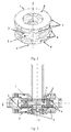
- the ventricular assist pump comprises a housing inside which there is an impeller comprising two shrouds between which there are flow channels for blood.
- the pump housing is built of two parts constituting an upper and a lower pump housing.
- both said housing parts there are identical three-phase, brushless motors.
- both said housing parts it is also possible to use identical three-phase, brushless, sensorless motors.
- both the upper shroud and the lower shroud of the impeller there are twelve permanent magnets arranged in a ring shape forming six pairs of magnetic fields shifted in the phase by 30 degrees.
- the magnets on the impeller shrouds are mutually adjacent, and at the same time they lie in the planes perpendicular to the axis of rotation of the impeller and are arranged at the same distance from the geometric centre of the impeller.
- the so constructed impeller is a common rotor for the motors located in the upper and lower pump housing.
- the magnets of the first shroud of the impeller are the rotor of the motor located in the upper pump housing
- the magnets of the second shroud of the impeller are the rotor of the motor located in the lower pump housing.
- the stator of each of the motors mounted in the pump housing comprises a magnetic core physically and magnetically connecting a set of nine coils electrically connected into three electrical phases (I, II, III).
- the distance between the magnetic core and the coils of the stator and magnets mounted on the shroud of the impeller constituting a rotor should be the same. Most preferably the distance should be 0.85 mm.
- Each limb of the circuit comprising three coils producing appropriate phases (I, II, III) is geometrically shifted by an angle of 120 degrees.
- the phases of the motor are mutually shifted by 40 degrees, thus electrically forming a star system.
- the phases are supplied in pairs (I-II, II-III, III-I) producing a magnetic field phase shifted by 40 degrees between the adjacent coils. While the pump is at work the spinning magnetic field induced in the coils is linked to the magnetic field produced by the twelve permanent magnets ring arranged in the shrouds of the impeller.
- the suspension of the impeller was constructed with the functional form of two contactless bearings: a magnetic bearing and a hydrodynamic bearing forming a hybrid bearing.
- the magnetic bearing is built of ring-shaped neodymium permanent magnets mounted in the impeller and in the pump housing.
- the aim of said bearing is to stabilize the impeller in the radial direction.
- the elements of the hydrodynamic bearing are located in the upper and in the lower shroud of the impeller.
- the aim of the hydrodynamic bearing is to prevent contact of the impeller with the pump housing in the axial direction as well as to maintain a safe gap between the impeller and the pump housing.
- the width of the gap between the impeller and the pump housing should not be smaller than 50 ⁇ m, which is several times larger than even the largest morphotic elements of blood.
- the size of said gap changes depending on the position of the impeller of the centrifugal ventricular assist pump.
- the axial position of the impeller is monitored through the analysis of amplitudes of signals of the reverse electromotive force, said signals being induced in non-powered phases of two three-phase motors of the pump.
- the position of the impeller along its axis of rotation is adjusted by changing the control parameters of one motor with respect to the other, which results in producing a difference in electromagnetic forces generated by a system of the two aforesaid motors.
- Controlling the position of the impeller inside the pump does not affect the rotational speed of the impeller or the pump efficiency.
Landscapes
- Health & Medical Sciences (AREA)
- Heart & Thoracic Surgery (AREA)
- Engineering & Computer Science (AREA)
- Cardiology (AREA)
- Biomedical Technology (AREA)
- Anesthesiology (AREA)
- Mechanical Engineering (AREA)
- Hematology (AREA)
- Life Sciences & Earth Sciences (AREA)
- Animal Behavior & Ethology (AREA)
- General Health & Medical Sciences (AREA)
- Public Health (AREA)
- Veterinary Medicine (AREA)
- External Artificial Organs (AREA)
Priority Applications (1)
| Application Number | Priority Date | Filing Date | Title |
|---|---|---|---|
| EP15197077.9A EP3173109A1 (fr) | 2015-11-30 | 2015-11-30 | Procédé de contrôle de la position de l'impulseur de pompe centrifuge d'assistance cardiaque |
Applications Claiming Priority (1)
| Application Number | Priority Date | Filing Date | Title |
|---|---|---|---|
| EP15197077.9A EP3173109A1 (fr) | 2015-11-30 | 2015-11-30 | Procédé de contrôle de la position de l'impulseur de pompe centrifuge d'assistance cardiaque |
Publications (1)
| Publication Number | Publication Date |
|---|---|
| EP3173109A1 true EP3173109A1 (fr) | 2017-05-31 |
Family
ID=55963111
Family Applications (1)
| Application Number | Title | Priority Date | Filing Date |
|---|---|---|---|
| EP15197077.9A Withdrawn EP3173109A1 (fr) | 2015-11-30 | 2015-11-30 | Procédé de contrôle de la position de l'impulseur de pompe centrifuge d'assistance cardiaque |
Country Status (1)
| Country | Link |
|---|---|
| EP (1) | EP3173109A1 (fr) |
Cited By (3)
| Publication number | Priority date | Publication date | Assignee | Title |
|---|---|---|---|---|
| CN111491677A (zh) * | 2017-12-05 | 2020-08-04 | 心脏器械股份有限公司 | 具有叶轮洗涤操作的血泵 |
| US11596783B2 (en) | 2018-03-06 | 2023-03-07 | Indiana University Research & Technology Corporation | Blood pressure powered auxiliary pump |
| EP4512460A4 (fr) * | 2022-05-23 | 2025-04-16 | RocketHeart Technology Co. Ltd | Pompe centrifuge de type à suspension magnétique |
Citations (3)
| Publication number | Priority date | Publication date | Assignee | Title |
|---|---|---|---|---|
| WO2000032257A1 (fr) * | 1998-12-03 | 2000-06-08 | Kriton Medical, Inc. | Systeme de palier magnetique actif pour pompes a sang |
| EP2405141A1 (fr) | 2009-03-05 | 2012-01-11 | NTN Corporation | Dispositif à pompe centrifuge |
| WO2013082621A1 (fr) * | 2011-12-03 | 2013-06-06 | Indiana University Research And Technology Corporation | Dispositif et procédé d'assistance de propulseur de liquide visqueux cavopulmonaire |
-
2015
- 2015-11-30 EP EP15197077.9A patent/EP3173109A1/fr not_active Withdrawn
Patent Citations (3)
| Publication number | Priority date | Publication date | Assignee | Title |
|---|---|---|---|---|
| WO2000032257A1 (fr) * | 1998-12-03 | 2000-06-08 | Kriton Medical, Inc. | Systeme de palier magnetique actif pour pompes a sang |
| EP2405141A1 (fr) | 2009-03-05 | 2012-01-11 | NTN Corporation | Dispositif à pompe centrifuge |
| WO2013082621A1 (fr) * | 2011-12-03 | 2013-06-06 | Indiana University Research And Technology Corporation | Dispositif et procédé d'assistance de propulseur de liquide visqueux cavopulmonaire |
Cited By (5)
| Publication number | Priority date | Publication date | Assignee | Title |
|---|---|---|---|---|
| CN111491677A (zh) * | 2017-12-05 | 2020-08-04 | 心脏器械股份有限公司 | 具有叶轮洗涤操作的血泵 |
| CN111491677B (zh) * | 2017-12-05 | 2023-12-01 | 心脏器械股份有限公司 | 具有叶轮洗涤操作的血泵 |
| US11596783B2 (en) | 2018-03-06 | 2023-03-07 | Indiana University Research & Technology Corporation | Blood pressure powered auxiliary pump |
| EP4512460A4 (fr) * | 2022-05-23 | 2025-04-16 | RocketHeart Technology Co. Ltd | Pompe centrifuge de type à suspension magnétique |
| JP2025518936A (ja) * | 2022-05-23 | 2025-06-19 | 航天泰心科技有限公司 | 磁気浮上型遠心ポンプ |
Similar Documents
| Publication | Publication Date | Title |
|---|---|---|
| US12285598B2 (en) | System and method for controlling the position of a levitated rotor | |
| JP7332651B2 (ja) | 血液ポンプ及び血液ポンプを動作させる方法 | |
| EP2693609B1 (fr) | Dispositif de rotation et d'entraînement, et dispositif de pompe centrifuge utilisant ce dispositif | |
| US8821365B2 (en) | Rotation drive device and centrifugal pump apparatus using the same | |
| EP3256184B1 (fr) | Mécanisme de suspension de rotor pour pompe cardiaque | |
| EP2594799B1 (fr) | Dispositif de pompe centrifuge | |
| JP6083929B2 (ja) | 遠心式ポンプ装置 | |
| JP4472610B2 (ja) | 遠心式血液ポンプ装置 | |
| US20130170970A1 (en) | Centrifugal pump apparatus | |
| WO2006053384A1 (fr) | Pompe à fluide | |
| WO2010101082A1 (fr) | Dispositif à pompe centrifuge | |
| CN102341600A (zh) | 离心式泵装置 | |
| JP5590520B2 (ja) | アキシャル型磁気浮上モータおよびアキシャル型磁気浮上モータを備えたアキシャル型磁気浮上遠心ポンプ | |
| EP3173109A1 (fr) | Procédé de contrôle de la position de l'impulseur de pompe centrifuge d'assistance cardiaque | |
| JP2010279230A5 (fr) | ||
| EP4512460A1 (fr) | Pompe centrifuge de type à suspension magnétique | |
| CN113544386B (zh) | 真空泵 | |
| CN116260303A (zh) | 一种磁悬浮高速轴流风机装置 | |
| IL288304B2 (en) | Disc pump | |
| US20240157118A1 (en) | Blood pump with three dimensional active electromagnetic suspension | |
| Miyamoto et al. | Verification of a novel 5-axis active control type bearingless canned motor pump utilizing passive magnetic bearing function for high power | |
| Kurita et al. | A double sided stator type axial self-bearing motor development for left ventricular assist devices | |
| WO2016158185A1 (fr) | Dispositif de pompe centrifuge | |
| JP5015985B2 (ja) | 遠心式血液ポンプ装置 | |
| CN121371465A (zh) | 心室辅助装置及其控制单元 |
Legal Events
| Date | Code | Title | Description |
|---|---|---|---|
| PUAI | Public reference made under article 153(3) epc to a published international application that has entered the european phase |
Free format text: ORIGINAL CODE: 0009012 |
|
| AK | Designated contracting states |
Kind code of ref document: A1 Designated state(s): AL AT BE BG CH CY CZ DE DK EE ES FI FR GB GR HR HU IE IS IT LI LT LU LV MC MK MT NL NO PL PT RO RS SE SI SK SM TR |
|
| AX | Request for extension of the european patent |
Extension state: BA ME |
|
| STAA | Information on the status of an ep patent application or granted ep patent |
Free format text: STATUS: THE APPLICATION IS DEEMED TO BE WITHDRAWN |
|
| 18D | Application deemed to be withdrawn |
Effective date: 20171201 |