EP3173776B1 - Vorrichtung und verfahren zur mischung und zum testen einer flüssigkeit - Google Patents
Vorrichtung und verfahren zur mischung und zum testen einer flüssigkeit Download PDFInfo
- Publication number
- EP3173776B1 EP3173776B1 EP15196214.9A EP15196214A EP3173776B1 EP 3173776 B1 EP3173776 B1 EP 3173776B1 EP 15196214 A EP15196214 A EP 15196214A EP 3173776 B1 EP3173776 B1 EP 3173776B1
- Authority
- EP
- European Patent Office
- Prior art keywords
- receiving portion
- liquid
- electrode
- cartridge
- testing apparatus
- Prior art date
- Legal status (The legal status is an assumption and is not a legal conclusion. Google has not performed a legal analysis and makes no representation as to the accuracy of the status listed.)
- Active
Links
Images


Classifications
-
- G—PHYSICS
- G01—MEASURING; TESTING
- G01N—INVESTIGATING OR ANALYSING MATERIALS BY DETERMINING THEIR CHEMICAL OR PHYSICAL PROPERTIES
- G01N33/00—Investigating or analysing materials by specific methods not covered by groups G01N1/00 - G01N31/00
- G01N33/48—Biological material, e.g. blood, urine; Haemocytometers
- G01N33/483—Physical analysis of biological material
- G01N33/487—Physical analysis of biological material of liquid biological material
- G01N33/49—Blood
- G01N33/4905—Determining clotting time of blood
-
- B—PERFORMING OPERATIONS; TRANSPORTING
- B01—PHYSICAL OR CHEMICAL PROCESSES OR APPARATUS IN GENERAL
- B01F—MIXING, e.g. DISSOLVING, EMULSIFYING OR DISPERSING
- B01F31/00—Mixers with shaking, oscillating, or vibrating mechanisms
- B01F31/80—Mixing by means of high-frequency vibrations above one kHz, e.g. ultrasonic vibrations
- B01F31/86—Mixing by means of high-frequency vibrations above one kHz, e.g. ultrasonic vibrations with vibration of the receptacle or part of it
-
- G—PHYSICS
- G01—MEASURING; TESTING
- G01N—INVESTIGATING OR ANALYSING MATERIALS BY DETERMINING THEIR CHEMICAL OR PHYSICAL PROPERTIES
- G01N1/00—Sampling; Preparing specimens for investigation
- G01N1/28—Preparing specimens for investigation including physical details of (bio-)chemical methods covered elsewhere, e.g. G01N33/50, C12Q
- G01N1/38—Diluting, dispersing or mixing samples
-
- G—PHYSICS
- G01—MEASURING; TESTING
- G01N—INVESTIGATING OR ANALYSING MATERIALS BY DETERMINING THEIR CHEMICAL OR PHYSICAL PROPERTIES
- G01N27/00—Investigating or analysing materials by the use of electric, electrochemical, or magnetic means
- G01N27/02—Investigating or analysing materials by the use of electric, electrochemical, or magnetic means by investigating impedance
- G01N27/04—Investigating or analysing materials by the use of electric, electrochemical, or magnetic means by investigating impedance by investigating resistance
- G01N27/06—Investigating or analysing materials by the use of electric, electrochemical, or magnetic means by investigating impedance by investigating resistance of a liquid
- G01N27/07—Construction of measuring vessels; Electrodes therefor
-
- G—PHYSICS
- G01—MEASURING; TESTING
- G01N—INVESTIGATING OR ANALYSING MATERIALS BY DETERMINING THEIR CHEMICAL OR PHYSICAL PROPERTIES
- G01N27/00—Investigating or analysing materials by the use of electric, electrochemical, or magnetic means
- G01N27/02—Investigating or analysing materials by the use of electric, electrochemical, or magnetic means by investigating impedance
- G01N27/021—Investigating or analysing materials by the use of electric, electrochemical, or magnetic means by investigating impedance before and after chemical transformation of the material
Definitions
- the present invention relates to a system and a method for mixing and testing a liquid, in particular for mixing a liquid containing blood platelets in order to perform platelet impedance aggregometry (PIA).
- PPA platelet impedance aggregometry
- Platelet impedance aggregometry systems and methods are used for the measurement of a thrombocyte function and drug-related impact on full blood coagulation.
- a mixer device is used for each measurement cell in order to mix reagents with the blood and to induce mechanical stress in the blood cells by the resulting shear forces in the moving liquid.
- US 8 877 510 B2 describes a method for conducting platelet aggregation analysis using a cartridge device having a receiving portion for receiving a blood sample and a jack portion for receiving a plug.
- a magnetic stir bar Prior to and during measurement, a magnetic stir bar is activated by an electromagnet placed under the receiving portion.
- Conventional magnetic stir bar systems always have to be formed with certain minimal dimensions in order for the stir bar mechanism to work because the stir bar needs a minimum mass and cross section for robust contactless magnetic actuation and effective liquid displacement.
- WO 2005/059532 A1 describes a cartridge device having a receiving portion for receiving a blood sample and a jack portion for receiving a plug as well as a stirring device within said receiving portion.
- US 5 674 742 A describes an integrated microfabricated instrument for manipulation, reaction and detection of microliter to picoliter samples suited for biochemical reactions such as DNA-based reactions.
- the invention provides, according to a first aspect, a system for mixing and testing a liquid, comprising: a receiving portion for receiving a liquid to be tested; a mixing unit adapted to emit ultrasound waves directed towards the receiving portion to excite Lamb waves in at least a section of the receiving portion; at least a first electrode reaching into the receiving portion and a second electrode reaching into the receiving portion; a voltage application unit adapted to apply an electrical voltage between the first electrode and the second electrode; and a measuring unit adapted to determine an electrical property of the fluid in response to the applied electrical voltage.
- the system comprises a cartridge and a testing apparatus.
- the receiving portion and the first and the second electrodes are integrated into the cartridge.
- the mixing unit is integrated into the testing apparatus.
- the cartridge is adapted to be brought into engagement with the testing apparatus such that the mixing unit is positioned to emit the ultrasound waves directed towards the receiving portion when the cartridge is brought into engagement with the testing apparatus.
- the cartridge may be brought into engagement with the testing apparatus e.g. by inserting the cartridge into the testing apparatus, by plugging the cartridge into the testing apparatus and so on.
- This allows for a creation of a relatively simple disposable cartridge with one or more measurement cells, whereas more intricate and/or more expensive elements of the system are comprised in the re-usable testing apparatus.
- system reliability may be further increased at decreasing costs.
- the liquid may in particular be a liquid containing blood platelets.
- the liquid may comprise full blood, reagents and/or saline solution.
- the reagents may in particular comprise, or consist of, reagents affecting blood coagulation.
- the ultrasound waves may in particular be so-called surface acoustic waves (SAW).
- SAW surface acoustic waves
- Lamb waves propagate in solid plates or plane sections of solids; they were first introduced in the scientific publication " On Waves in an Elastic Plate", Lamb, H., Proceedings of the Royal Society of London, Series A, Containing Papers of a Mathematical and Physical Character (1905-1934), 1917-03-01. 93 (648):114-128 .
- Lamb waves are elastic waves where the particle motion lies in a plane that contains the direction of wave propagation and the plate normal, i.e. the direction perpendicular to the plate.
- Lamb waves may have symmetric modes, for example extensional modes and/or asymmetric modes, for example flexural modes.
- the electrical property of the fluid to be determined may in particular be an electrical impedance, i.e. a measure of the opposition that the fluid presents to an alternating current when the electrical voltage is applied between the first electrode and the second electrode.
- the electrical property to be determined may be an electrical resistance.
- the first and a second electrode are configured so as not to touch each other inside the receiving portion, accordingly.
- the invention provides, according to a second aspect of the invention, a method for mixing and testing a liquid, comprising the steps of: providing the liquid to be tested in a receiving portion; emitting ultrasound waves towards the receiving portion to excite Lamb waves in at least a section of the receiving portion after the liquid is provided in the receiving portion; providing a first electrode and a second electrode in contact with the liquid in the receiving portion; applying an electrical voltage between the first electrode and the second electrode in contact with the liquid; and measuring an electrical property of the fluid in the receiving portion.
- Lamb waves can be created in at least a section of the receiving portion using ultrasound transducers.
- the Lamb waves in the receiving portion translate, via a mode conversion effect, into a motion of the liquid inside the receiving portion and thus lead to a mixing of the fluid within the receiving portion.
- the liquid in the receiving portion which forms a measurement cell, can be moved in a controlled and continuous manner without the need of a mechanical stir bar.
- Lamb waves are well suited for mixing a liquid containing blood platelets for subsequent analysis.
- Lamb waves provide an advantageously homogeneous coupling of kinetic energy into the liquid, avoiding large energy density or momentum spikes that could potentially damage the blood platelets.
- the receiving portion may be of any shape that allows for the receiving of a liquid, for example, a well-shaped structure with walls and a bottom, a cube shape, a bowl shape, a cylindrical shape, a truncated cone shape and so on.
- the receiving portion and the mixing unit which conventionally must have a certain minimum size, are, according to the present invention, well suited for a miniaturization and automation and systems with cheap consumables and low sample volume consumption.
- stir bars Conventionally, either stir bars had to be added to a disposable cell or had to be part of the disposable cell, increasing the required effort and cost in both cases.
- no part of the mixing unit has to be in direct contact with the liquid, and, in particular, no such part has to be extracted again from the mixing unit.
- the liquid comprises full blood or blood platelets
- hygiene and/or medical safety criteria may be more easily met by the system and method of the present invention.
- reagents may be pre-positioned inside the receiving portion, e.g. inside a cartridge.
- the non-homogenous mechanical force field desired for platelet impedance aggregometry can be tailored towards sample volume and measurement cell dimensions.
- the present invention is thus usable in a large variety of cases.
- the cartridge comprises a first electrical interface and the testing apparatus comprises a second electrical interface.
- the voltage application unit is integrated into the testing apparatus and is adapted to apply the electrical voltage to the first and the second electrodes over the first and the second electrical interfaces when the cartridge is brought into engagement with the testing apparatus, in which state the first and the second electrical interfaces are electrically coupled, i.e. connected.
- Electrical power may be provided to the voltage application unit by a power source of the testing apparatus, for example a connection to the general power grid or a rechargeable or non-rechargeable battery of the testing apparatus. In this way, system reliability may be further increased at decreasing costs.
- the cartridge comprises a first electrical interface and the testing apparatus comprises a second electrical interface and the measuring unit is integrated into the testing apparatus.
- the measuring unit is electrically coupled to the first and the second electrodes over the first and the second electrical interface when the cartridge is brought into engagement with the testing apparatus.
- the electrical interfaces used for coupling the measuring unit to the first and second electrode may also be used for applying the electrical voltage of the voltage application unit to the first and second electrical interface as described above.
- a technically demanding measuring unit can be provided once in a testing apparatus and can be used for a plurality of cartridges, increasing system reliability at decreasing costs.
- the mixing unit comprises at least one piezo-electric element and a frequency generator adapted to generate a periodic electrical signal to be applied to the at least one piezo-electric element so that the at least one piezo-electric element emits the ultrasound waves towards the receiving portion.
- the frequency of the periodic electrical signal may be identical to a resonance frequency of the piezo-electric element.
- any other ultrasound transducer may be provided instead of the piezo-electric element.
- the ultrasound waves may be emitted with a frequency of 10 MHz or less, preferably 2 MHz or less, in particular 1 MHz or less, especially 0.5 MHz or less.
- One or more piezo-electric elements and/or ultrasound transducers may be provided for each receiving portion comprised in the system.
- the piezo-electric elements may be provided with a dimension, or dimensions, similar to or larger than a dimension, or dimensions, of the receiving portion.
- a cross section of the piezo-electric element in a virtual plane may be equal to, or larger than, a cross-section of the receiving portion in the same virtual plane, in particular a virtual plane perpendicular to a longitudinal axis of the piezo-electric element.
- a diameter of the receiving portion contained in a virtual plane may be equal to, or smaller than, a width of the piezo-electric element within the same virtual plane.
- the frequency generator is adapted to generate the periodic electrical signal, and apply the periodic electrical signal to the at least one piezo-electric element, with a frequency of 10 MHz or less, preferably 2 MHz or less, in particular 1 MHz or less, especially between 0.5 MHz and 1 MHz.
- These frequencies may allow the use of technically less demanding configurations of the frequency generator.
- these frequency ranges are especially well suited for inducing Lamb waves in the receiving portion or in a section of the receiving portion.
- a piezo-electric element of the mixing unit may be chosen such that its resonance frequency or one of its resonance frequencies lies within these frequency ranges and, in particular, coincides with the frequency of the generated periodic electrical signal and/or with the frequency of the Lamb waves to be induced in at least the section of the receiving portion.
- An exemplary system may comprise a cartridge and a testing apparatus, wherein the receiving portion, the first and the second electrodes, the voltage application unit and the at least one piezo-electric element are integrated into the cartridge and wherein the frequency generator is integrated into the testing apparatus.
- the cartridge is adapted to be brought into engagement with the testing apparatus such that the periodic electrical signal generated by the frequency generator is applied to the at least one piezo-electric element and such that the at least one piezo-electric element is positioned to emit the ultrasound waves towards the receiving portion when the periodic electrical signal is applied to the piezo-electric element.
- the piezo-electric element may be made a part of the disposable cartridge, allowing a more precise positioning of the piezo-electric element with respect to the receiving portion and thus allowing a more precise control of the emitted ultrasound waves.
- the receiving portion is formed as a double-open-ended tube structure.
- the tube structure can be, for example, a microchannel.
- a mixing unit may be adapted to emit the ultrasound waves towards a wall section of the tube structure.
- the mixing unit may comprise a piezo-electric element strip with a longitudinal axis of the strip parallel to an axial direction of the tube structure.
- the first and/or the second electrode may be introduced into the tube structure or guided through the tube structure in the axial direction of the tube structure. A capillary effect may be exploited in order to introduce the liquid into the receiving portion.
- the voltage application unit is adapted to apply an alternating voltage between the first electrode and the second electrode.
- the measuring unit may be adapted to determine an impedance of the fluid in response to the applied alternating voltage between the first and the second electrode.
- the measuring unit is adapted to measure the impedance offered by the fluid against the applied alternating voltage. In this way, platelet impedance aggregometry may be performed.
- the receiving portion is adapted to hold a maximum volume of 250 mm 3 or less, for example 100 mm 3 or less, preferably 75 mm 3 or less, in particular 60 mm 3 or less.
- a cartridge containing the receiving portion may be further miniaturized and/or more receiving portions may be provided at a single cartridge of constant size, reducing effort for testing a large number of samples, e.g. blood samples.
- the necessary sample volume of the liquid for the testing may be reduced: conventionally large diameters of receiving portions were necessary to accommodate the magnetic stir bars such that a large volume of the liquid to be tested was necessary to fill the receiving portion up to a desired level.
- the emitting of the ultrasound waves comprises generating a periodic electrical signal with a frequency of 10 MHz or less, preferably 2 MHz or less, in particular 1 MHz or less and applying the generated periodic electrical signal to at least one piezo-electric element.
- the generated periodic electrical signal may be applied to a piezo-electric element as described with respect to the first aspect of the present invention.
- an alternating voltage is applied to the first electrode and the second electrode and an impedance of the fluid is determined in response to the applied alternating voltage.
- the impedance of the fluid in response to the applied alternating voltage is continuously measured over a predetermined measuring time, preferably a measuring time longer than one minute, in particular longer than five minutes.
- the liquid comprises, or consists of, a first liquid component comprising blood platelets, e.g. full blood and a second liquid component, e.g. saline solution and/or reagents.
- a first liquid component comprising blood platelets, e.g. full blood
- a second liquid component e.g. saline solution and/or reagents.
- the emitting of the ultrasound waves is performed for a predetermined emitting time in order to mix the first liquid component and the second liquid component.
- the measuring time overlaps the emitting time partially or completely.
- first, second, etc. may be used herein to describe various elements, these elements should not be interpreted as limited by these terms. These terms are used to distinguish one element from another. For example, a first element could be termed a second element, and, similarly, a second element could be termed a first element, without departing from the scope of the present invention.
- Fig. 1 shows a block diagram of a system 10 for mixing and testing a liquid 1 according to an embodiment of the first aspect of the present invention.
- the system 10 comprises a receiving portion 12 for receiving the liquid 1 to be tested and a mixing unit 18 adapted to emit ultrasound waves 2, in particular with a frequency of 10 MHz or less, directed towards the receiving portion 12.
- the mixing unit 18 is adapted to emit the ultrasound waves 2 in such a way that the ultrasound waves 2 excite Lamb waves in at least a section 14 of the receiving portion 12, in particular a wall section 14 or a bottom section of the receiving portion 12.
- the system 10 further comprises at least a first electrode 21 reaching into the receiving portion 12 and a second electrode 22 reaching into the receiving portion 12, i.e. into a volume within the receiving portion 12 that is intended to contain the liquid 1 for mixing and testing.
- the first and the second electrodes 21, 22 are e.g. formed of platinum.
- the electrodes 21, 22 may, for example, be configured as thin rods with a diameter of 250 micrometers or less and/or a length of 3 millimeters each.
- the electrodes 21, 22 may be positioned 250 micrometers apart from each other in parallel to each other.
- the system 10 further comprises a voltage application unit 24 adapted to apply an electrical voltage between the first electrode 21 and the second electrode 22 and a measuring unit 26 adapted to determine an electrical property of the fluid 1 in response to the applied electrical voltage.
- the voltage application unit 24 is adapted to create a difference in electrical potential between the first and the second electrode 21, 22.
- the determined electrical property may be a resistance or an impedance offered by the fluid 1 to a direct or alternating current between the first and the second electrode 21, 22 through the liquid 1 based on, and/or induced by, the applied electrical voltage.
- the voltage application unit 24 as well as the measuring unit 26 are electrically coupled, or configured to be able to be coupled, to the first and the second electrode 21, 22, for example over electrical interfaces.
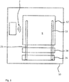
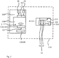
- Fig. 2 depicts a system 110 for mixing and testing a liquid 1 according to another embodiment of the first aspect of the present invention.
- the system 110 is a variant of the system 10 and comprises, preferably consists of, a cartridge 150 and a testing apparatus 160.
- the receiving portion 12 with the first and the second electrode 21, 22 reaching into the receiving portion 12 are integrated into the cartridge 150.
- the cartridge 150 is configured with an inlet 154 which is adapted to receive at least one liquid 1 from outside the cartridge 150 and to conduct the received at least one liquid 1 into the receiving portion 12 150.
- Two or more receiving portions 12 may be provided in a single cartridge 150. Each receiving portion 12 may be provided with its own inlet 154. Alternatively, some or all of the receiving portions 12 may be provided with the liquid 1 to be tested by a single inlet 154 of the cartridge 150.
- One or more piezo-electric elements may be provided for each receiving portion provided in the cartridge.
- the testing apparatus 160 comprises a docking portion 166 adapted to receive the cartridge 150.
- the mixing unit 118 is integrated into the testing apparatus 160.
- the cartridge 150 is adapted to be brought into engagement with the testing apparatus 160, in particular with the docking portion 166 of the testing apparatus 160 such that the mixing unit 118 is positioned to emit the ultrasound waves 2 directed towards the receiving portion 12, or towards all of the receiving portions 12 of the cartridge 150, if there is more than one.
- the mixing unit 118 comprises a frequency generator 40 and at least one piezo-electric element 142, both integrated into the testing apparatus.
- the at least one piezo-electric element 142 is preferably positioned as part of, or adjacent to, a section of the docking portion 166 that is adjacent to the cartridge 150, in particular the receiving portion 12 or all of the receiving portions 12 of the cartridge 150 when the cartridge is brought into engagement with the docking portion 166.
- the mixing unit 118 may comprise a coupling element configured to transport the emitted ultrasound wave from the piezo-electric element 142 to the docking portion 166 and/or to the cartridge 150.
- the docking portion 166 may be configured as a docking bay or a slot or the like in the testing apparatus 160.
- the frequency generator 40 is adapted to generate a periodic electrical signal 41, for example a sine wave, in particular with a frequency of 10 MHz or less.
- the frequency generator 40 is further adapted to apply the generated periodic electric signal 41 to the at least one piezo-electric element 142.
- the piezo-electric element 142 is adapted to emit, when the periodic electrical signal 41 is applied to the piezo-electric element 142, the ultrasound waves towards the receiving portion 12 when the cartridge 150 is brought into engagement with the docking portion 166.
- the piezo-electric element 142 may contain, or consist of, naturally occurring crystals, synthetic crystals like gallium orthophosphate or Langasite or synthetic ceramics.
- Exemplary synthetic ceramics for the piezo-electric element include, but are not limited to, barium titanate, lead zirconate titanate, commonly known as PZT, potassium niobate, lithium niobate, lithium tantalate, sodium tungstate and zinc oxide.
- the cartridge 150 is configured with a first electrical interface 152 which is separately coupled to the first and the second electrodes 21, 22 such as to be able to apply a voltage to the first and the second electrodes 21, 22 and such that the electrical property of the liquid 1 may be determined in response to the applied electrical voltage.
- the testing apparatus 160 is provided with a second electrical interface 162.
- the cartridge 150, the first electrical interface 152, the testing apparatus 160, the second electrical interface 162 and the docking portion 166 are configured such that the first and the second electrical interfaces 152, 162 are brought into electrical connection with each other when the cartridge 150 is brought into engagement with the docking portion 166.
- the voltage application unit 24 and the measuring unit 26, e.g. as described above with respect to the system 10, are integrated into the testing apparatus 160 and are adapted to perform their functions over the electrical connection provided by the first and the second electrical interfaces 152, 162 when they are arranged in electrical connection with each other.
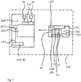
- Fig. 3 shows a system 210 for mixing and testing a liquid 1 according to an example, not according to the invention.
- the system 210 is a variant of the system 110 and differs from the system 110 in the configuration of a mixing unit 218 of the system 210 and of corresponding electrical connections in an apparatus 260 and a cartridge 250 of the system 210. All of the elements of the system 210, or features thereof, not explicitly described as different from the system 10 and/or 110 may be configured in the same way as described for the system 10 and/or 110 or in the foregoing.
- the mixing unit 218 comprises a frequency generator 40 integrated into the testing apparatus 260 as described for the system 110 and the testing apparatus 160.
- the mixing unit 218 further comprises a piezo-electric element 242 integrated into the cartridge 250 as described for the piezo-electric element 142 and the cartridge 150.
- the cartridge 250 is further provided with a third electrical interface 257.
- a docking portion 266 of the testing apparatus 260 is provided with a fourth electrical interface 267.
- the third and the fourth electrical interfaces 257, 267 and the cartridge 250 and the docking portion 266 are configured such that the third and the fourth electrical interfaces 257, 267 are brought into electrical contact with each other when the cartridge 250 is brought into engagement with the docking portion 266 of the testing apparatus 260.
- Signal connections are provided within the testing apparatus 260 and the cartridge 250 such that the periodic electrical signal 41 generated by the frequency generator 40 can be applied to a piezo-electric element 242 over the third and fourth electrical interfaces 257, 267, when the cartridge 150 is brought into engagement with the docking portion 166.
- the piezo-electric element 242 may be configured in the same way as described above with respect to the piezo-electric element 142.
- Figures 4A to 4D depict schematic views of a possible assembly of certain elements of the system according to the first aspect of the present invention, in particular to one of the systems 10, 110 and/or 210 as described above.
- Fig. 4A shows a diagonal top/front/side view
- Fig. 4B a top view
- Fig. 4C a front view
- Fig. 4D a side view of the same assembly of a receiving portion 12', a first and a second electrode 21', 22' a printed circuit board 24 and two piezo-electric elements 44, 46.
- the receiving portion 12' is formed by four wall portions 14' and a bottom portion 16' into which the first and the second electrode 21', 22' reach which are connected to a printed circuit board, PCB, 24.
- the PCB may connect the first and the second electrodes 21', 22' to the voltage application unit 24 and/or to the measuring unit 26.
- Figure 4A to Figure 4D show the assembly of the two piezo-electric elements 44, 46 in close proximity to the receiving portion 12'.
- the piezo-electric elements 44, 46 may be provided together or as alternatives to each other.
- a first piezo-electric element 44 is provided as a strip or cuboid, e.g. consisting of or comprising PZT, with a longitudinal axis of the cuboid parallel to an axial direction of the receiving portion 12' and/or perpendicular to a bottom surface 13 formed by the bottom portion 16' inside the receiving portion 12'.
- a second piezo-electric element 46 is provided as a strip or cuboid, e.g. consisting of or comprising PZT, with a longitudinal axis of the cuboid or strip arranged perpendicular to a normal vector of the surface 13.
- the receiving portion 12' is provided in the form of a hollow cylinder or of a hollow truncated cone, wherein the axial direction of the receiving portion 12' is given by a rotational symmetry axis of the receiving portion 12'.
- the first piezo-electric element 44 and the second piezo-electric element 46 are positioned distanced from said rotational symmetry axis.
- the receiving portion 12' may be configured with a diameter of the hollow cylinder of 8 millimeters or less, preferably five millimeters or less, in particular four millimeters or less.
- the receiving portion may be adapted to hold a maximum volume of 250 mm 3 or less, for example 100 mm 3 or less, preferably 75 mm 3 or less, in particular 60 mm 3 or less.
- the electrodes 21', 22' may be positioned such that there is a distance of 5 millimeters or less between the bottom portion 16' of the receiving portion 12' and the electrodes 21', 22', in particular 3 millimeters or less.
- the electrodes 21', 22' may be positioned distanced from each other in a radial and/or transverse direction with respect to the cylinder. Alternatively, the electrodes 21', 22' may be distanced from each other in an axial direction.
- the electrodes may be provided with a tilt with respect to the rotational symmetry axis or in parallel to the rotational symmetry axis
- Figures 5A to 5D depict schematic views of another possible arrangement of certain elements of the system according to the first aspect of the present invention, in particular to one of the systems 10, 110 and/or 210 as described above.
- Fig. 5A shows a diagonal top/front/side view
- Fig. 5B a top view
- Fig. 5C a front view
- Fig. 5D a side view of the same assembly of a receiving portion 12", a first and a second electrode 21", 22" and a piezo-electric element 44.
- the receiving portion 12" is formed by a cylindrical wall portion 14" and a bottom portion 16" into which the first and the second electrode 21", 22" reach.
- Figure 5A to Figure 5D show the assembly of the piezo-electric element 44, as described above with respect to Figures 4A to 4D and the receiving portion 12', in close proximity to the receiving portion 12".
- the piezo-electric element 44 is provided as a strip or cuboid, e.g. consisting of or comprising PZT, with a longitudinal axis of the cuboid parallel to an axial direction of the receiving portion 12"'.
- the receiving portion 12" is provided in the form of a hollow cylinder, wherein the axial direction of the receiving portion 12" is given by a rotational symmetry axis of the receiving portion 12".
- the piezo-electric element 44 is positioned distanced from said rotational symmetry axis.
- a cross-section of the receiving portion 12", in particular of the volume intended to be occupied by the liquid 1, in a plane perpendicular to the rotational symmetry axis of the receiving portion 12" is smaller than a cross-section of the piezo-electric element 44 in the same plane.
- a diameter of the cylinder of the receiving portion 12" is equal to a width of the piezo-electric element 44.
- a length of the piezo-electric element 44 is smaller than an axial length of the cylinder of the receiving portion 12".
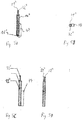
- Fig. 6 shows yet another possible assembly of first and second electrodes 21"', 22'" and a receiving portion 12'" usable in the system according to the first aspect of the present invention, in particular with the systems 10, 110, 210 as described above.
- the receiving portion 12'" is formed as a double-open-ended tube structure through which the first and the second electrodes 21'", 22'" are guided, entering the tube structure on one end and exiting the tube structure on the opposite end, the first and the second electrode 21"', 22'” being provided as wires at, e.g. diametrically opposite, interior sides of the tube structure of the receiving portion 12"'.
- the tube structure 12'" may be formed of plastics, for example of a two-part molded plastic.
- FIG. 6 schematically full blood 3 as a first liquid component and reagents 4 as a second liquid component are depicted as component parts of the liquid 1 that are to be mixed into each other, in particular prior to and/or simultaneous with applying the electrical voltage between the first and the second electrode 21"', 22"'.
- a third liquid component e.g. saline solution and/or additional liquid components may be added to the fluid 1 or as part of the fluid 1 and may be mixed prior to and/or simultaneous with applying the electrical voltage.
- a first piezo-electric element 48-1 and a second piezo-electric element 48-2 are depicted arranged at diametrically opposite sides of the tube structure of the receiving portion 12'" outside the receiving portion 12"'.
- the first and the second piezo-electric elements 48-1, 48-2 may be provided together or as alternatives to each other.
- the first piezo-electric element 48-1 and/or the second piezo-electric element 48-2 may be provided integrated into a cartridge, e.g. the cartridge 150 or 250, comprising the receiving portion 12'" or may be integrated into a testing apparatus, e.g. the testing apparatus 160 or 260, separate from the cartridge comprising the receiving portion 12"'.
- the first piezo-electric element 48-1 may be integrated into the testing apparatus and the second piezo-electric element 48-2 into the cartridge or vice versa.
- the first and second electrodes 21, 22 may be provided as described for the first and second electrodes 21', 22'; 21", 22"; 21"', 22"', the piezo-electric elements 142; 242 may be provided as described for the piezo-electric elements 44, 46, 48-1, 48-2 and/or the receiving portion 12 may be provided as described for the receiving portion 12'; 12"; 12'", as described with respect to Figures 4A to 6 .
- Fig. 7 shows a schematic flow diagram illustrating a method for mixing and testing a liquid 1 according to an embodiment of the second aspect of the present invention.
- This method may be performed with the system according to embodiments of the first aspect of the present invention, in particular with the systems 10; 110; 210 and/or the arrangement variations depicted in Figures 3A-5 .
- the method may be adapted according to any, multiple, or all advantageous modifications and variations of the above embodiments of the system and vice versa.
- a first step S01 the liquid 1 to be tested is provided in a receiving portion 12; 12'; 12"; 12"'.
- ultrasound waves 2 are emitted towards the receiving portion 12; 12'; 12"; 12"'. This is done in order to excite Lamb waves in at least a section 14; 14', 16'; 14", 16"; 16"'-1, 16"'-2 of the receiving portion 12; 12'; 12".
- the emitting S02 is performed, at least also, after the liquid 1 is provided in the receiving portion 12.
- the excited Lamb waves in at least the section 14; 14', 16'; 14", 16"; 16"'-1, 16"'-2 of the receiving portion 12; 12'; 12"; 12'” have the effect of mixing the liquid 1 by inducing mechanical movement and shear forces inside the liquid 1.
- the liquid 1 may comprise, or consist of, a first liquid component 3, in particular full blood or containing blood platelets and a second liquid component 4, in particular saline solution and/or reagents.
- the reagents preferably are reagents affecting blood coagulation.
- a first electrode 21; 21'; 21"; 21'" and a second electrode 22; 22'; 22"; 22'" are brought into contact with the liquid 1 in the receiving portion 12; 12'; 12"; 12"'.
- the first and the second electrode 21; 21'; 21"; 21"', 22; 22'; 22'; 22'" may be fixedly arranged with respect to the receiving portion 12; 12'; 12"; 12'" such that the providing S03 of the contact between the first electrode and the second electrode 21, 22; 21', 22'; 21", 22"; 22", 22'” and the liquid 1 is performed by way of the providing S01 of the liquid 1 in the receiving portion 12; 12'; 12"; 12"', for example after the liquid 1 has achieved a certain liquid level inside the receiving portion 12; 12'; 12"; 12"'.
- This liquid level at which the contact is formed may e.g. be five millimeters or less, preferably three millimeters or less, from the bottom portion 16' of the receiving
- a step S04 an electrical voltage is applied between the first electrode 21; 21'; 21"; 212'" and the second electrode 22; 22'; 22"; 22'" in contact with the liquid 1.
- an alternating voltage is applied.
- a step S05 an electrical property of the fluid 1 in a receiving portion 12; 12'; 12"; 12'" is measured in response to the applied electrical voltage.
- an impedance of the fluid 1 is measured in response to the applied alternating electrical voltage.
- Fig. 8 shows a schematic flow diagram of a method for mixing and testing a liquid 1 according to another embodiment of the second aspect of the present invention which is a variant of the method described with respect to Fig. 6 .
- the method of Fig. 7 differs from the method of Fig. 6 in that, in particular, the step of emitting S02 the ultrasound waves comprises a first sub-step S21 and a second sub-step S22.
- the first sub-step S21 a periodic electrical signal 41 with a frequency of 10 MHz or less is generated, for example with the frequency generator 40 of the system 110, 210 as described above.
- the generated periodic electrical signal 41 is applied to at least one piezo-electric element 142; 242; 44; 46; 48-1; 48-2.
- the piezo-electric element 142; 242; 44; 46; 48-1; 48-2 is adapted to emit the ultrasound waves 2 towards the receiving portion 12; 12'; 12"; 12'" when the periodic electrical signal 41 is applied.
- a property of the fluid 1, in particular a property relating to blood or blood platelets within the fluid 1, is determined based on the measured electrical property of the fluid 1.
- an analyzing unit may be provided within the system according to the first aspect of the present invention, in particular within the testing apparatus 150; 250 of the system 110; 210.
Landscapes
- Health & Medical Sciences (AREA)
- Life Sciences & Earth Sciences (AREA)
- Chemical & Material Sciences (AREA)
- Physics & Mathematics (AREA)
- Engineering & Computer Science (AREA)
- Biomedical Technology (AREA)
- Pathology (AREA)
- Immunology (AREA)
- General Physics & Mathematics (AREA)
- General Health & Medical Sciences (AREA)
- Biochemistry (AREA)
- Analytical Chemistry (AREA)
- Hematology (AREA)
- Chemical Kinetics & Catalysis (AREA)
- Medicinal Chemistry (AREA)
- Food Science & Technology (AREA)
- Ecology (AREA)
- Urology & Nephrology (AREA)
- Molecular Biology (AREA)
- Biophysics (AREA)
- Electrochemistry (AREA)
- Automatic Analysis And Handling Materials Therefor (AREA)
Claims (13)
- System (110) zum Mischen und Prüfen einer Flüssigkeit (1), wobei es eine Kartusche (150) und ein Prüfgerät (160) umfasst;
wobei die Kartusche (150) Folgendes umfasst:einen aufnehmenden Abschnitt (12; 12'; 12", 12"'), um eine zu prüfende Flüssigkeit (1) aufzunehmen;mindestens eine erste Elektrode (21; 21'; 21"; 21"'), die in den aufnehmenden Abschnitt (12; 12'; 12", 12"') hineinreicht, und eine zweite Elektrode (22; 22'; 22"; 22'''), die in den aufnehmenden Abschnitt (12; 12'; 12", 12"') hineinreicht, wobei der aufnehmende Abschnitt (12; 12'; 12", 12"') sowie die erste und die zweite Elektrode (21, 22; 21', 22'; 21", 22"; 21"', 22"') in die Kartusche (150) eingebaut sind;wobei das Prüfgerät (160) Folgendes umfasst:wobei die Kartusche (150) dafür geeignet ist, mit dem Prüfgerät (160) in Eingriff gebracht zu werden, sodass die Mischeinheit (118) derart angeordnet ist, dass sie die Ultraschallwellen (2) in Richtung des aufnehmenden Abschnitts (12; 12'; 12", 12"') aussendet);eine Mischeinheit (118), die dafür geeignet ist, Ultraschallwellen (2) in Richtung des aufnehmenden Abschnitts (12; 12'; 12", 12"') auszusenden, um zumindest in einem Teilbereich (14; 14', 16'; 14", 16"; 16"'-1, 16"'-2) des aufnehmenden Abschnitts (12; 12'; 12", 12"') Lamb-Wellen anzuregen, wobei die Mischeinheit (118) in das Prüfgerät (160) eingebaut ist.
eine Einheit (24) zum Anlegen einer Spannung, die dafür geeignet ist, eine elektrische Spannung zwischen der ersten Elektrode (21; 21'; 21"; 21"') und der zweiten Elektrode (22; 22'; 22"; 22"') anzulegen; und eine Messeinheit (26), die dafür geeignet ist, eine elektrische Eigenschaft des Fluids (1) als Antwort auf die angelegte elektrische Spannung zu bestimmen. - System (110) nach Anspruch 1,
wobei die Kartusche (150) eine erste elektrische Schnittstelle (152) umfasst; wobei das Prüfgerät (160) eine zweite elektrische Schnittstelle (162) umfasst; wobei die Einheit (24) zum Anlegen einer Spannung in das Prüfgerät (160) eingebaut ist und dafür geeignet ist, über die erste und die zweite elektrische Schnittstelle (152, 162) die elektrische Spannung an die erste und die zweite Elektrode (21, 22; 21', 22'; 21", 22"; 21"', 22"') anzulegen, wenn die Kartusche (150) mit dem Prüfgerät (160) in Eingriff gebracht wird. - System (110) nach Anspruch 1 oder 2,
wobei die Kartusche (150) eine erste elektrische Schnittstelle (152) umfasst; wobei das Prüfgerät (160) eine zweite elektrische Schnittstelle (162) umfasst; wobei die Messeinheit (26) in das Prüfgerät (160) eingebaut ist und wobei die Messeinheit (26) über die erste und die zweite elektrische Schnittstelle (152, 162) elektrisch an die erste und die zweite Elektrode (21, 22; 21', 22'; 21", 22"; 21"', 22"') gekoppelt wird, wenn die Kartusche (150) mit dem Prüfgerät (160) in Eingriff gebracht wird. - System (110) nach beliebigen der Ansprüche 1 bis 3, wobei die Mischeinheit (118) mindestens ein piezoelektrisches Element (142; 242; 44; 46; 48-1; 48-2) umfasst sowie einen Frequenzgenerator (40), der dafür geeignet ist, ein periodisches elektrisches Signal (41) zu erzeugen, das dafür bestimmt es, an das mindestens eine piezoelektrische Element (142; 242; 44; 46; 48-1; 48-2) angelegt zu werden, sodass das mindestens eine piezoelektrische Element (142; 242; 44; 46; 48-1; 48-2) die Ultraschallwellen (2) in Richtung des aufnehmenden Abschnitts (12; 12'; 12", 12"') aussendet.
- System (110) nach Anspruch 4, wobei der Frequenzgenerator (40) derart ausgelegt ist, dass das periodische elektrische Signal (41) mit einer Frequenz von zehn Megahertz oder weniger erzeugt und an das mindestens eine piezoelektrische Element (142; 242; 44; 46; 48-1; 48-2) angelegt wird.
- System (110) nach beliebigen der Ansprüche 1 bis 5,
wobei der aufnehmende Abschnitt (12"') als Röhrenstruktur mit doppelt offenen Enden ausgebildet ist; und wobei die Mischeinheit (18; 118; 218) dafür geeignet ist, die Ultraschallwellen (2) in Richtung eines Wandabschnitts (16"'-1, 16"'-2) der Röhrenstruktur auszusenden. - System (110) nach beliebigen der Ansprüche 1 bis 6,
wobei die Einheit (24) zum Anlegen einer Spannung dafür geeignet ist, zwischen der ersten Elektrode (21; 21'; 21"; 21"') und der zweiten Elektrode (22; 22'; 22"; 22"') eine Wechselspannung anzulegen; und wobei die Messeinheit (26) dafür geeignet ist, als Antwort auf die angelegte Wechselspannung eine Impedanz des Fluids (1) zu bestimmen. - System (110) nach beliebigen der Ansprüche 1 bis 7,
wobei der aufnehmende Abschnitt (12; 12'; 12", 12"') dafür geeignet ist, ein Maximalvolumen von zweihundertfünfzig Kubikmillimetern oder weniger zu fassen. - Verfahren zum Mischen und Prüfen einer Flüssigkeit (1) unter Verwendung des Systems (110) mit der Kartusche (150) und dem Prüfgerät (160) nach beliebigen der Ansprüche 1 bis 8, wobei es die folgenden Schritte umfasst:Bereitstellen (S01) der zu prüfenden Flüssigkeit (1) in einem aufnehmenden Abschnitt (12; 12'; 12", 12"');Aussenden (S02) von Ultraschallwellen (2) in Richtung des aufnehmenden Abschnitts (12; 12'; 12", 12"'), um zumindest in einem Teilbereich (14; 14', 16'; 14", 16"; 16"'-1, 16"'-2) des aufnehmenden Abschnitts (12; 12'; 12") Lamb-Wellen anzuregen, nachdem die Flüssigkeit (1) in dem aufnehmenden Abschnitt (12) bereitgestellt wurde;Bereitstellen (S03) einer ersten Elektrode (21; 21'; 21"; 21"') und einer zweiten Elektrode (22; 22'; 22"; 22"'), die mit der Flüssigkeit (1) im aufnehmenden Abschnitt (12; 12'; 12", 12"') in Kontakt sind;Anlegen (S04) einer elektrischen Spannung zwischen der ersten Elektrode (21; 21'; 21"; 21"') und der zweiten Elektrode (22; 22'; 22"; 22'''), die mit der Flüssigkeit (1) in Kontakt sind; undMessen (S05) einer elektrischen Eigenschaft des Fluids (1) in dem aufnehmenden Abschnitt (12; 12'; 12", 12"') als Antwort auf die angelegte elektrische Spannung.
- Verfahren nach Anspruch 9,
wobei das Aussenden (S02) der Ultraschallwellen (2) Folgendes umfasst:Erzeugen (S21) eines periodischen elektrischen Signals (41) mit einer Frequenz von zehn Megahertz oder weniger;Anlegen (S22) des erzeugten periodischen elektrischen Signals (41) an mindestens ein piezoelektrisches Element (142; 242; 44; 46; 48-1; 48-2). - Verfahren nach Anspruch 9 oder 10,
wobei an die erste Elektrode (21; 21'; 21"; 21"') und die zweite Elektrode (22; 22'; 22"; 22"') eine Wechselspannung angelegt wird; und
wobei als Antwort auf die angelegte Wechselspannung eine Impedanz des Fluids (1) bestimmt wird. - Verfahren nach Anspruch 11,
wobei die Impedanz des Fluids (1), welche als Antwort auf die angelegte Wechselspannung auftritt, kontinuierlich über einen vorbestimmten Messzeitraum gemessen wird. - Verfahren nach beliebigen der Ansprüche 9 bis 12,
wobei die Flüssigkeit (1) einen ersten Flüssigkeitsbestandteil (3), der Blutplättchen beinhaltet, und einen zweiten Flüssigkeitsbestandteil (4) umfasst oder aus diesen besteht;
und wobei das Aussenden (S02) von Ultraschallwellen (2) über einen vorbestimmten Aussendezeitraum erfolgt, um den ersten Flüssigkeitsbestandteil (3) mit dem zweiten Flüssigkeitsbestandteil (4) zu mischen.
Priority Applications (3)
| Application Number | Priority Date | Filing Date | Title |
|---|---|---|---|
| EP19151809.1A EP3489668B1 (de) | 2015-11-25 | 2015-11-25 | Vorrichtung zur mischung und zum testen einer flüssigkeit |
| ES15196214T ES2717112T3 (es) | 2015-11-25 | 2015-11-25 | Sistema y procedimiento para mezclar y analizar un líquido |
| EP15196214.9A EP3173776B1 (de) | 2015-11-25 | 2015-11-25 | Vorrichtung und verfahren zur mischung und zum testen einer flüssigkeit |
Applications Claiming Priority (1)
| Application Number | Priority Date | Filing Date | Title |
|---|---|---|---|
| EP15196214.9A EP3173776B1 (de) | 2015-11-25 | 2015-11-25 | Vorrichtung und verfahren zur mischung und zum testen einer flüssigkeit |
Related Child Applications (1)
| Application Number | Title | Priority Date | Filing Date |
|---|---|---|---|
| EP19151809.1A Division EP3489668B1 (de) | 2015-11-25 | 2015-11-25 | Vorrichtung zur mischung und zum testen einer flüssigkeit |
Publications (2)
| Publication Number | Publication Date |
|---|---|
| EP3173776A1 EP3173776A1 (de) | 2017-05-31 |
| EP3173776B1 true EP3173776B1 (de) | 2019-01-16 |
Family
ID=54705062
Family Applications (2)
| Application Number | Title | Priority Date | Filing Date |
|---|---|---|---|
| EP19151809.1A Active EP3489668B1 (de) | 2015-11-25 | 2015-11-25 | Vorrichtung zur mischung und zum testen einer flüssigkeit |
| EP15196214.9A Active EP3173776B1 (de) | 2015-11-25 | 2015-11-25 | Vorrichtung und verfahren zur mischung und zum testen einer flüssigkeit |
Family Applications Before (1)
| Application Number | Title | Priority Date | Filing Date |
|---|---|---|---|
| EP19151809.1A Active EP3489668B1 (de) | 2015-11-25 | 2015-11-25 | Vorrichtung zur mischung und zum testen einer flüssigkeit |
Country Status (2)
| Country | Link |
|---|---|
| EP (2) | EP3489668B1 (de) |
| ES (1) | ES2717112T3 (de) |
Family Cites Families (10)
| Publication number | Priority date | Publication date | Assignee | Title |
|---|---|---|---|---|
| FR2664981B1 (fr) * | 1990-07-20 | 1994-04-29 | Serbio | Dispositif de detection du changement de viscosite d'un electrolyte liquide par effet de depolarisation. |
| US5639423A (en) * | 1992-08-31 | 1997-06-17 | The Regents Of The University Of Calfornia | Microfabricated reactor |
| US6004818A (en) * | 1997-08-07 | 1999-12-21 | Chrono-Log Corporation | Aggregometer with disposable test cell |
| US6413783B1 (en) * | 1997-09-18 | 2002-07-02 | Meso Scale Technologies, Llc | Assay sonication apparatus and methodology |
| JP2001188070A (ja) * | 1999-12-28 | 2001-07-10 | Hitachi Ltd | 自動分析装置及び自動分析方法 |
| DE10013377A1 (de) * | 2000-03-17 | 2001-09-20 | Dade Behring Marburg Gmbh | Induzierte Aggregation und Agglutination von Plättchen |
| ES2340378T3 (es) * | 2003-12-16 | 2010-06-02 | Dynabyte Informationssysteme Gmbh | Dispositivo de cartucho para el analisis de sangre. |
| JP2005319407A (ja) * | 2004-05-10 | 2005-11-17 | Hitachi Ltd | 圧電デバイスを用いた機器 |
| US20060024206A1 (en) * | 2004-07-29 | 2006-02-02 | Sinha Naveen N | Non-invasive acoustic technique for mixing and segregation of fluid suspensions in microfluidic applications |
| EP2112508B1 (de) * | 2008-04-22 | 2010-10-13 | Holger Behnk | Aggregometer |
-
2015
- 2015-11-25 ES ES15196214T patent/ES2717112T3/es active Active
- 2015-11-25 EP EP19151809.1A patent/EP3489668B1/de active Active
- 2015-11-25 EP EP15196214.9A patent/EP3173776B1/de active Active
Non-Patent Citations (1)
| Title |
|---|
| None * |
Also Published As
| Publication number | Publication date |
|---|---|
| ES2717112T3 (es) | 2019-06-19 |
| EP3173776A1 (de) | 2017-05-31 |
| EP3489668A1 (de) | 2019-05-29 |
| EP3489668B1 (de) | 2023-03-22 |
Similar Documents
| Publication | Publication Date | Title |
|---|---|---|
| Connacher et al. | Micro/nano acoustofluidics: materials, phenomena, design, devices, and applications | |
| Hammarström et al. | Non-contact acoustic cell trapping in disposable glass capillaries | |
| US7108137B2 (en) | Method and apparatus for separating particles by size | |
| US8448496B2 (en) | Piezoelectric coagulation sensors | |
| CN101952693A (zh) | 检测移液管状态的方法,吸移方法,吸移设备和吸移设备的吸入管 | |
| WO2021256027A1 (ja) | 自動化学分析装置および電気インピーダンススペクトル測定器 | |
| EP2097745B1 (de) | Biosensor | |
| JP4925819B2 (ja) | ミクロキャビティでの少量液体の混合方法と装置 | |
| US11426727B2 (en) | Acoustophoretic lysis devices and methods | |
| CN115468916B (zh) | 片上流体操控模块、声流体芯片及分析装置 | |
| JP2010522870A5 (de) | ||
| WO2005107939A1 (ja) | 圧電デバイスを用いた機器 | |
| WO2021182143A1 (en) | Liquid droplet discharging method, method for manufacturing container including tissue body, and liquid droplet discharging apparatus | |
| CN112191284A (zh) | 微流控超声电化学片上实验室分析平台 | |
| KR20230034202A (ko) | 세포 용해 시스템 및 방법 | |
| EP3173776B1 (de) | Vorrichtung und verfahren zur mischung und zum testen einer flüssigkeit | |
| EP1604741A1 (de) | Verfahren und Vorrichtung zur Ausgabe von Flüssigkeiten mit einem Pipettiernadel | |
| CN104056708B (zh) | 基于声表面波的细胞粉碎器 | |
| EP1912072A1 (de) | Mischvorrichtung und analysevorrichtung mit der mischvorrichtung | |
| KR101953012B1 (ko) | 챔버 소자, 상기 챔버 소자를 포함하는 혈액 검사 장치 및 상기 혈액 검사 장치의 제조 방법 | |
| US20090267448A1 (en) | Device for mixing fluids | |
| Zhang et al. | Hundred-micron droplet ejection by focused ultrasound for genomic applications | |
| ES3058041T3 (en) | Apparatus for addressing wells within a microarray plate | |
| JP2008268079A (ja) | 液面検知装置及び自動分析装置 | |
| EP3281004A1 (de) | Vorrichtung und verfahren zur messung der physikalischen eigenschaften eines materials |
Legal Events
| Date | Code | Title | Description |
|---|---|---|---|
| PUAI | Public reference made under article 153(3) epc to a published international application that has entered the european phase |
Free format text: ORIGINAL CODE: 0009012 |
|
| STAA | Information on the status of an ep patent application or granted ep patent |
Free format text: STATUS: THE APPLICATION HAS BEEN PUBLISHED |
|
| AK | Designated contracting states |
Kind code of ref document: A1 Designated state(s): AL AT BE BG CH CY CZ DE DK EE ES FI FR GB GR HR HU IE IS IT LI LT LU LV MC MK MT NL NO PL PT RO RS SE SI SK SM TR |
|
| AX | Request for extension of the european patent |
Extension state: BA ME |
|
| STAA | Information on the status of an ep patent application or granted ep patent |
Free format text: STATUS: REQUEST FOR EXAMINATION WAS MADE |
|
| 17P | Request for examination filed |
Effective date: 20171130 |
|
| RBV | Designated contracting states (corrected) |
Designated state(s): AL AT BE BG CH CY CZ DE DK EE ES FI FR GB GR HR HU IE IS IT LI LT LU LV MC MK MT NL NO PL PT RO RS SE SI SK SM TR |
|
| GRAP | Despatch of communication of intention to grant a patent |
Free format text: ORIGINAL CODE: EPIDOSNIGR1 |
|
| STAA | Information on the status of an ep patent application or granted ep patent |
Free format text: STATUS: GRANT OF PATENT IS INTENDED |
|
| INTG | Intention to grant announced |
Effective date: 20180731 |
|
| RAP1 | Party data changed (applicant data changed or rights of an application transferred) |
Owner name: C A CASYSO GMBH |
|
| GRAS | Grant fee paid |
Free format text: ORIGINAL CODE: EPIDOSNIGR3 |
|
| GRAA | (expected) grant |
Free format text: ORIGINAL CODE: 0009210 |
|
| STAA | Information on the status of an ep patent application or granted ep patent |
Free format text: STATUS: THE PATENT HAS BEEN GRANTED |
|
| AK | Designated contracting states |
Kind code of ref document: B1 Designated state(s): AL AT BE BG CH CY CZ DE DK EE ES FI FR GB GR HR HU IE IS IT LI LT LU LV MC MK MT NL NO PL PT RO RS SE SI SK SM TR |
|
| REG | Reference to a national code |
Ref country code: GB Ref legal event code: FG4D |
|
| REG | Reference to a national code |
Ref country code: CH Ref legal event code: EP |
|
| REG | Reference to a national code |
Ref country code: IE Ref legal event code: FG4D |
|
| REG | Reference to a national code |
Ref country code: DE Ref legal event code: R096 Ref document number: 602015023551 Country of ref document: DE |
|
| REG | Reference to a national code |
Ref country code: AT Ref legal event code: REF Ref document number: 1090070 Country of ref document: AT Kind code of ref document: T Effective date: 20190215 |
|
| REG | Reference to a national code |
Ref country code: SE Ref legal event code: TRGR |
|
| REG | Reference to a national code |
Ref country code: NL Ref legal event code: FP |
|
| REG | Reference to a national code |
Ref country code: LT Ref legal event code: MG4D |
|
| REG | Reference to a national code |
Ref country code: ES Ref legal event code: FG2A Ref document number: 2717112 Country of ref document: ES Kind code of ref document: T3 Effective date: 20190619 |
|
| REG | Reference to a national code |
Ref country code: AT Ref legal event code: MK05 Ref document number: 1090070 Country of ref document: AT Kind code of ref document: T Effective date: 20190116 |
|
| PG25 | Lapsed in a contracting state [announced via postgrant information from national office to epo] |
Ref country code: PL Free format text: LAPSE BECAUSE OF FAILURE TO SUBMIT A TRANSLATION OF THE DESCRIPTION OR TO PAY THE FEE WITHIN THE PRESCRIBED TIME-LIMIT Effective date: 20190116 Ref country code: LT Free format text: LAPSE BECAUSE OF FAILURE TO SUBMIT A TRANSLATION OF THE DESCRIPTION OR TO PAY THE FEE WITHIN THE PRESCRIBED TIME-LIMIT Effective date: 20190116 Ref country code: FI Free format text: LAPSE BECAUSE OF FAILURE TO SUBMIT A TRANSLATION OF THE DESCRIPTION OR TO PAY THE FEE WITHIN THE PRESCRIBED TIME-LIMIT Effective date: 20190116 Ref country code: PT Free format text: LAPSE BECAUSE OF FAILURE TO SUBMIT A TRANSLATION OF THE DESCRIPTION OR TO PAY THE FEE WITHIN THE PRESCRIBED TIME-LIMIT Effective date: 20190516 Ref country code: NO Free format text: LAPSE BECAUSE OF FAILURE TO SUBMIT A TRANSLATION OF THE DESCRIPTION OR TO PAY THE FEE WITHIN THE PRESCRIBED TIME-LIMIT Effective date: 20190416 |
|
| PG25 | Lapsed in a contracting state [announced via postgrant information from national office to epo] |
Ref country code: HR Free format text: LAPSE BECAUSE OF FAILURE TO SUBMIT A TRANSLATION OF THE DESCRIPTION OR TO PAY THE FEE WITHIN THE PRESCRIBED TIME-LIMIT Effective date: 20190116 Ref country code: BG Free format text: LAPSE BECAUSE OF FAILURE TO SUBMIT A TRANSLATION OF THE DESCRIPTION OR TO PAY THE FEE WITHIN THE PRESCRIBED TIME-LIMIT Effective date: 20190416 Ref country code: RS Free format text: LAPSE BECAUSE OF FAILURE TO SUBMIT A TRANSLATION OF THE DESCRIPTION OR TO PAY THE FEE WITHIN THE PRESCRIBED TIME-LIMIT Effective date: 20190116 Ref country code: LV Free format text: LAPSE BECAUSE OF FAILURE TO SUBMIT A TRANSLATION OF THE DESCRIPTION OR TO PAY THE FEE WITHIN THE PRESCRIBED TIME-LIMIT Effective date: 20190116 Ref country code: IS Free format text: LAPSE BECAUSE OF FAILURE TO SUBMIT A TRANSLATION OF THE DESCRIPTION OR TO PAY THE FEE WITHIN THE PRESCRIBED TIME-LIMIT Effective date: 20190516 Ref country code: GR Free format text: LAPSE BECAUSE OF FAILURE TO SUBMIT A TRANSLATION OF THE DESCRIPTION OR TO PAY THE FEE WITHIN THE PRESCRIBED TIME-LIMIT Effective date: 20190417 |
|
| REG | Reference to a national code |
Ref country code: DE Ref legal event code: R097 Ref document number: 602015023551 Country of ref document: DE |
|
| PG25 | Lapsed in a contracting state [announced via postgrant information from national office to epo] |
Ref country code: AL Free format text: LAPSE BECAUSE OF FAILURE TO SUBMIT A TRANSLATION OF THE DESCRIPTION OR TO PAY THE FEE WITHIN THE PRESCRIBED TIME-LIMIT Effective date: 20190116 Ref country code: DK Free format text: LAPSE BECAUSE OF FAILURE TO SUBMIT A TRANSLATION OF THE DESCRIPTION OR TO PAY THE FEE WITHIN THE PRESCRIBED TIME-LIMIT Effective date: 20190116 Ref country code: AT Free format text: LAPSE BECAUSE OF FAILURE TO SUBMIT A TRANSLATION OF THE DESCRIPTION OR TO PAY THE FEE WITHIN THE PRESCRIBED TIME-LIMIT Effective date: 20190116 Ref country code: SK Free format text: LAPSE BECAUSE OF FAILURE TO SUBMIT A TRANSLATION OF THE DESCRIPTION OR TO PAY THE FEE WITHIN THE PRESCRIBED TIME-LIMIT Effective date: 20190116 Ref country code: EE Free format text: LAPSE BECAUSE OF FAILURE TO SUBMIT A TRANSLATION OF THE DESCRIPTION OR TO PAY THE FEE WITHIN THE PRESCRIBED TIME-LIMIT Effective date: 20190116 Ref country code: CZ Free format text: LAPSE BECAUSE OF FAILURE TO SUBMIT A TRANSLATION OF THE DESCRIPTION OR TO PAY THE FEE WITHIN THE PRESCRIBED TIME-LIMIT Effective date: 20190116 Ref country code: RO Free format text: LAPSE BECAUSE OF FAILURE TO SUBMIT A TRANSLATION OF THE DESCRIPTION OR TO PAY THE FEE WITHIN THE PRESCRIBED TIME-LIMIT Effective date: 20190116 |
|
| PLBE | No opposition filed within time limit |
Free format text: ORIGINAL CODE: 0009261 |
|
| STAA | Information on the status of an ep patent application or granted ep patent |
Free format text: STATUS: NO OPPOSITION FILED WITHIN TIME LIMIT |
|
| PG25 | Lapsed in a contracting state [announced via postgrant information from national office to epo] |
Ref country code: SM Free format text: LAPSE BECAUSE OF FAILURE TO SUBMIT A TRANSLATION OF THE DESCRIPTION OR TO PAY THE FEE WITHIN THE PRESCRIBED TIME-LIMIT Effective date: 20190116 |
|
| 26N | No opposition filed |
Effective date: 20191017 |
|
| PG25 | Lapsed in a contracting state [announced via postgrant information from national office to epo] |
Ref country code: SI Free format text: LAPSE BECAUSE OF FAILURE TO SUBMIT A TRANSLATION OF THE DESCRIPTION OR TO PAY THE FEE WITHIN THE PRESCRIBED TIME-LIMIT Effective date: 20190116 |
|
| PG25 | Lapsed in a contracting state [announced via postgrant information from national office to epo] |
Ref country code: TR Free format text: LAPSE BECAUSE OF FAILURE TO SUBMIT A TRANSLATION OF THE DESCRIPTION OR TO PAY THE FEE WITHIN THE PRESCRIBED TIME-LIMIT Effective date: 20190116 |
|
| REG | Reference to a national code |
Ref country code: CH Ref legal event code: PL |
|
| PG25 | Lapsed in a contracting state [announced via postgrant information from national office to epo] |
Ref country code: LU Free format text: LAPSE BECAUSE OF NON-PAYMENT OF DUE FEES Effective date: 20191125 Ref country code: MC Free format text: LAPSE BECAUSE OF FAILURE TO SUBMIT A TRANSLATION OF THE DESCRIPTION OR TO PAY THE FEE WITHIN THE PRESCRIBED TIME-LIMIT Effective date: 20190116 Ref country code: CH Free format text: LAPSE BECAUSE OF NON-PAYMENT OF DUE FEES Effective date: 20191130 Ref country code: LI Free format text: LAPSE BECAUSE OF NON-PAYMENT OF DUE FEES Effective date: 20191130 |
|
| REG | Reference to a national code |
Ref country code: BE Ref legal event code: MM Effective date: 20191130 |
|
| PG25 | Lapsed in a contracting state [announced via postgrant information from national office to epo] |
Ref country code: IE Free format text: LAPSE BECAUSE OF NON-PAYMENT OF DUE FEES Effective date: 20191125 |
|
| PG25 | Lapsed in a contracting state [announced via postgrant information from national office to epo] |
Ref country code: BE Free format text: LAPSE BECAUSE OF NON-PAYMENT OF DUE FEES Effective date: 20191130 |
|
| PG25 | Lapsed in a contracting state [announced via postgrant information from national office to epo] |
Ref country code: CY Free format text: LAPSE BECAUSE OF FAILURE TO SUBMIT A TRANSLATION OF THE DESCRIPTION OR TO PAY THE FEE WITHIN THE PRESCRIBED TIME-LIMIT Effective date: 20190116 |
|
| PG25 | Lapsed in a contracting state [announced via postgrant information from national office to epo] |
Ref country code: MT Free format text: LAPSE BECAUSE OF FAILURE TO SUBMIT A TRANSLATION OF THE DESCRIPTION OR TO PAY THE FEE WITHIN THE PRESCRIBED TIME-LIMIT Effective date: 20190116 Ref country code: HU Free format text: LAPSE BECAUSE OF FAILURE TO SUBMIT A TRANSLATION OF THE DESCRIPTION OR TO PAY THE FEE WITHIN THE PRESCRIBED TIME-LIMIT; INVALID AB INITIO Effective date: 20151125 |
|
| PG25 | Lapsed in a contracting state [announced via postgrant information from national office to epo] |
Ref country code: MK Free format text: LAPSE BECAUSE OF FAILURE TO SUBMIT A TRANSLATION OF THE DESCRIPTION OR TO PAY THE FEE WITHIN THE PRESCRIBED TIME-LIMIT Effective date: 20190116 |
|
| P01 | Opt-out of the competence of the unified patent court (upc) registered |
Effective date: 20230524 |
|
| PGFP | Annual fee paid to national office [announced via postgrant information from national office to epo] |
Ref country code: NL Payment date: 20251126 Year of fee payment: 11 |
|
| PGFP | Annual fee paid to national office [announced via postgrant information from national office to epo] |
Ref country code: DE Payment date: 20251128 Year of fee payment: 11 |
|
| PGFP | Annual fee paid to national office [announced via postgrant information from national office to epo] |
Ref country code: GB Payment date: 20251127 Year of fee payment: 11 |
|
| PGFP | Annual fee paid to national office [announced via postgrant information from national office to epo] |
Ref country code: IT Payment date: 20251119 Year of fee payment: 11 |
|
| PGFP | Annual fee paid to national office [announced via postgrant information from national office to epo] |
Ref country code: FR Payment date: 20251125 Year of fee payment: 11 |
|
| PGFP | Annual fee paid to national office [announced via postgrant information from national office to epo] |
Ref country code: SE Payment date: 20251127 Year of fee payment: 11 |
|
| PGFP | Annual fee paid to national office [announced via postgrant information from national office to epo] |
Ref country code: ES Payment date: 20251201 Year of fee payment: 11 |