EP3174149B1 - Batterie mit elektrolytlösungszirkulation - Google Patents
Batterie mit elektrolytlösungszirkulation Download PDFInfo
- Publication number
- EP3174149B1 EP3174149B1 EP15824820.3A EP15824820A EP3174149B1 EP 3174149 B1 EP3174149 B1 EP 3174149B1 EP 15824820 A EP15824820 A EP 15824820A EP 3174149 B1 EP3174149 B1 EP 3174149B1
- Authority
- EP
- European Patent Office
- Prior art keywords
- gas
- pressure adjustment
- pressure
- phase portion
- gas phase
- Prior art date
- Legal status (The legal status is an assumption and is not a legal conclusion. Google has not performed a legal analysis and makes no representation as to the accuracy of the status listed.)
- Active
Links
Images

Classifications
-
- H—ELECTRICITY
- H01—ELECTRIC ELEMENTS
- H01M—PROCESSES OR MEANS, e.g. BATTERIES, FOR THE DIRECT CONVERSION OF CHEMICAL ENERGY INTO ELECTRICAL ENERGY
- H01M8/00—Fuel cells; Manufacture thereof
- H01M8/04—Auxiliary arrangements, e.g. for control of pressure or for circulation of fluids
- H01M8/04082—Arrangements for control of reactant parameters, e.g. pressure or concentration
- H01M8/04201—Reactant storage and supply, e.g. means for feeding, pipes
-
- H—ELECTRICITY
- H01—ELECTRIC ELEMENTS
- H01M—PROCESSES OR MEANS, e.g. BATTERIES, FOR THE DIRECT CONVERSION OF CHEMICAL ENERGY INTO ELECTRICAL ENERGY
- H01M8/00—Fuel cells; Manufacture thereof
- H01M8/04—Auxiliary arrangements, e.g. for control of pressure or for circulation of fluids
-
- H—ELECTRICITY
- H01—ELECTRIC ELEMENTS
- H01M—PROCESSES OR MEANS, e.g. BATTERIES, FOR THE DIRECT CONVERSION OF CHEMICAL ENERGY INTO ELECTRICAL ENERGY
- H01M8/00—Fuel cells; Manufacture thereof
- H01M8/18—Regenerative fuel cells, e.g. redox flow batteries or secondary fuel cells
-
- H—ELECTRICITY
- H01—ELECTRIC ELEMENTS
- H01M—PROCESSES OR MEANS, e.g. BATTERIES, FOR THE DIRECT CONVERSION OF CHEMICAL ENERGY INTO ELECTRICAL ENERGY
- H01M8/00—Fuel cells; Manufacture thereof
- H01M8/18—Regenerative fuel cells, e.g. redox flow batteries or secondary fuel cells
- H01M8/184—Regeneration by electrochemical means
- H01M8/188—Regeneration by electrochemical means by recharging of redox couples containing fluids; Redox flow type batteries
-
- Y—GENERAL TAGGING OF NEW TECHNOLOGICAL DEVELOPMENTS; GENERAL TAGGING OF CROSS-SECTIONAL TECHNOLOGIES SPANNING OVER SEVERAL SECTIONS OF THE IPC; TECHNICAL SUBJECTS COVERED BY FORMER USPC CROSS-REFERENCE ART COLLECTIONS [XRACs] AND DIGESTS
- Y02—TECHNOLOGIES OR APPLICATIONS FOR MITIGATION OR ADAPTATION AGAINST CLIMATE CHANGE
- Y02E—REDUCTION OF GREENHOUSE GAS [GHG] EMISSIONS, RELATED TO ENERGY GENERATION, TRANSMISSION OR DISTRIBUTION
- Y02E60/00—Enabling technologies; Technologies with a potential or indirect contribution to GHG emissions mitigation
- Y02E60/30—Hydrogen technology
- Y02E60/50—Fuel cells
Definitions
- the present invention relates to an electrolytic solution circulation type battery such as a redox flow battery. More particularly, the invention relates to an electrolytic solution circulation type battery including a pressure adjustment mechanism having excellent maintainability and an electrolytic solution circulation type battery in which the pressure adjustable range inside the tank is wide.
- An electrolytic solution circulation type battery such as a redox flow battery (RF battery) is a large-capacity storage battery that stores power derived from natural energy obtained by photovoltaic power generation, wind power generation, or the like.
- An RF battery which is typically connected, through an AC/DC converter, between a power generation unit (such as photovoltaic power generating equipment, wind power generation equipment, or a general power plant) and a load (such as a consumer), charges and stores electricity generated by the power generation unit and discharges and supplies stored electricity to the load.
- a power generation unit such as photovoltaic power generating equipment, wind power generation equipment, or a general power plant
- a load such as a consumer
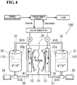
- an RF battery 100 includes a battery cell 10 which is separated into a positive electrode cell 12 and a negative electrode cell 13 by a separator 11 that allows hydrogen ions to permeate.
- the positive electrode cell 12 contains a positive electrode 14 and is connected to a positive electrode electrolyte tank 20 that stores a positive electrode electrolyte via a circulation passage including a supply flow path 30 and a discharge flow path 32.
- the negative electrode cell 13 contains a negative electrode 15 and is connected to a negative electrode electrolyte tank 21 that stores a negative electrode electrolyte via a circulation passage including a supply flow path 31 and a discharge flow path 33.
- the electrolytes in the positive electrode electrolyte tank 20 and the negative electrode electrolyte tank 21 are supplied from the supply flow paths 30 and 31 to the cells 12 and 13 by pumps 34 and 35 provided in the middle of the supply flow paths 30 and 31, discharged from the cells 12 and 13 through the discharge flow paths 32 and 33 to the positive electrode electrolyte tank 20 and the negative electrode electrolyte tank 21, and thus circulated within the cells 12 and 13, respectively. While circulating the electrolytes in such a manner, charging and discharging are performed using the difference in oxidation-reduction potential between ions contained in the positive electrode electrolyte and ions contained in the negative electrode electrolyte. In Fig. 4 , vanadium ions are shown as ions contained in the electrode electrolytes. Solid line arrows indicate charging and dashed line arrows indicate discharging.
- the positive electrode electrolyte tank 20 and the negative electrode electrolyte tank 21 are hermetically sealed such that entry of the air is blocked.
- the pressure of a gas phase portion 20g or 21g in the positive electrode electrolyte tank 20 or negative electrode electrolyte tank 21 becomes negative (less than the atmospheric pressure) when the temperature of the gas phase portion 20g or 21g decreases or the liquid surface of the electrolyte falls at the start of circulation to increase the volume of the gas phase portion 20g or 21g.
- the pressure of the gas phase portion 20g or 21g in the positive electrode electrolyte tank 20 or negative electrode electrolyte tank 21 becomes positive (greater than the atmospheric pressure) when the temperature of the electrolyte increases or the volume of the gas phase portion 20g or 21g decreases.
- the positive electrode electrolyte tank 20 or negative electrode electrolyte tank 21 excessively deforms (expands/contracts) as a result of the positive pressure/negative pressure, there is a concern that the positive electrode electrolyte tank 20 or negative electrode electrolyte tank 21 may be damaged. In particular, when deformation (expansion/contraction) occurs repeatedly, the positive electrode electrolyte tank 20 or negative electrode electrolyte tank 21 is likely to be damaged.
- a breathing bag (pressure adjustment bag) 110 is provided in each of the gas phase portions 20g and 21g of the positive electrode electrolyte tank 20 and the negative electrode electrolyte tank 21, the breathing bag (pressure adjustment bag) 110 being suspended from the top wall of each of the positive electrode electrolyte tank 20 and the negative electrode electrolyte tank 21 (refer to PTL 1).
- the inside of the breathing bag 110 communicates with the atmosphere.
- the breathing bag 110 takes in the atmosphere and expands to reduce the volume of the gas phase portion 20g or 21g, thereby increasing the pressure of the gas phase portion 20g or 21g.
- the breathing bag 110 discharges the internal gas to the atmosphere and contracts to increase the volume of the gas phase portion 20g or 21g, thereby decreasing the pressure of the gas phase portion 20g or 21g.
- the breathing bag 110 discharges the internal gas to the atmosphere and contracts to increase the volume of the gas phase portion 20g or 21g, thereby decreasing the pressure of the gas phase portion 20g or 21g.
- the pressure adjustment bag Since the pressure adjustment bag is provided inside the tank as described above, maintenance of the pressure adjustment bag becomes very complicated.
- the tank is opened in order to visually check whether or not the pressure adjustment bag is operating normally or replace the pressure adjustment bag. In order to open the tank, it is necessary to discharge the RF battery so as to prevent oxidation of the electrolyte.
- the adjustable range of pressure of the gas phase portion is narrow.
- the volume of the pressure adjustment bag is restricted by the volume of the gas phase portion in the tank.
- the present invention has been accomplished under these circumstances, and an object of the present invention is to provide an electrolytic solution circulation type battery including a pressure adjustment mechanism having excellent maintainability.
- Another object of the present invention is to provide an electrolytic solution circulation type battery in which the pressure adjustable range inside the tank is wide.
- An electrolytic solution circulation type battery includes a tank which stores an electrolyte to be circulated to a battery cell.
- the electrolytic solution circulation type battery includes a pressure adjustment mechanism configured to adjust the pressure of a gas phase portion in the tank.
- the pressure adjustment mechanism includes a pressure adjustment bag which is provided outside the tank and expands or contracts in response to changes in pressure of the gas phase portion in the tank.
- the pressure adjustment bag has excellent maintainability. Furthermore, the volume of the pressure adjustment bag to be provided is not greatly restricted.
- the volume of the pressure adjustment bag by setting the volume of the pressure adjustment bag to be 1/30 or more of the volume of the gas phase portion, pressure adjustment can be performed effectively.
- the volume of the pressure adjustment bag By setting the volume of the pressure adjustment bag to be 1/2 or less of the volume of the gas phase portion, the installation space of the pressure adjustment bag does not become excessively large.
- An RF battery according to Embodiment 1 includes, as in the existing RF battery 100 described with reference to Fig. 4 , a battery cell 10, a tank 20 which stores a positive electrode electrolyte to be circulated to a positive electrode cell 12, and a tank 21 which stores a negative electrode electrolyte to be circulated to a negative electrode cell 13.
- the electrode electrolytes are circulated through circulation passages (supply flow paths 30 and 31 and discharge flow paths 32 and 33) by pumps 34 and 35 provided in the middle of the corresponding circulation passages.
- the RF battery according to Embodiment 1 is mainly characterized in that a pressure adjustment mechanism configured to adjust the pressure of a gas phase portion in the tank includes a pressure adjustment bag which is provided outside the tank.
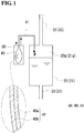
- a pressure adjustment mechanism 4A is configured to adjust the pressure of a gas phase portion 20g or 21g of a positive electrode electrolyte tank 20 or negative electrode electrolyte tank 21.
- the pressure adjustment mechanism 4A includes a pressure adjustment bag 40 which expands or contracts in response to changes in pressure (positive pressure and negative pressure) of the gas phase portion 20g or 21g of the positive electrode electrolyte tank 20 or negative electrode electrolyte tank 21.
- the pressure adjustment bag 40 is provided outside the positive electrode electrolyte tank 20 or negative electrode electrolyte tank 21 and is connected, through a direct duct 41 which communicates with the gas phase portion 20g or 21g, to the positive electrode electrolyte tank 20 or negative electrode electrolyte tank 21.
- each of the positive electrode electrolyte tank 20 and the negative electrode electrolyte tank 21 is provided with the pressure adjustment bag 40.
- only one of the positive electrode electrolyte tank 20 and the negative electrode electrolyte tank 21 may be provided with the pressure adjustment bag 40.
- the pressure adjustment bag 40 adjusts the pressure of the gas phase portion 20g or 21g by expansion or contraction, thereby suppressing excessive deformation (expansion and contraction) of the positive electrode electrolyte tank 20 or negative electrode electrolyte tank 21 and suppressing explosion and compression of the positive electrode electrolyte tank 20 or negative electrode electrolyte tank 21.
- the pressure adjustment bag 40 has both a function of suppressing positive pressure and a function of suppressing negative pressure of the gas phase portion 20g or 21g.
- the pressure adjustment bag 40 In the case where positive pressure is suppressed by the pressure adjustment bag 40, for example, the pressure adjustment bag 40 is maintained in a contracted state.
- the pressure of the gas phase portion 20g or 21g becomes positive (e.g., 0.1 to 10 kPa greater than the atmospheric pressure), as indicated by thick broken-line arrows in Fig. 1 , the pressure adjustment bag 40 takes in gas of the gas phase portion 20g or 21g and expands.
- the gas is an inert gas which will be described later.
- the pressure of the gas phase portion 20g or 21g is decreased to approximately the atmospheric pressure.
- the pressure of the gas phase portion 20g or 21g may become positive, for example, under the influence of the outside air temperature or because of an increase in the temperature of the gas phase portion 20g or 21g, or a decrease in the volume of the gas phase portion 20g or 21g due to a rise of the liquid surface of the electrolyte.
- an inert gas is stored in the pressure adjustment bag 40.
- the pressure adjustment bag 40 contracts and supplies the inert gas inside the pressure adjustment bag 40 to the gas phase portion 20g or 21g.
- the pressure of the gas phase portion 20g or 21g is increased to approximately the atmospheric pressure.
- the pressure of the gas phase portion 20g or 21g may become negative, for example, because of a decrease in the temperature of the gas phase portion 20g or 21g or an increase in the volume of the gas phase portion 20g or 21g due to a fall of the liquid surface of the electrolyte at the start of circulation.
- the inert gas examples include noble gases, such as argon and neon, and nitrogen.
- nitrogen is preferable from the viewpoint of easy availability and inexpensiveness.
- the pressure adjustment bag 40 is installed outside the positive electrode electrolyte tank 20 or negative electrode electrolyte tank 21.
- the pressure adjustment bag 40 By providing the pressure adjustment bag 40 outside the positive electrode electrolyte tank 20 or negative electrode electrolyte tank 21, maintainability of the pressure adjustment bag 40 can be enhanced compared with the case where the pressure adjustment bag 40 is provided inside the positive electrode electrolyte tank 20 or negative electrode electrolyte tank 21.
- the pressure adjustment bag 40 By providing the pressure adjustment bag 40 outside the positive electrode electrolyte tank 20 or negative electrode electrolyte tank 21, it is possible to visually check whether or not the pressure adjustment bag 40 is operating normally or replace the pressure adjustment bag 40 without opening the positive electrode electrolyte tank 20 or negative electrode electrolyte tank 21.
- the volume of the pressure adjustment bag 40 to be provided is not greatly restricted. The reason for this is the volume of the pressure adjustment bag 40 is not restricted by the volume of the gas phase portion 20g or 21g compared with the case where the pressure adjustment bag 40 is installed inside the positive electrode electrolyte tank 20 or negative electrode electrolyte tank 21.
- the size of the positive electrode electrolyte tank 20 or negative electrode electrolyte tank 21 and the volume of the pressure adjustment bag 40 are the same as those in the case where the pressure adjustment bag 40 is provided inside the positive electrode electrolyte tank 20 or negative electrode electrolyte tank 21, it is possible to increase the amount of the electrolyte. Assuming that the amount of the electrolyte in the positive electrode electrolyte tank 20 or negative electrode electrolyte tank 21 and the volume of the pressure adjustment bag 40 are the same as those in the case where the pressure adjustment bag 40 is provided inside the positive electrode electrolyte tank 20 or negative electrode electrolyte tank 21, the size of the positive electrode electrolyte tank 20 or negative electrode electrolyte tank 21 can be decreased.
- the pressure adjustment bag 40 may be made of a single-layer sheet material, but is preferably made of a layered material in which a plurality of layers are stacked.
- the layered material may include a corrosion protection layer 40a and an oxygen barrier layer 40b disposed on an outer periphery thereof.
- the corrosion protection layer 40a prevents damage, such as holes, due to degradation by a mist containing components of the electrolyte (e.g., sulfuric acid) or the like.
- a mist containing components of the electrolyte e.g., sulfuric acid
- the reason for this is that since the inside of the pressure adjustment bag 40 is directly connected to the gas phase portion 20 or 21g of the positive electrode electrolyte tank 20 or negative electrode electrolyte tank 21, there is a possibility that a mist containing components of the electrolyte (e.g., sulfuric acid) will be mixed into the pressure adjustment bag 40.
- a resin that does not react with the electrolyte and has high electrolyte resistance may be used.
- the resin include polyvinyl chloride (PVC), polypropylene (PP), polyethylene (PE), and polytetrafluoroethylene (PTFE).
- PE can be suitably used.
- a PE resin has a high oxygen transmission rate and easily allows oxygen to penetrate the inside thereof.
- the oxygen barrier layer 40b which will be described later, is provided, it is possible to use a PE resin as a constituent material of the corrosion protection layer 40a.
- the PE resin include low-density polyethylene (LDPE) and linear polyethylene (L-LDPE).
- the thickness of the corrosion protection layer 40a can be, for example, 100 to 300 ⁇ m. When the thickness of the corrosion protection layer 40a is 100 ⁇ m or more, pressure resistance can be increased, and when the thickness of the corrosion protection layer 40a is 300 ⁇ m or less, although depending on the material, flexibility and transparency can be easily increased.
- the oxygen barrier layer 40b prevents entry of oxygen from the outside into the pressure adjustment bag 40.
- the oxygen barrier layer 40b covers the entire outer periphery of the corrosion protection layer 40a.
- the oxygen barrier layer 40b As a material for the oxygen barrier layer 40b, a material having a lower oxygen transmission rate than the corrosion protection layer 40a may be used. By forming the oxygen barrier layer 40b using a material having a low oxygen transmission rate, it is possible to prevent entry of oxygen into the corrosion protection layer 40a.
- the oxygen transmission rate is preferably 300 (cc ⁇ 20 ⁇ m/m 2 ⁇ day ⁇ atm) or less, and more preferably 1 (cc ⁇ 20 ⁇ m/m 2 ⁇ day ⁇ atm) or less, in particular, 0.1 (cc ⁇ 20 ⁇ m/m 2 ⁇ day ⁇ atm) or less.
- any kind of material can be used as long as it has a low oxygen transmission rate, and the material may be at least one selected from a metallic material, an inorganic material, and an organic material.
- the metallic material include aluminum and alloys thereof, iron and alloys thereof, copper and alloys thereof, and magnesium and alloys thereof.
- the inorganic material include carbon.
- the organic material include ethylene-vinyl alcohol copolymers (saponified ethylene-vinyl acetate random copolymers), polyvinylidene chloride resins, polyvinyl alcohol resins, and nylon 6.
- an ethylene-vinyl alcohol copolymer is preferable as a material for the oxygen barrier layer 40b.
- the thickness of the oxygen barrier layer 40b is preferably, for example, 20 to 300 ⁇ m. When the thickness of the oxygen barrier layer 40b is 20 ⁇ m or more, entry of oxygen can be satisfactorily prevented. When the thickness of the oxygen barrier layer 40b is 300 ⁇ m or less, the thickness is not increased excessively.
- the pressure adjustment bag 40 may include a plurality of corrosion protection layers 40a or a plurality of oxygen barrier layers 40b.
- a single or multilayered protective layer may be disposed on an outer periphery of the oxygen barrier layer 40b.
- the material for the protective layer may be the same resin as that of the corrosion protection layer 40a, such as LDPE, or other resin, such as polyamide (PA), cross-linked PE, high-density PE, or epoxy.
- the volume of the pressure adjustment bag 40 is preferably 1/30 to 1/2 of the volume of the gas phase portion 20g or 21g. By setting the volume of the pressure adjustment bag 40 to be 1/30 or more of the volume of the gas phase portion 20g or 21g, pressure adjustment of the gas phase portion 20g or 21g can be performed satisfactorily. By setting the volume of the pressure adjustment bag 40 to be 1/2 or less of the volume of the gas phase portion 20g or 21g, the installation space of the pressure adjustment bag 40 does not become excessively large. In particular, the volume of the pressure adjustment bag 40 is preferably 1/10 to 1/5 of the volume of the gas phase portion 20g or 21g. The volume of the pressure adjustment bag 40 refers to the maximum volume to which the pressure adjustment bag 40 can be expanded.
- a single or a plurality of pressure adjustment bags 40 may be provided for each of the gas phase portions 20g and 21g.
- the size of each pressure adjustment bag 40 can be decreased.
- the total volume of the plurality of pressure adjustment bags 40 is preferably 1/30 to 1/2 of the gas phase portion 20g or 21g.
- the direct duct 41 allows the pressure adjustment bag 40 and the gas phase portion 20g or 21g to communicate with each other.
- One end of the direct duct 41 is open to the pressure adjustment bag 40 and the other end of the direct duct 41 is open to the gas phase portion 20g or 21g.
- the direct duct 41 has a size that allows the pressure adjustment bag 40 to rapidly expand or contract when the pressure of the gas phase portion 20g or 21g changes.
- the size of the direct duct 41 depends on the balance between the length and the inside diameter, a smaller length and a larger inside diameter are preferable.
- the length of the direct duct 41 can be set to be about 100 to 10,000 mm, and the inside diameter of the direct duct 41 can be set to be about 5 to 100 mm.
- a material for the direct duct 41 a material having excellent corrosion resistance is suitable, as in the corrosion protection layer 40a of the pressure adjustment bag 40.
- a box 60 which contains the pressure adjustment bag 40 is disposed on the outer periphery of the pressure adjustment bag 40.
- the box 60 can mechanically protect the pressure adjustment bag 40.
- the box 60 bears the internal pressure of the pressure adjustment bag 40 due to expansion. In that case, explosion of the pressure adjustment bag 40 can be effectively prevented.
- a material having low pressure resistance can be used as a material for the pressure adjustment bag 40. Accordingly, it is possible to increase the freedom of selection of the material for the pressure adjustment bag 40.
- the size of the box 60 is smaller than the volume of the pressure adjustment bag 40.
- the size of the box 60 is 98% or less of the volume of the pressure adjustment bag 40.
- the size of the box 60 is about 80% or more of the volume of the pressure adjustment bag 40.
- the box 60 is shown larger than the pressure adjustment bag 40.
- the box 60 has the functions of mechanical protection and bearing the pressure described above, and furthermore preferably is formed such that the pressure adjustment bag 40 placed therein can be viewed through part of the box 60.
- at least part of the box 60 may be formed of a transparent member, or part of the box 60 may be formed of a grid-like member. In that case, the pressure adjustment bag 40 can be easily visually checked without opening the box 60.
- a material for the box 60 As a material for the box 60, a material having a strength that can withstand the pressure borne by the box 60 may be used. In addition, when the box 60 is installed outdoors, a material having excellent corrosion resistance and weather resistance is preferable. Examples of the material include stainless steel, PVC, and PE (in particular, resin compositions of PVC and PE with enhanced weather resistance).
- the pressure adjustment bag 40 has excellent maintainability. Furthermore, by providing the pressure adjustment bag 40 outside the positive electrode electrolyte tank 20 or negative electrode electrolyte tank 21, the volume of the pressure adjustment bag 40 is not greatly restricted, and it is possible to widen the adjustable range of pressure of the gas phase portion 20g or 21g by the pressure adjustment bag 40.
- the size of the positive electrode electrolyte tank 20 or negative electrode electrolyte tank 21 and the volume of the pressure adjustment bag 40 are the same as those in the case where the pressure adjustment bag 40 is provided inside the positive electrode electrolyte tank 20 or negative electrode electrolyte tank 21, it is possible to increase the amount of the electrolyte. Consequently, the battery capacity can be increased.
- the size of the positive electrode electrolyte tank 20 or negative electrode electrolyte tank 21 can be decreased. Consequently, the space for installing the positive electrode electrolyte tank 20 or negative electrode electrolyte tank 21 can be decreased, and the remaining space can be effectively used.
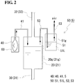
- a pressure adjustment mechanism 4B includes a pressure adjustment bag 40 and also includes a gas discharge mechanism 5 configured to discharge gas of the gas phase portion 20g or 21g in the positive electrode electrolyte tank 20 or negative electrode electrolyte tank 21 to the outside of the positive electrode electrolyte tank 20 or negative electrode electrolyte tank 21. That is, an RF battery according to Embodiment 2 differs from the RF battery according to Embodiment 1 in that a gas discharge mechanism 5 is provided, but otherwise Embodiment 2 has the same configuration as that of Embodiment 1.
- the pressure adjustment bag 40 is used to suppress the negative pressure of the gas phase portion 20g or 21g
- the gas discharge mechanism 5 is used to suppress the positive pressure of the gas phase portion 20g or 21g.
- the difference from Embodiment 1 will be mainly described below.
- the same components as those of Embodiment 1 are denoted by the same reference signs, and description thereof is omitted.
- the thick solid-line arrows indicate the flow of gas.
- the gas discharge mechanism 5 is configured to discharge gas of the gas phase portion 20g or 21g to the outside of the positive electrode electrolyte tank 20 or negative electrode electrolyte tank 21, thus adjusting the pressure of the gas phase portion 20g or 21g. In such a manner, explosion of the positive electrode electrolyte tank 20 or negative electrode electrolyte tank 21 due to excessive expansion is prevented.
- the gas discharge mechanism 5 includes a water seal valve 50.
- the water seal valve 50 includes a container 51, a pressure regulating liquid 51L stored therein, a connecting pipe 52 which communicates with the gas phase portion 20g or 21g, and a discharge pipe 53 which discharges the gas inside the container 51 to the outside of the container 51.
- the connecting pipe 52 has one end open to the gas phase portion 20g or 21g in the positive electrode electrolyte tank 20 or negative electrode electrolyte tank 21, extends through a gas phase portion in the container 51, and has the other end open in the pressure regulating liquid 51L.
- the discharge pipe 53 has one end open to the gas phase portion 51g in the container 51 and the other end open to the atmosphere.
- the operation of discharging gas of the gas phase portion 20g or 21g by the water seal valve 50 is performed as follows.
- the pressure of the gas phase portion 20g or 21g in the positive electrode electrolyte tank 20 or negative electrode electrolyte tank 21 becomes positive (e.g., 0.1 to 10 kPa greater than the atmospheric pressure)
- the gas of the gas phase portion 20g or 21g passes through the connecting pipe 52 and is discharged into the pressure regulating liquid 51L in the container 51.
- the gas discharged into the pressure regulating liquid 51L in the form of bubbles, rises in the liquid and moves into the gas phase portion 51g in the container 51.
- the gas of the gas phase portion 51g in the container 51 is discharged through the discharge pipe 53 to the atmosphere as indicated by the thick solid-line arrow of Fig. 2 .
- the positive pressure of the gas phase portion 20g or 21g is suppressed, and the pressure of the gas phase portion 20g or 21g is adjusted to approximately the atmospheric pressure.
- explosion of the positive electrode electrolyte tank 20 or negative electrode electrolyte tank 21 due to excessive expansion can be prevented.
- a resin such as polyvinyl chloride (PVC) may be used.
- PVC polyvinyl chloride
- Polyvinyl chloride is preferable because it has excellent water resistance, acid resistance, alkali resistance, and solvent resistance and is inexpensive.
- As the pressure regulating liquid 51L water which is inexpensive and easily available or an aqueous solution can be used.
- aqueous solution for example, a dilute sulfuric acid solution or the like may be used. The dilute sulfuric acid solution is unlikely to freeze even in a low-temperature environment, and therefore is preferable.
- the water seal valve 50 also has a function of preventing backflow of the gas into the positive electrode electrolyte tank 20 or negative electrode electrolyte tank 21.
- the reason for this is that since the end of the connecting pipe 52, which is connected to the gas phase portion 20g or 21g in the positive electrode electrolyte tank 20 or negative electrode electrolyte tank 21, is open in the pressure regulating liquid 51L, the gas of the gas phase portion 51g in the container 51, which communicates through the discharge pipe 53 with the atmosphere, does not flow into the connecting pipe 52.
- gas removal equipment (not shown) is provided in the middle of the discharge pipe 53.
- gas may be generated in the circulation passage of the electrolyte (hereinafter, the gas generated in the electrolyte will be referred to as generated gas).
- the gas generated in the electrolyte will be referred to as generated gas.
- the generated gas is discharged through the discharge pipe 53 to the outside of the positive electrode electrolyte tank 20 or negative electrode electrolyte tank 21 (into the atmosphere).
- the gas removal equipment for example, a filter described in Japanese Unexamined Patent Application Publication No. 2007-311209 or the like may be used.
- the gas discharge mechanism 5 may have a structure other than the water seal valve 50.
- the gas discharge mechanism 5 may include, for example, a pressure gauge provided in the gas phase portion 20g or 21g, a discharge pipe 53 whose one end is open to the gas phase portion 20g or 21g and whose other end is open to the atmosphere, and a valve disposed therebetween.
- the pressure of the gas phase portion 20g or 21g is measured by the pressure gauge, and by opening the valve on the basis of the measurement result, the gas of the gas phase portion 20g or 21g can be discharged to the outside of the positive electrode electrolyte tank 20 or negative electrode electrolyte tank 21.
- the negative pressure of the gas phase portion 20g or 21g can be suppressed by the pressure adjustment bag 40, and the positive pressure of the gas phase portion 20g or 21g can be suppressed by the gas discharge mechanism 5.
- positive pressure suppression and negative pressure suppression of the gas phase portion 20g or 21g can be performed by different members, positive pressure suppression and negative pressure suppression can be performed effectively.
- the volume of the pressure adjustment bag 40 is the same as that in the case where the pressure adjustment bag 40 is used to suppress both the positive pressure and the negative pressure, it is possible to widen the range in which the negative pressure can be suppressed.
- an RF battery is provided with a pressure adjustment mechanism 4C including a pressure adjustment bag 40 and a gas discharge mechanism 5 and may also be provided with a gas supply mechanism 7. That is, the RF battery according to Embodiment 3 differs from the RF battery according to Embodiment 2 in that a gas supply mechanism 7 is provided, but otherwise Embodiment 3 has the same configuration as that of Embodiment 2. The difference from Embodiment 2 will be mainly described below. The same components as those of Embodiment 2 are denoted by the same reference signs, and a description thereof is omitted. In Fig. 3 , the thick solid-line arrows and the thick broken-line arrows indicate the flow of gas.
- the gas supply mechanism 7 is configured to supply a flow gas including the same inert gas as that described above to the gas phase portion 20g or 21g. Thereby, generated gas filling the gas phase portion 20g or 21g is diluted. The diluted generated gas can be discharged by the gas discharge mechanism 5 to the outside of the positive electrode electrolyte tank 20 or negative electrode electrolyte tank 21.
- the gas supply mechanism 7 includes a gas supply source 70 and a gas supply duct 71.
- the gas supply source 70 stores or generates a flow gas including an inert gas to be supplied to the positive electrode electrolyte tank 20 or negative electrode electrolyte tank 21.
- the gas supply source 70 may have, for example, a structure including a storing member (cylinder, tank, or the like) for storing an inert gas, or a structure including a gas generator that generates an inert gas.
- the former structure can be easily fabricated, which is preferable. In the latter structure, it is possible to reduce time and effort for replenishing the inert gas.
- a gas generator that generates nitrogen since nitrogen can be extracted from the atmosphere, it is possible to semi-permanently supply a flow gas.
- the percentage of the inert gas in the flow gas is preferably 99.9% by volume or more. As the percentage is increased, deterioration of the electrolyte due to the flow gas can be suppressed more securely. When the percentage is 99.9% by volume or more, theoretically, it is believed that deterioration of the electrolyte can be suppressed to such an extent that no real operational damage is caused for 10 to 20 years.
- a flow gas is supplied from the gas supply source 70 through the gas supply duct 71 to the gas phase portion 20g or 21g in the positive electrode electrolyte tank 20 or negative electrode electrolyte tank 21 (thick solid-line arrow).
- One end of the gas supply duct 71 is connected to the gas supply source 70, and the other end of the gas supply duct 71 is open to the gas phase portion 20g or 21g of the positive electrode electrolyte tank 20 or negative electrode electrolyte tank 21.
- the gas supply duct 71 is provided with a gas flow control mechanism configured to constantly supply a flow gas to the gas phase portion 20g or 21g.
- the gas flow control mechanism controls the feed rate of a flow gas to be supplied from the gas supply source 70 to the gas phase portion 20g or 21g in the positive electrode electrolyte tank 20 or negative electrode electrolyte tank 21 to a certain rate equal to or more than a predetermined value.
- the gas flow control mechanism includes a flow meter 72 and a valve 73.
- the flow meter 72 measures the flow rate of the flow gas flowing through the gas supply duct 71.
- the valve 73 controls the flow rate of the flow gas flowing through the gas supply duct 71 by adjusting the valve travel on the basis of the flow rate measured by the flow meter 72 so that the flow rate is a certain value equal to or more than a predetermined value.
- Determination of the valve travel on the basis of the flow rate and operation of the valve 73 can be performed by a control unit such as a computer (not shown).
- a control unit such as a computer (not shown).
- the feed rate of the flow gas to the gas phase portion 20g or 21g in the positive electrode electrolyte tank 20 or negative electrode electrolyte tank 21 is constant, for example, at 0.1 liter/min or more.
- the generated gas of the gas phase portion 20g or 21g can be diluted sufficiently, and by discharging the diluted generated gas by the gas discharge mechanism 5, the gas phase portion 20g or 21g can be ventilated sufficiently.
- the pressure adjustment mechanism 4C includes a pressure adjustment bag 40 and a gas discharge mechanism 5 (water seal valve 50) as in Embodiment 2.
- the pressure adjustment bag 40 communicates with the gas phase portion 20g or 21g through the gas supply duct 71.
- a communicating duct 42 whose one end is connected to the pressure adjustment bag 40 and whose other end is made to communicate with the middle of the gas supply duct 71 is provided.
- the pressure adjustment bag 40 contracts and allows the inert gas inside the pressure adjustment bag 40 to flow through communicating duct 42 to be discharged into the gas supply duct 71 as indicated by the thick solid-line arrow in Fig. 3 .
- the inert gas flows together with the inert gas fed from the gas supply source 70 and is supplied to the gas phase portion 20g or 21g.
- the pressure of the gas phase portion 20g or 21g is increased to approximately the atmospheric pressure.
- part of the inert gas fed from the gas supply source 70 is introduced through the communicating duct 42 into the pressure adjustment bag 40 and stored as indicated by the thick broken-line arrow in Fig. 3 .
- the gas discharge mechanism 5 discharges the generated gas which has been diluted by the gas supply mechanism 7.
- the pressure of the gas phase portion 20g or 21g is made positive by the supply of the flow gas, as described above, the generated gas passes through the connecting pipe 52, the pressure regulating liquid 51L, the gas phase portion 51g in the container 51, and the discharge pipe 53 in that order and is discharged into the atmosphere. Since the generate gas can be diluted by the gas supply mechanism 7, the generated gas can be discharged at a low concentration into the atmosphere.
- the generated gas in addition to negative pressure suppression by the pressure adjustment bag 40, by providing the gas supply mechanism 7, the generated gas can be diluted, and by providing the gas discharge mechanism 5, the generated gas can be discharged at a low concentration into the atmosphere. Therefore, the inside of the positive electrode electrolyte tank 20 or negative electrode electrolyte tank 21 can be ventilated, and it is possible to prevent stagnation of generated harmful gas in the tank. In particular, by constantly supplying the flow gas, the generated gas in the gas phase portion 20g or 21g can be always maintained at a low concentration.
- a gas phase communicating pipe which connects the gas phase portions of the tanks to each other may be provided.
- the two tanks can be considered to have one gas phase portion. Therefore, a pressure adjustment bag may be provided only on the gas phase portion of one of the tanks.
- the gas discharge mechanism and the gas supply mechanism each may be provided only on the gas phase portion of one of the tanks.
- the pressure adjustment bag and the gas discharge mechanism may be provided on the negative electrode electrolyte tank, and the gas supply mechanism may be provided on the positive electrode electrolyte tank.
- the feed rate of the flow gas may be controlled, for example, such that the feed rate of the flow gas into the gas phase portion in the negative electrode electrolyte tank is 0.1 liter/min or more. Thereby, the gas phase portion in each tank can be ventilated sufficiently.
- the pressure adjustment bag may be directly connected to the gas phase portion through a direct duct instead of being connected through the gas supply duct to the gas phase portion.
- Electrolytic solution circulation type batteries according to an embodiment of the present invention can be suitably used, with respect to new energy power generation, such as photovoltaic power generation and wind power generation, for the purpose of stabilizing fluctuation of power output, storing generated power during oversupply, leveling load, and the like. Furthermore, electrolytic solution circulation type batteries according to an embodiment of the present invention can be provided in a general power plant and suitably used as large-capacity storage batteries as countermeasures against voltage sag/power failure and for the purpose of leveling load.
Landscapes
- Life Sciences & Earth Sciences (AREA)
- Engineering & Computer Science (AREA)
- Manufacturing & Machinery (AREA)
- Sustainable Development (AREA)
- Sustainable Energy (AREA)
- Chemical & Material Sciences (AREA)
- Chemical Kinetics & Catalysis (AREA)
- Electrochemistry (AREA)
- General Chemical & Material Sciences (AREA)
- Fuel Cell (AREA)
Claims (7)
- Batterie mit Elektrolytlösungsumwälzung, mit:einem Behälter, der einen zu einer Batteriezelle umzuwälzenden Elektrolyt enthält; undeinem Druckeinstellmechanismus, der ausgebildet ist, den Druck eines Gasphasenbereichs in dem Behälter einzustellen,wobei der Druckeinstellmechanismus einen Druckeinstellbeutel aufweist, der außerhalb des Behälters vorgesehen ist und sich in Reaktion auf Änderungen des Drucks des Gasphasenbereichs in dem Behälter ausdehnt oder zusammenzieht.
- Batterie mit Elektrolytlösungsumwälzung nach Anspruch 1, wobei der Druckeinstellmechanismus einen Gasableitmechanismus aufweist, der ausgebildet ist, Gas des Gasphasenbereichs in dem Behälter nach außen abzuleiten.
- Batterie mit Elektrolytlösungsumwälzung nach Anspruch 1 oder 2, die ferner einen Gaszuführmechanismus aufweist, der ausgebildet ist, ein Strömungsgas, das ein inertes Gas enthält, über eine Gaszufuhrleitung dem Gasphasenbereich zuzuführen.
- Batterie mit Elektrolytlösungsumwälzung nach Anspruch 3, wobei der Druckeinstellbeutel mit dem Gasphasenbereich über die Gaszufuhrleitung in Verbindung steht.
- Batterie mit Elektrolytlösungsumwälzung nach einem der Ansprüche 1 bis 4, die ferner eine Box aufweist, die den Druckeinstellbeutel enthält und den Innendurch des Druckeinstellbeutels durch Ausdehnung aufnimmt.
- Batterie mit Elektrolytlösungsumwälzung nach einem der Ansprüche 1 bis 5, wobei der Druckeinstellbeutel aus einem Schichtmaterial mit einer Korrosionsschutzschicht und einer Sauerstoffbarrierenschicht, die am äußeren Rand vorgesehen ist, hergestellt ist.
- Batterie mit Elektrolytlösungsumwälzung nach einem der Ansprüche 1 bis 6, wobei das Volumen des Druckeinstellbeutels 1/30 bis 1/2 des Volumens des Gasphasenbereichs beträgt.
Applications Claiming Priority (2)
| Application Number | Priority Date | Filing Date | Title |
|---|---|---|---|
| JP2014152431A JP6308366B2 (ja) | 2014-07-25 | 2014-07-25 | 電解液循環型電池 |
| PCT/JP2015/069225 WO2016013377A1 (ja) | 2014-07-25 | 2015-07-03 | 電解液循環型電池 |
Publications (3)
| Publication Number | Publication Date |
|---|---|
| EP3174149A1 EP3174149A1 (de) | 2017-05-31 |
| EP3174149A4 EP3174149A4 (de) | 2017-07-12 |
| EP3174149B1 true EP3174149B1 (de) | 2018-08-29 |
Family
ID=55162909
Family Applications (1)
| Application Number | Title | Priority Date | Filing Date |
|---|---|---|---|
| EP15824820.3A Active EP3174149B1 (de) | 2014-07-25 | 2015-07-03 | Batterie mit elektrolytlösungszirkulation |
Country Status (6)
| Country | Link |
|---|---|
| US (1) | US10396372B2 (de) |
| EP (1) | EP3174149B1 (de) |
| JP (1) | JP6308366B2 (de) |
| CN (2) | CN113571741A (de) |
| TW (1) | TWI631759B (de) |
| WO (1) | WO2016013377A1 (de) |
Families Citing this family (9)
| Publication number | Priority date | Publication date | Assignee | Title |
|---|---|---|---|---|
| KR101655292B1 (ko) * | 2016-04-15 | 2016-09-07 | 스탠다드에너지(주) | 레독스 흐름전지 |
| AU2016403177B2 (en) * | 2016-04-21 | 2021-08-05 | Sumitomo Electric Industries, Ltd. | Container-type battery |
| US11791488B2 (en) | 2016-07-26 | 2023-10-17 | Sumitomo Electric Industries, Ltd. | Flow battery system |
| JP6153100B1 (ja) * | 2016-07-26 | 2017-06-28 | 住友電気工業株式会社 | 電解液流通型電池用電解液、及び電解液流通型電池システム |
| TWI626062B (zh) * | 2017-03-10 | 2018-06-11 | 新利虹科技股份有限公司 | 呼吸裝置操作方法 |
| EP3734733A1 (de) * | 2017-12-27 | 2020-11-04 | Showa Denko K.K. | Redox-flow-batterie |
| CN113036196A (zh) * | 2019-12-09 | 2021-06-25 | 中国科学院大连化学物理研究所 | 一种降低液流电池电解液迁移的通用装置 |
| WO2024036039A1 (en) * | 2022-08-09 | 2024-02-15 | Ess Tech, Inc. | Negative electrolyte management system |
| EP4548770A1 (de) | 2023-11-03 | 2025-05-07 | Olimp Laboratories spolka z ograniczona Odpowiedzialnoscia | Partikel mit milchsäurebakterien, verfahren zu ihrer herstellung und ihre verwendung |
Family Cites Families (15)
| Publication number | Priority date | Publication date | Assignee | Title |
|---|---|---|---|---|
| US3751225A (en) * | 1970-03-02 | 1973-08-07 | Pollution Control Ind Inc | Sterilizing with liquid spray containing ozone |
| JPH01265825A (ja) * | 1988-04-15 | 1989-10-23 | Matsushita Refrig Co Ltd | 生鮮物貯蔵装置 |
| US6244441B1 (en) * | 1999-11-10 | 2001-06-12 | Cryovac, Inc. | Heat sealable barrier film for fluid fillable packaging cushions and cushions made therefrom |
| JP3642732B2 (ja) * | 2000-12-06 | 2005-04-27 | 住友電気工業株式会社 | 圧力変動防止タンク構造、電解液循環型2次電池およびレドックスフロー型2次電池 |
| US7364815B2 (en) * | 2004-03-09 | 2008-04-29 | Matsushita Electric Industrial Co., Ltd. | Method of preserving fuel cell membrane electrode assembly |
| JP5148842B2 (ja) * | 2006-05-18 | 2013-02-20 | 住友電気工業株式会社 | レドックスフロー電池 |
| JP5217147B2 (ja) * | 2006-10-18 | 2013-06-19 | トヨタ自動車株式会社 | 燃料電池システムおよびその膜含水量調節方法 |
| JP2009289535A (ja) * | 2008-05-28 | 2009-12-10 | Toshiba Corp | 燃料電池 |
| JP2010170782A (ja) * | 2009-01-21 | 2010-08-05 | Sharp Corp | レドックスフロー電池およびその充放電方法 |
| EP2290729B1 (de) * | 2009-08-24 | 2012-10-10 | Carl Freudenberg KG | Elektrischer Energiespeicher mit Volumenkompensationseinrichtung |
| CN102148388B (zh) * | 2010-02-10 | 2013-08-28 | 大连融科储能技术发展有限公司 | 一种氧化还原液流电池系统 |
| WO2012053324A1 (ja) * | 2010-10-21 | 2012-04-26 | 日産自動車株式会社 | 燃料電池システムの運転方法 |
| WO2012117543A1 (ja) | 2011-03-02 | 2012-09-07 | 日新電機株式会社 | 電力貯蔵電池 |
| JP2014127263A (ja) * | 2012-12-25 | 2014-07-07 | Mitsubishi Motors Corp | レドックスフロー電池 |
| CN103730677A (zh) * | 2014-01-26 | 2014-04-16 | 湖南省银峰新能源有限公司 | 钒液流电池智能控制系统 |
-
2014
- 2014-07-25 JP JP2014152431A patent/JP6308366B2/ja active Active
-
2015
- 2015-07-03 US US15/327,329 patent/US10396372B2/en active Active
- 2015-07-03 CN CN202110677992.1A patent/CN113571741A/zh active Pending
- 2015-07-03 WO PCT/JP2015/069225 patent/WO2016013377A1/ja not_active Ceased
- 2015-07-03 CN CN201580040252.XA patent/CN106537675A/zh active Pending
- 2015-07-03 EP EP15824820.3A patent/EP3174149B1/de active Active
- 2015-07-09 TW TW104122324A patent/TWI631759B/zh active
Non-Patent Citations (1)
| Title |
|---|
| None * |
Also Published As
| Publication number | Publication date |
|---|---|
| TWI631759B (zh) | 2018-08-01 |
| US20170194660A1 (en) | 2017-07-06 |
| US10396372B2 (en) | 2019-08-27 |
| EP3174149A4 (de) | 2017-07-12 |
| WO2016013377A1 (ja) | 2016-01-28 |
| JP2016031790A (ja) | 2016-03-07 |
| CN113571741A (zh) | 2021-10-29 |
| EP3174149A1 (de) | 2017-05-31 |
| CN106537675A (zh) | 2017-03-22 |
| JP6308366B2 (ja) | 2018-04-11 |
| TW201611401A (zh) | 2016-03-16 |
Similar Documents
| Publication | Publication Date | Title |
|---|---|---|
| EP3174149B1 (de) | Batterie mit elektrolytlösungszirkulation | |
| EP3145016B1 (de) | Redox-flussbatterie | |
| US10665881B2 (en) | Redox flow battery system, pump control unit, and method for operating redox flow battery | |
| TWI631758B (zh) | 氧化還原液流電池系統及氧化還原液流電池之運轉方法 | |
| JP6950870B2 (ja) | レドックスフロー電池 | |
| US10090541B2 (en) | Redox flow battery | |
| JP2015232960A (ja) | 電池システム | |
| WO2015174282A1 (ja) | レドックスフロー電池 | |
| JP7010219B2 (ja) | レドックスフロー電池 | |
| AU2017390079B2 (en) | Redox flow battery | |
| JP6268531B2 (ja) | レドックスフロー電池 |
Legal Events
| Date | Code | Title | Description |
|---|---|---|---|
| STAA | Information on the status of an ep patent application or granted ep patent |
Free format text: STATUS: THE INTERNATIONAL PUBLICATION HAS BEEN MADE |
|
| PUAI | Public reference made under article 153(3) epc to a published international application that has entered the european phase |
Free format text: ORIGINAL CODE: 0009012 |
|
| STAA | Information on the status of an ep patent application or granted ep patent |
Free format text: STATUS: REQUEST FOR EXAMINATION WAS MADE |
|
| 17P | Request for examination filed |
Effective date: 20170120 |
|
| AK | Designated contracting states |
Kind code of ref document: A1 Designated state(s): AL AT BE BG CH CY CZ DE DK EE ES FI FR GB GR HR HU IE IS IT LI LT LU LV MC MK MT NL NO PL PT RO RS SE SI SK SM TR |
|
| AX | Request for extension of the european patent |
Extension state: BA ME |
|
| A4 | Supplementary search report drawn up and despatched |
Effective date: 20170612 |
|
| RIC1 | Information provided on ipc code assigned before grant |
Ipc: H01M 8/18 20060101AFI20170602BHEP Ipc: H01M 8/04 20160101ALI20170602BHEP |
|
| DAV | Request for validation of the european patent (deleted) | ||
| DAX | Request for extension of the european patent (deleted) | ||
| GRAP | Despatch of communication of intention to grant a patent |
Free format text: ORIGINAL CODE: EPIDOSNIGR1 |
|
| STAA | Information on the status of an ep patent application or granted ep patent |
Free format text: STATUS: GRANT OF PATENT IS INTENDED |
|
| INTG | Intention to grant announced |
Effective date: 20180314 |
|
| GRAS | Grant fee paid |
Free format text: ORIGINAL CODE: EPIDOSNIGR3 |
|
| GRAA | (expected) grant |
Free format text: ORIGINAL CODE: 0009210 |
|
| STAA | Information on the status of an ep patent application or granted ep patent |
Free format text: STATUS: THE PATENT HAS BEEN GRANTED |
|
| AK | Designated contracting states |
Kind code of ref document: B1 Designated state(s): AL AT BE BG CH CY CZ DE DK EE ES FI FR GB GR HR HU IE IS IT LI LT LU LV MC MK MT NL NO PL PT RO RS SE SI SK SM TR |
|
| REG | Reference to a national code |
Ref country code: GB Ref legal event code: FG4D |
|
| REG | Reference to a national code |
Ref country code: CH Ref legal event code: EP |
|
| REG | Reference to a national code |
Ref country code: AT Ref legal event code: REF Ref document number: 1036223 Country of ref document: AT Kind code of ref document: T Effective date: 20180915 |
|
| REG | Reference to a national code |
Ref country code: IE Ref legal event code: FG4D |
|
| REG | Reference to a national code |
Ref country code: DE Ref legal event code: R096 Ref document number: 602015015781 Country of ref document: DE |
|
| REG | Reference to a national code |
Ref country code: NL Ref legal event code: MP Effective date: 20180829 |
|
| REG | Reference to a national code |
Ref country code: LT Ref legal event code: MG4D |
|
| PG25 | Lapsed in a contracting state [announced via postgrant information from national office to epo] |
Ref country code: NL Free format text: LAPSE BECAUSE OF FAILURE TO SUBMIT A TRANSLATION OF THE DESCRIPTION OR TO PAY THE FEE WITHIN THE PRESCRIBED TIME-LIMIT Effective date: 20180829 Ref country code: BG Free format text: LAPSE BECAUSE OF FAILURE TO SUBMIT A TRANSLATION OF THE DESCRIPTION OR TO PAY THE FEE WITHIN THE PRESCRIBED TIME-LIMIT Effective date: 20181129 Ref country code: GR Free format text: LAPSE BECAUSE OF FAILURE TO SUBMIT A TRANSLATION OF THE DESCRIPTION OR TO PAY THE FEE WITHIN THE PRESCRIBED TIME-LIMIT Effective date: 20181130 Ref country code: LT Free format text: LAPSE BECAUSE OF FAILURE TO SUBMIT A TRANSLATION OF THE DESCRIPTION OR TO PAY THE FEE WITHIN THE PRESCRIBED TIME-LIMIT Effective date: 20180829 Ref country code: IS Free format text: LAPSE BECAUSE OF FAILURE TO SUBMIT A TRANSLATION OF THE DESCRIPTION OR TO PAY THE FEE WITHIN THE PRESCRIBED TIME-LIMIT Effective date: 20181229 Ref country code: NO Free format text: LAPSE BECAUSE OF FAILURE TO SUBMIT A TRANSLATION OF THE DESCRIPTION OR TO PAY THE FEE WITHIN THE PRESCRIBED TIME-LIMIT Effective date: 20181129 Ref country code: SE Free format text: LAPSE BECAUSE OF FAILURE TO SUBMIT A TRANSLATION OF THE DESCRIPTION OR TO PAY THE FEE WITHIN THE PRESCRIBED TIME-LIMIT Effective date: 20180829 Ref country code: RS Free format text: LAPSE BECAUSE OF FAILURE TO SUBMIT A TRANSLATION OF THE DESCRIPTION OR TO PAY THE FEE WITHIN THE PRESCRIBED TIME-LIMIT Effective date: 20180829 Ref country code: FI Free format text: LAPSE BECAUSE OF FAILURE TO SUBMIT A TRANSLATION OF THE DESCRIPTION OR TO PAY THE FEE WITHIN THE PRESCRIBED TIME-LIMIT Effective date: 20180829 |
|
| REG | Reference to a national code |
Ref country code: AT Ref legal event code: MK05 Ref document number: 1036223 Country of ref document: AT Kind code of ref document: T Effective date: 20180829 |
|
| PG25 | Lapsed in a contracting state [announced via postgrant information from national office to epo] |
Ref country code: AL Free format text: LAPSE BECAUSE OF FAILURE TO SUBMIT A TRANSLATION OF THE DESCRIPTION OR TO PAY THE FEE WITHIN THE PRESCRIBED TIME-LIMIT Effective date: 20180829 Ref country code: LV Free format text: LAPSE BECAUSE OF FAILURE TO SUBMIT A TRANSLATION OF THE DESCRIPTION OR TO PAY THE FEE WITHIN THE PRESCRIBED TIME-LIMIT Effective date: 20180829 Ref country code: HR Free format text: LAPSE BECAUSE OF FAILURE TO SUBMIT A TRANSLATION OF THE DESCRIPTION OR TO PAY THE FEE WITHIN THE PRESCRIBED TIME-LIMIT Effective date: 20180829 |
|
| PG25 | Lapsed in a contracting state [announced via postgrant information from national office to epo] |
Ref country code: EE Free format text: LAPSE BECAUSE OF FAILURE TO SUBMIT A TRANSLATION OF THE DESCRIPTION OR TO PAY THE FEE WITHIN THE PRESCRIBED TIME-LIMIT Effective date: 20180829 Ref country code: PL Free format text: LAPSE BECAUSE OF FAILURE TO SUBMIT A TRANSLATION OF THE DESCRIPTION OR TO PAY THE FEE WITHIN THE PRESCRIBED TIME-LIMIT Effective date: 20180829 Ref country code: AT Free format text: LAPSE BECAUSE OF FAILURE TO SUBMIT A TRANSLATION OF THE DESCRIPTION OR TO PAY THE FEE WITHIN THE PRESCRIBED TIME-LIMIT Effective date: 20180829 Ref country code: CZ Free format text: LAPSE BECAUSE OF FAILURE TO SUBMIT A TRANSLATION OF THE DESCRIPTION OR TO PAY THE FEE WITHIN THE PRESCRIBED TIME-LIMIT Effective date: 20180829 Ref country code: RO Free format text: LAPSE BECAUSE OF FAILURE TO SUBMIT A TRANSLATION OF THE DESCRIPTION OR TO PAY THE FEE WITHIN THE PRESCRIBED TIME-LIMIT Effective date: 20180829 Ref country code: ES Free format text: LAPSE BECAUSE OF FAILURE TO SUBMIT A TRANSLATION OF THE DESCRIPTION OR TO PAY THE FEE WITHIN THE PRESCRIBED TIME-LIMIT Effective date: 20180829 |
|
| PG25 | Lapsed in a contracting state [announced via postgrant information from national office to epo] |
Ref country code: SK Free format text: LAPSE BECAUSE OF FAILURE TO SUBMIT A TRANSLATION OF THE DESCRIPTION OR TO PAY THE FEE WITHIN THE PRESCRIBED TIME-LIMIT Effective date: 20180829 Ref country code: SM Free format text: LAPSE BECAUSE OF FAILURE TO SUBMIT A TRANSLATION OF THE DESCRIPTION OR TO PAY THE FEE WITHIN THE PRESCRIBED TIME-LIMIT Effective date: 20180829 Ref country code: DK Free format text: LAPSE BECAUSE OF FAILURE TO SUBMIT A TRANSLATION OF THE DESCRIPTION OR TO PAY THE FEE WITHIN THE PRESCRIBED TIME-LIMIT Effective date: 20180829 |
|
| REG | Reference to a national code |
Ref country code: DE Ref legal event code: R097 Ref document number: 602015015781 Country of ref document: DE |
|
| PLBE | No opposition filed within time limit |
Free format text: ORIGINAL CODE: 0009261 |
|
| STAA | Information on the status of an ep patent application or granted ep patent |
Free format text: STATUS: NO OPPOSITION FILED WITHIN TIME LIMIT |
|
| 26N | No opposition filed |
Effective date: 20190531 |
|
| PG25 | Lapsed in a contracting state [announced via postgrant information from national office to epo] |
Ref country code: SI Free format text: LAPSE BECAUSE OF FAILURE TO SUBMIT A TRANSLATION OF THE DESCRIPTION OR TO PAY THE FEE WITHIN THE PRESCRIBED TIME-LIMIT Effective date: 20180829 |
|
| REG | Reference to a national code |
Ref country code: DE Ref legal event code: R082 Ref document number: 602015015781 Country of ref document: DE Representative=s name: MAIER, LL.M., MICHAEL C., DE Ref country code: DE Ref legal event code: R082 Ref document number: 602015015781 Country of ref document: DE Representative=s name: BOULT WADE TENNANT LLP, DE |
|
| REG | Reference to a national code |
Ref country code: DE Ref legal event code: R082 Ref document number: 602015015781 Country of ref document: DE Representative=s name: BOULT WADE TENNANT LLP, DE |
|
| PG25 | Lapsed in a contracting state [announced via postgrant information from national office to epo] |
Ref country code: MC Free format text: LAPSE BECAUSE OF FAILURE TO SUBMIT A TRANSLATION OF THE DESCRIPTION OR TO PAY THE FEE WITHIN THE PRESCRIBED TIME-LIMIT Effective date: 20180829 |
|
| REG | Reference to a national code |
Ref country code: CH Ref legal event code: PL |
|
| PG25 | Lapsed in a contracting state [announced via postgrant information from national office to epo] |
Ref country code: TR Free format text: LAPSE BECAUSE OF FAILURE TO SUBMIT A TRANSLATION OF THE DESCRIPTION OR TO PAY THE FEE WITHIN THE PRESCRIBED TIME-LIMIT Effective date: 20180829 |
|
| REG | Reference to a national code |
Ref country code: BE Ref legal event code: MM Effective date: 20190731 |
|
| PG25 | Lapsed in a contracting state [announced via postgrant information from national office to epo] |
Ref country code: CH Free format text: LAPSE BECAUSE OF NON-PAYMENT OF DUE FEES Effective date: 20190731 Ref country code: LI Free format text: LAPSE BECAUSE OF NON-PAYMENT OF DUE FEES Effective date: 20190731 Ref country code: LU Free format text: LAPSE BECAUSE OF NON-PAYMENT OF DUE FEES Effective date: 20190703 Ref country code: BE Free format text: LAPSE BECAUSE OF NON-PAYMENT OF DUE FEES Effective date: 20190731 |
|
| PG25 | Lapsed in a contracting state [announced via postgrant information from national office to epo] |
Ref country code: PT Free format text: LAPSE BECAUSE OF FAILURE TO SUBMIT A TRANSLATION OF THE DESCRIPTION OR TO PAY THE FEE WITHIN THE PRESCRIBED TIME-LIMIT Effective date: 20181229 |
|
| PG25 | Lapsed in a contracting state [announced via postgrant information from national office to epo] |
Ref country code: IE Free format text: LAPSE BECAUSE OF NON-PAYMENT OF DUE FEES Effective date: 20190703 |
|
| PG25 | Lapsed in a contracting state [announced via postgrant information from national office to epo] |
Ref country code: CY Free format text: LAPSE BECAUSE OF FAILURE TO SUBMIT A TRANSLATION OF THE DESCRIPTION OR TO PAY THE FEE WITHIN THE PRESCRIBED TIME-LIMIT Effective date: 20180829 |
|
| PG25 | Lapsed in a contracting state [announced via postgrant information from national office to epo] |
Ref country code: HU Free format text: LAPSE BECAUSE OF FAILURE TO SUBMIT A TRANSLATION OF THE DESCRIPTION OR TO PAY THE FEE WITHIN THE PRESCRIBED TIME-LIMIT; INVALID AB INITIO Effective date: 20150703 Ref country code: MT Free format text: LAPSE BECAUSE OF FAILURE TO SUBMIT A TRANSLATION OF THE DESCRIPTION OR TO PAY THE FEE WITHIN THE PRESCRIBED TIME-LIMIT Effective date: 20180829 |
|
| PG25 | Lapsed in a contracting state [announced via postgrant information from national office to epo] |
Ref country code: MK Free format text: LAPSE BECAUSE OF FAILURE TO SUBMIT A TRANSLATION OF THE DESCRIPTION OR TO PAY THE FEE WITHIN THE PRESCRIBED TIME-LIMIT Effective date: 20180829 |
|
| P01 | Opt-out of the competence of the unified patent court (upc) registered |
Effective date: 20230515 |
|
| PGFP | Annual fee paid to national office [announced via postgrant information from national office to epo] |
Ref country code: FR Payment date: 20240611 Year of fee payment: 10 |
|
| PGFP | Annual fee paid to national office [announced via postgrant information from national office to epo] |
Ref country code: GB Payment date: 20250529 Year of fee payment: 11 |
|
| PGFP | Annual fee paid to national office [announced via postgrant information from national office to epo] |
Ref country code: DE Payment date: 20250528 Year of fee payment: 11 |
|
| PGFP | Annual fee paid to national office [announced via postgrant information from national office to epo] |
Ref country code: IT Payment date: 20250623 Year of fee payment: 11 |
|
| PG25 | Lapsed in a contracting state [announced via postgrant information from national office to epo] |
Ref country code: FR Free format text: LAPSE BECAUSE OF NON-PAYMENT OF DUE FEES Effective date: 20250731 |