EP3174193B1 - Verfahren für den autonomen betrieb einer stromerzeugenden vorrichtung - Google Patents
Verfahren für den autonomen betrieb einer stromerzeugenden vorrichtung Download PDFInfo
- Publication number
- EP3174193B1 EP3174193B1 EP15826870.6A EP15826870A EP3174193B1 EP 3174193 B1 EP3174193 B1 EP 3174193B1 EP 15826870 A EP15826870 A EP 15826870A EP 3174193 B1 EP3174193 B1 EP 3174193B1
- Authority
- EP
- European Patent Office
- Prior art keywords
- electricity
- generating device
- converter
- autonomous operation
- speed
- Prior art date
- Legal status (The legal status is an assumption and is not a legal conclusion. Google has not performed a legal analysis and makes no representation as to the accuracy of the status listed.)
- Active
Links
Images


Classifications
-
- H—ELECTRICITY
- H02—GENERATION; CONVERSION OR DISTRIBUTION OF ELECTRIC POWER
- H02P—CONTROL OR REGULATION OF ELECTRIC MOTORS, ELECTRIC GENERATORS OR DYNAMO-ELECTRIC CONVERTERS; CONTROLLING TRANSFORMERS, REACTORS OR CHOKE COILS
- H02P9/00—Arrangements for controlling electric generators for the purpose of obtaining a desired output
- H02P9/04—Control effected upon non-electric prime mover and dependent upon electric output value of the generator
-
- F—MECHANICAL ENGINEERING; LIGHTING; HEATING; WEAPONS; BLASTING
- F03—MACHINES OR ENGINES FOR LIQUIDS; WIND, SPRING, OR WEIGHT MOTORS; PRODUCING MECHANICAL POWER OR A REACTIVE PROPULSIVE THRUST, NOT OTHERWISE PROVIDED FOR
- F03B—MACHINES OR ENGINES FOR LIQUIDS
- F03B13/00—Adaptations of machines or engines for special use; Combinations of machines or engines with driving or driven apparatus; Power stations or aggregates
- F03B13/08—Machine or engine aggregates in dams or the like; Conduits therefor, e.g. diffusors
-
- F—MECHANICAL ENGINEERING; LIGHTING; HEATING; WEAPONS; BLASTING
- F03—MACHINES OR ENGINES FOR LIQUIDS; WIND, SPRING, OR WEIGHT MOTORS; PRODUCING MECHANICAL POWER OR A REACTIVE PROPULSIVE THRUST, NOT OTHERWISE PROVIDED FOR
- F03B—MACHINES OR ENGINES FOR LIQUIDS
- F03B15/00—Controlling
- F03B15/005—Starting, also of pump-turbines
-
- F—MECHANICAL ENGINEERING; LIGHTING; HEATING; WEAPONS; BLASTING
- F03—MACHINES OR ENGINES FOR LIQUIDS; WIND, SPRING, OR WEIGHT MOTORS; PRODUCING MECHANICAL POWER OR A REACTIVE PROPULSIVE THRUST, NOT OTHERWISE PROVIDED FOR
- F03B—MACHINES OR ENGINES FOR LIQUIDS
- F03B15/00—Controlling
- F03B15/02—Controlling by varying liquid flow
- F03B15/04—Controlling by varying liquid flow of turbines
- F03B15/06—Regulating, i.e. acting automatically
-
- H—ELECTRICITY
- H02—GENERATION; CONVERSION OR DISTRIBUTION OF ELECTRIC POWER
- H02K—DYNAMO-ELECTRIC MACHINES
- H02K7/00—Arrangements for handling mechanical energy structurally associated with dynamo-electric machines, e.g. structural association with mechanical driving motors or auxiliary dynamo-electric machines
- H02K7/18—Structural association of electric generators with mechanical driving motors, e.g. with turbines
- H02K7/1807—Rotary generators
- H02K7/1823—Rotary generators structurally associated with turbines or similar engines
-
- F—MECHANICAL ENGINEERING; LIGHTING; HEATING; WEAPONS; BLASTING
- F05—INDEXING SCHEMES RELATING TO ENGINES OR PUMPS IN VARIOUS SUBCLASSES OF CLASSES F01-F04
- F05B—INDEXING SCHEME RELATING TO WIND, SPRING, WEIGHT, INERTIA OR LIKE MOTORS, TO MACHINES OR ENGINES FOR LIQUIDS COVERED BY SUBCLASSES F03B, F03D AND F03G
- F05B2220/00—Application
- F05B2220/70—Application in combination with
- F05B2220/706—Application in combination with an electrical generator
- F05B2220/7068—Application in combination with an electrical generator equipped with permanent magnets
-
- H—ELECTRICITY
- H02—GENERATION; CONVERSION OR DISTRIBUTION OF ELECTRIC POWER
- H02J—ELECTRIC POWER NETWORKS; CIRCUIT ARRANGEMENTS OR SYSTEMS FOR SUPPLYING OR DISTRIBUTING ELECTRIC POWER; SYSTEMS FOR STORING ELECTRIC ENERGY
- H02J3/00—Circuit arrangements for AC mains or AC distribution networks
- H02J3/38—Arrangements for feeding a single network from two or more generators or sources in parallel; Arrangements for feeding already energised networks from additional generators or sources in parallel
- H02J3/388—Arrangements for the handling of islanding, e.g. for disconnection or for avoiding the disconnection of power
-
- Y—GENERAL TAGGING OF NEW TECHNOLOGICAL DEVELOPMENTS; GENERAL TAGGING OF CROSS-SECTIONAL TECHNOLOGIES SPANNING OVER SEVERAL SECTIONS OF THE IPC; TECHNICAL SUBJECTS COVERED BY FORMER USPC CROSS-REFERENCE ART COLLECTIONS [XRACs] AND DIGESTS
- Y02—TECHNOLOGIES OR APPLICATIONS FOR MITIGATION OR ADAPTATION AGAINST CLIMATE CHANGE
- Y02E—REDUCTION OF GREENHOUSE GAS [GHG] EMISSIONS, RELATED TO ENERGY GENERATION, TRANSMISSION OR DISTRIBUTION
- Y02E10/00—Energy generation through renewable energy sources
- Y02E10/20—Hydro energy
Definitions
- the present invention relates to a method for an autonomous operation of an electricity-generating device, and particularly relates to a method for an autonomous operation by an electricity-generating device using a permanent magnet power generator.
- US 6 175 217 B1 discloses a hybrid generator set comprising an engine/generator or another controllable electrical source which provides a variable voltage electrical output, this output is rectified and fed to a DC to DC converter, the output (VDC) of which is monitored by a control circuit.
- This output serves as an intermediate DC output, which typically is used to power an inverter to generate an AC output which supplies an external load.
- the use of the DC to DC converter isolates the intermediate DC output from the generator output, and allows the generator set to operate efficiently over a wide engine/generator speed range, according to load demand.
- the engine/generator speed range is between a minimum speed (minimum power) and a maximum speed (maximum power).
- US 2013 021 45 33 A1 discloses a method for the operation of an underwater power plant.
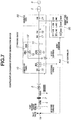
- FIG. 7 shows a single connection diagram of a water-turbine electricity-generating device using the permanent magnet power generator, and the water-turbine electricity-generating device is interconnected to an electric power system 6 through an interconnection transformer 5.
- Numeral 1 denotes a water turbine
- numeral 2 denotes a flywheel
- numeral 3 denotes a permanent magnet power generator, which are coupled through bearings 4.
- Numeral 10 denotes a converter panel, and the converter panel is equipped with respective components including a first converter (inverter) 11, a second converter 12, a brake circuit for regenerative braking 13, a smoothing capacitor 14, a filter unit 15, electromagnetic switches 16, 17, and a breaker 18.
- Numeral 20 denotes a generator panel, which has a breaker 21 performing interconnection control with respect to the electric power system 6.
- Numeral 30 denotes a dummy resistor device, in which plural resistors 33 having different resistance values are connected through breakers 31 and electromagnetic switches 32 respectively.
- Numeral 40 denotes an upper control unit, and the control unit 40 inputs rotation signals of the permanent magnet power generator 3 detected by an encoder through the converter panel 10.
- the control unit 40 also outputs control commands such as an output of a speed command to the converter panel 10, an output of a valve-position command to an inlet valve 1a of the water turbine and an output of an input command to the dummy resistor device 30.
- the electricity-generating device using the permanent magnet power generator shown in Fig. 1 is publicly known by, for example, Patent Publication 1 and so on.
- the breaker 21 When the electricity-generating device shown in Fig. 7 is interconnected to the electric power system 6, the breaker 21 is turned on by outputting an interconnection/operation command from the generator panel 20, then, the breaker 18 and the electromagnetic switch 17 are turned on in the converter panel 10, thereby converting alternate current from the electric power system 6 into direct current by the converter 12 to charge the smoothing capacitor 14.
- the input command is outputted to the electromagnetic switch 16 at a point when the initial charge of the smoothing capacitor 14 is performed and the preparation for operation is completed.
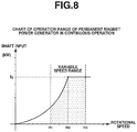
- the control unit 40 also outputs the speed command and a power factor command to the inverter 11 to operate the inverter 11, controlling the permanent magnet power generator 3 within an interconnection operation range to which dotted lines are given shown in Fig. 8 .
- the vertical axis indicates the shaft input of the permanent magnet power generator and the horizontal axis indicates the rotational speed.
- a rated capacity is f 0
- interconnection operation is performed while speeds n 1 , n 2 around a rated speed n 0 form the operation range of the permanent magnet power generator.
- the small and medium-scaled electricity-generating device is operated by being interconnected to the electric power system
- the interconnecting electricity-generating device has to be stopped when the autonomous operation function is not provided.
- the autonomous operation can be realized by specially adding the dummy resistor device or a high-speed guide vane control unit by an electric servo motor and so on to the electricity-generating device.
- it is necessary to add a peculiar operation function in that case which is disadvantageous in aspects of an installation place and costs.
- Patent Publication 1 Japanese Patent No. 4003414
- the present invention is directed to a method for an autonomous operation of an electricity-generating device including a permanent magnet power generator coupled to an energy source, first and second converters having forward/inverse conversion functions, a smoothing capacitor connecting to a DC linkage unit between the first and second converters and a control unit outputting control commands to the first and second converters, in which the electricity-generating device is operated along an efficiency-characteristics curve within a speed range from a rated speed to a maximum speed in the efficiency-characteristics curve of the energy source at the time of the autonomous operation of the electricity-generating device.
- a load to the electricity-generating device is connected and disconnected.
- the energy source is a water turbine
- a valve-position command is outputted to an inlet valve of the water turbine and the first converter is operated in a converter mode when an operation preparation command is outputted by the control unit, the second converter is operated in an inverter mode when a voltage is established by the DC linkage unit, and the load is connected when the operation preparation is completed.
- the efficiency-characteristics curve corresponding to the aperture of the inlet valve of the water turbine is used.
- the autonomous operation of the electricity-generating device is realized with the energy balance corresponding to the load within a speed range of the rated speed or more in the efficiency-characteristics curve. Accordingly, even when it is difficult for the electricity-generating device to perform system interconnection, the autonomous operation control can be performed without specially preparing a device for an isolated operation such as a dummy resistor device or a high-speed guide vane control unit by an electric servo motor.
- Fig. 1 is a schematic diagram showing an electricity-generating device according to the present Embodiment 1.
- Fig. 1 differs from Fig. 7 which shows a conventional electricity-generating device in a point that a dummy load device is omitted. Other points are the same as Fig. 7 , therefore, explanation will be omitted.
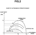
- Fig. 2 shows efficiency-characteristics curves (hereinafter referred to as Cp characteristics curves) of a water turbine.
- Cp characteristics curves efficiency-characteristics curves
- the autonomous operation is performed with respect to the load capacity which is lower than a rated capacity of the permanent magnet power generator in the case where the system interconnection is difficult to be performed.
- a Cp characteristics curve at an aperture 100% of the line A is used as well as a range in which the speed is the rated speed n 0 or higher is used as a variable speed range as shown in Fig. 3 .
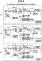
- a method for the autonomous operation will be explained with reference to Fig. 4 to Fig. 6 .
- components in an operation state are shown by being hatched.
- Fig. 4 (1) to Fig. 6 (3) correspond to the outline showing an operation procedure in the autonomous operation by the electricity-generating device shown in Fig. 1 .
- a DC control power supply is connected to a converter panel 10 in the initial state of the electricity-generating device.
- the inlet valve 1a of the water turbine 1 is in a closed state at this time.
- a valve-position command to the inlet valve 1a, input of an electromagnetic switch 16 and an operation preparation command for a first converter (inverter) 11 are outputted from an upper control unit 40. Accordingly, the water turbine 1 starts to rotate and a permanent magnet power generator 3 starts to generate power and generate a voltage.
- the initial charge to a smoothing capacitor 14 is started by the first converter (inverter) 11 being operated in a converter mode.
- Fig. 4 (3) the flow rate is increased as the aperture of the inlet valve 1a further progresses, and the water turbine 1 is accelerated into a runway speed (the rated speed n 0 or higher).
- the charging to the smoothing capacitor 14 further progresses accordingly, and an electromagnetic switch 17 and a breaker 18 are inputted at the time when a voltage in a DC linkage unit is established.
- Fig. 5 (1) the water turbine is at the runway speed at the aperture 100% of the inlet valve 1a, an output voltage is set and an output frequency is set with respect to a second converter 12, and the second converter 12 is allowed to have a function of automatically controlling voltage/frequency as an inverter operation to complete the operation preparation.
- the water turbine rotates at a maximum rotational speed n m shown in Fig. 3 .
- numerals inside square frames correspond to numerals in diagrams of Fig. 4 to Fig. 6 .
- a load input command in a power plant is issued with respect to a breaker CB1 from the upper control unit 40, thereby starting the autonomous operation.
- the load is inputted, a load current flows and the voltage in the DC linkage unit is reduced.
- the first converter (inverter) 11 controls the voltage in the DC linkage unit to be constant (AVR), thereby replenishing deficit of energy with rotation energy of the water turbine 1, a flywheel 2 and the permanent magnet power generator 3 as a rotating body and reducing the speed of the permanent magnet power generator 3 and the water turbine.
- AVR constant
- the rotational speed is reduced along the Cp characteristics curve from the maximum rotational speed n m , and the device is operated at a rotational speed of n m-1 which corresponds to the load.
- the rotational speed of the water turbine is further reduced in accordance with the inputted load amount, and the device is operated at a rotational speed of n m-2 .
- the range in which the load amount can be inputted is within a range of speed from the rated speed n 0 to the maximum speed n m .
- the rotational speed of the water turbine 1 at the time of the autonomous operation has to be the rated speed n 0 or more.
- the reason is that the rotational speed is reduced due to the overload and the rotation is finally stopped when operated at the rated speed n 0 or less.
- a stop command is outputted to the second converter 12 and the operation is stopped. After that, a stop command for the electricity-generating device is outputted and the first converter 11 is also stopped, then, a deceleration command is outputted to the inlet valve 1a of the water turbine and the inlet valve 1a is wholly closed to thereby stop the water turbine.
- the autonomous operation of the electricity-generating device is realized by performing operation at a speed at which the energy balance corresponding to the load is achieved within a speed range of the rated speed or more in the Cp characteristics curve. Accordingly, when it is difficult for the electricity-generating device to perform system interconnection, the autonomous operation control can be performed only by allowing the electricity-generating device to have a software-based autonomous function by the device for interconnection operation without specially preparing devices for an isolated operation such as a dummy resistor device or a high-speed guide vane control unit by an electric servo motor.
Landscapes
- Engineering & Computer Science (AREA)
- Chemical & Material Sciences (AREA)
- Combustion & Propulsion (AREA)
- Mechanical Engineering (AREA)
- General Engineering & Computer Science (AREA)
- Power Engineering (AREA)
- Control Of Eletrric Generators (AREA)
Claims (2)
- Verfahren für einen autonomen Betrieb einer Elektrizität erzeugenden Vorrichtung, umfassend:einen Permanentmagnetleistungsgenerator (3), der mit einer Wasserturbine (1) gekoppelt ist;einen ersten und zweiten Umformer (11, 12), die Vorwärts-/Rückwärts-Umwandlungsfunktionen aufweisen;einen Glättungskondensator (14), der mit einer DC-Kopplungseinheit zwischen dem ersten und zweiten Umformer (11, 12) verbunden ist; undeine Steuereinheit (40), die Steueranweisungen an den ersten und zweiten Umformer (11, 12) ausgibt,wobei, wenn der autonome Betrieb der Elektrizität erzeugenden Vorrichtung durchgeführt wird,der erste Umformer (11) eine Spannung der DC-Kopplungseinheit so steuert, dass sie konstant ist,eine mit der Elektrizität erzeugenden Vorrichtung verbundene Last verbunden oder getrennt wird, unddie Elektrizität erzeugende Vorrichtung zusammen mit einer Wirkungsgradcharakteristikkurve betrieben wird, die einer Öffnung eines Einlassventils (1a) der Wasserturbine (1) entspricht und auf einem Welleneingang und einer Drehzahl innerhalb eines Drehzahlbereiches von einer Nenndrehzahl (n0), bei der der Welleneingang der Wirkungsgradcharakteristikkurve maximal wird, zu einer maximalen Drehzahl (nm), bei der der Welleneingang minimal wird, in der Wirkungsgradcharakteristikkurve der Wasserturbine (1) basiert.
- Verfahren für den autonomen Betrieb der Elektrizität erzeugenden Vorrichtung nach Anspruch 1,
wobei während des autonomen Betriebs eine Ventilpositionsanweisung an das Einlassventil (1a) der Wasserturbine (1) ausgegeben wird und der erste Umformer (11) in einem Umformermodus betrieben wird, wenn eine Betriebsvorbereitungsanweisung von der Steuereinheit (40) ausgegeben wird, und
wobei der zweite Umformer (12) in einem Wechselrichtermodus betrieben wird, wenn eine Spannung durch die DC-Kupplungseinheit hergestellt wird und die Last verbunden ist, wenn die Betriebsvorbereitung vollständig ist.
Applications Claiming Priority (2)
| Application Number | Priority Date | Filing Date | Title |
|---|---|---|---|
| JP2014152468 | 2014-07-28 | ||
| PCT/JP2015/071179 WO2016017559A1 (ja) | 2014-07-28 | 2015-07-27 | 発電装置の自立運転方法 |
Publications (3)
| Publication Number | Publication Date |
|---|---|
| EP3174193A1 EP3174193A1 (de) | 2017-05-31 |
| EP3174193A4 EP3174193A4 (de) | 2018-07-11 |
| EP3174193B1 true EP3174193B1 (de) | 2019-09-11 |
Family
ID=55217460
Family Applications (1)
| Application Number | Title | Priority Date | Filing Date |
|---|---|---|---|
| EP15826870.6A Active EP3174193B1 (de) | 2014-07-28 | 2015-07-27 | Verfahren für den autonomen betrieb einer stromerzeugenden vorrichtung |
Country Status (5)
| Country | Link |
|---|---|
| US (1) | US10511242B2 (de) |
| EP (1) | EP3174193B1 (de) |
| JP (1) | JP6048595B2 (de) |
| CN (1) | CN106575935B (de) |
| WO (1) | WO2016017559A1 (de) |
Families Citing this family (2)
| Publication number | Priority date | Publication date | Assignee | Title |
|---|---|---|---|---|
| KR101961143B1 (ko) * | 2017-01-06 | 2019-03-25 | 엘지전자 주식회사 | 발전 시스템 및 발전 시스템의 발전기 제동 방법 |
| WO2019013775A1 (en) | 2017-07-12 | 2019-01-17 | Hewlett-Packard Development Company, L.P. | MIGRATION OF MEMORY DEVICES |
Family Cites Families (19)
| Publication number | Priority date | Publication date | Assignee | Title |
|---|---|---|---|---|
| US1983917A (en) * | 1931-03-07 | 1934-12-11 | Bbc Brown Boveri & Cie | Method of controlling electric drives for ships |
| JPS5735166A (en) * | 1980-08-13 | 1982-02-25 | Hitachi Ltd | Control method and unit for water turbine operation |
| JPS57212374A (en) * | 1981-06-22 | 1982-12-27 | Toshiba Corp | Method of operating multi-stage hydraulic machine |
| JPS58140482A (ja) * | 1982-02-17 | 1983-08-20 | Hitachi Ltd | 多段水力機械の運転制御方法 |
| JPS59192868A (ja) * | 1983-04-14 | 1984-11-01 | Toshiba Corp | 多段ポンプ水車の保護制御方法 |
| JP2631373B2 (ja) * | 1987-08-20 | 1997-07-16 | 株式会社日立製作所 | 可変速揚水発電システムの運転制御装置 |
| PT947042E (pt) * | 1996-12-20 | 2002-04-29 | Manuel Dos Santos Da Ponte | Aparelho gerador hibrido |
| NL1010800C2 (nl) | 1998-12-14 | 2000-06-19 | Lagerwey Windturbine B V | Werkwijze en inrichting voor het omzetten van een fluïdumstroom met wisselende sterkte in elektrische energie. |
| JP4003414B2 (ja) * | 2001-06-29 | 2007-11-07 | 株式会社日立製作所 | 永久磁石式発電機を用いた発電装置 |
| JP4365394B2 (ja) | 2006-09-20 | 2009-11-18 | 株式会社日立製作所 | 風力発電システムおよびその運転方法 |
| CN101291068B (zh) | 2007-04-18 | 2012-06-20 | 上海御能动力科技有限公司 | 一种发电功率全控并网式风力发电驱动系统 |
| JP5198791B2 (ja) * | 2007-05-07 | 2013-05-15 | 株式会社日立製作所 | 風力発電システム及びその制御方法及びこれを用いた風力発電所 |
| DE102008053732B8 (de) | 2008-10-29 | 2013-10-02 | Voith Patent Gmbh | Verfahren und Vorrichtung für die Leistungsregelung eines Unterwasserkraftwerks |
| JP5584592B2 (ja) * | 2010-11-04 | 2014-09-03 | 大阪瓦斯株式会社 | 発電システムの制御方法及びその制御装置 |
| CA2780451A1 (en) * | 2011-06-21 | 2012-12-21 | Genalta Power, Inc. | Variable speed power generation from industrial fluid energy sources |
| GB2493711B (en) | 2011-08-12 | 2018-04-25 | Openhydro Ip Ltd | Method and system for controlling hydroelectric turbines |
| JP6109528B2 (ja) * | 2012-10-29 | 2017-04-05 | 京セラ株式会社 | 電力制御装置および電力制御方法 |
| JP6037803B2 (ja) * | 2012-11-30 | 2016-12-07 | 三菱重工業株式会社 | 風車及びその制御方法並びに風力発電システム |
| CN103306886B (zh) * | 2013-05-29 | 2016-03-30 | 郑程遥 | 一种水轮发电机组的全参数调节控制方法 |
-
2015
- 2015-07-27 WO PCT/JP2015/071179 patent/WO2016017559A1/ja not_active Ceased
- 2015-07-27 CN CN201580040691.0A patent/CN106575935B/zh active Active
- 2015-07-27 US US15/328,667 patent/US10511242B2/en active Active
- 2015-07-27 EP EP15826870.6A patent/EP3174193B1/de active Active
- 2015-07-27 JP JP2015555319A patent/JP6048595B2/ja active Active
Non-Patent Citations (1)
| Title |
|---|
| None * |
Also Published As
| Publication number | Publication date |
|---|---|
| EP3174193A1 (de) | 2017-05-31 |
| CN106575935B (zh) | 2019-03-08 |
| WO2016017559A1 (ja) | 2016-02-04 |
| CN106575935A (zh) | 2017-04-19 |
| EP3174193A4 (de) | 2018-07-11 |
| JP6048595B2 (ja) | 2016-12-21 |
| US20170214348A1 (en) | 2017-07-27 |
| US10511242B2 (en) | 2019-12-17 |
| JPWO2016017559A1 (ja) | 2017-04-27 |
Similar Documents
| Publication | Publication Date | Title |
|---|---|---|
| EP2416475B1 (de) | Elektrisches Stromerzeugungssystem mit Aufwärtswandler/synchronem Aktivfilter | |
| EP3086432B1 (de) | Stromverteilungssysteme | |
| EP2197095A2 (de) | Leistungswandler | |
| US10519933B2 (en) | Method of operating a wind turbine system including an energy storage system | |
| CN106208071B (zh) | 混合式ac及dc分配系统和使用方法 | |
| US10523088B2 (en) | Energy storage system for doubly fed induction generator | |
| JP2014023421A (ja) | 風力発電システム及びその励磁同期発電機の制御方法 | |
| CN110249494B (zh) | 移动体的配电系统 | |
| EP3579400B1 (de) | System und verfahren zur minimierung des zustroms während des startvorgangs eines stromsystems | |
| EP3174193B1 (de) | Verfahren für den autonomen betrieb einer stromerzeugenden vorrichtung | |
| CN105720679A (zh) | 一种混合型岸电变频电源供电系统 | |
| JP6586828B2 (ja) | 水車加速抑制方法とその装置 | |
| EP3639341B1 (de) | Stromuntersysteme und verfahren zur steuerung davon | |
| CN120548408A (zh) | 飞行器涡轮发动机的高压体和低压体之间的功率传输 | |
| US20240093670A1 (en) | Operating a wind turbine in an off-grid stand-alone mode | |
| WO2016167816A1 (en) | Dynamic wind turbine energy storage device | |
| EP4269787A1 (de) | Stromversorgung einer zusatzwindturbinenanlage | |
| JP2016125456A (ja) | 風力発電装置 | |
| JP2016131442A (ja) | 小水力可変速発電システムの自立運転装置 |
Legal Events
| Date | Code | Title | Description |
|---|---|---|---|
| STAA | Information on the status of an ep patent application or granted ep patent |
Free format text: STATUS: THE INTERNATIONAL PUBLICATION HAS BEEN MADE |
|
| PUAI | Public reference made under article 153(3) epc to a published international application that has entered the european phase |
Free format text: ORIGINAL CODE: 0009012 |
|
| STAA | Information on the status of an ep patent application or granted ep patent |
Free format text: STATUS: REQUEST FOR EXAMINATION WAS MADE |
|
| 17P | Request for examination filed |
Effective date: 20170227 |
|
| AK | Designated contracting states |
Kind code of ref document: A1 Designated state(s): AL AT BE BG CH CY CZ DE DK EE ES FI FR GB GR HR HU IE IS IT LI LT LU LV MC MK MT NL NO PL PT RO RS SE SI SK SM TR |
|
| AX | Request for extension of the european patent |
Extension state: BA ME |
|
| DAV | Request for validation of the european patent (deleted) | ||
| DAX | Request for extension of the european patent (deleted) | ||
| A4 | Supplementary search report drawn up and despatched |
Effective date: 20180611 |
|
| RIC1 | Information provided on ipc code assigned before grant |
Ipc: H02J 3/38 20060101ALN20180605BHEP Ipc: F03B 15/04 20060101ALI20180605BHEP Ipc: F03B 15/00 20060101ALI20180605BHEP Ipc: H02P 9/04 20060101AFI20180605BHEP |
|
| RIC1 | Information provided on ipc code assigned before grant |
Ipc: H02P 9/04 20060101AFI20190214BHEP Ipc: H02J 3/38 20060101ALN20190214BHEP Ipc: F03B 15/04 20060101ALI20190214BHEP Ipc: H02K 7/18 20060101ALI20190214BHEP Ipc: F03B 15/00 20060101ALI20190214BHEP Ipc: F03B 15/06 20060101ALI20190214BHEP |
|
| GRAP | Despatch of communication of intention to grant a patent |
Free format text: ORIGINAL CODE: EPIDOSNIGR1 |
|
| STAA | Information on the status of an ep patent application or granted ep patent |
Free format text: STATUS: GRANT OF PATENT IS INTENDED |
|
| RIC1 | Information provided on ipc code assigned before grant |
Ipc: H02J 3/38 20060101ALN20190307BHEP Ipc: H02P 9/04 20060101AFI20190307BHEP Ipc: F03B 15/06 20060101ALI20190307BHEP Ipc: F03B 15/00 20060101ALI20190307BHEP Ipc: F03B 15/04 20060101ALI20190307BHEP Ipc: H02K 7/18 20060101ALI20190307BHEP |
|
| RIC1 | Information provided on ipc code assigned before grant |
Ipc: H02K 7/18 20060101ALI20190311BHEP Ipc: F03B 15/00 20060101ALI20190311BHEP Ipc: F03B 15/06 20060101ALI20190311BHEP Ipc: F03B 15/04 20060101ALI20190311BHEP Ipc: H02J 3/38 20060101ALN20190311BHEP Ipc: H02P 9/04 20060101AFI20190311BHEP |
|
| INTG | Intention to grant announced |
Effective date: 20190327 |
|
| GRAS | Grant fee paid |
Free format text: ORIGINAL CODE: EPIDOSNIGR3 |
|
| GRAA | (expected) grant |
Free format text: ORIGINAL CODE: 0009210 |
|
| STAA | Information on the status of an ep patent application or granted ep patent |
Free format text: STATUS: THE PATENT HAS BEEN GRANTED |
|
| AK | Designated contracting states |
Kind code of ref document: B1 Designated state(s): AL AT BE BG CH CY CZ DE DK EE ES FI FR GB GR HR HU IE IS IT LI LT LU LV MC MK MT NL NO PL PT RO RS SE SI SK SM TR |
|
| REG | Reference to a national code |
Ref country code: GB Ref legal event code: FG4D |
|
| REG | Reference to a national code |
Ref country code: CH Ref legal event code: EP |
|
| REG | Reference to a national code |
Ref country code: AT Ref legal event code: REF Ref document number: 1179802 Country of ref document: AT Kind code of ref document: T Effective date: 20190915 |
|
| REG | Reference to a national code |
Ref country code: DE Ref legal event code: R096 Ref document number: 602015037957 Country of ref document: DE |
|
| REG | Reference to a national code |
Ref country code: IE Ref legal event code: FG4D |
|
| REG | Reference to a national code |
Ref country code: NL Ref legal event code: MP Effective date: 20190911 |
|
| REG | Reference to a national code |
Ref country code: LT Ref legal event code: MG4D |
|
| PG25 | Lapsed in a contracting state [announced via postgrant information from national office to epo] |
Ref country code: LT Free format text: LAPSE BECAUSE OF FAILURE TO SUBMIT A TRANSLATION OF THE DESCRIPTION OR TO PAY THE FEE WITHIN THE PRESCRIBED TIME-LIMIT Effective date: 20190911 Ref country code: FI Free format text: LAPSE BECAUSE OF FAILURE TO SUBMIT A TRANSLATION OF THE DESCRIPTION OR TO PAY THE FEE WITHIN THE PRESCRIBED TIME-LIMIT Effective date: 20190911 Ref country code: BG Free format text: LAPSE BECAUSE OF FAILURE TO SUBMIT A TRANSLATION OF THE DESCRIPTION OR TO PAY THE FEE WITHIN THE PRESCRIBED TIME-LIMIT Effective date: 20191211 Ref country code: NO Free format text: LAPSE BECAUSE OF FAILURE TO SUBMIT A TRANSLATION OF THE DESCRIPTION OR TO PAY THE FEE WITHIN THE PRESCRIBED TIME-LIMIT Effective date: 20191211 Ref country code: SE Free format text: LAPSE BECAUSE OF FAILURE TO SUBMIT A TRANSLATION OF THE DESCRIPTION OR TO PAY THE FEE WITHIN THE PRESCRIBED TIME-LIMIT Effective date: 20190911 Ref country code: HR Free format text: LAPSE BECAUSE OF FAILURE TO SUBMIT A TRANSLATION OF THE DESCRIPTION OR TO PAY THE FEE WITHIN THE PRESCRIBED TIME-LIMIT Effective date: 20190911 |
|
| PG25 | Lapsed in a contracting state [announced via postgrant information from national office to epo] |
Ref country code: GR Free format text: LAPSE BECAUSE OF FAILURE TO SUBMIT A TRANSLATION OF THE DESCRIPTION OR TO PAY THE FEE WITHIN THE PRESCRIBED TIME-LIMIT Effective date: 20191212 Ref country code: LV Free format text: LAPSE BECAUSE OF FAILURE TO SUBMIT A TRANSLATION OF THE DESCRIPTION OR TO PAY THE FEE WITHIN THE PRESCRIBED TIME-LIMIT Effective date: 20190911 Ref country code: RS Free format text: LAPSE BECAUSE OF FAILURE TO SUBMIT A TRANSLATION OF THE DESCRIPTION OR TO PAY THE FEE WITHIN THE PRESCRIBED TIME-LIMIT Effective date: 20190911 Ref country code: AL Free format text: LAPSE BECAUSE OF FAILURE TO SUBMIT A TRANSLATION OF THE DESCRIPTION OR TO PAY THE FEE WITHIN THE PRESCRIBED TIME-LIMIT Effective date: 20190911 Ref country code: ES Free format text: LAPSE BECAUSE OF FAILURE TO SUBMIT A TRANSLATION OF THE DESCRIPTION OR TO PAY THE FEE WITHIN THE PRESCRIBED TIME-LIMIT Effective date: 20190911 |
|
| REG | Reference to a national code |
Ref country code: AT Ref legal event code: MK05 Ref document number: 1179802 Country of ref document: AT Kind code of ref document: T Effective date: 20190911 |
|
| PG25 | Lapsed in a contracting state [announced via postgrant information from national office to epo] |
Ref country code: NL Free format text: LAPSE BECAUSE OF FAILURE TO SUBMIT A TRANSLATION OF THE DESCRIPTION OR TO PAY THE FEE WITHIN THE PRESCRIBED TIME-LIMIT Effective date: 20190911 Ref country code: AT Free format text: LAPSE BECAUSE OF FAILURE TO SUBMIT A TRANSLATION OF THE DESCRIPTION OR TO PAY THE FEE WITHIN THE PRESCRIBED TIME-LIMIT Effective date: 20190911 Ref country code: EE Free format text: LAPSE BECAUSE OF FAILURE TO SUBMIT A TRANSLATION OF THE DESCRIPTION OR TO PAY THE FEE WITHIN THE PRESCRIBED TIME-LIMIT Effective date: 20190911 Ref country code: PL Free format text: LAPSE BECAUSE OF FAILURE TO SUBMIT A TRANSLATION OF THE DESCRIPTION OR TO PAY THE FEE WITHIN THE PRESCRIBED TIME-LIMIT Effective date: 20190911 Ref country code: PT Free format text: LAPSE BECAUSE OF FAILURE TO SUBMIT A TRANSLATION OF THE DESCRIPTION OR TO PAY THE FEE WITHIN THE PRESCRIBED TIME-LIMIT Effective date: 20200113 Ref country code: IT Free format text: LAPSE BECAUSE OF FAILURE TO SUBMIT A TRANSLATION OF THE DESCRIPTION OR TO PAY THE FEE WITHIN THE PRESCRIBED TIME-LIMIT Effective date: 20190911 Ref country code: RO Free format text: LAPSE BECAUSE OF FAILURE TO SUBMIT A TRANSLATION OF THE DESCRIPTION OR TO PAY THE FEE WITHIN THE PRESCRIBED TIME-LIMIT Effective date: 20190911 |
|
| PG25 | Lapsed in a contracting state [announced via postgrant information from national office to epo] |
Ref country code: SM Free format text: LAPSE BECAUSE OF FAILURE TO SUBMIT A TRANSLATION OF THE DESCRIPTION OR TO PAY THE FEE WITHIN THE PRESCRIBED TIME-LIMIT Effective date: 20190911 Ref country code: CZ Free format text: LAPSE BECAUSE OF FAILURE TO SUBMIT A TRANSLATION OF THE DESCRIPTION OR TO PAY THE FEE WITHIN THE PRESCRIBED TIME-LIMIT Effective date: 20190911 Ref country code: IS Free format text: LAPSE BECAUSE OF FAILURE TO SUBMIT A TRANSLATION OF THE DESCRIPTION OR TO PAY THE FEE WITHIN THE PRESCRIBED TIME-LIMIT Effective date: 20200224 Ref country code: SK Free format text: LAPSE BECAUSE OF FAILURE TO SUBMIT A TRANSLATION OF THE DESCRIPTION OR TO PAY THE FEE WITHIN THE PRESCRIBED TIME-LIMIT Effective date: 20190911 |
|
| REG | Reference to a national code |
Ref country code: DE Ref legal event code: R097 Ref document number: 602015037957 Country of ref document: DE |
|
| PLBE | No opposition filed within time limit |
Free format text: ORIGINAL CODE: 0009261 |
|
| STAA | Information on the status of an ep patent application or granted ep patent |
Free format text: STATUS: NO OPPOSITION FILED WITHIN TIME LIMIT |
|
| PG2D | Information on lapse in contracting state deleted |
Ref country code: IS |
|
| PG25 | Lapsed in a contracting state [announced via postgrant information from national office to epo] |
Ref country code: DK Free format text: LAPSE BECAUSE OF FAILURE TO SUBMIT A TRANSLATION OF THE DESCRIPTION OR TO PAY THE FEE WITHIN THE PRESCRIBED TIME-LIMIT Effective date: 20190911 Ref country code: IS Free format text: LAPSE BECAUSE OF FAILURE TO SUBMIT A TRANSLATION OF THE DESCRIPTION OR TO PAY THE FEE WITHIN THE PRESCRIBED TIME-LIMIT Effective date: 20200112 |
|
| 26N | No opposition filed |
Effective date: 20200615 |
|
| PG25 | Lapsed in a contracting state [announced via postgrant information from national office to epo] |
Ref country code: SI Free format text: LAPSE BECAUSE OF FAILURE TO SUBMIT A TRANSLATION OF THE DESCRIPTION OR TO PAY THE FEE WITHIN THE PRESCRIBED TIME-LIMIT Effective date: 20190911 |
|
| PG25 | Lapsed in a contracting state [announced via postgrant information from national office to epo] |
Ref country code: MC Free format text: LAPSE BECAUSE OF FAILURE TO SUBMIT A TRANSLATION OF THE DESCRIPTION OR TO PAY THE FEE WITHIN THE PRESCRIBED TIME-LIMIT Effective date: 20190911 |
|
| REG | Reference to a national code |
Ref country code: CH Ref legal event code: PL |
|
| GBPC | Gb: european patent ceased through non-payment of renewal fee |
Effective date: 20200727 |
|
| REG | Reference to a national code |
Ref country code: BE Ref legal event code: MM Effective date: 20200731 |
|
| PG25 | Lapsed in a contracting state [announced via postgrant information from national office to epo] |
Ref country code: GB Free format text: LAPSE BECAUSE OF NON-PAYMENT OF DUE FEES Effective date: 20200727 Ref country code: CH Free format text: LAPSE BECAUSE OF NON-PAYMENT OF DUE FEES Effective date: 20200731 Ref country code: FR Free format text: LAPSE BECAUSE OF NON-PAYMENT OF DUE FEES Effective date: 20200731 Ref country code: LU Free format text: LAPSE BECAUSE OF NON-PAYMENT OF DUE FEES Effective date: 20200727 Ref country code: LI Free format text: LAPSE BECAUSE OF NON-PAYMENT OF DUE FEES Effective date: 20200731 |
|
| PG25 | Lapsed in a contracting state [announced via postgrant information from national office to epo] |
Ref country code: BE Free format text: LAPSE BECAUSE OF NON-PAYMENT OF DUE FEES Effective date: 20200731 |
|
| PG25 | Lapsed in a contracting state [announced via postgrant information from national office to epo] |
Ref country code: IE Free format text: LAPSE BECAUSE OF NON-PAYMENT OF DUE FEES Effective date: 20200727 |
|
| PG25 | Lapsed in a contracting state [announced via postgrant information from national office to epo] |
Ref country code: TR Free format text: LAPSE BECAUSE OF FAILURE TO SUBMIT A TRANSLATION OF THE DESCRIPTION OR TO PAY THE FEE WITHIN THE PRESCRIBED TIME-LIMIT Effective date: 20190911 Ref country code: MT Free format text: LAPSE BECAUSE OF FAILURE TO SUBMIT A TRANSLATION OF THE DESCRIPTION OR TO PAY THE FEE WITHIN THE PRESCRIBED TIME-LIMIT Effective date: 20190911 Ref country code: CY Free format text: LAPSE BECAUSE OF FAILURE TO SUBMIT A TRANSLATION OF THE DESCRIPTION OR TO PAY THE FEE WITHIN THE PRESCRIBED TIME-LIMIT Effective date: 20190911 |
|
| PG25 | Lapsed in a contracting state [announced via postgrant information from national office to epo] |
Ref country code: MK Free format text: LAPSE BECAUSE OF FAILURE TO SUBMIT A TRANSLATION OF THE DESCRIPTION OR TO PAY THE FEE WITHIN THE PRESCRIBED TIME-LIMIT Effective date: 20190911 |
|
| PGFP | Annual fee paid to national office [announced via postgrant information from national office to epo] |
Ref country code: DE Payment date: 20250722 Year of fee payment: 11 |