EP3174571B1 - Dispositif de détection du sens de l'écoulement du liquide à travers un dialyseur - Google Patents
Dispositif de détection du sens de l'écoulement du liquide à travers un dialyseur Download PDFInfo
- Publication number
- EP3174571B1 EP3174571B1 EP15739286.1A EP15739286A EP3174571B1 EP 3174571 B1 EP3174571 B1 EP 3174571B1 EP 15739286 A EP15739286 A EP 15739286A EP 3174571 B1 EP3174571 B1 EP 3174571B1
- Authority
- EP
- European Patent Office
- Prior art keywords
- clearance
- flow
- dialysate
- blood
- change
- Prior art date
- Legal status (The legal status is an assumption and is not a legal conclusion. Google has not performed a legal analysis and makes no representation as to the accuracy of the status listed.)
- Active
Links
Images

Classifications
-
- A—HUMAN NECESSITIES
- A61—MEDICAL OR VETERINARY SCIENCE; HYGIENE
- A61M—DEVICES FOR INTRODUCING MEDIA INTO, OR ONTO, THE BODY; DEVICES FOR TRANSDUCING BODY MEDIA OR FOR TAKING MEDIA FROM THE BODY; DEVICES FOR PRODUCING OR ENDING SLEEP OR STUPOR
- A61M1/00—Suction or pumping devices for medical purposes; Devices for carrying-off, for treatment of, or for carrying-over, body-liquids; Drainage systems
- A61M1/14—Dialysis systems; Artificial kidneys; Blood oxygenators ; Reciprocating systems for treatment of body fluids, e.g. single needle systems for hemofiltration or pheresis
- A61M1/16—Dialysis systems; Artificial kidneys; Blood oxygenators ; Reciprocating systems for treatment of body fluids, e.g. single needle systems for hemofiltration or pheresis with membranes
- A61M1/1601—Control or regulation
- A61M1/1603—Regulation parameters
- A61M1/1605—Physical characteristics of the dialysate fluid
- A61M1/1609—Physical characteristics of the dialysate fluid after use, i.e. downstream of dialyser
-
- A—HUMAN NECESSITIES
- A61—MEDICAL OR VETERINARY SCIENCE; HYGIENE
- A61M—DEVICES FOR INTRODUCING MEDIA INTO, OR ONTO, THE BODY; DEVICES FOR TRANSDUCING BODY MEDIA OR FOR TAKING MEDIA FROM THE BODY; DEVICES FOR PRODUCING OR ENDING SLEEP OR STUPOR
- A61M1/00—Suction or pumping devices for medical purposes; Devices for carrying-off, for treatment of, or for carrying-over, body-liquids; Drainage systems
- A61M1/14—Dialysis systems; Artificial kidneys; Blood oxygenators ; Reciprocating systems for treatment of body fluids, e.g. single needle systems for hemofiltration or pheresis
- A61M1/16—Dialysis systems; Artificial kidneys; Blood oxygenators ; Reciprocating systems for treatment of body fluids, e.g. single needle systems for hemofiltration or pheresis with membranes
- A61M1/1601—Control or regulation
- A61M1/1615—Control or regulation using measurements made at different flow rates
-
- A—HUMAN NECESSITIES
- A61—MEDICAL OR VETERINARY SCIENCE; HYGIENE
- A61M—DEVICES FOR INTRODUCING MEDIA INTO, OR ONTO, THE BODY; DEVICES FOR TRANSDUCING BODY MEDIA OR FOR TAKING MEDIA FROM THE BODY; DEVICES FOR PRODUCING OR ENDING SLEEP OR STUPOR
- A61M1/00—Suction or pumping devices for medical purposes; Devices for carrying-off, for treatment of, or for carrying-over, body-liquids; Drainage systems
- A61M1/14—Dialysis systems; Artificial kidneys; Blood oxygenators ; Reciprocating systems for treatment of body fluids, e.g. single needle systems for hemofiltration or pheresis
- A61M1/16—Dialysis systems; Artificial kidneys; Blood oxygenators ; Reciprocating systems for treatment of body fluids, e.g. single needle systems for hemofiltration or pheresis with membranes
- A61M1/1601—Control or regulation
- A61M1/1617—Control or regulation using measurements made during a temporary variation of a characteristic of the fresh dialysis fluid
Definitions
- the invention relates to a device for detecting the direction of liquid flow through a dialyzer, which has a blood chamber through which flows blood and a dialysis fluid flowed through by dialysis fluid, which are separated from each other by a semipermeable membrane.
- the invention relates to an extracorporeal blood treatment device having an extracorporeal blood circuit including the blood chamber of a dialyzer divided by a semipermeable membrane into the blood chamber and a dialysis fluid chamber, and to a fluid system including the dialysis fluid chamber of the dialyzer, the extracorporeal blood treatment device comprising a device for Detection of the direction of liquid flow through the dialyzer has.
- the known blood treatment devices include, for example, the devices for hemodialysis, hemofiltration and hemodiafiltration.
- the blood treatment unit is a dialyzer or filter which is separated by a semipermeable membrane into a blood chamber and a dialysis fluid chamber.
- the blood flows through the blood chamber while the dialysis fluid flows through the dialysis fluid chamber.
- Effective blood treatment requires that blood and dialysis fluid flow in opposite directions along the membrane of the dialyzer or filter. With the same flow direction, the blood treatment is less effective.
- the dialyzer or filter is not operated in DC, but countercurrent.
- a reduced dialysis efficiency may be desirable, for example to avoid a disequilibrium syndrome.
- operation may be in cocurrent if the dialysis efficiency is not reduced by a change in blood flow or dialysis fluid flow.
- a DC connection can be an advantage.
- a known quantity for indicating the effectiveness of a dialysis treatment is the clearance K.
- the clearance K of a substance is the partial flow of the total flow through the dialyzer, which is completely freed from the substance concerned.
- the so-called dialysis dose KT / V is crucial, which is defined as the quotient of the product of clearance K for urea and effective treatment time T of the dialysis treatment and the volume of distribution V of the patient for urea.
- the known dialysis machines allow the manual setting of different dialysis fluid rates, for example 300, 500 and 800 ml / min. To achieve a high clearance, higher dialysate flows are generally required for higher blood flows.
- the dialyzer or filter of a blood treatment device is a replaceable unit that is connected to the fluid system of the dialysis machine.
- the fluid system of the known blood treatment devices comprises a line system with a first and a second line section for the connection of the dialyzer.
- the first line section is connected to the inlet of the dialysis fluid chamber and the second line section is connected to the outlet of the dialysis fluid chamber of the dialyzer.
- the manufacturers of dialyzers and blood treatment devices provide a color coding of the line sections to be connected to the inlet and outlet on both the blood and dialysate side in order to facilitate the user's connection in counter or direct current.
- this color coding is not uniform for all manufacturers. Therefore, there is a risk that the connections are confused. This is referred to below as improper connection.
- improper connection The same applies to an automated reversal of the flow direction, for example by switching over a device provided in the extracorporeal blood circulation for reversing the flow or by reversing the delivery direction of the blood pump, since it can also lead to a faulty connection.
- the dialyzer is not operated in countercurrent, but direct current, the effectiveness of the blood treatment for the patient may not be sufficient. This is particularly problematic if an improper connection of the dialyzer should go unnoticed. Then there is a risk that the patient will be treated in the long run with insufficient effectiveness.
- the DE 10 2010 032 980 A1 describes a device for detecting the direction of liquid flow through a dialyzer based on the change of a physical and / or chemical property, for example the substance concentration, a liquid flowing into the blood chamber of the dialyzer and the measurement of the change in the physical and / or chemical property of is based on the blood chamber of the dialyzer flowing liquid.
- the change in physical and / or chemical property upstream of the blood chamber of the dialyzer due to the change in the physical and / or chemical property of the Liquid downstream of the blood chamber is measured before and after the reversal of the flow direction of the liquid through the blood chamber.
- a device for detecting an operating state of an extracorporeal blood treatment device which has a measuring unit for measuring the dialysis efficiency (clearance).
- the measurement of the clearance is based on the change in the properties of the fresh dialysate and the reaction in the spent dialysate at user-specified dialysis conditions, for example a given blood flow and dialysate flow.
- the US 2013 / 0338560A1 describes an extracorporeal blood treatment device having means for changing the flow direction of the blood flowing through the patient.
- the blood treatment apparatus has a device which allows a reversal of the blood flow in the conduit sections of the extracorporeal blood circulation which are connected to the patient by means of cannulas.
- the blood flows from the "arterial" cannula into the blood chamber of the dialyzer and out of the blood chamber of the dialyzer to the "venous" cannula, while the dialysis fluid flows in the opposite direction through the dialysis fluid chamber of the dialyzer.
- the invention has for its object to provide a device for detecting the direction of liquid flow through a dialyzer to check whether the dialyzer is operated in cocurrent or countercurrent.
- a first aspect of the invention is to measure the clearance or a characteristic clearance for the purpose of detecting the direction of fluid flow through the dialyzer and to compare the measured clearance or the measured characteristic of the clearance with a predetermined limit value closed the direction of flow of blood through the blood chamber and dialysis fluid through the dialysis fluid in countercurrent when the clearance or clearance characteristic size is greater than the predetermined threshold.
- This aspect is based on the finding that in a blood treatment in practice with an operation of the dialyzer in the DC clearance values above a certain threshold are no longer achievable. Therefore, for clearance values above a predetermined limit value, it is immediately possible to deduce countercurrent operation. Consequently, it can be recognized immediately whether the operation of the dialyzer, which is predominantly used in practice in countercurrent, is actually set. This increases the safety of the blood treatment.
- the predetermined limit value can be determined for a specific range in which changes in the dialysis fluid flow and / or blood flow are to be expected in practice.
- the mass transfer coefficients of the dialyzers used in practice can also be taken into account.
- the device For measuring the clearance or a characteristic size for the clearance, the device according to the invention has a measuring unit and for the comparison of the measured clearance with the predetermined limit value via an evaluation and arithmetic unit.
- the measuring unit and the evaluation and arithmetic unit can form independent units or be part of the measuring device and / or central control unit and / or arithmetic and evaluation unit (microprocessor) of the blood treatment device.
- a second aspect of the invention is to measure the clearance or a characteristic size for the detection of the flow direction and to change the flow rate of the dialysis fluid.
- the device according to the invention has a measuring unit for measuring the clearance or a characteristic size for clearance before and after the change of the dialysis fluid rate and a control unit for changing the flow rate of the dialysis fluid through the dialysis fluid chamber of the dialyzer by a predetermined amount.
- the device according to the invention according to the second aspect of the invention is based on the comparison of the change in the measured clearance or a characteristic size with a calculated expected value of the change in clearance or a characteristic size for the operation of the clearance Dialyzer in both countercurrent and in the DC. Actual operation of the dialyzer in countercurrent flow is then concluded when the measured value for the change in the clearance or the characteristic of the clearance is closer to the expected value for the change in the clearance or clearance characteristic of the countercurrent flow. Operation is considered to be for DC operation, while closing to actual operation of the dialyzer in cocurrent, when the measured value for the change in the clearance or, the characteristic of the clearance characteristic size closer to the expected value for the clearance or for the Clearance characteristic size for DC operation than for countercurrent operation is.
- the invention according to the second aspect is based on the finding that the amount of the relative change in clearance in the case of a change in the dialysis fluid rate during operation in direct current is always greater than in countercurrent.
- a measurement of the clearance also means the determination of the clearance when the clearance is calculated from measured quantities.
- the calculating and evaluating unit of the device according to the invention is configured such that on the basis of the change of the clearance or the size characteristic of the clearance, which is due to a change of the dialysis fluid rate by a predetermined amount, on the direction of the flow of blood through the Blood chamber and dialysis fluid through the dialysis fluid in countercurrent or DC is closed.
- a preferred embodiment of the invention provides that the amount of the expected change in the clearance, which is due to the change in the dialysis fluid rate, or the size characteristic of the clearance, on the basis of a characteristic of the clearance or clearance characteristic of the dialysate fluid ratio is calculated for a flow of the dialysis fluid in countercurrent and direct current, and that from the before and after the change of Dialysate fluid rate or clearance measured characteristic of the amount of actual change in clearance or characteristic of the clearance size is calculated. Based on a comparison of the amount of actual change in clearance or characteristic size with the expected value of change in clearance or clearance characteristic size for the countercurrent and DC, then a flow in countercurrent or direct current is inferred , For the comparison of the amount of the actual change and the calculated change of the clearance different evaluation methods can be used.
- the amount of the difference between the amount of the actual change in the clearance or the characteristic size and the expected value of the change in the clearance or the clearance characteristic size becomes the countercurrent and the amount of the difference between the amount the actual change in clearance or clearance characteristic size and the expected value of change in clearance or clearance characteristic size for the DC.
- DC flow is considered to be the case if the magnitude of the difference for the DC current is less than the magnitude of the difference for the countercurrent, while closing for countercurrent flow, if the magnitude of the difference for the countercurrent is less than the magnitude of the Difference for the DC is. Consequently, we tested whether the measured change in clearance is closer to the expected value for DC or countercurrent operation.
- the measuring unit for measuring the clearance or the characteristic size for clearance preferably has means for changing a physical and / or chemical property of the dialysis fluid flowing into the dialysis fluid chamber and means for measuring the physical and / or chemical property of the dialysis fluid flowing out of the dialysis fluid chamber.
- the physical and / or chemical property is preferably the concentration of a substance in the dialysis fluid, wherein the means for measuring the physical and / or chemical property are means for measuring the substance concentration.
- the means for measuring the physical and / or chemical property are means for measuring the substance concentration.
- the Na concentration is changed.
- the change in the amount of substance can easily be done in the dialysate preparation of the extracorporeal blood treatment device.
- the measurement of the concentration of a substance can be carried out with the known sensors, which are generally present anyway in the known blood treatment devices. Therefore, the device according to the invention can be easily implemented in the known blood treatment devices.
- the clearance can also be measured with a measuring unit which measures a characteristic characteristic of the clearance, for example the absorption of electromagnetic radiation in the blood, which can be in the UV range, visible range or IR range.
- a characteristic characteristic of the clearance for example the absorption of electromagnetic radiation in the blood, which can be in the UV range, visible range or IR range.
- a further preferred embodiment provides that after the flow direction has been determined, the arithmetic and evaluation unit generates a signal (data) which signals the operating state in countercurrent or a signal which indicates the operating state in direct current.
- This signal (data) can be transmitted to an external unit.
- the signal is transmitted to a display the operating state indicating unit.
- the signal may also be a control signal which the central control unit of the blood treatment device receives to perform an intervention in the machine control.
- the intervention in the machine control can be that the execution of the blood treatment is prevented. This ensures that blood treatment is only possible if the dialyzer is properly connected. However, it is also possible to reverse the flow direction as an intervention in the machine control, so that the dialyzer is then operated properly.
- the signal may also be an alarm signal to give an alarm in case of faulty connection of the dialyzer.
- the first and second aspects of the invention may be used as independent criteria for checking the flow direction or in combination. Preferably, both aspects are combined to check the flow direction.
- the verification according to the second aspect can serve to verify the verification according to the first aspect or vice versa.
- Fig. 1 shows in a highly simplified schematic representation only essential for the invention components of an extracorporeal blood treatment device.
- the device for detecting the direction of liquid flow through the dialyzer of the extracorporeal blood treatment device is part of the blood treatment device.
- the device for detecting the flow direction of the dialyzer can also form a separate unit.
- the extracorporeal blood treatment device which in the present embodiment is a hemodialysis device, has a dialyzer 1 separated by a semipermeable membrane 2 into a blood chamber 4 and a dialysis fluid chamber 3.
- the blood chamber 4 has a first port 4A and a second port 4B, while the dialysis fluid chamber 3 has a first port 3A and a second port 3B.
- the fluid system has a device 5, shown only schematically, with which fresh dialysis fluid is produced from water and concentrates.
- the device 5 for providing fresh dialysis fluid allows a short-term change, in particular increasing the concentrate composition to produce a concentrate bolus.
- the device 5 for providing fresh dialysis fluid is connected to the first port 3A of the dialysis fluid chamber 3 via a first dialysis fluid line 6. From the second port 3B of the dialysis fluid chamber 3, a second dialysis fluid line 7, into which a dialysis fluid pump 8 is connected, leads to a drain 9. This part of the blood treatment device represents the dialysis fluid system I.
- an arterial blood line 10 in which a blood pump 11 is connected to the first port 4A of the blood chamber 4, while the second port 4B of the blood chamber 4, a venous blood line 12 goes off, leading back to the patient.
- This part of the blood treatment device represents the extracorporeal blood circulation II.
- the dialysis fluid chamber 3 is penetrated by dialysis fluid and the blood chamber 4 by blood.
- Dialysis fluid and blood flow along the membrane 2 of the dialyzer 1.
- the dialyzer 1 is generally operated in countercurrent. In this case, dialysis fluid and blood flow along the membrane in the opposite direction.
- the dialyzer can, however, basically also be operated in direct current.
- the blood treatment device has a central control unit 13, which is connected via control lines 8 ', 11' to the dialysis fluid pump 8 and the blood pump 11.
- the first and second dialysis fluid 6, 7 are hose lines to which the dialyzer 1 is connected.
- connecting pieces, in particular Hansen clutches, which are generally color-coded are not shown.
- the apparatus for detecting the flow direction of the dialyzer 1, which is part of the blood treatment device in the present embodiment, has a computing and evaluation unit 14, which is connected via a data line 15 to the central control unit 13 of the blood treatment device.
- the computing and evaluation unit 14 can also be part of the central control unit 13.
- the device for detecting the flow direction via a control unit for changing the dialysis fluid by a predetermined amount which is in the embodiment part of the central control unit 13 of the blood treatment device, but may also be a separate unit.
- the dialysis fluid system I may comprise a flow direction reversing device 16 having an array of valves 16A, 16B, 16C, 16D.
- the valves are preferably electromagnetically or pneumatically operable valves which are controlled by control lines 16A ', 16B', 16C ', 16D' from the central control unit 13 of the blood treatment device.
- the valve 16A is arranged in the first dialysis fluid line 6 and the second valve 16B in the second dialysis fluid line 7.
- a first line branch 6A branches off, which leads to the second dialysis fluid line 7 upstream of the second valve 16B.
- the third valve 16C is connected.
- a second line branch 6B branches off from the first dialysis fluid line 6, which leads to the second dialysis fluid line 7 downstream of the second valve 16B.
- the fourth valve 16D is connected.
- upstream and downstream of the valves refer to the direction of flow when the liquid flow is not reversed.
- the dialyzer 1 In normal operation, the dialyzer 1 is operated in countercurrent.
- the central control unit 13 opens the first and second valves 16A, 16B and closes the third and fourth valve 16C, 16D.
- the first port 3A is the inlet and the second port 3B is the outlet of the dialysis fluid chamber 3.
- the control unit 13 closes the first and second valves 16A, 16B and opens the third and fourth valves 16C, 16D. Then, the first port 3A is the outlet and the second port 3B is the inlet of the dialysis fluid chamber 3.
- the device for detecting the flow direction of the dialyzer has a measuring unit for measuring the clearance, which has means for measuring a physical and / or chemical property of the dialysis fluid.
- the physical and / or chemical property of the dialysis fluid is the concentration of a substance in the dialysis fluid, for example the sodium concentration.
- means 17 are provided which comprise a first sensor 17A and a second sensor 17B.
- the first sensor 17A measures the conductivity of the dialysis fluid in the first dialysis fluid line 6 upstream of the dialyzer 1
- the second sensor 17B measures the conductivity of the dialysis fluid in the second dialysis fluid line 7 downstream of the dialyzer 1.
- the sensors 17A, 17B are connected to the arithmetic and evaluation unit 14 via data lines 17A ', 17B'.
- a display unit 18A and an alarm unit 18B are provided which are connected to the computing and evaluation unit 14 via data lines 19A and 19B.
- the display unit 18A indicates the operation of the dialyzer in cocurrent or countercurrent.
- the alarm unit 18 gives an alarm when an improper operation of the dialyzer 1 is detected.
- HDF hemodiafiltration
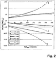
- Fig. 2 shows the relative change in clearance with a change in the dialysis fluid Q d by -200 ml / min, -100 ml / min (reduction) and + 300 ml / min (increase) from a given, original dialysis fluid Q d of 500 ml / min and a given blood flow rate Q b of 300 ml / min when operating the dialyzer 1 in countercurrent ⁇ ⁇ and when operating in cocurrent ⁇ for a Hemodialysis treatment (HD).
- the clearance K is plotted at the original dialysis fluid rate of 500 ml / min.
- the determined values of the clearance K are between 60 and 200 ml / min.
- a clearance K of at least 150 ml / min is also to be expected in cocurrent before changing the dialysis fluid Q b .
- the central control unit 13 and the arithmetic and evaluation unit 14 are configured such that the individual method steps of the method according to the invention for detecting the flow direction are performed.
- dialyzer 1 should be operated in countercurrent.
- the countercurrent operation is therefore the normal operation. This should be checked in the present embodiment.
- the measuring unit measures the diffusive clearance K diff, 1 .
- a concentrate bolus is generated by short-term change of the concentrate composition in the device 5 for providing fresh dialysis fluid in the dialysis fluid circuit I upstream of the dialyzer, which is measured with the sensors 17A and 17B of the measuring unit upstream and downstream of the dialyzer 1.
- the sensor 17A upstream of the dialystor 1 can also be omitted if the size of the bolus is known.
- the measuring unit calculates the clearance K diff, 1 from the measured values obtained.
- the calculation of the clearance from the measured values belongs to the prior art ( DE 39 38 662 A1 . DE 197 47 360 A1 ).
- the computing and evaluation unit 14 compares the measured clearance K diff, 1 with a predetermined limit, which is above 160 ml / min, preferably above 175 ml / min, particularly preferably above 185 ml / min. If the clearance K diff, 1 is above the limit value, the computing and evaluation unit 14 closes to operate in countercurrent, since such a high value for the clearance can not be achieved in DC operation, but this can be checked again below. Otherwise, a DC operation is concluded, which can also be checked again.
- a predetermined limit which is above 160 ml / min, preferably above 175 ml / min, particularly preferably above 185 ml / min.
- the dialysis fluid Q d is now changed by a predetermined amount, ie, the dialysis fluid Q d is increased or decreased, the blood flow rate Q b is maintained. After changing the dialysis fluid Q d , the clearance K diff, 2 is measured again with the measuring unit.
- the measured values K diff, 1 and K diff, 2 are stored in a memory (not shown) of the arithmetic and evaluation unit 14.
- the calculation and evaluation unit 14 calculates the amount of the difference between the expected value of the clearance ( K diff, 2 ) ⁇ ⁇ for the counterflow after the change of the dialysis fluid rate and the clearance measured before the change of the dialysis fluid rate by the amount of the expected change in the Determine clearance for the countercurrent, and calculate the amount of difference between the expected value of the clearance ( K diff, 2 ) ⁇ for the DC after the change in the dialysis fluid and the measured before the change in the dialysis fluid clearance by the amount of the expected change to determine the clearance for the direct current.
- the computing and evaluation unit 14 then calculates the amount of the difference between the measured change in the clearance and the expected value of the Change in clearance in the case of countercurrent and calculate the amount of difference between the measured change in clearance and the expected value of change in clearance in the case of direct current.
- the two difference values are then compared with each other. If the amount of the difference for the countercurrent is smaller than the amount of the difference for the direct current, the arithmetic and evaluation unit 14 closes to operate in countercurrent, which is the desired operation in the present embodiment. On the other hand, if the amount of the difference for the DC current is less than the amount of the difference for the countercurrent, DC operation is assumed, which in the present embodiment is not the desired operation, i. a faulty state would be.
- the arithmetic and evaluation unit 14 also generates a control signal indicating the operating state, which receives the display unit 18A, so that the countercurrent or DC operation is displayed.
- the arithmetic and evaluation unit 14 If the dialyzer 1 should not be properly connected to the dialysis fluid lines 6, 7, i. the connections should be reversed, the arithmetic and evaluation unit 14 generates a control signal which receives the alarm unit 18B. The alarm unit 18B then gives an alarm. In addition, the arithmetic and evaluation unit 14 generates a control signal which the central control unit 13 receives. Thereupon, the control unit 13 makes an intervention in the machine control. This intervention can be that the execution of the blood treatment is interrupted. Alternatively, it is possible to reverse the flow direction by operating the respective valves 16A-16D, so that the dialyzer is actually operated countercurrently.
Landscapes
- Health & Medical Sciences (AREA)
- Heart & Thoracic Surgery (AREA)
- Urology & Nephrology (AREA)
- Hematology (AREA)
- Animal Behavior & Ethology (AREA)
- Engineering & Computer Science (AREA)
- Anesthesiology (AREA)
- Biomedical Technology (AREA)
- Emergency Medicine (AREA)
- Life Sciences & Earth Sciences (AREA)
- Vascular Medicine (AREA)
- General Health & Medical Sciences (AREA)
- Public Health (AREA)
- Veterinary Medicine (AREA)
- Physics & Mathematics (AREA)
- Fluid Mechanics (AREA)
- External Artificial Organs (AREA)
Claims (9)
- Dispositif de détection du sens de l'écoulement de liquide à travers un dialyseur (1), qui présente une chambre de sang (4) traversée par le sang et une chambre de liquide de dialyse (3) traversée par le liquide de dialyse, qui sont séparées l'une de l'autre par une membrane semi-perméable (2), dans lequel le dispositif de détection du sens de l'écoulement de liquide présente une unité de mesure pour la mesure de la clairance ou d'une grandeur caractéristique de la clairance,
caractérisé en ce que
une unité de calcul et d'évaluation (13) est prévue, qui est configurée de sorte que la clairance mesurée ou une grandeur caractéristique de la clairance soit comparée avec une valeur limite prédéfinie, dans lequel il est conclu au sens de l'écoulement du sang à travers la chambre de sang et du liquide de dialyse à travers la chambre de liquide de dialyse à contre-courant, lorsque la clairance ou une grandeur caractéristique de la clairance est supérieure à la valeur limite prédéfinie. - Dispositif de détection du sens de l'écoulement de liquide à travers un dialyseur (1), qui présente une chambre de sang (4) traversée par le sang et une chambre de liquide de dialyse (3) traversée par le liquide de dialyse, qui sont séparées l'une de l'autre par une membrane semi-perméable (2), dans lequel le dispositif de détection du sens de l'écoulement de liquide présente :une unité de commande (14) pour la modification du débit du liquide de dialyse à travers la chambre de liquide de dialyse (3) du dialyseur (1) d'une valeur prédéfinie, etune unité de mesure (5 ; 14 ; 17A, 17B) pour la mesure de la clairance ou d'une grandeur caractéristique de la clairance avant et après la modification du débit de liquide de dialyse,caractérisé en ce queune unité de calcul et d'évaluation (14) est prévue, qui est configurée de sorte que sur la base de la modification de la clairance ou d'une grandeur caractéristique de la clairance, qui est imputable à une modification du débit de liquide de dialyse d'une valeur prédéfinie, il soit conclu au sens de l'écoulement du sang à travers la chambre de sang (4) et du liquide de dialyse à travers la chambre de liquide de dialyse (3) à contre-courant ou en co-courant.
- Dispositif selon la revendication 2, caractérisé en ce que
l'unité de calcul et d'évaluation (14) est configurée de sorte
que la valeur de la modification escomptée de la clairance à imputer à la modification du débit de liquide de dialyse ou de la grandeur caractéristique de la clairance sur la base d'un rapport décrivant la dépendance de la clairance ou de la grandeur caractéristique de la clairance du débit de liquide de dialyse soit calculée pour un écoulement du liquide de dialyse à contre-courant ou en co-courant,
que la valeur de la modification réelle de la clairance ou de la grandeur caractéristique de la clairance soit calculée à partir de la clairance mesurée avant et après la modification du débit de liquide de dialyse ou de la grandeur caractéristique de la clairance, et
qu'il soit conclu à un écoulement à contre-courant ou en co-courant sur la base d'une comparaison de la valeur de la modification réelle de la clairance ou de la grandeur caractéristique de la clairance avec la valeur escomptée de la modification de la clairance ou de la grandeur caractéristique de la clairance pour le contre-courant et le co-courant. - Dispositif selon la revendication 3, caractérisé en ce que
l'unité de calcul et d'évaluation (14) est configurée de sorte que
la valeur de la différence entre la valeur de la modification réelle de la clairance ou de la grandeur caractéristique de la clairance et la valeur escomptée de la modification de la clairance ou de la grandeur caractéristique de la clairance pour le contre-courant et
la valeur de la différence entre la valeur de la modification réelle de la clairance ou de la grandeur caractéristique de la clairance et la valeur escomptée de la modification de la clairance ou de la grandeur caractéristique de la clairance pour le co-courant soient calculées, dans lequel
il est conclu à un écoulement en co-courant, lorsque la valeur de la différence pour le co-courant est inférieure à la valeur de la différence pour le contre-courant, et
il est conclu à un écoulement à contre-courant, lorsque la valeur de la différence pour le contre-courant est inférieure à la valeur de la différence pour le co-courant. - Dispositif selon l'une quelconque des revendications 1 à 4, caractérisé en ce que l'unité de mesure (5 ; 14, 17A, 17B) pour la mesure de la clairance ou de la grandeur caractéristique de la clairance présente :des moyens (5) de modification d'une propriété physique et/ou chimique du liquide de dialyse s'écoulant dans la chambre de liquide de dialyse (3), etdes moyens (17B) de mesure de la propriété physique et/ou chimique du liquide de dialyse s'écoulant de la chambre de liquide de dialyse (3).
- Dispositif selon la revendication 5, caractérisé en ce que la propriété physique et/ou chimique est la concentration d'une substance dans le liquide de dialyse, dans lequel les moyens (17A, 17B) de mesure de la propriété physique et/ou chimique sont des moyens de mesure de la concentration de substance.
- Dispositif selon l'une quelconque des revendications 1 à 6, caractérisé en ce que l'unité de calcul et d'évaluation (14) est configurée de sorte que l'unité de calcul et d'évaluation (14) génère après la détermination du sens d'écoulement un signal signalant l'état de fonctionnement en contre-courant ou un signal signalant l'état de fonctionnement en co-courant.
- Dispositif selon la revendication 7, caractérisé en ce qu'une unité d'affichage (18B) est prévue pour l'affichage de l'état de fonctionnement.
- Dispositif de traitement sanguin extracorporel avec un circuit sanguin extracorporel (II), qui englobe la chambre de sang (4) d'un dialyseur (1) subdivisé par une membrane semi-perméable (2) en la chambre de sang (4) et une chambre de liquide de dialyse (3), et un système de liquide de dialyse (I), qui englobe la chambre de liquide de dialyse (3), caractérisé en ce que le dispositif de traitement sanguin extracorporel présente un dispositif de détection du sens de l'écoulement de liquide selon l'une quelconque des revendications 1 à 8.
Applications Claiming Priority (2)
| Application Number | Priority Date | Filing Date | Title |
|---|---|---|---|
| DE102014011250.0A DE102014011250A1 (de) | 2014-08-01 | 2014-08-01 | Vorrichtung zur Erkennung der Richtung der Flüssigkeitsströmung durch einen Dialysator |
| PCT/EP2015/066577 WO2016016039A1 (fr) | 2014-08-01 | 2015-07-20 | Dispositif de détection du sens de l'écoulement du liquide à travers un dialyseur |
Publications (2)
| Publication Number | Publication Date |
|---|---|
| EP3174571A1 EP3174571A1 (fr) | 2017-06-07 |
| EP3174571B1 true EP3174571B1 (fr) | 2019-08-28 |
Family
ID=53682716
Family Applications (1)
| Application Number | Title | Priority Date | Filing Date |
|---|---|---|---|
| EP15739286.1A Active EP3174571B1 (fr) | 2014-08-01 | 2015-07-20 | Dispositif de détection du sens de l'écoulement du liquide à travers un dialyseur |
Country Status (7)
| Country | Link |
|---|---|
| US (1) | US10639411B2 (fr) |
| EP (1) | EP3174571B1 (fr) |
| JP (1) | JP6573967B2 (fr) |
| CN (1) | CN106659830B (fr) |
| CA (1) | CA2956484C (fr) |
| DE (1) | DE102014011250A1 (fr) |
| WO (1) | WO2016016039A1 (fr) |
Cited By (1)
| Publication number | Priority date | Publication date | Assignee | Title |
|---|---|---|---|---|
| EP4699627A1 (fr) | 2024-08-20 | 2026-02-25 | B. Braun Avitum AG | Machine de traitement extracorporel du sang et procédé de primer automatique d'un dialyseur |
Families Citing this family (8)
| Publication number | Priority date | Publication date | Assignee | Title |
|---|---|---|---|---|
| DE102014011250A1 (de) * | 2014-08-01 | 2016-02-04 | Fresenius Medical Care Deutschland Gmbh | Vorrichtung zur Erkennung der Richtung der Flüssigkeitsströmung durch einen Dialysator |
| WO2018001996A1 (fr) * | 2016-06-30 | 2018-01-04 | Gambro Lundia Ab | Test de connexion pour machines de traitement du sang ii |
| WO2018001994A1 (fr) * | 2016-06-30 | 2018-01-04 | Gambro Lundia Ab | Test de connexion pour machines de traitement du sang i |
| US11992589B2 (en) * | 2016-10-03 | 2024-05-28 | Gambro Lundia Ab | Measuring access flow rate by use of blood treatment machine |
| DE102017005535A1 (de) * | 2017-06-10 | 2018-12-13 | Fresenius Medical Care Deutschland Gmbh | Vorrichtung zur extrakorporalen Blutbehandlung und Vorrichtung zum Sammeln von Blutgerinnseln sowie Verfahren zum Bestimmen eines hämodynamischen Parameters während einer extrakorporalen Blutbehandlung |
| JP6997582B2 (ja) * | 2017-10-17 | 2022-01-17 | 日機装株式会社 | 血液浄化装置 |
| JP6914803B2 (ja) * | 2017-10-17 | 2021-08-04 | 日機装株式会社 | 血液浄化装置 |
| US12415025B2 (en) | 2018-04-19 | 2025-09-16 | Nephratech Llc | Physiologic cardiovascular pH balanced counter current electrolyte transfer and fluid removal system |
Family Cites Families (7)
| Publication number | Priority date | Publication date | Assignee | Title |
|---|---|---|---|---|
| DE3938662A1 (de) | 1989-11-21 | 1991-07-18 | Fresenius Ag | Verfahren zur in-vivo-bestimmung von parametern der haemodialyse |
| DE19747360B8 (de) | 1997-10-27 | 2007-05-16 | Fresenius Medical Care De Gmbh | Verfahren zur Messung von Leistungsparametern von Stoff- und Energieaustausch Modulen |
| SE0200370D0 (sv) * | 2002-02-08 | 2002-02-08 | Gambro Lundia Ab | Method and apparatus for determining access flow |
| US20100168925A1 (en) * | 2006-06-08 | 2010-07-01 | Peter Hilgers | Device and method for controlling an extracorporeal blood- treating apparatus |
| DE102010032980A1 (de) * | 2010-07-31 | 2012-02-02 | Fresenius Medical Care Deutschland Gmbh | Vorrichtung und Verfahren zur Erkennung der Richtung der Flüssigkeitsströmung durch einen Dialysator |
| DE102011102962A1 (de) * | 2011-05-23 | 2012-11-29 | Fresenius Medical Care Deutschland Gmbh | Vorrichtung und Verfahren zur Erkennung eines Betriebszustandes einer extrakorporalen Blutbehandlung |
| DE102014011250A1 (de) * | 2014-08-01 | 2016-02-04 | Fresenius Medical Care Deutschland Gmbh | Vorrichtung zur Erkennung der Richtung der Flüssigkeitsströmung durch einen Dialysator |
-
2014
- 2014-08-01 DE DE102014011250.0A patent/DE102014011250A1/de not_active Ceased
-
2015
- 2015-07-20 JP JP2017505523A patent/JP6573967B2/ja active Active
- 2015-07-20 EP EP15739286.1A patent/EP3174571B1/fr active Active
- 2015-07-20 CN CN201580040666.2A patent/CN106659830B/zh active Active
- 2015-07-20 US US15/328,691 patent/US10639411B2/en active Active
- 2015-07-20 WO PCT/EP2015/066577 patent/WO2016016039A1/fr not_active Ceased
- 2015-07-20 CA CA2956484A patent/CA2956484C/fr active Active
Non-Patent Citations (1)
| Title |
|---|
| None * |
Cited By (2)
| Publication number | Priority date | Publication date | Assignee | Title |
|---|---|---|---|---|
| EP4699627A1 (fr) | 2024-08-20 | 2026-02-25 | B. Braun Avitum AG | Machine de traitement extracorporel du sang et procédé de primer automatique d'un dialyseur |
| DE102024123677A1 (de) | 2024-08-20 | 2026-02-26 | B.Braun Avitum Ag | Extrakorporale Blutbehandlungsmaschine und Verfahren zum automatischen Primen eines Dialysators |
Also Published As
| Publication number | Publication date |
|---|---|
| JP2017522141A (ja) | 2017-08-10 |
| CA2956484C (fr) | 2022-11-29 |
| DE102014011250A1 (de) | 2016-02-04 |
| CN106659830A (zh) | 2017-05-10 |
| JP6573967B2 (ja) | 2019-09-11 |
| CN106659830B (zh) | 2019-12-17 |
| WO2016016039A1 (fr) | 2016-02-04 |
| EP3174571A1 (fr) | 2017-06-07 |
| CA2956484A1 (fr) | 2016-02-04 |
| US10639411B2 (en) | 2020-05-05 |
| US20170209634A1 (en) | 2017-07-27 |
Similar Documents
| Publication | Publication Date | Title |
|---|---|---|
| EP2217303B1 (fr) | Dispositif pour déterminer la recirculation dans une fistule ou la recirculation cardiopulmonaire, et dispositif de traitement du sang pourvu d'un dispositif pour déterminer la circulation en fistule ou la part de recirculation cardiopulmonaire | |
| EP3174571A1 (fr) | Dispositif de détection du sens de l'écoulement du liquide à travers un dialyseur | |
| EP2627368B1 (fr) | Procédé et dispositif pour mesurer et éliminer des variations du système dans un dispositif de traitement du sang | |
| EP2714128B1 (fr) | Dispositif et procédé pour la détection d'un état de fonctionnement d'un traitement de sang extracorporel | |
| DE102005001051B4 (de) | Vorrichtung und Verfahren zur Erkennung von Komplikationen während einer extrakorporalen Blutbehandlung | |
| EP2150292B1 (fr) | Dispositif de contrôle d'une unité de traitement du sang d'un dispositif de traitement du sang extracorporel | |
| EP3183013B1 (fr) | Machine de dialyse ayant la capacité de déterminer une propriété pré-dialytique dans le sang d'un patient sous dialyse | |
| DE10328435B3 (de) | Vorrichtung zur extrakorporalen Blutbehandlung mit einer Einrichtung zur Überprüfung eines Sterilfilters und Verfahren zum Überprüfen eines Sterilfilters einer extrakorporalen Blutbehandlungsvorrichtung | |
| DE102014011699B4 (de) | Vorrichtung zur Ermittlung eines optimalen Dialysatflusses für eine extrakorporale Blutbehandlung mit einer extrakorporalen Blutbehandlungsvorrichtung | |
| EP2040775B1 (fr) | Procédé et dispositif de prédétermination de paramètres de traitement pour un traitement par dialyse extracorporelle | |
| WO2011128098A2 (fr) | Dispositif et procédé pour contrôler le raccordement d'une unité de traitement du sang au système de liquide d'un dispositif de traitement extracorporel du sang | |
| DE10317024A1 (de) | Blutbehandlungsvorrichtung | |
| EP2598186B1 (fr) | Dispositif et procédé d'identification du sens de l'écoulement d'un liquide à travers un dialyseur | |
| EP2432518B1 (fr) | Dispositif et procédé pour reconnaître un système de conduite flexible pour un dispositif de traitement extracorporel du sang | |
| EP3493861B1 (fr) | Procédé pour surveiller la teneur en bicarbonate et la teneur en sodium d'un dialysat | |
| DE102014015795A1 (de) | System umfassend mehrere medizinische Geräte, vorzugsweise Dialysegeräte und Verfahren zu dessen Betrieb | |
| EP2783714B1 (fr) | Procédé et dispositif de détermination d'un état de recirculation | |
| DE102017000495A1 (de) | DlALYSATKONZENTRATlON-MESSSENSORDlAGNOSE | |
| WO2023062047A1 (fr) | Dispositif de surveillance d'une épuration du sang au moyen d'un dispositif d'épuration du sang extracorporel | |
| EP4142822B1 (fr) | Dispositif de dialyse avec un dispositif pour déterminer au moins deux paramètres de l'hémodialyse |
Legal Events
| Date | Code | Title | Description |
|---|---|---|---|
| STAA | Information on the status of an ep patent application or granted ep patent |
Free format text: STATUS: THE INTERNATIONAL PUBLICATION HAS BEEN MADE |
|
| 17P | Request for examination filed |
Effective date: 20170220 |
|
| AK | Designated contracting states |
Kind code of ref document: A1 Designated state(s): AL AT BE BG CH CY CZ DE DK EE ES FI FR GB GR HR HU IE IS IT LI LT LU LV MC MK MT NL NO PL PT RO RS SE SI SK SM TR |
|
| AX | Request for extension of the european patent |
Extension state: BA ME |
|
| PUAI | Public reference made under article 153(3) epc to a published international application that has entered the european phase |
Free format text: ORIGINAL CODE: 0009012 |
|
| STAA | Information on the status of an ep patent application or granted ep patent |
Free format text: STATUS: REQUEST FOR EXAMINATION WAS MADE |
|
| DAV | Request for validation of the european patent (deleted) | ||
| DAX | Request for extension of the european patent (deleted) | ||
| STAA | Information on the status of an ep patent application or granted ep patent |
Free format text: STATUS: EXAMINATION IS IN PROGRESS |
|
| 17Q | First examination report despatched |
Effective date: 20180724 |
|
| GRAP | Despatch of communication of intention to grant a patent |
Free format text: ORIGINAL CODE: EPIDOSNIGR1 |
|
| STAA | Information on the status of an ep patent application or granted ep patent |
Free format text: STATUS: GRANT OF PATENT IS INTENDED |
|
| INTG | Intention to grant announced |
Effective date: 20190225 |
|
| GRAS | Grant fee paid |
Free format text: ORIGINAL CODE: EPIDOSNIGR3 |
|
| GRAA | (expected) grant |
Free format text: ORIGINAL CODE: 0009210 |
|
| STAA | Information on the status of an ep patent application or granted ep patent |
Free format text: STATUS: THE PATENT HAS BEEN GRANTED |
|
| AK | Designated contracting states |
Kind code of ref document: B1 Designated state(s): AL AT BE BG CH CY CZ DE DK EE ES FI FR GB GR HR HU IE IS IT LI LT LU LV MC MK MT NL NO PL PT RO RS SE SI SK SM TR |
|
| REG | Reference to a national code |
Ref country code: GB Ref legal event code: FG4D Free format text: NOT ENGLISH |
|
| REG | Reference to a national code |
Ref country code: CH Ref legal event code: EP |
|
| REG | Reference to a national code |
Ref country code: DE Ref legal event code: R096 Ref document number: 502015010168 Country of ref document: DE |
|
| REG | Reference to a national code |
Ref country code: AT Ref legal event code: REF Ref document number: 1171571 Country of ref document: AT Kind code of ref document: T Effective date: 20190915 |
|
| REG | Reference to a national code |
Ref country code: IE Ref legal event code: FG4D Free format text: LANGUAGE OF EP DOCUMENT: GERMAN |
|
| REG | Reference to a national code |
Ref country code: SE Ref legal event code: TRGR |
|
| REG | Reference to a national code |
Ref country code: NL Ref legal event code: MP Effective date: 20190828 |
|
| REG | Reference to a national code |
Ref country code: LT Ref legal event code: MG4D |
|
| PG25 | Lapsed in a contracting state [announced via postgrant information from national office to epo] |
Ref country code: HR Free format text: LAPSE BECAUSE OF FAILURE TO SUBMIT A TRANSLATION OF THE DESCRIPTION OR TO PAY THE FEE WITHIN THE PRESCRIBED TIME-LIMIT Effective date: 20190828 Ref country code: LT Free format text: LAPSE BECAUSE OF FAILURE TO SUBMIT A TRANSLATION OF THE DESCRIPTION OR TO PAY THE FEE WITHIN THE PRESCRIBED TIME-LIMIT Effective date: 20190828 Ref country code: BG Free format text: LAPSE BECAUSE OF FAILURE TO SUBMIT A TRANSLATION OF THE DESCRIPTION OR TO PAY THE FEE WITHIN THE PRESCRIBED TIME-LIMIT Effective date: 20191128 Ref country code: NL Free format text: LAPSE BECAUSE OF FAILURE TO SUBMIT A TRANSLATION OF THE DESCRIPTION OR TO PAY THE FEE WITHIN THE PRESCRIBED TIME-LIMIT Effective date: 20190828 Ref country code: FI Free format text: LAPSE BECAUSE OF FAILURE TO SUBMIT A TRANSLATION OF THE DESCRIPTION OR TO PAY THE FEE WITHIN THE PRESCRIBED TIME-LIMIT Effective date: 20190828 Ref country code: PT Free format text: LAPSE BECAUSE OF FAILURE TO SUBMIT A TRANSLATION OF THE DESCRIPTION OR TO PAY THE FEE WITHIN THE PRESCRIBED TIME-LIMIT Effective date: 20191230 Ref country code: NO Free format text: LAPSE BECAUSE OF FAILURE TO SUBMIT A TRANSLATION OF THE DESCRIPTION OR TO PAY THE FEE WITHIN THE PRESCRIBED TIME-LIMIT Effective date: 20191128 |
|
| PG25 | Lapsed in a contracting state [announced via postgrant information from national office to epo] |
Ref country code: RS Free format text: LAPSE BECAUSE OF FAILURE TO SUBMIT A TRANSLATION OF THE DESCRIPTION OR TO PAY THE FEE WITHIN THE PRESCRIBED TIME-LIMIT Effective date: 20190828 Ref country code: IS Free format text: LAPSE BECAUSE OF FAILURE TO SUBMIT A TRANSLATION OF THE DESCRIPTION OR TO PAY THE FEE WITHIN THE PRESCRIBED TIME-LIMIT Effective date: 20191228 Ref country code: LV Free format text: LAPSE BECAUSE OF FAILURE TO SUBMIT A TRANSLATION OF THE DESCRIPTION OR TO PAY THE FEE WITHIN THE PRESCRIBED TIME-LIMIT Effective date: 20190828 Ref country code: AL Free format text: LAPSE BECAUSE OF FAILURE TO SUBMIT A TRANSLATION OF THE DESCRIPTION OR TO PAY THE FEE WITHIN THE PRESCRIBED TIME-LIMIT Effective date: 20190828 Ref country code: GR Free format text: LAPSE BECAUSE OF FAILURE TO SUBMIT A TRANSLATION OF THE DESCRIPTION OR TO PAY THE FEE WITHIN THE PRESCRIBED TIME-LIMIT Effective date: 20191129 |
|
| PG25 | Lapsed in a contracting state [announced via postgrant information from national office to epo] |
Ref country code: TR Free format text: LAPSE BECAUSE OF FAILURE TO SUBMIT A TRANSLATION OF THE DESCRIPTION OR TO PAY THE FEE WITHIN THE PRESCRIBED TIME-LIMIT Effective date: 20190828 |
|
| PG25 | Lapsed in a contracting state [announced via postgrant information from national office to epo] |
Ref country code: DK Free format text: LAPSE BECAUSE OF FAILURE TO SUBMIT A TRANSLATION OF THE DESCRIPTION OR TO PAY THE FEE WITHIN THE PRESCRIBED TIME-LIMIT Effective date: 20190828 Ref country code: PL Free format text: LAPSE BECAUSE OF FAILURE TO SUBMIT A TRANSLATION OF THE DESCRIPTION OR TO PAY THE FEE WITHIN THE PRESCRIBED TIME-LIMIT Effective date: 20190828 Ref country code: EE Free format text: LAPSE BECAUSE OF FAILURE TO SUBMIT A TRANSLATION OF THE DESCRIPTION OR TO PAY THE FEE WITHIN THE PRESCRIBED TIME-LIMIT Effective date: 20190828 Ref country code: RO Free format text: LAPSE BECAUSE OF FAILURE TO SUBMIT A TRANSLATION OF THE DESCRIPTION OR TO PAY THE FEE WITHIN THE PRESCRIBED TIME-LIMIT Effective date: 20190828 |
|
| PG25 | Lapsed in a contracting state [announced via postgrant information from national office to epo] |
Ref country code: SM Free format text: LAPSE BECAUSE OF FAILURE TO SUBMIT A TRANSLATION OF THE DESCRIPTION OR TO PAY THE FEE WITHIN THE PRESCRIBED TIME-LIMIT Effective date: 20190828 Ref country code: CZ Free format text: LAPSE BECAUSE OF FAILURE TO SUBMIT A TRANSLATION OF THE DESCRIPTION OR TO PAY THE FEE WITHIN THE PRESCRIBED TIME-LIMIT Effective date: 20190828 Ref country code: SK Free format text: LAPSE BECAUSE OF FAILURE TO SUBMIT A TRANSLATION OF THE DESCRIPTION OR TO PAY THE FEE WITHIN THE PRESCRIBED TIME-LIMIT Effective date: 20190828 Ref country code: IS Free format text: LAPSE BECAUSE OF FAILURE TO SUBMIT A TRANSLATION OF THE DESCRIPTION OR TO PAY THE FEE WITHIN THE PRESCRIBED TIME-LIMIT Effective date: 20200224 |
|
| REG | Reference to a national code |
Ref country code: DE Ref legal event code: R097 Ref document number: 502015010168 Country of ref document: DE |
|
| PLBE | No opposition filed within time limit |
Free format text: ORIGINAL CODE: 0009261 |
|
| STAA | Information on the status of an ep patent application or granted ep patent |
Free format text: STATUS: NO OPPOSITION FILED WITHIN TIME LIMIT |
|
| PG2D | Information on lapse in contracting state deleted |
Ref country code: IS |
|
| 26N | No opposition filed |
Effective date: 20200603 |
|
| PG25 | Lapsed in a contracting state [announced via postgrant information from national office to epo] |
Ref country code: SI Free format text: LAPSE BECAUSE OF FAILURE TO SUBMIT A TRANSLATION OF THE DESCRIPTION OR TO PAY THE FEE WITHIN THE PRESCRIBED TIME-LIMIT Effective date: 20190828 |
|
| PG25 | Lapsed in a contracting state [announced via postgrant information from national office to epo] |
Ref country code: ES Free format text: LAPSE BECAUSE OF FAILURE TO SUBMIT A TRANSLATION OF THE DESCRIPTION OR TO PAY THE FEE WITHIN THE PRESCRIBED TIME-LIMIT Effective date: 20190828 |
|
| PG25 | Lapsed in a contracting state [announced via postgrant information from national office to epo] |
Ref country code: MC Free format text: LAPSE BECAUSE OF FAILURE TO SUBMIT A TRANSLATION OF THE DESCRIPTION OR TO PAY THE FEE WITHIN THE PRESCRIBED TIME-LIMIT Effective date: 20190828 |
|
| REG | Reference to a national code |
Ref country code: CH Ref legal event code: PL |
|
| REG | Reference to a national code |
Ref country code: BE Ref legal event code: MM Effective date: 20200731 |
|
| PG25 | Lapsed in a contracting state [announced via postgrant information from national office to epo] |
Ref country code: LI Free format text: LAPSE BECAUSE OF NON-PAYMENT OF DUE FEES Effective date: 20200731 Ref country code: LU Free format text: LAPSE BECAUSE OF NON-PAYMENT OF DUE FEES Effective date: 20200720 Ref country code: CH Free format text: LAPSE BECAUSE OF NON-PAYMENT OF DUE FEES Effective date: 20200731 |
|
| PG25 | Lapsed in a contracting state [announced via postgrant information from national office to epo] |
Ref country code: BE Free format text: LAPSE BECAUSE OF NON-PAYMENT OF DUE FEES Effective date: 20200731 |
|
| PG25 | Lapsed in a contracting state [announced via postgrant information from national office to epo] |
Ref country code: IE Free format text: LAPSE BECAUSE OF NON-PAYMENT OF DUE FEES Effective date: 20200720 |
|
| REG | Reference to a national code |
Ref country code: AT Ref legal event code: MM01 Ref document number: 1171571 Country of ref document: AT Kind code of ref document: T Effective date: 20200720 |
|
| PG25 | Lapsed in a contracting state [announced via postgrant information from national office to epo] |
Ref country code: AT Free format text: LAPSE BECAUSE OF NON-PAYMENT OF DUE FEES Effective date: 20200720 |
|
| PG25 | Lapsed in a contracting state [announced via postgrant information from national office to epo] |
Ref country code: MT Free format text: LAPSE BECAUSE OF FAILURE TO SUBMIT A TRANSLATION OF THE DESCRIPTION OR TO PAY THE FEE WITHIN THE PRESCRIBED TIME-LIMIT Effective date: 20190828 Ref country code: CY Free format text: LAPSE BECAUSE OF FAILURE TO SUBMIT A TRANSLATION OF THE DESCRIPTION OR TO PAY THE FEE WITHIN THE PRESCRIBED TIME-LIMIT Effective date: 20190828 |
|
| PG25 | Lapsed in a contracting state [announced via postgrant information from national office to epo] |
Ref country code: MK Free format text: LAPSE BECAUSE OF FAILURE TO SUBMIT A TRANSLATION OF THE DESCRIPTION OR TO PAY THE FEE WITHIN THE PRESCRIBED TIME-LIMIT Effective date: 20190828 |
|
| P01 | Opt-out of the competence of the unified patent court (upc) registered |
Effective date: 20230602 |
|
| PGFP | Annual fee paid to national office [announced via postgrant information from national office to epo] |
Ref country code: GB Payment date: 20250619 Year of fee payment: 11 |
|
| PGFP | Annual fee paid to national office [announced via postgrant information from national office to epo] |
Ref country code: FR Payment date: 20250620 Year of fee payment: 11 |
|
| PGFP | Annual fee paid to national office [announced via postgrant information from national office to epo] |
Ref country code: SE Payment date: 20250619 Year of fee payment: 11 |
|
| PGFP | Annual fee paid to national office [announced via postgrant information from national office to epo] |
Ref country code: DE Payment date: 20250620 Year of fee payment: 11 |
|
| PGFP | Annual fee paid to national office [announced via postgrant information from national office to epo] |
Ref country code: IT Payment date: 20250619 Year of fee payment: 11 |