EP3174689B1 - Composant micromécanique et procédé de fabrication - Google Patents
Composant micromécanique et procédé de fabrication Download PDFInfo
- Publication number
- EP3174689B1 EP3174689B1 EP15745164.2A EP15745164A EP3174689B1 EP 3174689 B1 EP3174689 B1 EP 3174689B1 EP 15745164 A EP15745164 A EP 15745164A EP 3174689 B1 EP3174689 B1 EP 3174689B1
- Authority
- EP
- European Patent Office
- Prior art keywords
- starting material
- cavity
- component
- liquid starting
- micromechanical
- Prior art date
- Legal status (The legal status is an assumption and is not a legal conclusion. Google has not performed a legal analysis and makes no representation as to the accuracy of the status listed.)
- Active
Links
Images

Classifications
-
- B—PERFORMING OPERATIONS; TRANSPORTING
- B81—MICROSTRUCTURAL TECHNOLOGY
- B81C—PROCESSES OR APPARATUS SPECIALLY ADAPTED FOR THE MANUFACTURE OR TREATMENT OF MICROSTRUCTURAL DEVICES OR SYSTEMS
- B81C1/00—Manufacture or treatment of devices or systems in or on a substrate
- B81C1/00349—Creating layers of material on a substrate
- B81C1/00373—Selective deposition, e.g. printing or microcontact printing
-
- B—PERFORMING OPERATIONS; TRANSPORTING
- B29—WORKING OF PLASTICS; WORKING OF SUBSTANCES IN A PLASTIC STATE IN GENERAL
- B29C—SHAPING OR JOINING OF PLASTICS; SHAPING OF MATERIAL IN A PLASTIC STATE, NOT OTHERWISE PROVIDED FOR; AFTER-TREATMENT OF THE SHAPED PRODUCTS, e.g. REPAIRING
- B29C64/00—Additive manufacturing, i.e. manufacturing of three-dimensional [3D] objects by additive deposition, additive agglomeration or additive layering, e.g. by 3D printing, stereolithography or selective laser sintering
- B29C64/10—Processes of additive manufacturing
- B29C64/106—Processes of additive manufacturing using only liquids or viscous materials, e.g. depositing a continuous bead of viscous material
- B29C64/124—Processes of additive manufacturing using only liquids or viscous materials, e.g. depositing a continuous bead of viscous material using layers of liquid which are selectively solidified
- B29C64/129—Processes of additive manufacturing using only liquids or viscous materials, e.g. depositing a continuous bead of viscous material using layers of liquid which are selectively solidified characterised by the energy source therefor, e.g. by global irradiation combined with a mask
- B29C64/135—Processes of additive manufacturing using only liquids or viscous materials, e.g. depositing a continuous bead of viscous material using layers of liquid which are selectively solidified characterised by the energy source therefor, e.g. by global irradiation combined with a mask the energy source being concentrated, e.g. scanning lasers or focused light sources
-
- B—PERFORMING OPERATIONS; TRANSPORTING
- B33—ADDITIVE MANUFACTURING TECHNOLOGY
- B33Y—ADDITIVE MANUFACTURING, i.e. MANUFACTURING OF THREE-DIMENSIONAL [3D] OBJECTS BY ADDITIVE DEPOSITION, ADDITIVE AGGLOMERATION OR ADDITIVE LAYERING, e.g. BY 3D PRINTING, STEREOLITHOGRAPHY OR SELECTIVE LASER SINTERING
- B33Y10/00—Processes of additive manufacturing
-
- B—PERFORMING OPERATIONS; TRANSPORTING
- B33—ADDITIVE MANUFACTURING TECHNOLOGY
- B33Y—ADDITIVE MANUFACTURING, i.e. MANUFACTURING OF THREE-DIMENSIONAL [3D] OBJECTS BY ADDITIVE DEPOSITION, ADDITIVE AGGLOMERATION OR ADDITIVE LAYERING, e.g. BY 3D PRINTING, STEREOLITHOGRAPHY OR SELECTIVE LASER SINTERING
- B33Y80/00—Products made by additive manufacturing
-
- B—PERFORMING OPERATIONS; TRANSPORTING
- B81—MICROSTRUCTURAL TECHNOLOGY
- B81B—MICROSTRUCTURAL DEVICES OR SYSTEMS, e.g. MICROMECHANICAL DEVICES
- B81B7/00—Microstructural systems ; Auxiliary parts of microstructural devices or systems
- B81B7/0032—Packages or encapsulation
- B81B7/0074—3D packaging, i.e. encapsulation containing one or several MEMS devices arranged in planes non-parallel to the mounting board
-
- B—PERFORMING OPERATIONS; TRANSPORTING
- B81—MICROSTRUCTURAL TECHNOLOGY
- B81C—PROCESSES OR APPARATUS SPECIALLY ADAPTED FOR THE MANUFACTURE OR TREATMENT OF MICROSTRUCTURAL DEVICES OR SYSTEMS
- B81C3/00—Assembling of devices or systems from individually processed components
- B81C3/001—Bonding of two components
-
- B—PERFORMING OPERATIONS; TRANSPORTING
- B81—MICROSTRUCTURAL TECHNOLOGY
- B81C—PROCESSES OR APPARATUS SPECIALLY ADAPTED FOR THE MANUFACTURE OR TREATMENT OF MICROSTRUCTURAL DEVICES OR SYSTEMS
- B81C99/00—Subject matter not provided for in other groups of this subclass
- B81C99/0075—Manufacture of substrate-free structures
- B81C99/0095—Aspects relating to the manufacture of substrate-free structures, not covered by groups B81C99/008 - B81C99/009
-
- B—PERFORMING OPERATIONS; TRANSPORTING
- B81—MICROSTRUCTURAL TECHNOLOGY
- B81B—MICROSTRUCTURAL DEVICES OR SYSTEMS, e.g. MICROMECHANICAL DEVICES
- B81B2201/00—Specific applications of microelectromechanical systems
- B81B2201/03—Microengines and actuators
- B81B2201/038—Microengines and actuators not provided for in B81B2201/031 - B81B2201/037
-
- B—PERFORMING OPERATIONS; TRANSPORTING
- B81—MICROSTRUCTURAL TECHNOLOGY
- B81B—MICROSTRUCTURAL DEVICES OR SYSTEMS, e.g. MICROMECHANICAL DEVICES
- B81B2201/00—Specific applications of microelectromechanical systems
- B81B2201/04—Optical MEMS
- B81B2201/047—Optical MEMS not provided for in B81B2201/042 - B81B2201/045
-
- B—PERFORMING OPERATIONS; TRANSPORTING
- B81—MICROSTRUCTURAL TECHNOLOGY
- B81B—MICROSTRUCTURAL DEVICES OR SYSTEMS, e.g. MICROMECHANICAL DEVICES
- B81B2203/00—Basic microelectromechanical structures
- B81B2203/03—Static structures
- B81B2203/0315—Cavities
-
- B—PERFORMING OPERATIONS; TRANSPORTING
- B81—MICROSTRUCTURAL TECHNOLOGY
- B81B—MICROSTRUCTURAL DEVICES OR SYSTEMS, e.g. MICROMECHANICAL DEVICES
- B81B2203/00—Basic microelectromechanical structures
- B81B2203/03—Static structures
- B81B2203/0369—Static structures characterized by their profile
- B81B2203/0392—Static structures characterized by their profile profiles not provided for in B81B2203/0376 - B81B2203/0384
-
- B—PERFORMING OPERATIONS; TRANSPORTING
- B81—MICROSTRUCTURAL TECHNOLOGY
- B81C—PROCESSES OR APPARATUS SPECIALLY ADAPTED FOR THE MANUFACTURE OR TREATMENT OF MICROSTRUCTURAL DEVICES OR SYSTEMS
- B81C2201/00—Manufacture or treatment of microstructural devices or systems
- B81C2201/01—Manufacture or treatment of microstructural devices or systems in or on a substrate
- B81C2201/0174—Manufacture or treatment of microstructural devices or systems in or on a substrate for making multi-layered devices, film deposition or growing
- B81C2201/0183—Selective deposition
- B81C2201/0188—Selective deposition techniques not provided for in B81C2201/0184 - B81C2201/0187
-
- B—PERFORMING OPERATIONS; TRANSPORTING
- B81—MICROSTRUCTURAL TECHNOLOGY
- B81C—PROCESSES OR APPARATUS SPECIALLY ADAPTED FOR THE MANUFACTURE OR TREATMENT OF MICROSTRUCTURAL DEVICES OR SYSTEMS
- B81C2203/00—Forming microstructural systems
- B81C2203/03—Bonding two components
- B81C2203/038—Bonding techniques not provided for in B81C2203/031 - B81C2203/037
Definitions
- the invention relates to a method for producing micromechanical components, in which a liquid starting material which can be hardened by irradiation is applied to a substrate, the starting material is hardened in a partial volume by local irradiation with a first irradiation source in order to produce at least one three-dimensional structure and the remaining liquid starting material is at least partially removed.
- the application also relates to a micromechanical component which contains a liquid starting material which has been partially cured by irradiation.
- a method for producing three-dimensional microstructures is known.
- a liquid material is hardened by exposure to a focused laser beam. After the exposure is complete, the remaining liquid material can be removed so that the desired micromechanical component remains on the substrate.
- the invention is based on the object of specifying micromechanical components and a method for their production in which the micromechanical components can be easily reworked can take place and / or which can provide micromechanical components with movable individual parts.
- the starting material can be a photoresist known per se, which polymerizes on irradiation.
- the photoresist can contain a polymer, for example polymethyl methacrylate and / or polymethyl glutarimide.
- the starting material can contain at least one epoxy resin.
- the starting material can contain solvents, for example cyclopentanone or ⁇ -butyrolactron.
- the starting material can be applied to a substrate at least during the production of the micromechanical component.
- the substrate can be a glass or a semiconductor, for example a silicon wafer.
- the substrate can contain or consist of sapphire.
- the micromechanical component can remain on the substrate after its production, for example in order to monolithically integrate the micromechanical component together with micro-optical and / or microelectronic components.
- the micromechanical component can be removed from the substrate after its production and further processed separately.
- electromagnetic radiation can be used to harden the starting material be used. Due to its high brilliance, laser radiation from a first light source can advantageously be used to cure the starting material.
- the starting material can be hardened by a particle beam, for example an electron beam or a heavy ion beam.
- laser radiation can have a wavelength of approximately 2 ⁇ m to approximately 0.2 ⁇ m. In other embodiments of the invention, the laser radiation can have a wavelength of approximately 2 ⁇ m to approximately 1 ⁇ m.
- the hardening can be stimulated by multiphoton processes, so that the hardened spatial area can be limited to the focal point with maximum intensity. In this way, by changing the focus position, the depth to which the starting material hardens can also be influenced. Together with a translational movement of the light beam, a three-dimensional structure can be written into the starting material in this way.
- the remaining liquid starting material can be at least partially removed.
- the three-dimensional structure delimits at least one cavity in which the liquid starting material is enclosed.
- the liquid starting material within the cavity can be used as hydraulic fluid in order to generate micromechanical hydraulic components.
- the micromechanical component can be, for example, a hydraulic actuator and / or sensor or contain one.
- a micromechanical component which includes a comparatively thin-walled cavity
- a micromechanical component that includes a comparatively thin-walled cavity can be subsequently deformed so that a mechanical stress is formed in the wall.
- a micromechanical component that includes a comparatively thin-walled cavity can be subsequently deformed so that the wall at least partially adapts to the shape of an adjacent micro- or macromechanical component. If permanent mobility is not desired or required, the liquid starting material in the interior of the cavity can be subsequently hardened or polymerized, so that the micromechanical component only contains liquid starting material in the cavity during its production.
- the cavity can contain at least one reinforcement element.
- the reinforcement element can be provided to prevent or limit a deformation of the micromechanical component or a deformation of at least a partial area of a boundary wall of the cavity. In this way, mechanically more stable structures can be created.
- the reinforcement element can also be written into the liquid starting material by point-to-point exposure with a focused light beam from a first light source.
- the liquid starting material can be converted into the gas phase in a subsequent process step.
- the cavity can not only be filled with liquid starting material, but also, additionally or alternatively, with a gas.
- the cavity can have greater elasticity and / or changed damping.
- the gas can be used as hydraulic fluid, to drive a micromechanical actuator and / or to implement a micromechanical sensor.
- the conversion into the gas phase can take place by means of laser radiation, which dissociates the molecules of the originally liquid starting material and thus decomposes the starting material.
- the cavity can be delimited by a thin membrane which is opened and / or pierced in a subsequent method step.
- the starting material can at least partially emerge from the cavity.
- the liquid starting material can be hardened in a subsequent method step by irradiation with a second radiation source.
- the second radiation source can be selected from a superluminescent diode, a defocused laser beam, an arc lamp, a gas discharge lamp, natural sunlight or other radiation sources not mentioned here.
- the second radiation source can generate a comparatively wide cone of light and / or emit a shorter wavelength than the first radiation source. As a result, the entire volume of a cavity or a micromechanical component can be irradiated at the same time, so that the entire content of the liquid starting material in one or more cavities quickly hardens.
- micromechanical components can be produced faster and / or more easily, since only comparatively thin boundary walls of the cavities and, if necessary, individual reinforcement elements have to be produced by point-to-point exposure to laser radiation.
- the micromechanical component can be quickly and completely cured by irradiation over a large area with the second light source and thus obtain its final stability without being compared thick-walled structures have to be written into the liquid starting material using a highly focused laser beam.
- geometrically complex micromechanical components can be quickly fixed in this final shape after adaptation to a desired end shape by large-area irradiation with the second light source.
- At least two micromechanical components can be joined in a form-fitting manner.
- a thin-walled, delimited cavity can be used, which clings to the component to be joined before this shape is fixed within the cavity by hardening of the liquid starting material.
- structures of different dimensions can be joined together. If these are hydraulically and / or mechanically coupled, microscopic actuators can be operated with macroscopic tools such as tweezers or a rod.
- Fig. 1 shows the cross section through a micromechanical component 1.
- the micromechanical component 1 essentially contains a cuboid cavity 10.
- the cuboid cavity is to be seen as an exemplary embodiment of the basic shape of the present invention.
- micromechanical components can have more complex geometries so that they can fulfill their intended purpose.
- the cavity can have other polygonal, round or elliptical cross-sections.
- the micromechanical component is produced from liquid starting material 2, which can be hardened by irradiation.
- Electromagnetic radiation is preferably used which is focused on a focal point and generated by a first radiation source.
- the beam can be moved in the plane of the substrate receiving the starting material, for example with an xy table or by at least one deflecting mirror. In this way, by choosing the irradiation point in the plane and through Selection of the focal position by point-to-point exposure a three-dimensional structure can be written into the starting material.
- the starting material 2 is polymerized by short-wave visible or UV radiation, so that it can be hardened by the irradiation and polymerized solid starting material 21 is formed.
- a first radiation source for infrared or long-wave visible light is used in order to solidify the starting material 2 in predeterminable spatial regions by point-to-point exposure.
- the polymerization is triggered by multiphoton processes, so that the starting material is preferably solidified at the focal point with maximum intensity and the rest of the beam path remains largely unaffected by the light from the first radiation source.
- the solidified material 21 delimits the cavity 10, in the interior of which there is still liquid starting material 2. If the cavity is closed on all sides, the liquid starting material 2 is enclosed within the cavity.
- the liquid starting material 2 can be brought to harden in the cavity 10 at a later point in time. This can be done very quickly and efficiently by a second light source which irradiates the micromechanical component 1 over a large area and emits shorter-wave radiation, for example ultraviolet or short-wave visible radiation.
- the starting material 2 can remain in liquid form within the cavity 10, for example to enable elasticity of the micromechanical component, to control vibration damping of the natural resonances of the material or to hydraulically change the shape and / or volume of the cavity 10 to effect.
- the liquid starting material 2 can be dissociated by laser radiation and thereby converted into a gaseous aggregate state.
- gas inclusions 22 can be formed in the interior of the cavity 10.
- the entire volume of the liquid starting material 2 enclosed there after the production of the cavity can be dissociated, so that the cavity 10 is filled exclusively with a gas.
- the volume of the liquid before dissociation can be less than the volume of the cavity.
- the gas filling can change the pressure and thus the shape of the cavity or the damping behavior can be influenced or the resistance to external deformation can be influenced
- Fig. 2 Figure 3 shows another embodiment of the invention.
- the micromechanical component 1 is an approximately cuboid cavity 10, which explains the function of the present invention by way of example only.
- the embodiment according to Fig. 2 differs from the embodiment described above in that reinforcement elements 13 can increase the mechanical load-bearing capacity of the areas of cured material 21 forming the wall of the cavity 10.
- the cavity 10 can only temporarily be filled with liquid starting material 2 during the production of the micromechanical component. If, in fact, a high mechanical stability of the micromechanical component is required, this is accompanied by great wall thicknesses of the structures forming the micromechanical component. The point-to-point exposure of such structures requires correspondingly long process times.
- reinforcing elements 13 be produced in the liquid starting material by means of focused laser radiation subsequently to harden the entire volume of the cavity 10 by means of large-area irradiation. Unwanted deformation of the mechanical component during production and before complete curing can be prevented by reinforcing elements 13 which, in some embodiments of the invention, pull through the cavity 10 like a framework.
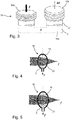
- Fig. 3 shows a hydraulic actuating element 18 as an exemplary embodiment for a micromechanical component according to the present invention.
- the hydraulic actuating element 18 contains a first cavity 10a, a second cavity 10b and a third cavity 10c connecting the two cavities.
- the three cavities 10a, 10b and 10c are delimited by hardened material 21.
- the wall thickness of the cured material 21 can be selected differently in different partial areas, so that the boundary walls of the cavities are either largely dimensionally stable or else deformable. In this way, the cavities 10a and 10b are enclosed by elastically deformable boundary walls which are deformable in the manner of a spring bellows.
- the cavity 10c is largely dimensionally stable and changes its volume only slightly or not at all.
- the micromechanical component shown thus represents a hydraulic actuating element which uses the liquid starting material 2 enclosed in the cavities 10a, 10b and 10c as hydraulic fluid.
- the Fig. 3 micromechanical component shown have a height of about 0.03 mm to about 3 mm or from about 0.1 mm to about 1.0 mm. In some embodiments of the invention, the Fig. 3 micromechanical component shown have a width of about 0.02 mm to about 10 mm or from about 0.05 mm to about 1.0 mm. Small details or structures can have a structure size of less than 0.8 ⁇ m or less than 0.2 ⁇ m.
- the Figures 4 and 5 explain the mode of operation of a lens 19 as an exemplary embodiment of a micromechanical component 1.
- the lens 19 in turn contains a cavity 10 which is delimited by hardened starting material 21.
- the cavity 10 is filled with liquid starting material 2.
- the boundary wall of the cavity 10 has a curvature so that electromagnetic radiation passing through the lens is focused on a focal point f.
- Fig. 5 shows, by increasing the pressure of the liquid starting material 2 in the cavity 10, a further deformation of the boundary surfaces of the lens 19 can be achieved, so that the curvature of the boundary surfaces increases and the refractive power of the lens 19 is increased. This changes the position of the focal point f.
- the lens 19 according to the invention can be used as a focusable microlens, so that the refractive index of the lens can be adapted during operation.
- the refractive power can be set once by adjusting the internal pressure to a desired value and fixed in this position by subsequent exposure and curing of the liquid starting material 2 inside the cavity 10.
- the Figures 4 and 5 micromechanical lens shown has a diameter of about 0.1 mm to about 1 mm or of about 0.3 mm to about 0.8 mm.
- the lens can be integrated with other optical or electronic components on a substrate to form a micro-optical chip.
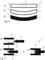
- Fig. 6 shows the subsequent adaptation of the shape of a micromechanical component.
- a micromechanical component is shown in the form of a rectangular parallelepiped which has a cavity 10.
- the cavity 10 is delimited by hardened starting material 21 and filled with liquid starting material 2.
- the shape can be adapted to a desired target shape.
- Figure 6b shows an example of the curvature of the initially rectangular cross-section so that, for example, the shape of a cylindrical lens results.
- the change in shape can also serve to produce a form fit to an adjacent component or to induce a mechanical stress in a boundary surface of the mechanical component or to influence the relative position of two components.
- Figure 6c shows the micromechanical component 1 after the entire content of the cavity 10 has been cured by exposure to a radiation source over a large area. Since the deformability of the micromechanical component in the second process step is essentially based on the fact that the boundary walls of the cavity are only thin-walled and therefore not mechanically stable and the liquid starting material 2 in the cavity 10 cannot transfer any shear forces, the micromechanical component 1 can, after the third Process step are fixed in this form, so that a subsequent undesired deformation is avoided.
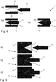
- Fig. 7 explains the production of a form-fitting connection between two micromechanical components 1a and 1b.
- the micromechanical component 1 a has a through hole or blind hole, on the inside of which a cavity 10 is formed which encloses the liquid starting material 2.
- the wall of the cavity 10 is made thin-walled so that the wall can be deformed.
- the second component 1b is shown in the form of an arrow in the exemplary embodiment. In other embodiments of the invention, a different shape can of course be chosen. It is only essential that a partial area can be introduced into the recess of the component 1 a and has a widening there, which leads to the deformation of the boundary wall of the cavity 10. This state is in Figure 7b shown. It can be seen that the boundary wall of the cavity 10 nestles against the shaft of the component 1b, the protruding parts acting like barbs.
- a firm, form-fitting and low-tension connection between components 1a and 1b can be established by optionally exposing the liquid starting material 2 to light.
- Fig. 8 shows a second embodiment of a form-fitting connection between two micromechanical components 1a and 1b. Same components of the invention are provided with the same reference symbols, so that the following description is limited to the essential differences.
- Figure 8b shows, the component 1b is pushed so far into the recess of the component 1a that the boundary surfaces of the cavity 10 are in full contact with the shaft of the component 1b. In this way, the cavity 10 assumes its original shape again after the component 1b has been introduced.
- the result in FIG Figure 8c shown completely tension-free fastening of the component 1b in the component 1a.
- the component 1b can remain axially displaceable, but without the component 1b being able to be separated from the component 1a.
- Fig. 9 shows a third embodiment of a connecting element according to the present invention.
- a component 1a and a component 1b should be permanently connected to one another.
- a cavity is produced in component 1a, the shape of which, in some embodiments of the invention, is complementary to a portion of component 1b.
- the cavity 10 is closed with a thin membrane made of solidified starting material in order to prevent liquid starting material 2 from escaping from the cavity.
- Figure 9b shows how the membrane pierces when the component 1b is introduced into the cavity 10 and the liquid starting material is thereby at least partially displaced from the cavity 10.
- the liquid starting material 10 adheres in the cavity 10 and to the component 1b in the area of the joint. By exposing the liquid starting material 2 to light, this solidifies, so that the solidified starting material 21 brings about a secure and tension-free connection of the two components 1a and 1b.
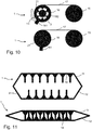
- Fig. 10 shows by way of example how a mechanical stress can be permanently impressed in a micromechanical component 1 during the manufacturing process.
- a string or a film 17 is shown as an example, which is pretensioned via two tensioning elements 15 and 16.
- the first tensioning element 15 consists essentially of continuously hardened starting material 21, which is produced from liquid starting material by local exposure to a radiation source.
- the string or the surface element 17 is produced in the liquid starting material by exposure to a focusable radiation source.
- the second tensioning element 16 has a stationary axis 162.
- the outer part of the tensioning element 16 is in punctiform contact with the axis 162 via reinforcing elements 13, so that cavities are formed between the outer part of the tensioning element and the axis 162, which are filled with liquid starting material 2, the outer part of the tensioning element around the Axis 162 is rotatable.
- the outer tensioning element 16 also has a lever 161. By applying a force to the lever 161, the outer tensioning element 16 can be rotated about the axis 162, so that the point contacts of the reinforcing elements 13 break off the axis 162 and a mechanical tension is impressed on the element 17. After the desired value has been reached, the material 2 can be cured in the cavities by exposure to light, so that the clamping element 16 is fixed in this position. As a result, the mechanical tension in the element 17 is permanently impressed.
- Fig. 11 shows a mechanical component 1, which is composed of a first partial structure 11 and a second partial structure 12. This allows the structure size of the mechanical component 1 after completion be less than is usually made possible by the manufacturing process, in that the structuring of one subcomponent engages in the interstices of the structuring of the other subcomponent.
- the mechanical component 1 according to Fig. 11 can for example be used as a filter for surface waves or microwaves.
Landscapes
- Engineering & Computer Science (AREA)
- Manufacturing & Machinery (AREA)
- Microelectronics & Electronic Packaging (AREA)
- Chemical & Material Sciences (AREA)
- Materials Engineering (AREA)
- Physics & Mathematics (AREA)
- Optics & Photonics (AREA)
- Mechanical Engineering (AREA)
- Computer Hardware Design (AREA)
- Micromachines (AREA)
Claims (13)
- Procédé de fabrication de composants micromécaniques (1), dans lequel un matériau de départ (2) liquide qui peut être durci par irradiation est appliqué sur un substrat, et
le matériau de départ est durci par irradiation locale avec une première source de rayonnement dans un volume partiel (21) pour produire au moins une structure tridimensionnelle,
caractérisé en ce que
la structure tridimensionnelle délimite au moins une cavité fermée (10) dans laquelle est enfermée une partie au moins du matériau de départ (2) liquide,
le rayonnement étant focalisé sur un point focal et une structure tridimensionnelle étant inscrite dans le matériau de départ par exposition point à point par sélection de la position focale. - Procédé selon la revendication 1,
caractérisé en ce que la cavité (10) contient au moins un élément de renforcement (13). - Procédé selon la revendication 1 ou 2,
caractérisé en ce que le matériau de départ (2) liquide enfermé dans la cavité (10) est transféré en phase gazeuse (22) lors d'une étape suivante du procédé. - Procédé selon l'une des revendications 1 ou 2,
caractérisé en ce que le matériau de départ (2) liquide enfermé dans la cavité (10) est durci dans une étape suivante du procédé par irradiation avec une seconde source de rayonnement. - Procédé selon l'une des revendications 1 ou 2,
caractérisé en ce que le matériau de départ (2) liquide enfermé dans la cavité (10) est pressurisée dans une étape suivante du procédé pour déformer la cavité (10). - Procédé selon l'une des revendications 3 ou 5,
caractérisé en ce qu'une contrainte mécanique est générée dans le matériau de départ (2) durci du composant micromécanique (1). - Procédé selon l'une des revendications 3 à 6,
caractérisé en ce qu'au moins deux composants micromécaniques (1a, 1b) sont assemblés l'un à l'autre par coopération de forme. - Procédé selon l'une des revendications 1 à 7,
caractérisé en ce que, pour fabriquer le composant micromécanique (1), un premier élément partiel (11) ayant une première structure et un second élément partiel (12) ayant une seconde structure sont assemblés l'un à l'autre. - Composant micromécanique (1) qui contient un matériau de départ (2) liquide durci partiellement par irradiation et qui présente au moins une cavité fermée (10) dans laquelle est enfermé le matériau de départ (2) liquide.
- Composant selon la revendication 9,
caractérisé en ce que la cavité (10) contient au moins un élément de renforcement (13). - Composant selon l'une des revendications 9 ou 10,
caractérisé en ce qu'il comprend au moins un élément d'actionnement hydraulique (18) et/ou au moins une lentille (19) et/ou au moins un élément de liaison. - Composant selon l'une des revendications 9 à 11,
caractérisé en ce que le matériau du composant (1) durci par irradiation présente une contrainte mécanique dans au moins une zone partielle (17). - Composant selon l'une des revendications 9 à 12,
caractérisé en ce qu'il comprend un méta-matériau présentant une pluralité de cavités (10) remplies chacune avec le matériau de départ (2) liquide.
Applications Claiming Priority (2)
| Application Number | Priority Date | Filing Date | Title |
|---|---|---|---|
| DE102014215061.2A DE102014215061A1 (de) | 2014-07-31 | 2014-07-31 | Mikromechanische Komponente und Verfahren zu ihrer Herstellung |
| PCT/EP2015/066064 WO2016015996A1 (fr) | 2014-07-31 | 2015-07-14 | Composant micromécanique et procédé de fabrication |
Publications (2)
| Publication Number | Publication Date |
|---|---|
| EP3174689A1 EP3174689A1 (fr) | 2017-06-07 |
| EP3174689B1 true EP3174689B1 (fr) | 2021-04-14 |
Family
ID=53773420
Family Applications (1)
| Application Number | Title | Priority Date | Filing Date |
|---|---|---|---|
| EP15745164.2A Active EP3174689B1 (fr) | 2014-07-31 | 2015-07-14 | Composant micromécanique et procédé de fabrication |
Country Status (5)
| Country | Link |
|---|---|
| US (1) | US10974958B2 (fr) |
| EP (1) | EP3174689B1 (fr) |
| CN (1) | CN106604809B (fr) |
| DE (1) | DE102014215061A1 (fr) |
| WO (1) | WO2016015996A1 (fr) |
Families Citing this family (8)
| Publication number | Priority date | Publication date | Assignee | Title |
|---|---|---|---|---|
| US11691341B2 (en) * | 2015-10-30 | 2023-07-04 | Seurat Technologies, Inc. | Part manipulation using printed manipulation points |
| CN106531286B (zh) * | 2016-12-26 | 2019-01-29 | 浙江晶科能源有限公司 | 一种刻蚀浆料及刻蚀方法 |
| CN109940879B (zh) * | 2017-12-20 | 2023-08-29 | 广州中国科学院先进技术研究所 | 一种新型可见光固化3d打印机的控制系统及方法 |
| US11667521B2 (en) * | 2019-08-26 | 2023-06-06 | City University Of Hong Kong | Method of constructing a micromechanical device |
| US12162074B2 (en) | 2020-11-25 | 2024-12-10 | Lawrence Livermore National Security, Llc | System and method for large-area pulsed laser melting of metallic powder in a laser powder bed fusion application |
| DE102021130981A1 (de) * | 2021-11-25 | 2023-05-25 | Bayerische Motoren Werke Aktiengesellschaft | Verfahren zur additiven Herstellung eines dreidimensionalen Objekts |
| DE102021131637A1 (de) | 2021-12-01 | 2023-06-01 | Bayerische Motoren Werke Aktiengesellschaft | Bauteil, umfassend wenigstens einen aus einem Baumaterial additiv hergestellten Festkörper |
| DE102022114623A1 (de) | 2022-06-10 | 2023-12-21 | Bayerische Motoren Werke Aktiengesellschaft | Verfahren zur additiven Herstellung eines wenigstens einen Dämpfungsabschnitt aufweisenden dreidimensionalen Objekts |
Family Cites Families (32)
| Publication number | Priority date | Publication date | Assignee | Title |
|---|---|---|---|---|
| JPS60179240A (ja) * | 1984-02-28 | 1985-09-13 | Inoue Mtp Co Ltd | 装飾モ−ルデイングの製造方法 |
| US4575330A (en) * | 1984-08-08 | 1986-03-11 | Uvp, Inc. | Apparatus for production of three-dimensional objects by stereolithography |
| US4752498A (en) * | 1987-03-02 | 1988-06-21 | Fudim Efrem V | Method and apparatus for production of three-dimensional objects by photosolidification |
| US5219712A (en) * | 1987-11-28 | 1993-06-15 | Thorn Emi Plc | Method of forming a solid article |
| IL109511A (en) | 1987-12-23 | 1996-10-16 | Cubital Ltd | Three-dimensional modelling apparatus |
| KR100257033B1 (ko) * | 1988-04-18 | 2000-06-01 | 찰스 윌리엄 헐 | 스테레오리소그래피를 사용하여 3차원 물체를 형성하기 위한 방법 및 장치 |
| US5137662A (en) * | 1988-11-08 | 1992-08-11 | 3-D Systems, Inc. | Method and apparatus for production of three-dimensional objects by stereolithography |
| US4999143A (en) * | 1988-04-18 | 1991-03-12 | 3D Systems, Inc. | Methods and apparatus for production of three-dimensional objects by stereolithography |
| US5171490A (en) * | 1988-11-29 | 1992-12-15 | Fudim Efrem V | Method and apparatus for production of three-dimensional objects by irradiation of photopolymers |
| DE3942859A1 (de) * | 1989-12-23 | 1991-07-04 | Basf Ag | Verfahren zur herstellung von bauteilen |
| US5204823A (en) * | 1991-03-20 | 1993-04-20 | Calcomp Inc. | Method and apparatus for high-speed layer thickness curing in 3-D model making |
| US5534101A (en) * | 1994-03-02 | 1996-07-09 | Telecommunication Research Laboratories | Method and apparatus for making optical components by direct dispensing of curable liquid |
| BE1008128A3 (nl) * | 1994-03-10 | 1996-01-23 | Materialise Nv | Werkwijze voor het ondersteunen van een voorwerp vervaardigd door stereolithografie of een andere snelle prototypevervaardigingswerkwijze en voor het vervaardigen van de daarbij gebruikte steunkonstruktie. |
| US5945058A (en) * | 1997-05-13 | 1999-08-31 | 3D Systems, Inc. | Method and apparatus for identifying surface features associated with selected lamina of a three-dimensional object being stereolithographically formed |
| US6641897B2 (en) * | 1998-02-13 | 2003-11-04 | The Milwaukee School Of Engineering | Three dimensional object |
| US6273478B1 (en) | 1999-03-30 | 2001-08-14 | The Regents Of The University Of California | Microfluidic interconnects |
| JP4786858B2 (ja) * | 2000-06-15 | 2011-10-05 | スリーエム イノベイティブ プロパティズ カンパニー | 封入光学素子を提供するための多光子硬化 |
| US6562278B1 (en) * | 2000-08-29 | 2003-05-13 | Micron Technology, Inc. | Methods of fabricating housing structures and micromachines incorporating such structures |
| US6786711B2 (en) * | 2001-06-08 | 2004-09-07 | The United States Of America As Represented By The Secretary Of The Navy | Method and system for production of fibrous composite prototypes using acoustic manipulation in stereolithography |
| WO2006018044A1 (fr) | 2004-08-18 | 2006-02-23 | Agilent Technologies, Inc. | Ensemble micro-fluidique comprenant des dispositifs micro-fluidiques couples |
| GB0420057D0 (en) | 2004-09-09 | 2004-10-13 | Level 5 Networks Ltd | Dynamic resource allocation |
| US7709544B2 (en) * | 2005-10-25 | 2010-05-04 | Massachusetts Institute Of Technology | Microstructure synthesis by flow lithography and polymerization |
| WO2010048279A2 (fr) * | 2008-10-21 | 2010-04-29 | Massachusetts Institute Of Technology | Polymérisation de déverrouillage |
| WO2009026520A1 (fr) * | 2007-08-23 | 2009-02-26 | 3D Systems, Inc. | Calibrage géométrique automatique utilisant une réflectométrie à balayage laser |
| DE102007048056A1 (de) | 2007-10-05 | 2009-04-09 | Zf Friedrichshafen Ag | Durchführungsvorrichtung für elektrische und hydraulische Leitungen an einem Wasserfahrzeug |
| DE102009000642B4 (de) * | 2009-02-05 | 2012-12-06 | BAM Bundesanstalt für Materialforschung und -prüfung | Verfahren zur Herstellung mikrostrukturierter Bauteile mittels Photolithographie |
| US20100219156A1 (en) * | 2009-03-02 | 2010-09-02 | Seagate Technology Llc | Three-dimensional magnetic structure for microassembly |
| CN101554758B (zh) * | 2009-04-09 | 2011-02-02 | 上海交通大学 | 利用纳米材料改性pdms制作热模压模具的方法 |
| US9492969B2 (en) * | 2010-05-28 | 2016-11-15 | Lawrence Livermore National Security, Llc | High resolution projection micro stereolithography system and method |
| DE102011105679B4 (de) | 2011-06-22 | 2019-03-28 | Nanoscribe Gmbh | Verfahren zum Herstellen dreidimensionaler Mikrostrukturen |
| KR101341216B1 (ko) * | 2012-11-29 | 2014-01-07 | 전남대학교산학협력단 | 광 리소그래피에 기초한 극저밀도 3차원 박막 구조체의 제조방법 |
| CN103913784A (zh) * | 2014-03-26 | 2014-07-09 | 中国科学院长春光学精密机械与物理研究所 | 一种聚合物微透镜阵列的制备方法 |
-
2014
- 2014-07-31 DE DE102014215061.2A patent/DE102014215061A1/de not_active Ceased
-
2015
- 2015-07-14 WO PCT/EP2015/066064 patent/WO2016015996A1/fr not_active Ceased
- 2015-07-14 EP EP15745164.2A patent/EP3174689B1/fr active Active
- 2015-07-14 CN CN201580040676.6A patent/CN106604809B/zh active Active
- 2015-07-14 US US15/500,430 patent/US10974958B2/en active Active
Non-Patent Citations (1)
| Title |
|---|
| None * |
Also Published As
| Publication number | Publication date |
|---|---|
| EP3174689A1 (fr) | 2017-06-07 |
| CN106604809B (zh) | 2019-06-11 |
| US20170210621A1 (en) | 2017-07-27 |
| WO2016015996A1 (fr) | 2016-02-04 |
| DE102014215061A1 (de) | 2016-02-04 |
| CN106604809A (zh) | 2017-04-26 |
| US10974958B2 (en) | 2021-04-13 |
Similar Documents
| Publication | Publication Date | Title |
|---|---|---|
| DE102014215061A1 (de) | Mikromechanische Komponente und Verfahren zu ihrer Herstellung | |
| EP3012688B1 (fr) | Procédé de fabrication d'une structure tridimensionnelle | |
| EP3266594B1 (fr) | Procédé et dispositif de fabrication générative par lithographie de composants tridimensionnels | |
| DE102015207158A1 (de) | Verfahren und Vorrichtung zum Herstellen eines dreidimensionalen Objekts | |
| EP2632673B1 (fr) | Procédé et dispositif pour fabriquer une pastille de lentille | |
| EP4288235A1 (fr) | Dispositif et procédé d'usinage au laser d'une pièce | |
| EP4288236A1 (fr) | Dispositif et procédé d'usinage au laser d'une pièce | |
| EP3802059B1 (fr) | Procédé de fabrication d'un arctile moule | |
| DE102013103059B4 (de) | Optische Linsenanordnung mit einem verformbaren Linsenkörper | |
| EP1284183A2 (fr) | Procédé et dispositif pour la moulage de lentilles optiques | |
| EP1349722A1 (fr) | Procede et dispositif pour l'assemblage de substrats | |
| DE102021108509A1 (de) | Vorrichtung und Verfahren zur Laserbearbeitung eines Werkstücks | |
| DE102016123344A1 (de) | Fertigungsanlage und Verfahren zur Herstellung eines Bauteils | |
| EP3175941A1 (fr) | Procédé et dispositif de fabrication par méthode additive d'au moins une partie d'un composant | |
| DE4200396C1 (fr) | ||
| DE102021108505A1 (de) | Vorrichtung und Verfahren zur Laserbearbeitung eines Werkstücks | |
| WO2015104182A1 (fr) | Dispositif de soudage par ultrasons | |
| DE102021103097B3 (de) | Lichtleiteranordnung und Verfahren zu deren Herstellung | |
| DE102008040854A1 (de) | Mikromechanische Struktur sowie Verfahren zum Einstellen der Arbeitsspaltbreite einer mikromechanischen Struktur | |
| DE102017201369B4 (de) | Verfahren zur unlösbaren Verbindung mittels eines Spreizniet sowie Spreizniet dazu | |
| EP4566802A1 (fr) | Procédé de fabrication d'une micro-optique | |
| DE102015212153A1 (de) | Druckvorrichtung zum Drucken einer dreidimensionalen Struktur | |
| DE10261558A1 (de) | Verfahren zum Herstellen eines diffraktiven optischen Bauteils | |
| DE102020132417A1 (de) | Verfahren und Vorrichtung zur Herstellung von mikroskopischen dreidimensionalen Multimaterialstrukturen | |
| DE102009054024A1 (de) | Elektronisch ansteuerbare Matrix-Maske |
Legal Events
| Date | Code | Title | Description |
|---|---|---|---|
| STAA | Information on the status of an ep patent application or granted ep patent |
Free format text: STATUS: THE INTERNATIONAL PUBLICATION HAS BEEN MADE |
|
| 17P | Request for examination filed |
Effective date: 20170217 |
|
| AK | Designated contracting states |
Kind code of ref document: A1 Designated state(s): AL AT BE BG CH CY CZ DE DK EE ES FI FR GB GR HR HU IE IS IT LI LT LU LV MC MK MT NL NO PL PT RO RS SE SI SK SM TR |
|
| AX | Request for extension of the european patent |
Extension state: BA ME |
|
| PUAI | Public reference made under article 153(3) epc to a published international application that has entered the european phase |
Free format text: ORIGINAL CODE: 0009012 |
|
| STAA | Information on the status of an ep patent application or granted ep patent |
Free format text: STATUS: REQUEST FOR EXAMINATION WAS MADE |
|
| DAV | Request for validation of the european patent (deleted) | ||
| DAX | Request for extension of the european patent (deleted) | ||
| GRAP | Despatch of communication of intention to grant a patent |
Free format text: ORIGINAL CODE: EPIDOSNIGR1 |
|
| STAA | Information on the status of an ep patent application or granted ep patent |
Free format text: STATUS: GRANT OF PATENT IS INTENDED |
|
| INTG | Intention to grant announced |
Effective date: 20201214 |
|
| GRAS | Grant fee paid |
Free format text: ORIGINAL CODE: EPIDOSNIGR3 |
|
| GRAA | (expected) grant |
Free format text: ORIGINAL CODE: 0009210 |
|
| STAA | Information on the status of an ep patent application or granted ep patent |
Free format text: STATUS: THE PATENT HAS BEEN GRANTED |
|
| AK | Designated contracting states |
Kind code of ref document: B1 Designated state(s): AL AT BE BG CH CY CZ DE DK EE ES FI FR GB GR HR HU IE IS IT LI LT LU LV MC MK MT NL NO PL PT RO RS SE SI SK SM TR |
|
| REG | Reference to a national code |
Ref country code: GB Ref legal event code: FG4D Free format text: NOT ENGLISH |
|
| REG | Reference to a national code |
Ref country code: CH Ref legal event code: EP |
|
| REG | Reference to a national code |
Ref country code: DE Ref legal event code: R096 Ref document number: 502015014563 Country of ref document: DE |
|
| REG | Reference to a national code |
Ref country code: IE Ref legal event code: FG4D Free format text: LANGUAGE OF EP DOCUMENT: GERMAN |
|
| REG | Reference to a national code |
Ref country code: CH Ref legal event code: NV Representative=s name: E. BLUM AND CO. AG PATENT- UND MARKENANWAELTE V, CH |
|
| REG | Reference to a national code |
Ref country code: AT Ref legal event code: REF Ref document number: 1381960 Country of ref document: AT Kind code of ref document: T Effective date: 20210515 |
|
| REG | Reference to a national code |
Ref country code: LT Ref legal event code: MG9D |
|
| REG | Reference to a national code |
Ref country code: NL Ref legal event code: MP Effective date: 20210414 |
|
| PG25 | Lapsed in a contracting state [announced via postgrant information from national office to epo] |
Ref country code: HR Free format text: LAPSE BECAUSE OF FAILURE TO SUBMIT A TRANSLATION OF THE DESCRIPTION OR TO PAY THE FEE WITHIN THE PRESCRIBED TIME-LIMIT Effective date: 20210414 Ref country code: BG Free format text: LAPSE BECAUSE OF FAILURE TO SUBMIT A TRANSLATION OF THE DESCRIPTION OR TO PAY THE FEE WITHIN THE PRESCRIBED TIME-LIMIT Effective date: 20210714 Ref country code: FI Free format text: LAPSE BECAUSE OF FAILURE TO SUBMIT A TRANSLATION OF THE DESCRIPTION OR TO PAY THE FEE WITHIN THE PRESCRIBED TIME-LIMIT Effective date: 20210414 Ref country code: LT Free format text: LAPSE BECAUSE OF FAILURE TO SUBMIT A TRANSLATION OF THE DESCRIPTION OR TO PAY THE FEE WITHIN THE PRESCRIBED TIME-LIMIT Effective date: 20210414 Ref country code: NL Free format text: LAPSE BECAUSE OF FAILURE TO SUBMIT A TRANSLATION OF THE DESCRIPTION OR TO PAY THE FEE WITHIN THE PRESCRIBED TIME-LIMIT Effective date: 20210414 |
|
| PG25 | Lapsed in a contracting state [announced via postgrant information from national office to epo] |
Ref country code: LV Free format text: LAPSE BECAUSE OF FAILURE TO SUBMIT A TRANSLATION OF THE DESCRIPTION OR TO PAY THE FEE WITHIN THE PRESCRIBED TIME-LIMIT Effective date: 20210414 Ref country code: IS Free format text: LAPSE BECAUSE OF FAILURE TO SUBMIT A TRANSLATION OF THE DESCRIPTION OR TO PAY THE FEE WITHIN THE PRESCRIBED TIME-LIMIT Effective date: 20210814 Ref country code: GR Free format text: LAPSE BECAUSE OF FAILURE TO SUBMIT A TRANSLATION OF THE DESCRIPTION OR TO PAY THE FEE WITHIN THE PRESCRIBED TIME-LIMIT Effective date: 20210715 Ref country code: NO Free format text: LAPSE BECAUSE OF FAILURE TO SUBMIT A TRANSLATION OF THE DESCRIPTION OR TO PAY THE FEE WITHIN THE PRESCRIBED TIME-LIMIT Effective date: 20210714 Ref country code: PT Free format text: LAPSE BECAUSE OF FAILURE TO SUBMIT A TRANSLATION OF THE DESCRIPTION OR TO PAY THE FEE WITHIN THE PRESCRIBED TIME-LIMIT Effective date: 20210816 Ref country code: PL Free format text: LAPSE BECAUSE OF FAILURE TO SUBMIT A TRANSLATION OF THE DESCRIPTION OR TO PAY THE FEE WITHIN THE PRESCRIBED TIME-LIMIT Effective date: 20210414 Ref country code: SE Free format text: LAPSE BECAUSE OF FAILURE TO SUBMIT A TRANSLATION OF THE DESCRIPTION OR TO PAY THE FEE WITHIN THE PRESCRIBED TIME-LIMIT Effective date: 20210414 Ref country code: RS Free format text: LAPSE BECAUSE OF FAILURE TO SUBMIT A TRANSLATION OF THE DESCRIPTION OR TO PAY THE FEE WITHIN THE PRESCRIBED TIME-LIMIT Effective date: 20210414 |
|
| REG | Reference to a national code |
Ref country code: DE Ref legal event code: R097 Ref document number: 502015014563 Country of ref document: DE |
|
| PG25 | Lapsed in a contracting state [announced via postgrant information from national office to epo] |
Ref country code: SM Free format text: LAPSE BECAUSE OF FAILURE TO SUBMIT A TRANSLATION OF THE DESCRIPTION OR TO PAY THE FEE WITHIN THE PRESCRIBED TIME-LIMIT Effective date: 20210414 Ref country code: SK Free format text: LAPSE BECAUSE OF FAILURE TO SUBMIT A TRANSLATION OF THE DESCRIPTION OR TO PAY THE FEE WITHIN THE PRESCRIBED TIME-LIMIT Effective date: 20210414 Ref country code: CZ Free format text: LAPSE BECAUSE OF FAILURE TO SUBMIT A TRANSLATION OF THE DESCRIPTION OR TO PAY THE FEE WITHIN THE PRESCRIBED TIME-LIMIT Effective date: 20210414 Ref country code: DK Free format text: LAPSE BECAUSE OF FAILURE TO SUBMIT A TRANSLATION OF THE DESCRIPTION OR TO PAY THE FEE WITHIN THE PRESCRIBED TIME-LIMIT Effective date: 20210414 Ref country code: EE Free format text: LAPSE BECAUSE OF FAILURE TO SUBMIT A TRANSLATION OF THE DESCRIPTION OR TO PAY THE FEE WITHIN THE PRESCRIBED TIME-LIMIT Effective date: 20210414 Ref country code: RO Free format text: LAPSE BECAUSE OF FAILURE TO SUBMIT A TRANSLATION OF THE DESCRIPTION OR TO PAY THE FEE WITHIN THE PRESCRIBED TIME-LIMIT Effective date: 20210414 Ref country code: ES Free format text: LAPSE BECAUSE OF FAILURE TO SUBMIT A TRANSLATION OF THE DESCRIPTION OR TO PAY THE FEE WITHIN THE PRESCRIBED TIME-LIMIT Effective date: 20210414 |
|
| PLBE | No opposition filed within time limit |
Free format text: ORIGINAL CODE: 0009261 |
|
| STAA | Information on the status of an ep patent application or granted ep patent |
Free format text: STATUS: NO OPPOSITION FILED WITHIN TIME LIMIT |
|
| 26N | No opposition filed |
Effective date: 20220117 |
|
| PG25 | Lapsed in a contracting state [announced via postgrant information from national office to epo] |
Ref country code: MC Free format text: LAPSE BECAUSE OF FAILURE TO SUBMIT A TRANSLATION OF THE DESCRIPTION OR TO PAY THE FEE WITHIN THE PRESCRIBED TIME-LIMIT Effective date: 20210414 |
|
| REG | Reference to a national code |
Ref country code: BE Ref legal event code: MM Effective date: 20210731 |
|
| PG25 | Lapsed in a contracting state [announced via postgrant information from national office to epo] |
Ref country code: IS Free format text: LAPSE BECAUSE OF FAILURE TO SUBMIT A TRANSLATION OF THE DESCRIPTION OR TO PAY THE FEE WITHIN THE PRESCRIBED TIME-LIMIT Effective date: 20210814 Ref country code: AL Free format text: LAPSE BECAUSE OF FAILURE TO SUBMIT A TRANSLATION OF THE DESCRIPTION OR TO PAY THE FEE WITHIN THE PRESCRIBED TIME-LIMIT Effective date: 20210414 Ref country code: LU Free format text: LAPSE BECAUSE OF NON-PAYMENT OF DUE FEES Effective date: 20210714 |
|
| PG25 | Lapsed in a contracting state [announced via postgrant information from national office to epo] |
Ref country code: BE Free format text: LAPSE BECAUSE OF NON-PAYMENT OF DUE FEES Effective date: 20210731 |
|
| REG | Reference to a national code |
Ref country code: AT Ref legal event code: MM01 Ref document number: 1381960 Country of ref document: AT Kind code of ref document: T Effective date: 20210714 |
|
| PG25 | Lapsed in a contracting state [announced via postgrant information from national office to epo] |
Ref country code: AT Free format text: LAPSE BECAUSE OF NON-PAYMENT OF DUE FEES Effective date: 20210714 |
|
| PG25 | Lapsed in a contracting state [announced via postgrant information from national office to epo] |
Ref country code: HU Free format text: LAPSE BECAUSE OF FAILURE TO SUBMIT A TRANSLATION OF THE DESCRIPTION OR TO PAY THE FEE WITHIN THE PRESCRIBED TIME-LIMIT; INVALID AB INITIO Effective date: 20150714 |
|
| P01 | Opt-out of the competence of the unified patent court (upc) registered |
Effective date: 20230524 |
|
| PG25 | Lapsed in a contracting state [announced via postgrant information from national office to epo] |
Ref country code: CY Free format text: LAPSE BECAUSE OF FAILURE TO SUBMIT A TRANSLATION OF THE DESCRIPTION OR TO PAY THE FEE WITHIN THE PRESCRIBED TIME-LIMIT Effective date: 20210414 |
|
| PG25 | Lapsed in a contracting state [announced via postgrant information from national office to epo] |
Ref country code: MK Free format text: LAPSE BECAUSE OF FAILURE TO SUBMIT A TRANSLATION OF THE DESCRIPTION OR TO PAY THE FEE WITHIN THE PRESCRIBED TIME-LIMIT Effective date: 20210414 |
|
| PG25 | Lapsed in a contracting state [announced via postgrant information from national office to epo] |
Ref country code: MT Free format text: LAPSE BECAUSE OF FAILURE TO SUBMIT A TRANSLATION OF THE DESCRIPTION OR TO PAY THE FEE WITHIN THE PRESCRIBED TIME-LIMIT Effective date: 20210414 |
|
| PGFP | Annual fee paid to national office [announced via postgrant information from national office to epo] |
Ref country code: DE Payment date: 20250722 Year of fee payment: 11 |
|
| PGFP | Annual fee paid to national office [announced via postgrant information from national office to epo] |
Ref country code: IT Payment date: 20250731 Year of fee payment: 11 |
|
| PGFP | Annual fee paid to national office [announced via postgrant information from national office to epo] |
Ref country code: GB Payment date: 20250724 Year of fee payment: 11 |
|
| PGFP | Annual fee paid to national office [announced via postgrant information from national office to epo] |
Ref country code: FR Payment date: 20250723 Year of fee payment: 11 |
|
| PGFP | Annual fee paid to national office [announced via postgrant information from national office to epo] |
Ref country code: CH Payment date: 20250801 Year of fee payment: 11 |
|
| PGFP | Annual fee paid to national office [announced via postgrant information from national office to epo] |
Ref country code: IE Payment date: 20250724 Year of fee payment: 11 |
|
| PG25 | Lapsed in a contracting state [announced via postgrant information from national office to epo] |
Ref country code: TR Free format text: LAPSE BECAUSE OF FAILURE TO SUBMIT A TRANSLATION OF THE DESCRIPTION OR TO PAY THE FEE WITHIN THE PRESCRIBED TIME-LIMIT Effective date: 20210414 |