EP3174792B1 - Système de siège d'avion - Google Patents
Système de siège d'avion Download PDFInfo
- Publication number
- EP3174792B1 EP3174792B1 EP15745183.2A EP15745183A EP3174792B1 EP 3174792 B1 EP3174792 B1 EP 3174792B1 EP 15745183 A EP15745183 A EP 15745183A EP 3174792 B1 EP3174792 B1 EP 3174792B1
- Authority
- EP
- European Patent Office
- Prior art keywords
- area
- seat
- bench
- region
- passenger
- Prior art date
- Legal status (The legal status is an assumption and is not a legal conclusion. Google has not performed a legal analysis and makes no representation as to the accuracy of the status listed.)
- Active
Links
Images


Classifications
-
- B—PERFORMING OPERATIONS; TRANSPORTING
- B64—AIRCRAFT; AVIATION; COSMONAUTICS
- B64D—EQUIPMENT FOR FITTING IN OR TO AIRCRAFT; FLIGHT SUITS; PARACHUTES; ARRANGEMENT OR MOUNTING OF POWER PLANTS OR PROPULSION TRANSMISSIONS IN AIRCRAFT
- B64D11/00—Passenger or crew accommodation; Flight-deck installations not otherwise provided for
- B64D11/06—Arrangements of seats, or adaptations or details specially adapted for aircraft seats
- B64D11/0639—Arrangements of seats, or adaptations or details specially adapted for aircraft seats with features for adjustment or converting of seats
- B64D11/0641—Seats convertible into beds
-
- B—PERFORMING OPERATIONS; TRANSPORTING
- B64—AIRCRAFT; AVIATION; COSMONAUTICS
- B64D—EQUIPMENT FOR FITTING IN OR TO AIRCRAFT; FLIGHT SUITS; PARACHUTES; ARRANGEMENT OR MOUNTING OF POWER PLANTS OR PROPULSION TRANSMISSIONS IN AIRCRAFT
- B64D11/00—Passenger or crew accommodation; Flight-deck installations not otherwise provided for
- B64D11/06—Arrangements of seats, or adaptations or details specially adapted for aircraft seats
- B64D11/0602—Seat modules, i.e. seat systems including furniture separate from the seat itself
- B64D11/0604—Seat modules, i.e. seat systems including furniture separate from the seat itself including a bed, e.g. cocoon type passenger seat modules
-
- B—PERFORMING OPERATIONS; TRANSPORTING
- B64—AIRCRAFT; AVIATION; COSMONAUTICS
- B64D—EQUIPMENT FOR FITTING IN OR TO AIRCRAFT; FLIGHT SUITS; PARACHUTES; ARRANGEMENT OR MOUNTING OF POWER PLANTS OR PROPULSION TRANSMISSIONS IN AIRCRAFT
- B64D11/00—Passenger or crew accommodation; Flight-deck installations not otherwise provided for
- B64D11/06—Arrangements of seats, or adaptations or details specially adapted for aircraft seats
- B64D11/0627—Seats combined with storage means
- B64D11/0636—Personal storage means or waste disposal bags
Definitions
- the invention relates to an aircraft seat system according to the preamble of patent claim 1.
- an aircraft seat system with at least one passenger seat area, which has at least one seat area and at least one bench area, which is arranged in a transverse direction, at least substantially perpendicular to a seat direction, on one side of the seat area and has a bench surface which is in at least one operating state forms a lying surface with at least one seat bottom unit of the seating area.
- US 2007/152100 A1 discloses an aircraft seat system with a passenger seat area which has a seat area and a bench area which is arranged perpendicular to a seating direction on one side of the seat area and has a bench surface which forms a lying surface with a seat bottom unit of the seat area.
- the seat base unit is offset to the rear from the one bench area.
- DE 10 2012 020846 A1 discloses an aircraft seating system with at least one passenger seating area, which has at least one seating area and at least one bench area, which is provided so that a passenger can sit on it during a flight, the bench area being oriented in a transverse direction at least substantially perpendicular to a seating direction Side of the seating area is arranged and has a bench surface that forms a lying surface with at least one seat bottom unit of the seating area in at least one operating state, a further passenger seating area being arranged behind the one passenger seating area and also forming a seating area that is parallel to the seating direction behind the a bank area is arranged.
- EP 2 733073 A1 discloses a vehicle seat having a seat unit and a bench unit, the bench unit being arranged on a side of the seat unit in a transverse direction perpendicular to a longitudinal direction of a seat unit.
- the bank unit points in at least a seat position on a bank unit portion that projects beyond the seat unit with respect to the longitudinal direction of the seat unit.
- WO 2006/054104 A1 discloses a passenger seat bed with a seat unit having a seating area and a backrest and an adjacent piece of furniture with an upper surface, wherein a sleeping configuration of the seat bed, the seating area of the seat and the upper surface of the adjacent piece of furniture form a substantially flat sleeping surface.
- the object of the invention is, in particular, to provide a generic device with improved properties with regard to comfort and privacy for a passenger.
- the object is achieved by the features of claim 1, while advantageous refinements and developments of the invention can be found in the subclaims.
- the invention is based on an aircraft seat system with at least one passenger seat area, which has at least one seat area and at least one bench area, which is arranged in a transverse direction, at least substantially perpendicular to a seat direction, on one side of the seat area and has a bench surface which in at least in an operating state with at least one seat bottom unit of the seat area forms a lying surface, the seat bottom unit being offset to the rear from the at least one bench area.
- the aircraft seat system have a further passenger seat area which is arranged behind the one passenger seat area and likewise forms a seat area which is arranged parallel to the seat direction behind the one bench area.
- a passenger seat area should in particular an area can be understood that a person has available to him in an aircraft cabin, in particular during a flight.
- an aircraft seat area preferably has a plurality of add-on elements for use by a passenger, such as a table shelf, a monitor or storage options.
- a “seat area” is to be understood in particular to mean an area of a passenger seat area which is provided for a passenger to sit on it during a flight.
- the seating area is preferably formed by an air passenger seat.
- a “passenger seat” is to be understood in particular to mean a seat which is intended to be erected on a cabin floor in an aircraft cabin of an aircraft and on which a passenger can sit during a flight.
- the passenger seat has a seat bottom unit and a backrest unit coupled to the seat bottom unit, the backrest unit preferably being pivotably connected to the seat bottom unit, as a result of which the passenger seat can preferably be moved into different functional positions.
- a “seat base unit” is to be understood in particular to mean an element which forms a seat surface of the passenger seat on which the passenger sits during a flight, the seat base unit preferably having at least one cushion unit which elastically cushions the seat surface.
- a “bench area” is to be understood to mean an area of the passenger seat area which is provided so that a passenger can sit on it during a flight and / or at least parts of his body can rest thereon.
- the bench area is intended to expand the seating area of the passenger seat.
- a “seat direction” is to be understood in particular as a direction which essentially corresponds to the direction in which the thighs of the passenger extend from the buttocks to the knee area when a passenger is seated properly, in particular with the thighs of the passenger oriented in parallel.
- the seat direction is oriented parallel to the floor and at least substantially perpendicular to the backrest surface formed by the backrest unit.
- a "transverse direction” is to be understood in particular to mean a direction oriented orthogonally to the seat direction, which is in an upright position of the passenger seat, in which a backrest unit is oriented at least substantially perpendicular to a floor, and which is from one side of the seat area to an opposite one Side of the seating area runs.
- a surface there should be a surface can be understood, which is provided by the bench area, the bench surface being intended to be used by a passenger as a shelf for objects or for resting at least areas of his body.
- a "lying surface” is to be understood in particular to mean a surface which is provided so that a passenger can lie thereon in an extended manner.
- offset to the rear is to be understood in particular to mean that at least partial areas, in particular a rear partial area of the seat base unit, are offset to the rear, that is to say in particular counter to the seat direction, with a rear end of the bench unit further forward in relation to the seat direction is arranged as a rear end of the seat bottom unit.
- a “rear end of the seat base unit” is to be understood in particular to mean a rear edge of the seat base unit which, as seen in the seat direction, is arranged furthest to the rear.
- the rear end of the seat base unit is in particular formed by an edge at which the seat base unit merges into the backrest unit.
- the backrest extends upward away from a stand unit.
- a “further passenger seat area” is to be understood in particular to mean a passenger seat area which is intended for another passenger. The further passenger seat area is separated from the one passenger seat area. “Arranged behind the passenger seat area” is to be understood here in particular in relation to a flight direction behind the one passenger seat area.
- a configuration according to the invention can advantageously provide a passenger seat area which advantageously shields a seated passenger from a rest of an aircraft cabin, as a result of which particularly advantageous privacy can be achieved for a passenger seated in the passenger seat area. Due to the rearward-shifted seating area, the rest of the passenger seating area advantageously partially shields the seating area and thus the passenger from a corridor area. In addition, a further passenger seating area can be integrated into an aircraft cabin.
- a rear end of the seat base unit is offset to the rear by at least 100 mm to a rear end of the one bench area.
- a “rear end of the bench area” is to be understood in particular to mean a rear edge of the bench area which, viewed in a sitting direction, protrudes the furthest rearward over the seating area.
- the rear end of the bench area is in particular formed by an edge at which the bench area merges into a shell element.
- the shell element extends upwards, away from the stand level.
- “By at least 100 mm” is to be understood to mean in particular by at least 100 mm, preferably by 150 mm and in an advantageous embodiment by at least 250 mm.
- the at least one passenger seat area has a further bench area which is arranged on a side of the seat area opposite the one bench area.
- a “further bank area” is to be understood in particular to mean a bank area that is spatially separate from the at least one bank area.
- the at least one passenger seat area has at least one pivotably arranged bench element, which is arranged at a front end of the bench areas and the seat area and extends the lying surface in a folded-out position.
- “At least one bench element” is to be understood in particular to mean that at least one pivotably arranged bench element is arranged in the passenger seat area, but it is in principle also conceivable that two, three or more pivotably arranged bench elements can be arranged in the passenger seat area.
- the several bench elements can be adjusted independently of one another, which means that either a complete lying area, a smaller lying area or, in particular, an independent, temporary, additional seat can be provided.
- a “pivotably arranged bench element” is to be understood in particular to mean an element that is adjustable at least between two positions and has a bench element surface that is aligned in at least one position parallel and even to the bench surfaces and the seat surface in order to form a flat lying surface, wherein the bench element can be pivoted between the at least two different positions.
- the bench element can be locked in the two positions between which it is adjustable. It is basically also conceivable that a bench element can be locked in various intermediate positions that lie between the two positions, between which the bench element is adjustable. An intermediate position could be formed, for example, by a comfort position in which the bench element is approximately at an angle of 45 degrees to the stand level.
- the bench element is preferably infinitely adjustable between the two positions.
- the pivotably arranged bench element is preferably pivotably coupled to the bench areas and the seat area via a hinge device.
- a "unfolded position” in particular a working position of the pivotable bench element is to be sanded, in which the bench element is moved out of its folded position, the bench element the lying area is expanded and can be used by a passenger in the unfolded position.
- the pivotable bench element is preferably locked in the unfolded position, in particular to prevent undesired swiveling out into the folded position.
- a "folded position” is to be understood in particular to mean a stowed position of the pivotable bench element, in which the bench element is folded onto the bench areas and the seat area and thereby takes up as little space as possible, the pivotable bench element in the folded position not expanding and extending the lying surface cannot be used by a passenger.
- the pivotable bench element is preferably locked in the folded position, which in particular prevents undesired pivoting out of the folded position.
- a lying surface provided for the passenger can be made particularly large and, in an operating state in which it is not required, can advantageously be stowed with little space requirement.
- the at least one pivotably arranged bench element extends in a transverse direction over both bench areas and the seating area.
- "To extend over both bench areas and the seating area” should be understood in particular to mean that a transverse extension of the pivotable bench element is essentially as large as a transverse extension of the two bench areas and the seating area together, the bench element extending from one side of the one bench area the bench area, further over the seating area and then over the further bench area to an end of the further bench area facing away from the seating area.
- the lying surface can be made particularly large and an entire width of the bench areas can be used in combination with the seating area.
- the passenger seat area be oriented obliquely to the flight direction.
- a “flight direction” is to be understood in particular to mean a main direction of extension of the aircraft, the direction of flight extending from a rear of the aircraft to a bow of the aircraft and preferably running coaxially to a central axis of the aircraft.
- “Aligned obliquely to the flight direction” is to be understood in this context in particular to mean that a seat direction of the passenger seat area has an angle to the flight direction that is between 10 degrees and 40 degrees, preferably is between 30 degrees and 35 degrees.
- the angle that the seat direction of the passenger seat area has to the flight direction is in particular distinguished from 90 degrees. A particularly advantageous division of passenger seat areas in an aircraft cabin can thereby be achieved.
- the passenger seat area have at least one table device which has a folded and an unfolded position, the table device also being usable in the folded position.
- a “table device” is to be understood in particular to mean a device which provides at least one table surface on which a passenger can place things in the passenger seat area.
- a “folded-in position of the table device” is to be understood in particular to mean a position of the table device in which the table device forms a minimally possible table surface and in particular occupies a minimal space in the passenger seat area.
- a "unfolded position” is to be understood in particular to mean a position of the table device in which the table device forms the maximum possible table surface.
- the table device preferably has a plurality of unfolded positions in which the table device is aligned in different positions with respect to the seating area of the passenger seating area.
- “usable” is to be understood in particular to mean that elements which form the table device can be deposited on the table surface.
- a table device can advantageously be provided which, depending on the situation, can provide a larger or smaller table surface for storage for the passenger, which in particular increases comfort for the passenger.
- the table device have a transverse extent that is greater than a transverse extent of the seating area.
- a “transverse extension” is to be understood in particular to mean an extension of the table device that is oriented essentially orthogonally to a seating direction of the seating area. This enables a particularly advantageous table device to be provided.
- the seating area be formed by an air passenger seat that can be manually adjusted between at least two functional positions.
- a “functional position” is to be understood in particular to mean a position of the passenger seat in which the passenger seat can be adjusted to sit by a passenger sitting on it, as desired.
- a "TTL position” is to be understood in particular to mean an upright position of the passenger seat which must be assumed for safety reasons, in particular in a take-off phase, in a landing phase and during turbulence.
- the backrest unit of the passenger seat and the seat bottom unit are essentially perpendicular to one another, preferably at an angle of between 90 degrees and 105 degrees.
- a second functional position is designed as a comfort position in which the backrest unit is tilted from the TTL position to the seat base unit.
- the passenger seat in particular cannot be brought into a functional position, which represents a lying position in which the backrest unit is essentially parallel to the seat bottom unit.
- a passenger can advantageously occupy different seating positions while seated in the seating area, which in particular increases seating comfort for the passenger.
- the bench area has at least one pivotable cover, which partially forms the lying surface in a folded state
- the passenger seat area has at least one storage space which is arranged below the bench area and is accessible to the pivotable cover in an opened state.
- a “pivotable cover” is to be understood in particular to mean a pivotable element which is provided in a folded-in state for covering another element, such as in particular the storage space.
- a “storage space” is to be understood in particular to mean a space that can be used by a passenger to store luggage or other elements. This advantageously and easily creates a storage space in the aircraft seat area for the passenger.
- the aircraft seat system has a console area which is assigned to the further passenger seat area and which is arranged in an area behind the one bench area.
- a “console area” is to be understood in particular to mean an area of the passenger seat area in which add-on elements and operating elements for a passenger are arranged in the passenger seat area, such as, in particular, a screen, a table device or a storage device.
- the further passenger seat area can be configured particularly advantageously and the two passenger seat areas can be designed for an advantageous division in the aircraft cabin.
- the further bench area has a backrest area that connects to a backrest unit of the seating area.
- a particularly large area can advantageously be provided, against which a passenger can lean with his back.
- the backrest area has a pivotable cover that forms an armrest in an unfolded state.
- an armrest can advantageously be provided for the passenger.
- the backrest area has an oblique upholstery that faces the seating area.
- “Oblique upholstery” is to be understood in particular to mean upholstery that is pivoted in a vertical axis to the rest of the backrest area and protrudes forward from the rest of the backrest area.
- the aircraft seat system have a padded wall that closes off the passenger seat area on a side of the bench area facing away from the seat area.
- the passenger seat area can advantageously be closed off in the area of one bank area.
- Aircraft seat system for fulfilling a function described herein have a number that differs from a number of individual elements, components and units mentioned here.
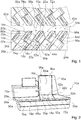
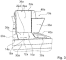
- the Figures 1 to 4 show a first embodiment of an aircraft seat system according to the invention.
- the aircraft seat system is part of an aircraft, not shown.
- the aircraft comprises a partially illustrated aircraft cabin 24a, in which the aircraft seat system is arranged.
- the aircraft cabin 24a forms a cabin floor 60a.
- the cabin floor 60a forms an elevation level of the aircraft cabin 24a.
- the aircraft seat system comprises a first passenger seat area 10a.
- the passenger seat area 10a is oriented obliquely to a flight direction 32a.
- the first passenger seat area 10a comprises a first passenger seat 36a.
- the passenger seat 36a includes a seat bottom unit 22a and a backrest unit 50a.
- the seat bottom unit 22a and the backrest unit 50a are pivotally coupled to one another.
- the backrest unit 50a is arranged at a rear end of the seat bottom unit 22a.
- the backrest unit 50a is arranged essentially orthogonally to the seat bottom unit 22a.
- the seat bottom unit 22a forms a seat surface 62a.
- the seat surface 62a is padded and is provided so that a passenger can sit on it.
- the seat surface 62a is oriented essentially parallel to the cabin floor 60a.
- the backrest unit 50a forms a backrest surface 64a against which a passenger sitting on the passenger seat 36a can lean with his back.
- the passenger seat 36a forms a seat direction 16a.
- the seat direction 16a forms the direction in which a passenger normally sits on the passenger seat 36a.
- the seat direction 16a In a vertical position of the backrest unit 50a, the seat direction 16a is orthogonal to the backrest surface 64a and is directed forward in the direction of the seat bottom unit 22a.
- the passenger seat 36a forms a transverse direction 18a.
- the transverse direction 18a is oriented orthogonally to the seat direction 16a.
- the passenger seat 36a is displaceable between two functional positions.
- a first functional position is designed as a TTL position. In the functional position designed as a TTL position, the passenger seat 36a is in an upright position.
- the backrest unit 50a is oriented essentially perpendicular to the cabin floor 60a and the seat bottom unit 22a is oriented essentially orthogonally to the backrest unit 50a.
- a second functional position is designed as a comfort position in which the backrest unit 50a is deflected from the substantially vertical position and is oriented obliquely to the cabin floor 60a is.
- the seat bottom unit 22a is likewise deflected to the position oriented essentially parallel to the cabin floor 60a and is angled to the cabin floor 60a.
- the backrest unit 50a and the seat base unit 22a are oriented at an angle to one another in the functional position designed as a comfort position.
- the passenger seat 36a is infinitely adjustable between the two functional positions. In this case, the passenger seat 36a cannot be brought into a functional position designed as a lying position, in which the seat bottom unit 22a and the backrest unit 50a together form a lying surface which is oriented in the seat direction 16a.
- the passenger seat area 10a has a seat area 12a.
- the seating area 12a is formed by the passenger seat 36a.
- the seat bottom unit 22a of the passenger seat 36a defines the seat area 12a of the passenger seat area 10a.
- the passenger seat area 10a has a first bench area 14a.
- the first bench area 14a is arranged on the first side of the seat area 12a in the transverse direction 18a oriented perpendicular to the seat direction 16a.
- the first bench area 14a is arranged on one side of the seat area 12a, which faces an aircraft aisle 66a.
- the first bench area 14a forms a bench surface 20a.
- the bench surface 20a is flat with the seat surface 62a of the seat bottom unit 22a.
- a front edge 68a of the bench area 14a is flat to a front edge 70a of the seat area 12a.
- the front edge 68a of the first bench area 14a and the front edge 70a of the seat area 12a are oriented orthogonally to the seat direction 16a in the transverse direction 18a.
- the seat base unit 22a is offset to the rear from the first bench area 14a in the seat direction 16a.
- a rear end of the seat bottom unit 22a is offset to the rear end of the bench area 14a.
- the rear end of the seat bottom unit 22a is arranged further back in the seat direction 16a than the rear end of the first bench area 14a.
- the seat bottom unit 22a has a depth extension in the seat direction 16a that is greater than a depth extension of the first bench area 14a.
- the first bench area 14a is made narrower in the seat direction 16a than the seat bottom unit 22a and thus the seat area 12a of the passenger seat area 10a.
- the seat base unit 22a is offset by 500 mm to the first bench area 14a to the rear.
- the rear end of the seat bottom unit 22a is offset 250 mm further back in the seat direction 16a than the rear end of the first bench area 14a.
- a distance from the rear end the seat bottom unit 22a to its front edge 70a, measured in the seat direction 16a, is 500 mm larger than a distance from the rear end of the first bench area 14a to its front edge 68a.
- the passenger seat area 10a has a shell element 72a.
- the shell element 72a at least partially separates the seating area 12a from a rest of the aircraft cabin 24a. In a region of the first bank region 14a, the shell element 72a directly adjoins the rear end of the first bank region 14a and extends upwards.
- the shell element 72a extends in the transverse direction 18a from an aisle-facing end of the passenger seat area 10a over an entire width of the first bench area 14a. At a transition from the first bench area 14a to the seating area 12a, the shell element 72a extends rearward until behind the backrest unit 50a of the passenger seat 36a.
- the shell element 72a extends to an end of the passenger seat region 10a facing away from the aisle.
- the shell element 72a conceals the part of the seat bottom unit 22a which is set backwards in the direction of the aircraft aisle 66a.
- the passenger seat area 10a has a second bench area 28a.
- the second bench area 28a is arranged on a side of the seat area 12a or the seat bottom unit 22a opposite the first bench area 14a.
- the second bench area 28a has a front edge 74a which is in alignment with the front edge 70a of the seat area 12a and the front edge 68a of the first bench area 14a.
- the second bench area 28a has a depth that is approximately identical to the depth of the seat area 12a.
- the second bench area 28a extends in the seat direction 16a from its front edge 74a to the rear as far as the seat area 12a from its front edge 70a.
- the second bench area 28a extends in the transverse direction 18a from the seat area 12a to the end of the passenger seat area 10a facing away from the aisle.
- the further bench area 28a has a backrest area 48a.
- the backrest area 48a directly adjoins the backrest unit 50a of the seating area 12a.
- the two bank areas 14a, 28a together with the seat bottom unit 22a of the seat area 12a form a lying surface 26a of the passenger seat area 10a.
- the lying surface 26a is designed as a surface on which a passenger can lie oriented in the transverse direction 18a.
- a lying direction in which a passenger lies on the lying surface 26a formed by the bench areas 14a, 28a and the seating area 12a is oriented orthogonally to the sitting direction 16a. The passenger can lie comfortably stretched out on the lying surface 26a.
- the passenger seat area 10a has a pivotably arranged bench element 30a.
- the pivotably arranged bench element 30a is arranged at a front end of the bench areas 14a, 28a and the seating area 12a.
- the pivotably arranged bench element 30a directly adjoins the front edges 68a, 70a, 74a of the bench areas 14a, 28a and the seating area 12a.
- the pivotably arranged bench element 30a is connected to the bench areas 14a, 28a and the seat area 12a by means of a bearing device (not shown in more detail).
- the bearing device is preferably formed by a plurality of hinges and / or kinematics.
- the pivotably arranged bench element 30a has a folded state and an unfolded state.
- the bench element 30a In the folded state, the bench element 30a is oriented essentially in a vertical position.
- the bench element 30a is folded against a front area of the passenger seat area 10a.
- the passenger seat area 10a forms a stowage receptacle in which the bench element 30a is stowed in a space-saving manner in the folded state.
- the bench element 30a In the folded state, the bench element 30a does not protrude into an area of the passenger seat area 10a provided for the passenger.
- the bench element 30a can be locked in the folded position by means of a locking device (not shown in more detail).
- the bench element 30a In the unfolded position, the bench element 30a is provided to enlarge the lying surface 26a.
- the bench element 30a In the unfolded position, the bench element 30a is aligned with the bench areas 14a, 28a and the seating area 12a.
- the bench element 30a forms an additional surface 76a which, when the bench element 30a is unfolded, is just aligned with the bench surfaces 20a of the bench areas 14a, 28a and the seat surface 62a.
- the bench element 30a extends the lying surface 26a with its additional surface 76a.
- the bench element 30a can be locked in the unfolded position by means of the locking device (not shown). Due to the pivotably arranged bench element 30a, a passenger can enlarge the lying surface 26a if necessary, whereby the bench element 30a can advantageously be folded away and stowed away in a space-saving manner when not in use.
- the pivotably arranged bench element 30a extends in the transverse direction 18a over the two bench areas 14a, 28a and the seating area 12a.
- the bench element 30a extends on the front edges 68a, 70a, 74a of the bench areas 14a, 28a and the seat area 12a from the end of the passenger seat area 10a facing the aisle to the end of the passenger seat area 10a facing away from the aisle.
- the bench element 30a increases the lying surface 26a over both bench areas 14a, 28a and the seating area 12a in an unfolded state.
- the passenger seat area 10a comprises a table device 34a.
- the table device 34a is arranged in a console area 78a of the first passenger seat area 10a.
- the console area 78a of the first passenger seat area 10a is formed by a shell element 80a of a further passenger seat area 82a arranged in front of the first passenger seat area 10a.
- the table device 34a has a transverse extent which is greater than a transverse extent, that is to say an extension of the seat base unit 22a in the transverse direction 18a.
- the table device 34a has a folded position and a folded position.
- the table device 34a can be used both in the unfolded position and in the folded position.
- the table device 34a has a base plate 84a.
- the base plate 84a is rigidly connected to the shell element 80a.
- the base plate 84a of the table device 34a can always be used by a passenger.
- the base plate 84a forms part of the table surface, which is accessible to a passenger both in a folded-in state and in a folded-out state of the table device 34a.
- the table device 34a has an additional plate 86a.
- the additional plate 86a is movably mounted to the base plate 84a of the table device 34a.
- the additional plate 86a is in the folded position of the table device 34a in a rest position and does not expand the table surface. When the table device 34a is in an extended position, the additional plate 86a is in a functional position and expands the table surface.
- the passenger seat area 10a further comprises a monitor 92a.
- the monitor 92a is arranged in the console area 78a of the first passenger seat area 10a.
- the monitor 92a is mounted above the table device 34a in the console area 78a.
- the monitor 92a is pivotally connected in the console area 78a.
- the monitor 92a can be pivoted such that it can be both by a passenger sitting in the seating area 12a and by the passenger can easily be viewed by a passenger lying on the lying surface 26a.
- the monitor 92a can be aligned by pivoting substantially orthogonally to the seat direction 16a or optionally also essentially orthogonally to the transverse direction 18a.
- the monitor 92a is infinitely adjustable.
- the second bench area 28a has a pivotable cover 38a.
- the pivotable cover can be pivoted between a folded state and an opened state.
- the pivotable cover 38a is pivotally mounted at a rear end via a hinge device, not shown.
- the pivotable cover 38a forms the lying surface 26a, which the second bench area 28a provides.
- the pivotable cover 38a is pivoted upward with a front end.
- the passenger seat area 10a further includes a storage space 40a.
- the storage space 40a is arranged in an area below the second bench area 28a.
- the storage space 40a arranged below the bench area 28a is open at the top.
- the storage space 40a is accessible to a passenger from above.
- a passenger in the passenger seat area 10a can simply stow utensils and hand luggage under the bench area 28a in the storage space 40a.
- the aircraft seat system comprises a further passenger seat area 42a.
- the further passenger seat area 42a viewed in the direction of flight 32a, is arranged behind the first passenger seat area 10a.
- the further passenger seat area 42a likewise forms a seat area 44a which is arranged parallel to the seat direction 16a behind the first bench area 14a.
- the further passenger seat area 42a is essentially identical to the first passenger seat area 10a, which is why this will not be described in more detail here.
- the aircraft seat system comprises a console area 46a which is assigned to the further passenger seat area 42a.
- the console area 46a is arranged in an area immediately behind the first bench area 14a.
- the console area 46a is formed by the shell element 72a, which is still formed at the front in the area of the first bench area 14a in the seat direction 16a.
- the console area 46a of the further passenger seat area 42a is arranged behind the narrow first bench area 14a, as a result of which an advantageous nesting of the passenger seat areas 10a, 42a can be achieved and the passenger seat areas 10a, 42a advantageously close can be mounted on each other, whereby a particularly advantageous packing density of the passenger seat areas 10a, 42a can be achieved.
- the aircraft seat system further comprises a storage space 90a, which is also assigned to the further passenger seat area 42a.
- a passenger who travels in the further passenger seat area 42a can accommodate travel items such as hand luggage or smaller items such as a laptop or a cell phone in a travel-safe manner.
- the storage space 90a has a cover, not shown, with which the storage space 90a can be closed to the outside.
- An aircraft cabin 24a with an aircraft seat system with a plurality of passenger seat areas 10a, 42a is shown. In this case, three passenger seat areas 10a, 42a are arranged in a row of seats transverse to the direction of flight 32a. A first row of passenger seat areas 10a, 42a is arranged on a first side of the aircraft cabin 24a.
- a second row of passenger seat areas (not shown) is arranged through a corridor area separated from the first row of passenger seat areas 10a, 42a.
- the second row of passenger seating areas is arranged centrally in the aircraft cabin 24a and forms a middle row.
- a third row of passenger seat areas (not shown) is arranged on a second side of the aircraft cabin 24a by means of a corridor area separated from the second row of passenger seat areas.
- the passenger seat areas of the second and third rows which are not described in any more detail, are essentially of the same design as the passenger seat areas 10a, 42a of the first row.
- the middle third row it would also be conceivable for the middle third row to be formed from two passenger seat areas arranged next to one another, thus achieving a herringbone arrangement of the passenger seat areas 10a, 42a in the aircraft cabin 24a.
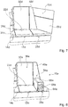
- the Figure 5 shows a second embodiment of an aircraft seat system according to the invention.
- the aircraft seat system comprises a first passenger seat area 10b.
- the first passenger seat area 10b is configured essentially the same as the first passenger seat area from the first exemplary embodiment from FIGS Figures 1 to 4 and is therefore only roughly described below. Corresponding features of the passenger seat area 10b can be adopted from the description of the first exemplary embodiment.
- the first passenger seat area 10b includes a first passenger seat 36b.
- the passenger seat 36b includes a seat bottom unit 22b and a backrest unit 50b.
- the passenger seat area 10b has a seat area 12b.
- the seating area 12b is formed by the passenger seat 36b.
- the passenger seat area 10b has a first bench area 14b.
- the first bench area 14b is arranged on a first side of the seating area 12b in a transverse direction 18b oriented perpendicular to the seating direction.
- the passenger seat area 10b has a second bench area 28b.
- the second bench area 28b is arranged on a side of the seat area 12b or the seat bottom unit 22b opposite the first bench area 14b.
- the further bench area 28b has a backrest area 48b.
- the backrest area 48b directly adjoins the backrest unit 50b of the seating area 12b.
- the second bank area 28b differs from the second bank area of the first embodiment.
- the backrest area 48b of the second bench area 28b comprises a pivotable cover 52b.
- the pivotable cover 52b can be pivoted between a folded state and an unfolded state.
- the pivotable cover 52b In the folded state, the pivotable cover 52b is folded onto the backrest area 48b. In an unfolded state, the pivotable cover 52b is folded away from the backrest area 48b and forms an armrest 54b. The pivotable cover 52b protrudes from the backrest area 48b at an angle of approximately 90 degrees. The pivotable cover 52b, which is provided to form the armrest 54b, can be locked in the folded and unfolded state.
- the Figure 6 shows a third embodiment of an aircraft seat system according to the invention.
- the aircraft seat system comprises a first passenger seat area 10c.
- the first passenger seat area 10c is configured essentially the same as the first passenger seat area from the first exemplary embodiment from FIGS Figures 1 to 4 and is therefore only roughly described below. Corresponding characteristics of the passenger seating area 10c can be taken from the description of the first exemplary embodiment.
- the first passenger seat area 10c comprises a first passenger seat 36c.
- the passenger seat 36c includes a seat bottom unit 22c and a backrest unit 50c.
- the passenger seat area 10c has a seat area 12c.
- the seating area 12c is formed by the passenger seat 36c.
- the passenger seat area 10c has a first bench area 14c.
- the first bench area 14c is arranged on a first side of the seating area 12c in a transverse direction 18c oriented perpendicular to the seating direction.
- the passenger seat area 10c has a second bench area 28c.
- the second bench area 28c is arranged on a side of the seat area 12c or the seat bottom unit 22c opposite the first bench area 14c.
- the further bench area 28c has a backrest area 48c.
- the backrest area 48c directly adjoins the backrest unit 50c of the seating area 12c.
- the second bank area 28c differs from the second bank area of the first embodiment.
- the backrest area 48c of the second bench area 28c has an oblique padding 56c.
- the oblique padding 56c faces the seating area 12c.
- a side of the oblique padding 56c facing the seating area 12c is arranged further back in the flight direction than a side of the oblique padding 56c facing away from the seating area 12c.
- the Figure 7 shows a fourth embodiment of an aircraft seat system according to the invention.
- the aircraft seat system comprises a first passenger seat area 10d.
- the first passenger seat area 10d is configured essentially the same as the first passenger seat area from the first exemplary embodiment from FIGS Figures 1 to 4 and is therefore only roughly described below. Corresponding features of the passenger seat area 10d can be adopted from the description of the first exemplary embodiment.
- the first passenger seat area 10d includes a first passenger seat 36d.
- the passenger seat 36d includes a seat bottom unit 22d and a backrest unit 50d.
- the passenger seat area 10d has a seat area 12d.
- the seating area 12d is formed by the passenger seat 36d.
- the passenger seat area 10d has a first bench area 14d.
- the first bench area 14d is arranged on a first side of the seating area 12d in a transverse direction 18d oriented perpendicular to the sitting direction.
- the passenger seat area 10d has a second bench area 28d.
- the second bench area 28d is arranged on a side of the seat area 12d or the seat bottom unit 22d opposite the first bench area 14d.
- the further bank area 28d has one Backrest area 48d.
- the backrest area 48d directly adjoins the backrest unit 50d of the seating area 12d.
- the passenger seat area 10d comprises a padded wall 58d which closes the passenger seat area 10d on a side of the second bench area 28d facing away from the seat area 12d.
- the padded wall 58d closes off the passenger seat area 10d at an end facing away from the aisle.
- the padded wall 58d has the same height as the backrest area 48d of the second bench area 28d.
- FIG 8 shows a fifth embodiment of an aircraft seat system according to the invention.
- the aircraft seat system comprises a first passenger seat area 10e.
- the first passenger seat area 10e is configured essentially the same as the first passenger seat area from the first exemplary embodiment from FIGS Figures 1 to 4 and is therefore only roughly described below. Corresponding features of the passenger seat area 10e can be adopted from the description of the first exemplary embodiment.
- the first passenger seat area 10e comprises a first passenger seat 36e.
- the passenger seat 36e includes a seat bottom unit 22e and a backrest unit 50e.
- the passenger seat area 10e has a seat area 12e.
- the seating area 12e is formed by the passenger seat 36e.
- the passenger seat area 10e has a first bench area 14e.
- the first bench area 14e is arranged on a first side of the seating area 12e in a transverse direction 18e oriented perpendicular to the seating direction.
- the passenger seat area 10e has a second bench area 28e.
- the second bench area 28e is arranged on a side of the seat area 12e or the seat bottom unit 22e opposite the first bench area 14e.
- the further bench area 28e has a backrest area 48e.
- the backrest area 48e directly adjoins the backrest unit 50e of the seating area 12e.
- the bench area 28e has an armrest 88e.
- the armrest 88e is formed as part of the bench area 28e.
- the armrest 88e is integrated in the bench area 28e.
- the armrest 88e In a retracted state, the armrest 88e forms a bench surface 94e of the bench area 28e. In the retracted state, the armrest 88e is retracted into the bench area 28e. In an extended state, the armrest 88e extends upward from the bench surface 94e of the bench area 28e away from the bench surface 94e. In the extended state, a passenger sitting in the passenger seat area 10e can place an arm on the armrest 88e.
- the bench area 28e has a linear guide device, not shown on. The armrest 88e is connected to the bench area 28 via the linear guide device.
- the armrest 88e has a baffle element 96e on a front side which faces away from the backrest region 48e. Small items such as a cell phone, glasses or the like can be stowed in the storage element 96e.
- the baffle element 96e is designed to be closable. In Figure 8 the armrest 88e is shown in the extended state.
Landscapes
- Engineering & Computer Science (AREA)
- Aviation & Aerospace Engineering (AREA)
- Seats For Vehicles (AREA)
Claims (15)
- Système assise d'avion avec au moins une zone assise de passager d'avion (10a ; 10b ; 10c ; 10d) comprenant au moins une zone de siège (12a ; 12b ; 12c ; 12d) et au moins une zone de banc (14a ; 14b ; 14c ; 14d) prévue pour qu'un passager s'y puisse asseoir,
où la zone de banc (14a ; 14b ; 14c ; 14d) est disposée à un côté de la zone de siège (12a ; 12b ; 12c ; 12d) dans une direction transversale (18a) orientée au moins sensiblement perpendiculairement à une direction d'assise (16a) et comporte une superficie de banc (20a ; 20b ; 20c ; 20d) qui forme, en au moins un état d'opération, une surface de couchage (26a ; 26b ; 26c ; 26d) avec au moins unité fond de siège (22a ; 22b ; 22c ; 22d) de la zone de siège (12a ; 12b ; 12c ; 12d),
où l'unité fond de siège (22a ; 22b ; 22c ; 22d) est, par rapport à l'au moins une zone de banc (14a ; 14b ; 14c ; 14d), décalée vers l'arrière dans la direction d'assise (16a)
le système assise d'avion comprenant une zone assise de passager d'avion de plus (42a), qui est disposée derrière l'une zone assise de passager d'avion (10a) et aussi forme une zone de siège (44a) disposée en parallèle à la direction d'assise (16a) derrière l'une zone de banc (14a). - Système assise d'avion selon la revendication 1,
caractérisé en ce qu'une partie arrière de l'unité fond de siège (22a ; 22b ; 22c ; 22d) est décalée par rapport à une partie arrière de l'une zone de banc (14a ; 14b ; 14c ; 14d) par au moins 100 mm vers l'arrière. - Système assise d'avion selon la revendication 1 ou 2,
caractérisé en ce que l'au moins une zone assise de passager d'avion (10a ; 10b ; 10c ; 10d) comporte une zone de banc de plus (28a ; 28b ; 28c ; 28d) disposée sur un côté de la zone de siège (12a ; 12b ; 12c ; 12d) opposé à l'une zone de banc (14a ; 14b ; 14c ; 14d). - Système assise d'avion selon l'une quelconque des revendications précédentes,
caractérisé en ce que l'au moins une zone assise de passager d'avion (10a) comporte au moins un élément de banc (30a) qui est disposé d'une manière pivotable, qui est disposé à une partie antérieure des zones de banc (14a, 28a) et de la zone de siège (12a) et qui en état déployé élargisse la surface de couchage (26a). - Système assise d'avion selon la revendication 4,
caractérisé en ce que l'au moins un élément de banc (30a) disposé d'une manière pivotable s'étend dans la direction transversale (18a) au travers des deux zones de banc (14a, 28a) et de la zone de siège (12a). - Système assise d'avion selon l'une quelconque des revendications précédentes,
caractérisé en ce que la zone assise de passager d'avion (10a) est orientée obliquement à une direction de vol (32a). - Système assise d'avion selon l'une quelconque des revendications précédentes,
caractérisé en ce que la zone assise de passager d'avion (10a) comporte au moins un dispositif de table (34a) ayant une position rebattue et une position déployée, le dispositif de table (34a) étant utilisable aussi dans la position répliée. - Système assise d'avion selon la revendication 7,
caractérisé en ce que le dispositif de table (34a) comporte une extension transversale qui est plus large qu'une extension transversale de la zone de siège (12a). - Système assise d'avion selon l'une quelconque des revendications précédentes,
caractérisé en ce que la zone de siège (12a) est implémentée par un siège de passager d'avion (36a), qui est manuellement ajustable entre au moins deux positions fonctionnelles. - Système assise d'avion selon l'une quelconque des revendications précédentes,
caractérisé en ce que la zone de banc (28a) comporte au moins une couverture pivotable (38a) formant dans son état rebattu partiellement la surface de couchage (26a), et que la zone assise de passager d'avion (10a) comporte au moins un espace de rangement (40a), qui est agencé au-dessous de la zone de banc (28a) et est accessible en état déployé de la couverture pivotable (38a). - Système assise d'avion selon l'une quelconque des revendications précédentes,
caractérisé par une zone console (46a) allouée à la zone assise de passager d'avion de plus (42a), qui est disposée dans une région derrière l'une zone de banc (14a). - Système assise d'avion au moins selon la revendication 3,
caractérisé en ce que la zone de banc de plus (28a ; 28b, 28c ; 28d) comporte une zone de dossier (48a ; 48b ; 48c ; 48d) se joignante à une unité de dossier (50a ; 50b ; 50c ; 50d) de la zone de siège (12a ; 12b ; 12c ; 12d). - Système assise d'avion au moins selon la revendication 12,
caractérisé en ce que la zone de dossier (48b) comprend une couverture pivotable (52b) formant en état déployé un dossier (54b). - Système assise d'avion au moins selon la revendication 12,
caractérisé en ce que la zone de dossier (48c) comprend un rembourrage oblique (56c) tourné vers la zone de siège (12c). - Système assise d'avion selon l'une quelconque des revendications précédentes,
caractérisé par une paroi rembourrée (58d) terminant la zone assise de passager d'avion (10d) sur un côté de la zone de banc (28d) tourné vers la zone de siège (12d).
Applications Claiming Priority (2)
| Application Number | Priority Date | Filing Date | Title |
|---|---|---|---|
| DE102014110819.1A DE102014110819A1 (de) | 2014-07-30 | 2014-07-30 | Flugzeugsitzsystem |
| PCT/EP2015/067421 WO2016016326A1 (fr) | 2014-07-30 | 2015-07-29 | Système de siège d'avion |
Publications (2)
| Publication Number | Publication Date |
|---|---|
| EP3174792A1 EP3174792A1 (fr) | 2017-06-07 |
| EP3174792B1 true EP3174792B1 (fr) | 2020-07-29 |
Family
ID=53773436
Family Applications (1)
| Application Number | Title | Priority Date | Filing Date |
|---|---|---|---|
| EP15745183.2A Active EP3174792B1 (fr) | 2014-07-30 | 2015-07-29 | Système de siège d'avion |
Country Status (3)
| Country | Link |
|---|---|
| EP (1) | EP3174792B1 (fr) |
| DE (1) | DE102014110819A1 (fr) |
| WO (1) | WO2016016326A1 (fr) |
Families Citing this family (5)
| Publication number | Priority date | Publication date | Assignee | Title |
|---|---|---|---|---|
| DE102018130231A1 (de) * | 2018-11-29 | 2020-06-04 | Airbus Operations Gmbh | Multifunktionale Sitzanordnung für eine Passagierkabine eines Fahrzeugs |
| DE102019115618A1 (de) * | 2019-06-07 | 2020-12-10 | Recaro Aircraft Seating Gmbh & Co. Kg | Flugzeugsitzvorrichtung |
| US11498681B2 (en) | 2020-01-14 | 2022-11-15 | B/E Aerospace, Inc. | Integrated seating armrest, stowage and bed surface |
| US11613359B2 (en) | 2020-01-15 | 2023-03-28 | B/E Aerospace, Inc. | Bench-back aircraft seat for aircraft passenger compartment suites |
| US11230382B2 (en) | 2020-02-05 | 2022-01-25 | B/E Aerospace, Inc. | Combined divan aircraft seat for aircraft passenger compartment suites |
Citations (1)
| Publication number | Priority date | Publication date | Assignee | Title |
|---|---|---|---|---|
| GB2438162A (en) * | 2006-05-19 | 2007-11-21 | British Airways Plc | Reclining aircraft seat convertible into bed |
Family Cites Families (8)
| Publication number | Priority date | Publication date | Assignee | Title |
|---|---|---|---|---|
| GB0425606D0 (en) * | 2004-11-20 | 2004-12-22 | Newberry Jocelyn M F | Passenger seat and bed |
| FR2883838B1 (fr) * | 2005-03-31 | 2007-06-08 | Eads Sogerma Services Soc Par | Piece de mobilier pour vehicule, notamment pour aeronef |
| US7770845B2 (en) * | 2005-06-10 | 2010-08-10 | Airbus | Double module for aircraft passenger(s) |
| WO2007061381A1 (fr) * | 2005-11-24 | 2007-05-31 | Singapore Airlines Limited | Agencements de siege et siege d’avion |
| FR2928624B1 (fr) * | 2008-03-17 | 2016-07-15 | Soc Ind Et Commerciale De Materiel Aeronautique - Sicma Aero Seat | Agencement d'accoudoir de siege en epi securise siege et ensemble de deux sieges muni d'un tel agencement. |
| US8876202B2 (en) * | 2009-07-16 | 2014-11-04 | The Boeing Company | Berth sleeper system |
| DE102012020847A1 (de) * | 2012-10-24 | 2014-04-24 | Recaro Aircraft Seating Gmbh & Co. Kg | Fahrzeugsitz |
| DE102012020846A1 (de) * | 2012-10-24 | 2014-04-24 | Recaro Aircraft Seating Gmbh & Co. Kg | Fahrzeugsitz |
-
2014
- 2014-07-30 DE DE102014110819.1A patent/DE102014110819A1/de not_active Withdrawn
-
2015
- 2015-07-29 WO PCT/EP2015/067421 patent/WO2016016326A1/fr not_active Ceased
- 2015-07-29 EP EP15745183.2A patent/EP3174792B1/fr active Active
Patent Citations (1)
| Publication number | Priority date | Publication date | Assignee | Title |
|---|---|---|---|---|
| GB2438162A (en) * | 2006-05-19 | 2007-11-21 | British Airways Plc | Reclining aircraft seat convertible into bed |
Also Published As
| Publication number | Publication date |
|---|---|
| DE102014110819A1 (de) | 2016-02-04 |
| EP3174792A1 (fr) | 2017-06-07 |
| WO2016016326A1 (fr) | 2016-02-04 |
Similar Documents
| Publication | Publication Date | Title |
|---|---|---|
| DE10214104C1 (de) | Fahrzeugsitz, insbesondere Fluggastsitz | |
| EP1142750B1 (fr) | Agencement de sièges de véhicules | |
| EP3344541B1 (fr) | Dispositif siège d'aéronef comprenant un siège d'aéronef rabattable | |
| EP3174792B1 (fr) | Système de siège d'avion | |
| EP1932713B1 (fr) | Siège central pour une banquette arrière de véhicule automobile | |
| DE102019102510A1 (de) | Fahrzeugsitzanordnung mit ausschwenkbaren polstern | |
| DE20000479U1 (de) | Sitzbank-Anordnung für Fahrzeuge | |
| EP3122631B1 (fr) | Système de siège d'avion | |
| DE102019102094A1 (de) | Fahrzeugsitzanordnung mit staulösungen | |
| EP1759991A1 (fr) | Arrangement permettant de s'assoir et de s'allonger | |
| EP2440459A1 (fr) | Dispositif de sièges pour passagers | |
| DE60223843T2 (de) | Kraftfahrzeugsitz mit einer kniestütze | |
| WO2018185109A1 (fr) | Dispositif siège d'aéronef | |
| EP4330137B1 (fr) | Ensemble siège d'aéronef | |
| EP2733073B1 (fr) | Siège de véhicule | |
| EP2443033A2 (fr) | Système de siège passager | |
| DE102015005669A1 (de) | Fondsitz mit einer Armlehne für ein Fahrzeug | |
| DE102015218357B4 (de) | Fahrzeugsitz | |
| EP4126671A1 (fr) | Agencement de sièges d'avion | |
| DE202016102640U1 (de) | Flugzeugdivan | |
| DE102015218354B4 (de) | Fahrzeugsitz | |
| DE102005029131A1 (de) | Cabrioletfahrzeug mit einem Windschott | |
| DE102021117964A1 (de) | Flugzeugsitzanordnung | |
| DE102019115618A1 (de) | Flugzeugsitzvorrichtung | |
| DE102006036042B4 (de) | Sitzanordnung für Kraftfahrzeug |
Legal Events
| Date | Code | Title | Description |
|---|---|---|---|
| STAA | Information on the status of an ep patent application or granted ep patent |
Free format text: STATUS: THE INTERNATIONAL PUBLICATION HAS BEEN MADE |
|
| 17P | Request for examination filed |
Effective date: 20170223 |
|
| AK | Designated contracting states |
Kind code of ref document: A1 Designated state(s): AL AT BE BG CH CY CZ DE DK EE ES FI FR GB GR HR HU IE IS IT LI LT LU LV MC MK MT NL NO PL PT RO RS SE SI SK SM TR |
|
| AX | Request for extension of the european patent |
Extension state: BA ME |
|
| PUAI | Public reference made under article 153(3) epc to a published international application that has entered the european phase |
Free format text: ORIGINAL CODE: 0009012 |
|
| STAA | Information on the status of an ep patent application or granted ep patent |
Free format text: STATUS: REQUEST FOR EXAMINATION WAS MADE |
|
| RIN1 | Information on inventor provided before grant (corrected) |
Inventor name: CLUCAS, DANIEL WILLIAM Inventor name: ERSAN, ALI |
|
| DAV | Request for validation of the european patent (deleted) | ||
| DAX | Request for extension of the european patent (deleted) | ||
| STAA | Information on the status of an ep patent application or granted ep patent |
Free format text: STATUS: EXAMINATION IS IN PROGRESS |
|
| 17Q | First examination report despatched |
Effective date: 20171109 |
|
| GRAP | Despatch of communication of intention to grant a patent |
Free format text: ORIGINAL CODE: EPIDOSNIGR1 |
|
| STAA | Information on the status of an ep patent application or granted ep patent |
Free format text: STATUS: GRANT OF PATENT IS INTENDED |
|
| INTG | Intention to grant announced |
Effective date: 20200212 |
|
| GRAS | Grant fee paid |
Free format text: ORIGINAL CODE: EPIDOSNIGR3 |
|
| GRAA | (expected) grant |
Free format text: ORIGINAL CODE: 0009210 |
|
| STAA | Information on the status of an ep patent application or granted ep patent |
Free format text: STATUS: THE PATENT HAS BEEN GRANTED |
|
| AK | Designated contracting states |
Kind code of ref document: B1 Designated state(s): AL AT BE BG CH CY CZ DE DK EE ES FI FR GB GR HR HU IE IS IT LI LT LU LV MC MK MT NL NO PL PT RO RS SE SI SK SM TR |
|
| REG | Reference to a national code |
Ref country code: CH Ref legal event code: EP |
|
| REG | Reference to a national code |
Ref country code: AT Ref legal event code: REF Ref document number: 1295494 Country of ref document: AT Kind code of ref document: T Effective date: 20200815 |
|
| REG | Reference to a national code |
Ref country code: IE Ref legal event code: FG4D Free format text: LANGUAGE OF EP DOCUMENT: GERMAN |
|
| REG | Reference to a national code |
Ref country code: DE Ref legal event code: R096 Ref document number: 502015013122 Country of ref document: DE |
|
| REG | Reference to a national code |
Ref country code: LT Ref legal event code: MG4D |
|
| REG | Reference to a national code |
Ref country code: NL Ref legal event code: MP Effective date: 20200729 |
|
| PG25 | Lapsed in a contracting state [announced via postgrant information from national office to epo] |
Ref country code: PT Free format text: LAPSE BECAUSE OF FAILURE TO SUBMIT A TRANSLATION OF THE DESCRIPTION OR TO PAY THE FEE WITHIN THE PRESCRIBED TIME-LIMIT Effective date: 20201130 Ref country code: FI Free format text: LAPSE BECAUSE OF FAILURE TO SUBMIT A TRANSLATION OF THE DESCRIPTION OR TO PAY THE FEE WITHIN THE PRESCRIBED TIME-LIMIT Effective date: 20200729 Ref country code: GR Free format text: LAPSE BECAUSE OF FAILURE TO SUBMIT A TRANSLATION OF THE DESCRIPTION OR TO PAY THE FEE WITHIN THE PRESCRIBED TIME-LIMIT Effective date: 20201030 Ref country code: LT Free format text: LAPSE BECAUSE OF FAILURE TO SUBMIT A TRANSLATION OF THE DESCRIPTION OR TO PAY THE FEE WITHIN THE PRESCRIBED TIME-LIMIT Effective date: 20200729 Ref country code: HR Free format text: LAPSE BECAUSE OF FAILURE TO SUBMIT A TRANSLATION OF THE DESCRIPTION OR TO PAY THE FEE WITHIN THE PRESCRIBED TIME-LIMIT Effective date: 20200729 Ref country code: SE Free format text: LAPSE BECAUSE OF FAILURE TO SUBMIT A TRANSLATION OF THE DESCRIPTION OR TO PAY THE FEE WITHIN THE PRESCRIBED TIME-LIMIT Effective date: 20200729 Ref country code: BG Free format text: LAPSE BECAUSE OF FAILURE TO SUBMIT A TRANSLATION OF THE DESCRIPTION OR TO PAY THE FEE WITHIN THE PRESCRIBED TIME-LIMIT Effective date: 20201029 Ref country code: NO Free format text: LAPSE BECAUSE OF FAILURE TO SUBMIT A TRANSLATION OF THE DESCRIPTION OR TO PAY THE FEE WITHIN THE PRESCRIBED TIME-LIMIT Effective date: 20201029 Ref country code: ES Free format text: LAPSE BECAUSE OF FAILURE TO SUBMIT A TRANSLATION OF THE DESCRIPTION OR TO PAY THE FEE WITHIN THE PRESCRIBED TIME-LIMIT Effective date: 20200729 |
|
| PG25 | Lapsed in a contracting state [announced via postgrant information from national office to epo] |
Ref country code: RS Free format text: LAPSE BECAUSE OF FAILURE TO SUBMIT A TRANSLATION OF THE DESCRIPTION OR TO PAY THE FEE WITHIN THE PRESCRIBED TIME-LIMIT Effective date: 20200729 Ref country code: PL Free format text: LAPSE BECAUSE OF FAILURE TO SUBMIT A TRANSLATION OF THE DESCRIPTION OR TO PAY THE FEE WITHIN THE PRESCRIBED TIME-LIMIT Effective date: 20200729 Ref country code: LV Free format text: LAPSE BECAUSE OF FAILURE TO SUBMIT A TRANSLATION OF THE DESCRIPTION OR TO PAY THE FEE WITHIN THE PRESCRIBED TIME-LIMIT Effective date: 20200729 Ref country code: IS Free format text: LAPSE BECAUSE OF FAILURE TO SUBMIT A TRANSLATION OF THE DESCRIPTION OR TO PAY THE FEE WITHIN THE PRESCRIBED TIME-LIMIT Effective date: 20201129 |
|
| REG | Reference to a national code |
Ref country code: CH Ref legal event code: PL |
|
| PG25 | Lapsed in a contracting state [announced via postgrant information from national office to epo] |
Ref country code: NL Free format text: LAPSE BECAUSE OF FAILURE TO SUBMIT A TRANSLATION OF THE DESCRIPTION OR TO PAY THE FEE WITHIN THE PRESCRIBED TIME-LIMIT Effective date: 20200729 |
|
| REG | Reference to a national code |
Ref country code: BE Ref legal event code: MM Effective date: 20200731 |
|
| PG25 | Lapsed in a contracting state [announced via postgrant information from national office to epo] |
Ref country code: LI Free format text: LAPSE BECAUSE OF NON-PAYMENT OF DUE FEES Effective date: 20200731 Ref country code: CZ Free format text: LAPSE BECAUSE OF FAILURE TO SUBMIT A TRANSLATION OF THE DESCRIPTION OR TO PAY THE FEE WITHIN THE PRESCRIBED TIME-LIMIT Effective date: 20200729 Ref country code: DK Free format text: LAPSE BECAUSE OF FAILURE TO SUBMIT A TRANSLATION OF THE DESCRIPTION OR TO PAY THE FEE WITHIN THE PRESCRIBED TIME-LIMIT Effective date: 20200729 Ref country code: CH Free format text: LAPSE BECAUSE OF NON-PAYMENT OF DUE FEES Effective date: 20200731 Ref country code: IT Free format text: LAPSE BECAUSE OF FAILURE TO SUBMIT A TRANSLATION OF THE DESCRIPTION OR TO PAY THE FEE WITHIN THE PRESCRIBED TIME-LIMIT Effective date: 20200729 Ref country code: EE Free format text: LAPSE BECAUSE OF FAILURE TO SUBMIT A TRANSLATION OF THE DESCRIPTION OR TO PAY THE FEE WITHIN THE PRESCRIBED TIME-LIMIT Effective date: 20200729 Ref country code: RO Free format text: LAPSE BECAUSE OF FAILURE TO SUBMIT A TRANSLATION OF THE DESCRIPTION OR TO PAY THE FEE WITHIN THE PRESCRIBED TIME-LIMIT Effective date: 20200729 Ref country code: SM Free format text: LAPSE BECAUSE OF FAILURE TO SUBMIT A TRANSLATION OF THE DESCRIPTION OR TO PAY THE FEE WITHIN THE PRESCRIBED TIME-LIMIT Effective date: 20200729 Ref country code: LU Free format text: LAPSE BECAUSE OF NON-PAYMENT OF DUE FEES Effective date: 20200729 Ref country code: MC Free format text: LAPSE BECAUSE OF FAILURE TO SUBMIT A TRANSLATION OF THE DESCRIPTION OR TO PAY THE FEE WITHIN THE PRESCRIBED TIME-LIMIT Effective date: 20200729 |
|
| REG | Reference to a national code |
Ref country code: DE Ref legal event code: R097 Ref document number: 502015013122 Country of ref document: DE |
|
| PG25 | Lapsed in a contracting state [announced via postgrant information from national office to epo] |
Ref country code: BE Free format text: LAPSE BECAUSE OF NON-PAYMENT OF DUE FEES Effective date: 20200731 Ref country code: AL Free format text: LAPSE BECAUSE OF FAILURE TO SUBMIT A TRANSLATION OF THE DESCRIPTION OR TO PAY THE FEE WITHIN THE PRESCRIBED TIME-LIMIT Effective date: 20200729 |
|
| PLBE | No opposition filed within time limit |
Free format text: ORIGINAL CODE: 0009261 |
|
| STAA | Information on the status of an ep patent application or granted ep patent |
Free format text: STATUS: NO OPPOSITION FILED WITHIN TIME LIMIT |
|
| PG25 | Lapsed in a contracting state [announced via postgrant information from national office to epo] |
Ref country code: SK Free format text: LAPSE BECAUSE OF FAILURE TO SUBMIT A TRANSLATION OF THE DESCRIPTION OR TO PAY THE FEE WITHIN THE PRESCRIBED TIME-LIMIT Effective date: 20200729 |
|
| 26N | No opposition filed |
Effective date: 20210430 |
|
| PG25 | Lapsed in a contracting state [announced via postgrant information from national office to epo] |
Ref country code: IE Free format text: LAPSE BECAUSE OF NON-PAYMENT OF DUE FEES Effective date: 20200729 Ref country code: SI Free format text: LAPSE BECAUSE OF FAILURE TO SUBMIT A TRANSLATION OF THE DESCRIPTION OR TO PAY THE FEE WITHIN THE PRESCRIBED TIME-LIMIT Effective date: 20200729 |
|
| REG | Reference to a national code |
Ref country code: AT Ref legal event code: MM01 Ref document number: 1295494 Country of ref document: AT Kind code of ref document: T Effective date: 20200729 |
|
| PG25 | Lapsed in a contracting state [announced via postgrant information from national office to epo] |
Ref country code: AT Free format text: LAPSE BECAUSE OF NON-PAYMENT OF DUE FEES Effective date: 20200729 |
|
| PG25 | Lapsed in a contracting state [announced via postgrant information from national office to epo] |
Ref country code: TR Free format text: LAPSE BECAUSE OF FAILURE TO SUBMIT A TRANSLATION OF THE DESCRIPTION OR TO PAY THE FEE WITHIN THE PRESCRIBED TIME-LIMIT Effective date: 20200729 Ref country code: MT Free format text: LAPSE BECAUSE OF FAILURE TO SUBMIT A TRANSLATION OF THE DESCRIPTION OR TO PAY THE FEE WITHIN THE PRESCRIBED TIME-LIMIT Effective date: 20200729 Ref country code: CY Free format text: LAPSE BECAUSE OF FAILURE TO SUBMIT A TRANSLATION OF THE DESCRIPTION OR TO PAY THE FEE WITHIN THE PRESCRIBED TIME-LIMIT Effective date: 20200729 |
|
| PG25 | Lapsed in a contracting state [announced via postgrant information from national office to epo] |
Ref country code: MK Free format text: LAPSE BECAUSE OF FAILURE TO SUBMIT A TRANSLATION OF THE DESCRIPTION OR TO PAY THE FEE WITHIN THE PRESCRIBED TIME-LIMIT Effective date: 20200729 |
|
| P01 | Opt-out of the competence of the unified patent court (upc) registered |
Effective date: 20230908 |
|
| PGFP | Annual fee paid to national office [announced via postgrant information from national office to epo] |
Ref country code: DE Payment date: 20250722 Year of fee payment: 11 |
|
| PGFP | Annual fee paid to national office [announced via postgrant information from national office to epo] |
Ref country code: GB Payment date: 20250724 Year of fee payment: 11 |
|
| PGFP | Annual fee paid to national office [announced via postgrant information from national office to epo] |
Ref country code: FR Payment date: 20250723 Year of fee payment: 11 |