EP3175100B1 - Moteur thermique deux temps de véhicule automobile à lumières d'admission vrillées avec des arêtes latérales droites - Google Patents
Moteur thermique deux temps de véhicule automobile à lumières d'admission vrillées avec des arêtes latérales droites Download PDFInfo
- Publication number
- EP3175100B1 EP3175100B1 EP15717579.5A EP15717579A EP3175100B1 EP 3175100 B1 EP3175100 B1 EP 3175100B1 EP 15717579 A EP15717579 A EP 15717579A EP 3175100 B1 EP3175100 B1 EP 3175100B1
- Authority
- EP
- European Patent Office
- Prior art keywords
- cylinder
- bore
- orientation
- piston
- combustion engine
- Prior art date
- Legal status (The legal status is an assumption and is not a legal conclusion. Google has not performed a legal analysis and makes no representation as to the accuracy of the status listed.)
- Active
Links
Images



Classifications
-
- F—MECHANICAL ENGINEERING; LIGHTING; HEATING; WEAPONS; BLASTING
- F02—COMBUSTION ENGINES; HOT-GAS OR COMBUSTION-PRODUCT ENGINE PLANTS
- F02B—INTERNAL-COMBUSTION PISTON ENGINES; COMBUSTION ENGINES IN GENERAL
- F02B25/00—Engines characterised by using fresh charge for scavenging cylinders
- F02B25/02—Engines characterised by using fresh charge for scavenging cylinders using unidirectional scavenging
- F02B25/04—Engines having ports both in cylinder head and in cylinder wall near bottom of piston stroke
- F02B25/06—Engines having ports both in cylinder head and in cylinder wall near bottom of piston stroke the cylinder-head ports being controlled by working pistons, e.g. by sleeve-shaped extensions thereof
-
- F—MECHANICAL ENGINEERING; LIGHTING; HEATING; WEAPONS; BLASTING
- F02—COMBUSTION ENGINES; HOT-GAS OR COMBUSTION-PRODUCT ENGINE PLANTS
- F02B—INTERNAL-COMBUSTION PISTON ENGINES; COMBUSTION ENGINES IN GENERAL
- F02B25/00—Engines characterised by using fresh charge for scavenging cylinders
- F02B25/02—Engines characterised by using fresh charge for scavenging cylinders using unidirectional scavenging
- F02B25/04—Engines having ports both in cylinder head and in cylinder wall near bottom of piston stroke
-
- F—MECHANICAL ENGINEERING; LIGHTING; HEATING; WEAPONS; BLASTING
- F02—COMBUSTION ENGINES; HOT-GAS OR COMBUSTION-PRODUCT ENGINE PLANTS
- F02B—INTERNAL-COMBUSTION PISTON ENGINES; COMBUSTION ENGINES IN GENERAL
- F02B31/00—Modifying induction systems for imparting a rotation to the charge in the cylinder
- F02B31/04—Modifying induction systems for imparting a rotation to the charge in the cylinder by means within the induction channel, e.g. deflectors
-
- F—MECHANICAL ENGINEERING; LIGHTING; HEATING; WEAPONS; BLASTING
- F02—COMBUSTION ENGINES; HOT-GAS OR COMBUSTION-PRODUCT ENGINE PLANTS
- F02F—CYLINDERS, PISTONS OR CASINGS, FOR COMBUSTION ENGINES; ARRANGEMENTS OF SEALINGS IN COMBUSTION ENGINES
- F02F1/00—Cylinders; Cylinder heads
- F02F1/18—Other cylinders
- F02F1/22—Other cylinders characterised by having ports in cylinder wall for scavenging or charging
-
- F—MECHANICAL ENGINEERING; LIGHTING; HEATING; WEAPONS; BLASTING
- F02—COMBUSTION ENGINES; HOT-GAS OR COMBUSTION-PRODUCT ENGINE PLANTS
- F02B—INTERNAL-COMBUSTION PISTON ENGINES; COMBUSTION ENGINES IN GENERAL
- F02B75/00—Other engines
- F02B75/02—Engines characterised by their cycles, e.g. six-stroke
- F02B2075/022—Engines characterised by their cycles, e.g. six-stroke having less than six strokes per cycle
- F02B2075/025—Engines characterised by their cycles, e.g. six-stroke having less than six strokes per cycle two
-
- Y—GENERAL TAGGING OF NEW TECHNOLOGICAL DEVELOPMENTS; GENERAL TAGGING OF CROSS-SECTIONAL TECHNOLOGIES SPANNING OVER SEVERAL SECTIONS OF THE IPC; TECHNICAL SUBJECTS COVERED BY FORMER USPC CROSS-REFERENCE ART COLLECTIONS [XRACs] AND DIGESTS
- Y02—TECHNOLOGIES OR APPLICATIONS FOR MITIGATION OR ADAPTATION AGAINST CLIMATE CHANGE
- Y02T—CLIMATE CHANGE MITIGATION TECHNOLOGIES RELATED TO TRANSPORTATION
- Y02T10/00—Road transport of goods or passengers
- Y02T10/10—Internal combustion engine [ICE] based vehicles
- Y02T10/12—Improving ICE efficiencies
Definitions
- the invention relates to a two-stroke thermal engine for a motor vehicle.
- the invention relates more particularly to a two-stroke heat engine for a motor vehicle, comprising at least one axial cylinder comprising a bore which slidably receives at least one piston which defines with the walls of said bore a combustion chamber, said cylinder comprising a wall d 'substantially transverse upper end which receives at least one exhaust valve and at least one fuel injector, and a peripheral wall which has a lower part in which are arranged a plurality of peripheral openings, which open into the bore and are suitable to be opened or closed by the moving piston to allow or prohibit the admission of air into the combustion chamber, each slot being of substantially hexahedral shape, and being delimited in the peripheral wall by faces shaped as quadrilaterals which comprise at the minus an upper face and a lower face extending substantially perpendicular ent in the axial direction of the bore, of which so-called gas orientation ridges extend along the thickness of the wall of the cylinder.
- the burnt gases from the combustion chamber are discharged from said chamber via at least one valve, or preferably via the intermediary.
- two valves which are arranged in the substantially transverse upper end wall of the combustion chamber.
- the flow of the intake air follows a vortex aerodynamic profile which is also known as a "swirl", and which is determined by an inlet angle which is formed between the general direction of the airways. lights and radial direction.
- the injected fuel jet can be strongly deflected.
- the intake air enters substantially radially into the cylinder and is distributed in a mushroom shape, leaving flue gas at the periphery. This does not allow a good sweep of the cylinder.
- the fuel jet for its part, extends substantially along the axis of the combustion chamber and is concentrated around this axis without integrating homogeneously with the intake air.
- the entry angle of the lights is too high, that is to say if the lights are oriented too tangentially, the vortex or "swirl" flow is too violent. distributes in a cup shape inside the cylinder.
- the fuel jet can under certain conditions touch the wall of the cylinder, which is undesirable because a wall wetting phenomenon then occurs which opposes good vaporization of the fuel.
- One solution is to modulate the intensity of the vortex flow by twisting the lights (as for example in the documents EP0108706 A2 and GB 778 589 A ), the intensity of the vortex flow being determined by the progressive blocking of the lumen by the piston during its ascent.
- Said twisted lumen comprises an upper face and a lower face in the thickness of the wall of the cylinder substantially transverse to the axis of the cylinder, said faces having an opposite radial orientation.
- the upper face can be oriented in an orientation direction having an angle with the radial direction of the cylinder in a first direction while the lower face is then oriented in an orientation direction having an angle with said radial direction in a second meaning opposite to the first meaning.
- Said opening then has an outlet in the bore of the cylinder surrounded by edges comprising a lateral joining edge between said upper face and said lower face.
- Said lateral ridge can then be inclined and affect the reliability of operation of the engine.
- the piston comprises segments capable of scraping the wall of the bore of the cylinder in order to return the sprayed oil to ensure lubrication. Said segments are then in contact with the wall of the cylinder bore and are thus affected by the slots during the sliding of the piston.
- the segment when the piston descends, the segment presents itself in front of at least one slot which opens into the bore through an opening surrounded by edges comprising an edge arranged substantially to the left of the slot and an edge arranged substantially to the right with respect to a median axis of the outlet the axis of the cylinder.
- the ridge on the left is likely to press on the segment by reaction.
- said support moves on the segment which remains fixed to it in rotation.
- the left edge then machines or erodes the segment.
- the piston goes up, the phenomenon is reproduced with the edge arranged to the right.
- the segments are strongly affected by the opening of the ports towards the interior of the cylinder.
- the edges of the outlet of the light may be rounded. But achieving a such rounding on the edges of the outlet is difficult to achieve and therefore expensive.
- the invention provides an engine according to claim 1, of the type described above, comprising twisted air intake openings such that the direction of orientation of the upper face forms with the radial direction an angle which is oriented in a first determined direction, and that the direction of orientation of the lower face forms with the radial direction an angle which is oriented in a second determined direction opposite to the first determined direction, capable of orienting the intake air differently to the as the piston rises in order to homogenize the mixture, and each of the twisted openings having an outlet in the bore of the cylinder arranged to reduce the support of the segment on the edges of the outlet.
- Said twisted slots are thus able to orient the intake air differently as the piston descends and then rises, in order to homogenize the mixture.
- the outlet of said twisted slots in the bore of the cylinder is arranged to reduce the effects of the support of the segment on the edges of said outlet in order to improve the reliability of said engine.
- the invention therefore aims to ensure the reliability of operation of the segments fixed on the piston sliding longitudinally in the cylinder comprising twisted openings adapted to provide a swirling movement of the flow of gases in said jacket.
- the edges of the opening of the slot in the bore comprises at least one joining edge between the upper face and the lower face parallel to the axis of the cylinder.
- said segment pressing on the joining edge at a point of contact of the segment which does not vary during the sliding of the segment.
- said edge is not suitable for machining the segment.
- the outlet has two lateral ridges parallel to the axis of sliding of the piston in order to reduce the effect of the support of the segment against each of the lateral ridges of the outlet in the two sliding directions of the piston.
- the upper face can be concave and have an edge facing the substantially circular bore without appreciably increasing the effect of erosion and machining of the segment by its sliding in the cylinder.
- part 10 of the heat engine comprises at least one axial cylinder 12 comprising a bore 14 which slidably receives at least one piston 16 of which an upper face 18 can be seen here.
- the piston 16 defines with the walls of the bore 14 a combustion chamber 20 in the cylinder 12.
- the cylinder 12 comprises a substantially transverse upper end wall 22 which receives at least one seat 24 of a valve (not shown), a bore 26 for an injector (not shown) and a thread of a spark plug. ignition 28.
- the cylinder 12 comprises a peripheral wall 30 in a lower part 32 of which are arranged a plurality of peripheral openings 34 which open into the bore 14 and which are capable of being opened or closed by the piston 16 depending on its up or down position to allow or prohibit the admission of air into the combustion chamber of cylinder 12 through said openings 34.
- Each slot 34 is hexahedral in shape and is delimited in the peripheral wall 30 of cylinder 12 by faces which are shaped substantially as a quadrilateral.
- the faces comprise at least one upper transverse face 36 and a lower transverse face 38 which extend substantially perpendicularly to the axial direction "A" of the bore 14, and of which corresponding radial ridges 40, 42 of the upper face 36 and 44, 46 of the lower face 38 extend along the thickness of the peripheral wall 30 of the cylinder 12, as shown in figure 6 .
- the hexahedral slots 34 are oriented with respect to a radial "R" direction which extends from the "A" axis of the cylinder.
- the radial direction R extends radially from the axis A of the cylinder and passes through the hexahedral slot passing through the center of the outlet of said slot in the bore 14 of the cylinder.
- an injection of fuel occurs from the injector associated with the bore 26, which makes it possible to constitute a fuel mixture inside the combustion chamber by mixing the fuel injected with the air admitted.
- the quality of the injection depends directly on the intensity of the vortex movement of the air within the combustion chamber 20.
- a jet of fuel 50 sprayed in a vortex movement of reduced intensity associated with a reduced angle " ⁇ " extends substantially in the axial direction "A" in a central zone of the combustion chamber 20.
- a jet of fuel 51 sprayed in a vortex movement of high intensity associated with a high angle " ⁇ " is generally subject to a deflection which tends to cause it to come into contact with the peripheral walls 30, which is detrimental to the quality of the fuel mixture.
- the orientation of the slots 34 also directly influences the distribution of the fresh air which is admitted into the combustion chamber 20.
- the angle "a" is more or less important depending on the intensity of the vortex movement that it is desired to create inside the chamber 20.
- the slots 34 known from the state of the art have ridges 40, 42, 46, 48 whose orientation angle "a" is substantially identical from one ridge to the other.
- the orientation of a light 34 can be characterized in a differentiated manner by the angle formed by the direction of orientation of each upper face 36 or lower face 38 with the radial direction "R".
- the orientation of a light 34 can be characterized in a differentiated manner by the angle formed between the ridges 40, 42 of the upper face 36 or the ridges 46, 48 of the lower face 38 with the radial direction "R". on a plane orthogonal to the axis A of the cylinder, as shown in the figures 8, 9 and 12 to 14 .
- the cylinder 12 comprises twisted slots 34 whose direction of orientation of the upper face 36 relative to the radial direction “R” is different from that formed by the direction of orientation of the lower face with the radial direction "R". ", to provide a twisted slot 34 capable of orienting the intake air differently as the piston 16 rises.
- the cylinder comprises twisted apertures 34 whose orientation is variable, that is to say so-called twisted apertures 34 including angles “ ⁇ 40 ", “ ⁇ 42 “ of orientation of the edges 40, 42 of the upper face 36 and the angles " ⁇ 46 ", “ ⁇ 48 “ of the ridges 46, 48 of the lower face 38 are different so as to channel the intake air differently during admission, the piston 16 of the engine closing off progressively during its ascent said slots 34 and thus favoring the distribution of the intake air and its orientation in a differentiated manner depending on the part of the slot 34 through which the air flow passes.
- the cylinder in which the piston slides comprises twisted openings whose direction of orientation of the upper face 36 forms with the radial direction "R" an angle ⁇ 40 , ⁇ 42 which is oriented according to a first determined direction, and in that the direction of orientation of the lower face 38 forms an angle with the radial direction "R" ⁇ 46 , ⁇ 48 which is oriented in a second determined direction opposite to the first determined direction, to provide a twisted slot 34 capable of orienting the intake air differently as the piston 16 rises, in order to homogenize the mixture.
- Said twisted lumen has an upper surface facing with a lower surface and side junction surfaces disposed opposite each other between the upper surface and the lower surface. It opens into the bore 14 through an outlet 70 which comprises an upper edge 71 and a lower edge 73 associated respectively with the upper 36 and lower 38 faces and the left and right side junction edges 72 associated with said lateral junction surfaces between the surface. upper and lower surface of the lumen.
- the left and right side edges 72 can be distinguished with respect to a median axis of the outlet 70 joining the centers of the upper 71 and lower 73 ridges.
- the left and right side ridges 72 can then be substantially inclined with respect to the sliding direction parallel to the axis A of the cylinder.
- the piston is driven by a sliding movement along the axis A of the cylinder. It separates the bore 14 into an upper part where the combustion of the mixture of gas and fuel occurs and a lower part. It is surrounded by at least one sealing segment (not shown) intended to ensure the seal between the upper part and the lower part of the bore, or by scraping intended to remove the oil sprayed to provide lubrication on the bore. inner wall of the bore.
- the sealing ring in contact with the wall 30 of the bore 14 of the cylinder may present itself in front of at least one twisted slot 34. It then comes to press on the upper 71, lower 73 and lateral ridges. 72 left and right of the outlet 70 of said twisted lumen. The left ridge is likely to come to press by reaction on the segment. With the piston descending, said support moves on the segment which remains fixed to it in rotation. The left edge then comes to machine or erode the segment. When the piston goes up, the phenomenon is reproduced with the right edge. Thus the segments are strongly affected by the opening of the ports towards the interior of the cylinder.
- each of said twisted slots 34 has an outlet 70 in the bore 14 of the cylinder which comprises at least one lateral edge 72 substantially parallel to the axis of sliding of the piston. Said twisted lumen 34 with right side ridges is shown in figures 12 to 14 .
- the ridges 40, 42 of gas orientation of the upper face 36 form with the radial direction angles " ⁇ 40 ", “ ⁇ 42 “ which are oriented in a first determined direction and which are each included in a first determined angular range and the edges 46, 48 of the lower face 38 form with the radial direction “R” angles " ⁇ 46 ", “ ⁇ 48 “ which are oriented in a second determined direction opposite to the first determined direction and which are each included in a second angular range determined to provide a twisted slot 34 capable of orienting the intake air differently as the piston 16 rises.
- angles " ⁇ 40 , ⁇ 42 " are, consequently, in accordance with the invention, oriented in a first determined direction, here for example the clockwise direction, as represented at the figure 8 , while the angles " ⁇ 46 ", “ ⁇ 48 " of the respective edges 46 and 48 of the lower face 38 of the slot 34 are oriented in the anti-clockwise direction, as shown in figure 9 .
- the angle ⁇ 40 , ⁇ 42 according to the first direction of orientation is included in a first angular range determined between 25 and 45 degrees in a first determined direction.
- angles ⁇ 46 , ⁇ 48 according to the second direction of orientation lie within a determined angular range between 10 to 35 degrees in the second determined direction opposite to the first determined direction.
- the first angular range associated with the orientation angles " ⁇ 40 , ⁇ 42 " of the edges 40 and 42 of the upper face 36 of the slot 34 is between the values of 25 and 45 ° with respect to the radial direction "R "in the first determined sense.
- the second angular range associated with the orientation angles " ⁇ 46 ", “ ⁇ 48 " of the edges 46 and 48 of the lower face 38 of the slot 34 is between the angular values of 10 and 35 ° relative to the radial direction "R" in an anti-clockwise direction opposite to the first determined direction.
- This configuration allows, as illustrated by figure 10 , to provide a distribution 56 of the intake air which is substantially uniform since it results from an orientation of the air through the openings 34 which varies progressively as the lowering and then the rising of the piston 16 and the plugging of the ports 34.
- the result is substantially the combination of two vortex movements, a reduced vortex movement since caused by a substantially radial admission, and a high vortex movement since produced by a substantially tangential orientation.
- the distribution 56 of the air is therefore perfectly uniform in the combustion chamber 20.
- the slot 34 has an outlet 70 in the bore 14 surrounded by edges 75 comprising two lateral edges 72 joining between the upper face 38 and the lower face 36, substantially parallel to each other and an upper edge and a lower edge.
- Said lateral joining ridges are substantially parallel to the axis A of sliding of the piston identical to the axis of the cylinder.
- the upper edge 71 thus has an arc of a circle substantially equal to the arc of a circle of the lower edge 73.
- the segment passes in front of the lumen 34 and the lateral ridge will press by reaction on the segment.
- the lateral edge 62 being parallel to the sliding axis of the piston, the support remains substantially in the same position relative to the segment and therefore does not machine or erode the segment.
- the piston goes down or up, the phenomenon is identical with the other side edge 72 adjacent to laditelumière 34.
- the segment is therefore not liable to be machined or eroded by the passage in front of the twisted slot during the reciprocating sliding of the piston in the bore 14 of the cylinder.
- the segment also comes to rest on the upper and lower edges over a relatively short displacement corresponding to the difference in level along the sliding axis of each of the upper 36 and lower 38 surfaces.
- a jet 59 of fuel carried out under these conditions within the combustion chamber 20 extends in the axial direction in a uniform manner but more fully in the chamber 20 than the jet of fuel 50 carried out in a reduced swirling movement which has been shown above with reference to figure 2 .
- the fuel jet 59 does not exhibit either the irregularities in the distribution of the fuel mixture 51 injected in a high vortex movement as previously shown in FIG. figure 3 .
- the upper 36 and lower 38 faces are substantially flat.
- the upper face 36 and / or the lower face 38 may be slightly inclined with respect to a plane orthogonal to the axis A of the cylinder 12 by an angle (not shown) of less than 10 °.
- the outlet 70 may have a substantially quadrilateral shape formed by the upper 71 and lower 73 edges of said flat upper 36 and lower 38 faces and the lateral ridges 72.
- said shape may be rectangular or even square when the upper face 36 is parallel to the lower face 38.
- the upper face 36 is concave and turned towards the lower face 38.
- the lower face can be convex and turned towards the upper face.
- the outlet 70 of the twisted slot 34 in the bore 14 then has substantially a substantially oblong shape. stretched along the sliding axis of the psiton and comprising lateral ridges 72 parallel with said sliding axis.
- the orientation angle " ⁇ 40 , ⁇ 42 " of at least one stops 40, 42 of the upper face 36 of the slot 34 and the orientation angle " ⁇ 46 , ⁇ 48 " of the stop 46, 48 facing the associated lower face 38 preferably forms a determined minimum angular deviation which is suitable for shaping the substantially vertical side faces 58, 60 of the slot 34, which are determined by said ridges 40, 46, on the one hand and, 42, 48, on the other hand, as shown in figure 7 , according to a divergent duct portion oriented towards the inside of the cylinder.
- This configuration makes it possible to promote the diffusion of air inside the combustion chamber 20.
- the choice of a determined minimum angular difference between the orientation angles " ⁇ 40 " and “ ⁇ 46 " of two superimposed edges 40, 46 and / or between the orientation angles " ⁇ 42 “, “ ⁇ 48 “of two superimposed ridges 42, 48 make it possible to conform at least one vertical side face 58 and / or one vertical side face 60 in the form of a divergent duct portion oriented towards the inside of the cylinder 14, which makes it possible to improve the diffusion of air inside the combustion chamber.
- the level of fresh air which rises makes it possible to no longer trap the burnt gases which are thereby drawn towards the valves.
- the evacuation of the burnt gases is therefore done automatically.
- each vertical lateral face 58, 60 extending substantially along the axis A of the cylinder 12 therefore joins the upper face 36 and the lower face 38.
- the upper and lower faces 36, 38 are each joined.
- the side faces by fillets 59.
- the radius of such a fillet 59 is between 1mm and 3mm.
- the best dimensioning of the slots 34 will be obtained with a distance between the lower face 38 and the upper face 36 of between 5 and 20% of the stroke of the piston 16.
- the number of slots can vary from 8 to 30 for cylinder diameters varying up to 75mm, the height of said slots being between 5 and 12 mm.
- the invention therefore makes it possible to advantageously promote the filling with fresh gas and the evacuation of the burnt gases from a two-stroke type engine comprising peripheral ports 34 while improving the reliability of said engine.
Landscapes
- Engineering & Computer Science (AREA)
- Chemical & Material Sciences (AREA)
- Combustion & Propulsion (AREA)
- Mechanical Engineering (AREA)
- General Engineering & Computer Science (AREA)
- Combustion Methods Of Internal-Combustion Engines (AREA)
Description
- L'invention concerne un moteur thermique deux temps de véhicule automobile.
- L'invention concerne plus particulièrement un moteur thermique deux temps de véhicule automobile, comportant au moins un cylindre axial comportant un alésage qui reçoit en coulissement au moins un piston qui délimite avec les parois dudit alésage une chambre de combustion, ledit cylindre comportant une paroi d'extrémité supérieure sensiblement transversale qui reçoit au moins une soupape d'échappement et au moins un injecteur de carburant, et une paroi périphérique qui comporte une partie inférieure dans laquelle sont agencées une pluralité de lumières périphériques, qui débouchent dans l'alésage et sont aptes à être ouvertes ou fermées par le piston en mouvement pour permettre ou interdire l'admission d'air dans la chambre de combustion, chaque lumière étant de forme sensiblement hexaèdrique, et étant délimitée dans la paroi périphérique par des faces conformées en quadrilatères qui comportent au moins une face supérieure et une face inférieure s'étendant sensiblement perpendiculairement à la direction axiale de l'alésage, dont des arêtes dites d'orientation de gaz s'étendent suivant l'épaisseur de la paroi du cylindre.
- On connaît de nombreux exemples de moteurs de ce type.
- Dans un tel moteur deux temps, de type dit "équi-courant" ou "uniflow", les gaz brûlés de la chambre de combustion sont évacués de ladite chambre par l'intermédiaire d'au moins une soupape, ou préférentiellement par l'intermédiaire de deux soupapes qui sont agencées dans la paroi d'extrémité supérieure sensiblement transversale de la chambre de combustion. Lorsque les lumières en bas du cylindre s'ouvrent suite à la descente du piston, l'air d'admission est introduit dans la chambre par les lumières et il vient pousser les gaz brûlés pour les évacuer au travers desdites soupapes.
- Lors de cette phase, l'écoulement de l'air d'admission suit un profil aérodynamique tourbillonnaire qui est aussi connu sous le nom de « swirl », et qui est déterminé par un angle d'entrée qui est formé entre la direction générale des lumières et la direction radiale.
- Lorsque le piston remonte, il ferme progressivement les lumières. L'échappement se ferme également. L'injection est commandée à ce moment.
- Suivant l'intensité de l'écoulement tourbillonnaire, le jet de carburant injecté peut être fortement dévié.
- Ainsi, si l'angle d'entrée des lumières est trop réduit, ce qui correspond à un mouvement tourbillonnaire d'intensité réduite, l'air d'admission entre sensiblement radialement dans le cylindre et se répartit suivant une forme de champignon en laissant des gaz brûlés à la périphérie. Cela ne permet pas un bon balayage du cylindre. Le jet de carburant, quant à lui, s'étend sensiblement suivant l'axe de la chambre de combustion et se concentre autour de cet axe sans s'intégrer de manière homogène à l'air d'admission.
- Inversement, si l'angle d'entrée des lumières est trop élevé, c'est-à-dire si l'on oriente trop tangentiellement les lumières, l'écoulement tourbillonnaire ou "swirl" est trop violent l'air d'admission se répartit suivant une forme de cuvette à l'intérieur du cylindre. Le jet de carburant peut dans certaines conditions toucher la paroi du cylindre, ce qui n'est pas souhaitable car il se produit alors un phénomène de mouillage de la paroi qui s'oppose à une bonne vaporisation du carburant.
- Une solution consiste à moduler l'intensité de l'écoulement tourbillonnaire en vrillant les lumières (comme par exemple dans les documents
EP0108706 A2 etGB 778589 A - Ladite lumière vrillée comprend une face supérieure et une face inférieure dans l'épaisseur de la paroi du cylindre sensiblement transversales à l'axe du cylindre, lesdites faces présentant une orientation radiale opposée. Par exemple, la face supérieure peut être orientée selon une direction d'orientation présentant un angle avec la direction radiale du cylindre selon un premier sens tandis que la face inférieure est alors orientée selon une direction d'orientation présentant un angle avec ladite direction radiale dans un second sens opposé au premier sens. Ladite lumière présente alors un débouché dans l'alésage du cylindre entouré par des bords comportant une arête latérale de jointure entre ladite face supérieure et ladite face inférieure. Ladite arête latérale peut alors être inclinée et affecter la fiabilité de fonctionnement du moteur.
- En effet, le piston comprend des segments aptes à racler la paroi de l'alésage du cylindre pour ramener de l'huile projetée pour assurer la lubrification. Lesdits segments sont alors au contact avec la paroi de l'alésage du cylindre et sont ainsi affectés par les lumières lors du coulissement du piston.
- Ainsi, quand le piston descend, le segment se présente devant au moins une lumière qui débouche dans l'alésage par un débouché entouré par des bords comprenant une arête disposée sensiblement à gauche de la lumière et une arête disposée sensiblement à droite par rapport à un axe médian du débouché l'axe du cylindre. L'arête à gauche est susceptible de venir appuyer par réaction sur le segment. Le piston descendant, ledit appui se déplace sur le segment qui lui reste fixe en rotation. L'arête de gauche vient alors usiner ou éroder le segment. Lorsque le piston remonte, le phénomène se reproduit avec l'arête disposée à droite. Ainsi les segments sont fortement affectés par le débouché des lumières vers l'intérieur du cylindre.
- Pour diminuer ledit phénomène, les bords du débouché de la lumière peuvent présenter un arrondi. Mais la réalisation d'un tel arrondi sur les bords du débouché est difficilement réalisable et donc couteuse.
- Dans ce but, l'invention propose un moteur selon la revendication 1, du type décrit précédemment, comportant des lumières d'admission d'air vrillées telles que la direction d'orientation de la face supérieure forme avec la direction radiale un angle qui est orienté selon un premier sens déterminé, et que la direction d'orientation de la face inférieure forme avec la direction radiale un angle qui est orienté selon un second sens déterminé opposé au premier sens déterminé, aptes à orienter l'air d'admission différemment au fur et à mesure de la remontée du piston afin d'homogénéiser le mélange, et chacune des lumières vrillées présentant un débouché dans l'alésage du cylindre agencé pour diminuer l'appui du segment sur les bords du débouché.
- Ainsi les lumières vrillées comportent une face supérieure et un face inférieure sensiblement transversales à l'axe du cylindre telles que :
- les arêtes d'orientation de gaz de la face supérieure forment avec la direction radiale du cylindre des angles qui sont orientés selon un premier sens déterminé et qui sont chacun compris dans une première plage angulaire déterminée,
- et les arêtes d'orientation de gaz de la face inférieure forment avec la direction radiale des angles qui sont orientés selon un second sens déterminé opposé au premier sens déterminé, et qui sont chacun compris dans une seconde plage angulaire déterminée
- Lesdites lumières vrillées sont ainsi aptes à orienter l'air d'admission différemment au fur et à mesure de la descente puis de la remontée du piston, afin d'homogénéiser le mélange.
- Le débouché desdites lumières vrillées dans l'alésage du cylindre est agencé pour diminuer les effets de l'appui du segment sur les bords dudit débouché afin d'améliorer la fiabilité dudit moteur.
- L'invention vise donc à assurer la fiabilité de fonctionnement des segments fixés sur le piston coulissant longitudinalement dans le cylindre comportant des lumières vrillées adaptées à procurer un mouvement tourbillonnaire de l'écoulement des gaz dans ladite chemise.
- Selon l'invention, les bords du débouché de la lumière dans l'alésage comporte au moins une arête de jointure entre la face supérieure et la face inférieure parallèle à l'axe du cylindre.
- De façon avantageuse, lors du coulissement du piston entrainant le segment, ledit segment venant appuyer sur l'arête de jointure en un point de contact du segment qui ne varie pas lors du coulissement du segment. Ainsi, ladite arête n'est pas adaptée pour usiner le segment.
- De façon avantageuse, le débouché comporte deux arêtes latérales parallèles à l'axe de coulissement du piston afin de réduire l'effet de l'appui du segment contre chacune des arêtes latérales du débouché dans les deux sens de coulissement du piston.
- Selon d'autres caractéristiques de l'invention :
- le débouché dans l'alésage est sensiblement parallèpipèdique.
- De façon avantageuse, la face supérieure peut être parallèle à la face inférieure. Le débouché dans l'alésage comprend donc une arête supérieure parallèle à une arête inférieure et les arêtes latérales sont parallèles entre elles. Ainsi l'appui du segment contre lesdites arêtes latérales entraine un effet réduit d'usinage des segments, de même l'appui dudit segment contre les arêtes des faces supérieure et inférieure dans l'alésage n'accroit pas de façon sensible l'effet d'usinage et d'érosion dudit segment par son coulissement dans le cylindre.
- le débouché dans l'alésage est sensiblement quadrilatéral présentant des arêtes orthogonales deux à deux.
- De façon avantageuse, le débouché peut présenter une forme rectangulaire ou carrée.
- le débouché dans l'alésage est sensiblement oblong.
- De façon avantageuse, la face supérieure peut être concave et présenter un bord en regard de l'alésage sensiblement circulaire sans accroître de façon sensible l'effet d'érosion et d'usinage du segment par son coulissement dans le cylindre.
- La face inférieure peut être convexe et présenter un bord en regard de l'alésage sensiblement circulaire sans accroître également de façon sensible l'effet d'érosion et d'usinage du segment par son coulissement dans le cylindre.
- la direction d'orientation de la face supérieure forme avec la direction radiale un angle compris dans une première plage angulaire déterminée entre 25 et 45° et orienté selon un premier sens déterminé.
- la direction d'orientation de la face inférieure forme avec la direction radiale un angle compris dans une seconde plage angulaire déterminée entre 10 à 35 degrés dans le second sens déterminé opposé au premier sens déterminé.
- la distance entre la face inférieure et la face supérieure est comprise entre 5 et 20% de la course du piston.
- D'autres caractéristiques et avantages de l'invention apparaîtront à la lecture de la description détaillée qui suit pour la compréhension de laquelle on se reportera aux dessins annexés dans lesquels :
- la
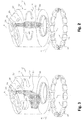
figure 1 est une vue fantôme en perspective d'un cylindre d'un moteur selon l'état de la technique ; - la
figure 2 est une vue fantôme de l'injection de carburant dans un cylindre du moteur de lafigure 1 soumis à un écoulement tourbillonnaire réduit ; - la
figure 3 est une vue fantôme de l'injection de carburant dans un cylindre du moteur de lafigure 1 soumis à un écoulement tourbillonnaire élevé ; - la
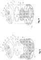
figure 4 est une vue fantôme du cylindre du moteur de lafigure 1 comportant des lumières dont l'angle d'entrée est réduit ; - la
figure 5 est une vue fantôme du cylindre du moteur de lafigure 1 comportant des lumières dont l'angle d'entrée est élevé ; - la
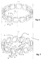
figure 6 est une vue de détail en perspective des lumières d'un cylindre selon un état de la technique ; - la
figure 7 est une vue de détail en perspective des lumières d'un cylindre selon l'invention ; - la
figure 8 est une vue en coupe de la partie haute des lumières selon la ligne 8-8 de lafigure 7 ; - la
figure 9 est une vue en coupe de la partie basse des lumières selon la ligne 9-9 de lafigure 7 ; - la
figure 10 est une vue fantôme de la répartition de l'air d'alimentation dans un cylindre du moteur selon l'invention ; - la
figure 11 est une vue fantôme de l'injection de carburant dans un cylindre du moteur selon l'invention ; - la
figure 12 est une vue fantôme en perspective d'une portion du cylindre d'un moteur avec une lumière vrillée. - la
figure 13 est une vue de coupe du cylindre selon le plan A de lafigure 12 . - la
figure 14 est une vue de coupe du cylindre selon le plan B de lafigure 12 . - Dans la description qui va suivre, des chiffres de référence identiques désignent des pièces identiques ou ayant des fonctions similaires.
- On a représenté à la
figure 1 une partie 10 d'un moteur thermique deux temps de véhicule automobile réalisé conformément à un état de la technique. - De manière connue, la partie 10 du moteur thermique comporte au moins un cylindre axial 12 comportant un alésage 14 qui reçoit en coulissement au moins un piston 16 dont on aperçoit ici une face supérieure 18.
- Le piston 16 délimite avec les parois de l'alésage 14 une chambre de combustion 20 dans le cylindre 12.
- De manière connue, le cylindre 12 comporte une paroi 22 d'extrémité supérieure sensiblement transversale qui reçoit au moins un siège 24 d'une soupape (non représentée), un perçage 26 pour un injecteur (non représenté) et un filetage d'une bougie d'allumage 28.
- Par ailleurs, le cylindre 12 comporte une paroi périphérique 30 dans une partie inférieure 32 de laquelle sont agencées une pluralité de lumières périphériques 34 qui débouchent dans l'alésage 14 et qui sont susceptibles d'être ouvertes ou fermées par le piston 16 en fonction de sa position de montée ou de descente pour permettre ou interdire l'admission d'air dans la chambre de combustion du cylindre 12 au travers desdites lumières 34.
- Chaque lumière 34 est de forme héxaédrique et est délimitée dans la paroi périphérique 30 du cylindre 12 par des faces qui sont conformées sensiblement en quadrilatère.
- Ainsi, les faces comportent au moins une face transversale supérieure 36 et une face transversale inférieure 38 qui s'étendent sensiblement perpendiculairement à la direction axiale "A" de l'alésage 14, et dont des arrêtes radiales correspondantes 40, 42 de la face supérieure 36 et 44, 46 de la face inférieure 38 s'étendent suivant l'épaisseur de la paroi périphérique 30 du cylindre 12, comme représenté à la
figure 6 . - De manière connue, il est possible d'envisager plusieurs conformations des lumières hexaédriques 34.
- Par convention, les lumières hexaédriques 34 sont orientées par rapport à une direction radiale "R" qui s'étend à partir de l'axe "A" du cylindre.
- Comme représenté dans les
figures 6 ,8 et 9 , la direction radiale R s'étend radialement depuis l'axe A du cylindre et traverse la lumière hexaédrique en passant par le centre du débouché de ladite lumière dans l'alésage 14 du cylindre. - En effet, il est conventionnellement admis d'orienter les lumières hexaédriques 34 selon un angle "α" déterminé par rapport à la direction radiale "R" de manière à provoquer, lors de l'admission de l'air au travers desdites fenêtres 34, un mouvement tourbillonnaire aussi connu sous le nom de "Swirl", dont l'intensité dépend de l'angle déterminé. Cet écoulement tourbillonnaire a pour but de chasser les gaz brûlés dans la chambre de combustion 20 en direction des sièges 24 des soupapes afin de permettre l'échappement desdits gaz brûlés.
- Dès lors que le piston 16 est suffisamment remonté et a obturé les lumières périphériques 34, la compression de l'air préalablement admis dans la chambre de combustion 20 commence.
- Simultanément, au cours de cette phase de compression se produit une injection de carburant en provenance de l'injecteur associé au perçage 26, qui permet de constituer un mélange carburé à l'intérieur de la chambre de combustion en mélangeant le carburant injecté à l'air admis.
- L'injection du mélange carburé se produit, par conséquent, dans un flux d'air soumis au mouvement tourbillonnaire ou "Swirl".
- La qualité de l'injection dépend directement de l'intensité du mouvement tourbillonnaire de l'air au sein de la chambre de combustion 20.
- Ainsi, comme l'illustre la
figure 2 , un jet de carburant 50 pulvérisé dans un mouvement tourbillonnaire d'intensité réduite associé à un angle "α" réduit s'étend sensiblement suivant la direction axiale "A" dans une zone centrale de la chambre 20 de combustion. - Au contraire, un jet de carburant 51 pulvérisé dans un mouvement tourbillonnaire d'intensité élevée associé à un angle "α" élevé est sujet généralement à une déviation qui tend à le faire entrer en contact avec les parois périphériques 30, ce qui est préjudiciable à la qualité du mélange carburé.
- En effet, il se produit alors un phénomène de mouillage de la paroi périphérique 30, qui provoque la condensation de gouttelettes de carburant sur les parois 30 de l'alésage 14 et donc une modification des proportions stœchiométriques du mélange qui nuisent à sa bonne inflammation.
- Par ailleurs, l'orientation des lumières 34 influe également directement sur la répartition de l'air frais qui est admis dans la chambre de combustion 20.
- Comme l'illustre la
figure 4 , pour une valeur d'angle "a" réduit, l'admission de l'air au travers des lumières 34 s'effectue sensiblement radialement et il en résulte une formation, à l'intérieur de la chambre 20, d'air sous forme d'un champignon 52. - Au contraire, lorsque l'angle "a" est relativement élevé comme représenté à la
figure 5 , ce qui correspond à un mouvement tourbillonnaire d'intensité élevé, l'air d'admission est réparti sous la forme d'une cuvette 54. - Ainsi, l'angle "a", est plus ou moins important selon l'intensité du mouvement tourbillonnaire que l'on désire créer à l'intérieur de la chambre 20.
- Toutefois, aucune des deux configurations précédemment évoquées ne permet d'obtenir une répartition optimale de l'air d'admission au sein de la chambre 20.
- On remédie à cet inconvénient en proposant des lumières 34 dont l'orientation est variable.
- Les lumières 34 connues de l'état de la technique comportent des arêtes 40, 42, 46, 48 dont l'angle "a" d'orientation est sensiblement identique d'une arête à l'autre.
- On peut caractériser de manière différenciée l'orientation d'une lumière 34 par l'angle que forme la direction d'orientation de la chaque face supérieure 36 ou inférieure 38 avec la direction radiale "R".
- Ainsi, on peut caractériser de manière différenciée l'orientation d'une lumière 34 par l'angle formé entre les arrêtes 40, 42 de la face supérieure 36 ou les arrêtes 46, 48 de la face inférieure 38 avec la direction radiale "R" sur un plan orthogonal à l'axe A du cylindre, comme représenté dans les
figures 8, 9 et12 à 14 . - Le cylindre 12 comporte propose des lumières vrillées 34 dont la direction d'orientation de la face supérieure 36 par rapport à la direction radiale "R" est différente de celle que forme la direction d'orientation de la face inférieure avec la direction radiale "R", pour proposer une lumière 34 vrillée apte à orienter l'air d'admission différemment au fur et à mesure de la remontée du piston 16.
- Ainsi, le cylindre comporte des lumières twistées 34 dont l'orientation est variable, c'est-à-dire des lumières 34 dites vrillées dont des angles "α40", "α42" d'orientation des arrêtes 40, 42 de la face supérieure 36 et des angles "α46", "α48" des arrêtes 46, 48 de la face inférieure 38 sont différents de manière à canaliser différemment l'air d'admission lors de l'admission, le piston 16 du moteur obturant progressivement lors de sa remontée lesdites lumières 34 et favorisant ainsi la répartition de l'air d'admission et son orientation de manière différenciée en fonction de la partie de la lumière 34 traversée par le flux d'air.
- Dans un moteur du type décrit précédemment, le cylindre dans lequel coulisse le piston comporte des lumières twistées dont la direction d'orientation de la face supérieure 36 forme avec la direction radiale "R" un angle α40,α42 qui est orienté selon un premier sens déterminé, et en ce que la direction d'orientation de la face inférieure 38 forme avec la direction radiale "R" un angle α46,α48 qui est orienté selon un second sens déterminé opposé au premier sens déterminé, pour proposer une lumière 34 vrillée apte à orienter l'air d'admission différemment au fur et à mesure de la remontée du piston 16, afin d'homogénéiser le mélange.
- Ladite lumière vrillée comporte une surface supérieure en regard avec une surface inférieure et des surfaces latérales de jonction disposées l'une en regard de l'autre entre la surface supérieure et la surface inférieure. Elle débouche dans l'alésage 14 par un débouché 70 qui comporte une arête supérieure 71 et une arête inférieure 73 associée respectivement aux faces supérieure 36 et inférieure 38 et des arêtes latérales 72 gauche et droite de jonction associées auxdites surfaces latérales de jonction entre la surface supérieure et la surface inférieure de la lumière. On distingue les arêtes latérales 72 gauche et droite par rapport à un axe médian du débouché 70 joignant les centres des arêtes supérieure 71 et inférieure 73. Les arêtes latérales 72 gauche et droite peuvent alors être sensiblement inclinées par rapport à la direction de coulissement parallèle à l'axe A du cylindre.
- Le piston est animé par un mouvement de coulissement selon l'axe A du cylindre. Il sépare l'alésage 14 en une partie supérieure où se produit la combustion du mélange de gaz et de carburant et une partie inférieure. Il est entouré par au moins un segment d'étanchéité (non représenté) destiné à assurer l'étancheité entre la partie supérieure et la partie inférieure de l'alésage, ou de raclage destiné à enlever l'huile projetée pour assurer la lubrification sur la paroi intérieure de l'alésage.
- Ainsi, quand le piston descend, le segment d'étanchéité en contact avec la paroi 30 de l'alésage 14 du cylindre peut se présenter devant au moins une lumière vrillée 34. Il vient alors appuyer sur les arêtes supérieure 71, inférieure 73 et latérales 72 gauche et droite du débouché 70 de ladite lumière vrillée. L'arête gauche est susceptible de venir appuyer par réaction sur le segment. Le piston descendant, ledit appui se déplace sur le segment qui lui reste fixe en rotation. L'arête gauche vient alors usiner ou éroder le segment. Lorsque le piston remonte, le phénomène se reproduit avec l'arête droite. Ainsi les segments sont fortement affectés par le débouché des lumières vers l'intérieur du cylindre.
- Afin de réduire cet effet d'usinage, selon l'invention, chacune desdites lumières 34 vrillées présente un débouché 70 dans l'alésage 14 du cylindre qui comporte au moins une arête latérale 72 sensiblement parallèle à l'axe de coulissement du piston. Ladite lumière vrillée 34 avec des arêtes latérales droite est représentée en
figures 12 à 14 . Autrement dit, les arêtes 40, 42 d'orientation de gaz de la face supérieure 36 forment avec la direction radiale des angles "α40", "α42" qui sont orientés selon un premier sens déterminé et qui sont chacun compris dans une première plage angulaire déterminée et les arêtes 46, 48 de la face inférieure 38 forment avec la direction radiale "R" des angles "α46", "α48" qui sont orientés selon un second sens déterminé opposé au premier sens déterminé et qui chacun sont compris dans une seconde plage angulaire déterminée pour proposer une lumière 34 vrillée apte à orienter l'air d'admission différemment au fur et à mesure de la remontée du piston 16. - Cette configuration a été représentée en particulier aux
figures 7 à 9 . - Sur les
figures 7 à 9 , on a affecté les références "α40" et "α42" aux angles formés entre les arêtes respectives 40 et 42 de la face supérieure 36 de la lumière 34 et la direction radiale "R", et les références "α46, α48" aux angles formés entre les arrêtes 46 et 48 de la face inférieure 38 de la lumière 34 et la direction radiale "R". - Dans cette configuration, les angles "α40, α42" sont, par conséquent, conformément à l'invention, orientés selon un premier sens déterminé, ici par exemple le sens horaire, comme représenté à la
figure 8 , tandis que les angles "α46", "α48" des arrêtes respectives 46 et 48 de la face inférieure 38 de la lumière 34 sont orientés suivant le sens anti-horaire, comme représenté à lafigure 9 . - De façon préférentielle, l'angle α40,α42 selon le premier sens d'orientation est compris dans une première plage angulaire déterminée entre 25 et 45 degrés dans un premier sens déterminé.
- Par ailleurs, les angles α46,α48 selon le second sens d'orientation sont compris dans une plage angulaire déterminée entre 10 à 35 degrés dans le second sens déterminé opposé au premier sens déterminé.
- Ainsi la première plage angulaire associée aux angles d'orientation "α40, α42" des arêtes 40 et 42 de la face supérieure 36 de la lumière 34 est comprise entre les valeurs de 25 et 45° par rapport à la direction radiale "R" dans le premier sens déterminé.
- La seconde plage angulaire associée aux angles d'orientation "α46", "α48" des arrêtes 46 et 48 de la face inférieure 38 de la lumière 34 est comprise entre les valeurs angulaires de 10 et 35° par rapport à la direction radiale "R" dans le sens anti-horaire opposé au premier sens déterminé.
- Cette configuration permet, comme l'illustre la
figure 10 , de proposer une répartition 56 de l'air d'admission qui est sensiblement uniforme puisqu'elle résulte d'une orientation de l'air au travers des lumières 34 qui varie progressivement au fur et à mesure de la descente puis de la remontée du piston 16 et de l'obturation des lumières 34. - En effet, lorsque le piston 16 descend, il canalise en premier lieu l'air au travers de l'intégralité des lumières 34 et il n'obture que peu ou pas lesdites lumières 34. L'air admis est donc orienté sensiblement par les quatre arrêtes 46, 48 de la face inférieure 38 et 40, 42 de la face supérieure 36.
- Puis, lorsque le piston 16 remonte, la partie inférieure de chaque lumière 34 est obturée et l'air n'est quasiment plus orienté que par les arrêtes 40, 42 de la face supérieure 36 de la lumière 34 qui sont plus fortement inclinées que les arêtes inférieures 46, 48 de la face inférieure 38 de la lumière 34.
- Le résultat est sensiblement la combinaison de deux mouvements tourbillonnaires, un mouvement tourbillonnaire réduit puisque provoqué par une admission pratiquement radiale, et un mouvement tourbillonnaire élevé puisque produit par une orientation sensiblement tangentielle.
- La répartition 56 de l'air est donc parfaitement uniforme dans la chambre 20 de combustion.
- Selon la
figure 12 , la lumière 34 présente un débouché 70 dans l'alésage 14 entouré par des bords 75 comprenant deux arêtes latérales 72 de jointure entre la face supérieure 38 et la face inférieure 36, sensiblement parallèles entre elles et une arête supérieure et une arête inférieure. - Lesdites arêtes latérales de jointure sont sensiblement parallèles à l'axe A de coulissement du piston identique à l'axe du cylindre.
- L'arête supérieure 71 présente ainsi un arc de cercle sensiblement égal à l'arc de cercle de l'arête inférieure 73.
- Le segment passe devant la lumière 34 et l'arête latérale va appuyer par réaction sur le segment. L'arête latérale 62 étant parallèle à l'axe de coulissement du piston, l'appui reste sensiblement à la même position relative par rapport au segment et ne vient donc pas usiner ou éroder le segment. Lorsque le piston descend ou remonte, le phénomène est identique avec l'autre arête latérale 72 voisine de laditelumière 34.
- Le segment n'est donc pas suceptible d'être usiné ou érodé par le passage devant la lumière vrillée lors du coulissement en va-et-vient du piston dans l'alésage 14 du cylindre.
- Le segment vient également appuyer sur les arêtes supérieure et inférieure sur un déplacement relativement court correspondant à la dénivellation selon l'axe de coulissement de chacune des surfaces supérieure 36 et inférieure 38.
- Ainsi, comme l'illustre la
figure 11 , un jet 59 de carburant effectué dans ces conditions au sein de la chambre 20 de combustion s'étend suivant la direction axiale de manière uniforme mais plus amplement dans la chambre 20 que le jet de carburant 50 effectué dans un mouvement tourbillonnaire réduit qui a été représenté précédemment en référence à lafigure 2 . Le jet 59 de carburant ne présente pas non plus les irrégularités de répartition du mélange carburé 51 injecté dans un mouvement tourbillonnaire élevé comme précédemment représenté à lafigure 3 . - Dans le mode de réalisation préféré de l'invention qui a été représenté à la
figure 7 , les faces supérieure 36 et inférieure 38 sont sensiblement planes. - La face supérieure 36 et ou la face inférieure 38 peut être est légèrement inclinée par rapport à un plan orthogonal à l'axe A du cylindre 12 d'un angle (non représenté) inférieur à 10°.
- Le débouché 70 peut présenter une forme sensiblement quadrilatérale formée par les arêtes supérieure 71 et inférieure 73 desdites faces supérieure 36 et inférieure 38 planes et les arêtes latérales 72 .
- Selon un autre mode de réalisation, ladite forme peut être rectangulaire voire carrée lorsque la face supérieure 36 est parallèle à la face inférieure 38.
- Cette configuration n'est pas limitative de l'invention. En variante (non représentée) la face supérieure 36 est concave et tournée vers la face inférieure 38. De même, la face inférieure peut être convexe et tournée vers la face supérieure.
- Le débouché 70 de la lumière vrillée 34 dans l'alésage 14 présente alors sensiblement une forme sensiblement oblongue étirée selon l'axe de coulissement du psiton et comportant des arêtes latérales 72 parallèles avec ledit axe de coulissement.
- De façon avantageuse, l'angle d'orientation "α40, α42" d'au moins une arrête 40, 42 de la face supérieure 36 de la lumière 34 et l'angle "α46, α48" d'orientation de l'arrête 46, 48 en regard de la face inférieure 38 associée forme de préférence un écart angulaire minimal déterminé qui est propre à conformer des faces latérales sensiblement verticales 58, 60 de la lumière 34, qui sont déterminées par lesdites arrêtes 40, 46, d'une part et, 42, 48, d'autre part, comme représenté à la
figure 7 , selon une portion de conduit divergent orientée vers l'intérieur du cylindre. Cette configuration permet de favoriser la diffusion de l'air à l'intérieur de la chambre 20 de combustion. - Ainsi, le choix d'un écart angulaire minimal déterminé entre les angles d'orientation "α40" et "α46" de deux arrêtes superposées 40, 46 et/ou entre les angles d'orientation "α42", "α48" de deux arrêtes superposées 42, 48 permettent de conformer au moins une face latérale verticale 58 et ou une face latéral verticale 60 sous la forme d'une portion de conduit divergent orientée vers l'intérieur du cylindre 14, ce qui permet d'améliorer la diffusion de l'air à l'intérieur de la chambre 20 de combustion.
- Le niveau d'air frais qui monte permet de ne plus piéger les gaz brulés qui sont de ce fait entrainés vers les soupapes. L'évacuation des gaz brulés est donc faite automatiquement.
- Il sera compris que chaque face latérale verticale 58, 60 s'étendant sensiblement selon l'axe A du cylindre 12 rejoint donc la face supérieure 36 et la face inférieure 38. A cet effet, les faces supérieure et inférieure 36, 38 sont chacune jointes aux faces latérales par des congés 59. Le rayon d'un tel congé 59 est compris entre 1mm et 3mm.
- Le meilleur dimensionnement des lumières 34 sera obtenu avec une distance entre la face inférieure 38 et la face supérieure 36 comprise entre 5 et 20% de la course du piston 16.
- De façon préférentielle, le nombre de lumières peut varier de 8 à 30 pour des diamètres de cylindres variant jusqu'à 75mm, la hauteur desdites lumières étant comprise entre 5 et 12 mm.
- L'invention permet donc de favoriser avantageusement le remplissage en gaz frais et l'évacuation des gaz brulés d'un moteur de type deux temps comportant des lumières 34 périphériques tout en améliorant la fiabilité dudit moteur.
Claims (7)
- Moteur thermique deux temps de véhicule automobile, comportant au moins un cylindre axial (12) comportant un alésage (14) qui reçoit en coulissement un piston (16),
ledit cylindre (12) comportant une paroi périphérique (30) qui comporte une partie inférieure (32) dans laquelle sont agencées une pluralité de lumières périphériques (34), qui débouchent dans l'alésage (14) et sont aptes à être ouvertes ou fermées par le piston (16) entouré par au moins un segment, en mouvement pour permettre ou interdire l'admission d'air dans le cylindre (12),
chaque lumière (34) étant orientée par une direction radiale (R) s'étendant radialement depuis l'axe (A) du cylindre et passant par le centre du débouché (70) de chaque lumière dans l'alésage, et délimitée dans la paroi périphérique (30) par une face supérieure (36) et une face inférieure (38) en vis-à-vis délimitées par des arêtes radiales (40, 42, 46, 48) s'étendant selon des directions d'orientation sensiblement orthogonales à la direction axiale (A) du cylindre (12) caractérisé en ce que
la direction d'orientation des arêtes radiales de la face supérieure (36), forme avec la direction radiale (R) sur un plan orthogonal à la direction axiale (A) du cylindre, un angle (040,042) qui est orienté selon un premier sens déterminé, et la direction d'orientation des arêtes radiales de la face inférieure (38) forme avec la direction radiale (R) sur ledit plan orthogonal à la direction axiale (A) du cylindre, un angle (α46,α48) qui est orienté selon un second sens déterminé opposé au premier sens déterminé, chaque lumière (34) vrillée dirigeant l'air d'admission selon deux orientations en sens contraire entrainant un mouvement tourbillonnaire réduit provoqué par une admission pratiquement radiale quand le piston n'obture pas chaque lumière, et selon une orientation sensiblement tangentielle selon le premier sens déterminé entrainant un mouvement tourbillonnaire élevé au fur et à mesure de la remontée du piston (16), le débouché (70) de chaque lumière (34) dans l'alésage (14), entouré par des bords (75) comprenant au moins une arête latérale de jointure (72) entre la face supérieure (36) et la face inférieure (38) parallèle à l'axe (A) du cylindre. - Moteur thermique selon la revendication 1, caratérisé en ce que le débouché (70) de chaque lumière dans l'alésage est sensiblement parallélépipédique.
- Moteur thermique selon l'une quelconque des revendications 1 ou 2, caractérisé en ce que le débouché (70) de chaque lumière (34) dans l'alésage (14) est sensiblement quadrilatéral présentant deux arêtes orthogonales deux à deux.
- Moteur thermique selon l'une quelconque des revendications 1 ou 2, caratérisé en ce que le débouché (70) de chaque lumière (34) dans l'alésage (14) est sensiblement oblong.
- Moteur thermique selon l'une quelconque des revendications 1 à 4, caractérisé en ce que la direction d'orientation de la face supérieure forme avec la direction radiale (R) angle (α40,α42) compris dans une première plage angulaire déterminée entre 25 et 45° et orienté selon premier sens déterminé.
- Moteur thermique selon la revendication 5, caractérisé en ce que la direction d'orientation de la face inférieure forme avec la direction radiale l' angle (α46,α48) compris dans une seconde plage angulaire déterminée entre 10 à 35 degrés dans le second sens déterminé opposé au premier sens déterminé.
- Moteur thermique selon l'une quelconque des revendications 1 à 6, caractérisé en ce que la distance entre la face inférieure et la face supérieure est comprise entre 5 et 20% de la course du piston.
Applications Claiming Priority (2)
| Application Number | Priority Date | Filing Date | Title |
|---|---|---|---|
| FR1457495A FR3020657A1 (fr) | 2014-05-05 | 2014-08-01 | Moteur thermique deux temps de vehicule automobile a lumieres d'admission vrillees avec des aretes laterales droites |
| PCT/FR2015/050829 WO2016016522A1 (fr) | 2014-08-01 | 2015-03-31 | Moteur thermique deux temps de véhicule automobile a lumières d'admission vrillées avec des arêtes latérales droites |
Publications (2)
| Publication Number | Publication Date |
|---|---|
| EP3175100A1 EP3175100A1 (fr) | 2017-06-07 |
| EP3175100B1 true EP3175100B1 (fr) | 2020-08-26 |
Family
ID=52991873
Family Applications (1)
| Application Number | Title | Priority Date | Filing Date |
|---|---|---|---|
| EP15717579.5A Active EP3175100B1 (fr) | 2014-08-01 | 2015-03-31 | Moteur thermique deux temps de véhicule automobile à lumières d'admission vrillées avec des arêtes latérales droites |
Country Status (2)
| Country | Link |
|---|---|
| EP (1) | EP3175100B1 (fr) |
| WO (1) | WO2016016522A1 (fr) |
Family Cites Families (3)
| Publication number | Priority date | Publication date | Assignee | Title |
|---|---|---|---|---|
| GB778589A (en) * | 1956-01-16 | 1957-07-10 | Texaco Development Corp | A two-stroke cycle uniflow-scavenged internal combustion engine having air induction port means |
| KR840007136A (ko) * | 1982-11-04 | 1984-12-05 | 오다 테이시로오 | 단류 2사이클엔진의 실린더라이너 |
| GB2490397A (en) * | 2011-04-25 | 2012-10-31 | Ecomotors Internat Inc | Cylinder having a first plurality of intake ports and a second plurality of intake ports at respective first and second distances from a crankshaft |
-
2015
- 2015-03-31 EP EP15717579.5A patent/EP3175100B1/fr active Active
- 2015-03-31 WO PCT/FR2015/050829 patent/WO2016016522A1/fr not_active Ceased
Non-Patent Citations (1)
| Title |
|---|
| None * |
Also Published As
| Publication number | Publication date |
|---|---|
| EP3175100A1 (fr) | 2017-06-07 |
| WO2016016522A1 (fr) | 2016-02-04 |
Similar Documents
| Publication | Publication Date | Title |
|---|---|---|
| WO1999053179A1 (fr) | Moteur a combustion interne a allumage commande et a injection directe | |
| EP1944476B1 (fr) | Siège de soupape usiné en deux chanfreins désaxés | |
| FR3020657A1 (fr) | Moteur thermique deux temps de vehicule automobile a lumieres d'admission vrillees avec des aretes laterales droites | |
| WO2009062978A1 (fr) | Culasse d'un moteur a combustion interne | |
| WO2016016522A1 (fr) | Moteur thermique deux temps de véhicule automobile a lumières d'admission vrillées avec des arêtes latérales droites | |
| EP0997622A1 (fr) | Moteur à combustion interne à allumage commandé et à injection directe comportant un piston perfectionné | |
| EP1215377B1 (fr) | Système d'admission de gaz dans une chambre de combustion dont le conduit d'admission comporte une nervure | |
| FR2924165A3 (fr) | Culasse de moteur a combustion interne dont les conduits d'admission presentent un meplat generateur de tourbillons axiaux | |
| EP0921287B1 (fr) | Moteur à combustion interne à allumage commandé et à injection directe | |
| EP1002941B1 (fr) | Moteur à combustion interne à allumage commandé et à injection directe | |
| EP1944477B1 (fr) | Siège de soupape usiné en plusieurs chanfreins | |
| EP1591642A1 (fr) | Circuit d'admission comportant un orifice muni d'une entaille pour conférer un mouvement tourbillonnaire aux gaz admis | |
| FR3057913B1 (fr) | Piston pour moteur a combustion interne a rideau aerodynamique | |
| EP1316710A1 (fr) | Piston pour moteur à combustion interne et moteur associé | |
| FR2713282A1 (fr) | Moteur à allumage par compression à injection directe, à combustion améliorée. | |
| EP1596050A1 (fr) | Moteur à combustion muni d'un piston concave cooperant avec une surface de chasse convexe de la culasse | |
| EP1219798A2 (fr) | Système d'admission de gaz d'un moteur à combustion | |
| FR3103515A1 (fr) | Siege de soupape d’echappement presentant un profil aerodynamique optimise | |
| EP1219797A1 (fr) | Système d'admission de gaz dans une chambre à combustion comportant des moyens de déflection | |
| FR2869951A1 (fr) | Chambre de combustion pour moteur a combustion interne a injection directe | |
| FR2770875A1 (fr) | Moteur a combustion interne a allumage commande, a injection directe et a bougie decalee | |
| FR2590936A1 (fr) | Moteur a combustion interne | |
| FR2772074A1 (fr) | Moteur a combustion interne a allumage commande et a injection directe | |
| FR2890120A3 (fr) | Culasse de moteur a combustion interne comprenant une tete de cylindre adaptee a reduire les perturbations entre des flux de gaz dans le cylindre | |
| FR2928971A1 (fr) | Dispositif d'admission d'air dans un cylindre d'un moteur a combustion interne |
Legal Events
| Date | Code | Title | Description |
|---|---|---|---|
| STAA | Information on the status of an ep patent application or granted ep patent |
Free format text: STATUS: THE INTERNATIONAL PUBLICATION HAS BEEN MADE |
|
| 17P | Request for examination filed |
Effective date: 20170207 |
|
| AK | Designated contracting states |
Kind code of ref document: A1 Designated state(s): AL AT BE BG CH CY CZ DE DK EE ES FI FR GB GR HR HU IE IS IT LI LT LU LV MC MK MT NL NO PL PT RO RS SE SI SK SM TR |
|
| AX | Request for extension of the european patent |
Extension state: BA ME |
|
| PUAI | Public reference made under article 153(3) epc to a published international application that has entered the european phase |
Free format text: ORIGINAL CODE: 0009012 |
|
| STAA | Information on the status of an ep patent application or granted ep patent |
Free format text: STATUS: REQUEST FOR EXAMINATION WAS MADE |
|
| DAV | Request for validation of the european patent (deleted) | ||
| DAX | Request for extension of the european patent (deleted) | ||
| STAA | Information on the status of an ep patent application or granted ep patent |
Free format text: STATUS: EXAMINATION IS IN PROGRESS |
|
| 17Q | First examination report despatched |
Effective date: 20171220 |
|
| 17Q | First examination report despatched |
Effective date: 20180116 |
|
| GRAP | Despatch of communication of intention to grant a patent |
Free format text: ORIGINAL CODE: EPIDOSNIGR1 |
|
| STAA | Information on the status of an ep patent application or granted ep patent |
Free format text: STATUS: GRANT OF PATENT IS INTENDED |
|
| INTG | Intention to grant announced |
Effective date: 20200325 |
|
| GRAS | Grant fee paid |
Free format text: ORIGINAL CODE: EPIDOSNIGR3 |
|
| GRAA | (expected) grant |
Free format text: ORIGINAL CODE: 0009210 |
|
| STAA | Information on the status of an ep patent application or granted ep patent |
Free format text: STATUS: THE PATENT HAS BEEN GRANTED |
|
| AK | Designated contracting states |
Kind code of ref document: B1 Designated state(s): AL AT BE BG CH CY CZ DE DK EE ES FI FR GB GR HR HU IE IS IT LI LT LU LV MC MK MT NL NO PL PT RO RS SE SI SK SM TR |
|
| REG | Reference to a national code |
Ref country code: GB Ref legal event code: FG4D Free format text: NOT ENGLISH |
|
| REG | Reference to a national code |
Ref country code: CH Ref legal event code: EP |
|
| REG | Reference to a national code |
Ref country code: DE Ref legal event code: R096 Ref document number: 602015057993 Country of ref document: DE |
|
| REG | Reference to a national code |
Ref country code: AT Ref legal event code: REF Ref document number: 1306579 Country of ref document: AT Kind code of ref document: T Effective date: 20200915 |
|
| REG | Reference to a national code |
Ref country code: IE Ref legal event code: FG4D Free format text: LANGUAGE OF EP DOCUMENT: FRENCH |
|
| REG | Reference to a national code |
Ref country code: LT Ref legal event code: MG4D |
|
| PG25 | Lapsed in a contracting state [announced via postgrant information from national office to epo] |
Ref country code: FI Free format text: LAPSE BECAUSE OF FAILURE TO SUBMIT A TRANSLATION OF THE DESCRIPTION OR TO PAY THE FEE WITHIN THE PRESCRIBED TIME-LIMIT Effective date: 20200826 Ref country code: PT Free format text: LAPSE BECAUSE OF FAILURE TO SUBMIT A TRANSLATION OF THE DESCRIPTION OR TO PAY THE FEE WITHIN THE PRESCRIBED TIME-LIMIT Effective date: 20201228 Ref country code: SE Free format text: LAPSE BECAUSE OF FAILURE TO SUBMIT A TRANSLATION OF THE DESCRIPTION OR TO PAY THE FEE WITHIN THE PRESCRIBED TIME-LIMIT Effective date: 20200826 Ref country code: LT Free format text: LAPSE BECAUSE OF FAILURE TO SUBMIT A TRANSLATION OF THE DESCRIPTION OR TO PAY THE FEE WITHIN THE PRESCRIBED TIME-LIMIT Effective date: 20200826 Ref country code: HR Free format text: LAPSE BECAUSE OF FAILURE TO SUBMIT A TRANSLATION OF THE DESCRIPTION OR TO PAY THE FEE WITHIN THE PRESCRIBED TIME-LIMIT Effective date: 20200826 Ref country code: NO Free format text: LAPSE BECAUSE OF FAILURE TO SUBMIT A TRANSLATION OF THE DESCRIPTION OR TO PAY THE FEE WITHIN THE PRESCRIBED TIME-LIMIT Effective date: 20201126 Ref country code: GR Free format text: LAPSE BECAUSE OF FAILURE TO SUBMIT A TRANSLATION OF THE DESCRIPTION OR TO PAY THE FEE WITHIN THE PRESCRIBED TIME-LIMIT Effective date: 20201127 Ref country code: BG Free format text: LAPSE BECAUSE OF FAILURE TO SUBMIT A TRANSLATION OF THE DESCRIPTION OR TO PAY THE FEE WITHIN THE PRESCRIBED TIME-LIMIT Effective date: 20201126 |
|
| REG | Reference to a national code |
Ref country code: NL Ref legal event code: MP Effective date: 20200826 |
|
| REG | Reference to a national code |
Ref country code: AT Ref legal event code: MK05 Ref document number: 1306579 Country of ref document: AT Kind code of ref document: T Effective date: 20200826 |
|
| PG25 | Lapsed in a contracting state [announced via postgrant information from national office to epo] |
Ref country code: NL Free format text: LAPSE BECAUSE OF FAILURE TO SUBMIT A TRANSLATION OF THE DESCRIPTION OR TO PAY THE FEE WITHIN THE PRESCRIBED TIME-LIMIT Effective date: 20200826 Ref country code: RS Free format text: LAPSE BECAUSE OF FAILURE TO SUBMIT A TRANSLATION OF THE DESCRIPTION OR TO PAY THE FEE WITHIN THE PRESCRIBED TIME-LIMIT Effective date: 20200826 Ref country code: LV Free format text: LAPSE BECAUSE OF FAILURE TO SUBMIT A TRANSLATION OF THE DESCRIPTION OR TO PAY THE FEE WITHIN THE PRESCRIBED TIME-LIMIT Effective date: 20200826 Ref country code: PL Free format text: LAPSE BECAUSE OF FAILURE TO SUBMIT A TRANSLATION OF THE DESCRIPTION OR TO PAY THE FEE WITHIN THE PRESCRIBED TIME-LIMIT Effective date: 20200826 Ref country code: IS Free format text: LAPSE BECAUSE OF FAILURE TO SUBMIT A TRANSLATION OF THE DESCRIPTION OR TO PAY THE FEE WITHIN THE PRESCRIBED TIME-LIMIT Effective date: 20201226 |
|
| PG25 | Lapsed in a contracting state [announced via postgrant information from national office to epo] |
Ref country code: CZ Free format text: LAPSE BECAUSE OF FAILURE TO SUBMIT A TRANSLATION OF THE DESCRIPTION OR TO PAY THE FEE WITHIN THE PRESCRIBED TIME-LIMIT Effective date: 20200826 Ref country code: DK Free format text: LAPSE BECAUSE OF FAILURE TO SUBMIT A TRANSLATION OF THE DESCRIPTION OR TO PAY THE FEE WITHIN THE PRESCRIBED TIME-LIMIT Effective date: 20200826 Ref country code: SM Free format text: LAPSE BECAUSE OF FAILURE TO SUBMIT A TRANSLATION OF THE DESCRIPTION OR TO PAY THE FEE WITHIN THE PRESCRIBED TIME-LIMIT Effective date: 20200826 Ref country code: RO Free format text: LAPSE BECAUSE OF FAILURE TO SUBMIT A TRANSLATION OF THE DESCRIPTION OR TO PAY THE FEE WITHIN THE PRESCRIBED TIME-LIMIT Effective date: 20200826 Ref country code: EE Free format text: LAPSE BECAUSE OF FAILURE TO SUBMIT A TRANSLATION OF THE DESCRIPTION OR TO PAY THE FEE WITHIN THE PRESCRIBED TIME-LIMIT Effective date: 20200826 |
|
| REG | Reference to a national code |
Ref country code: DE Ref legal event code: R097 Ref document number: 602015057993 Country of ref document: DE |
|
| PG25 | Lapsed in a contracting state [announced via postgrant information from national office to epo] |
Ref country code: ES Free format text: LAPSE BECAUSE OF FAILURE TO SUBMIT A TRANSLATION OF THE DESCRIPTION OR TO PAY THE FEE WITHIN THE PRESCRIBED TIME-LIMIT Effective date: 20200826 Ref country code: AT Free format text: LAPSE BECAUSE OF FAILURE TO SUBMIT A TRANSLATION OF THE DESCRIPTION OR TO PAY THE FEE WITHIN THE PRESCRIBED TIME-LIMIT Effective date: 20200826 Ref country code: AL Free format text: LAPSE BECAUSE OF FAILURE TO SUBMIT A TRANSLATION OF THE DESCRIPTION OR TO PAY THE FEE WITHIN THE PRESCRIBED TIME-LIMIT Effective date: 20200826 |
|
| PG25 | Lapsed in a contracting state [announced via postgrant information from national office to epo] |
Ref country code: SK Free format text: LAPSE BECAUSE OF FAILURE TO SUBMIT A TRANSLATION OF THE DESCRIPTION OR TO PAY THE FEE WITHIN THE PRESCRIBED TIME-LIMIT Effective date: 20200826 |
|
| PLBE | No opposition filed within time limit |
Free format text: ORIGINAL CODE: 0009261 |
|
| STAA | Information on the status of an ep patent application or granted ep patent |
Free format text: STATUS: NO OPPOSITION FILED WITHIN TIME LIMIT |
|
| PG25 | Lapsed in a contracting state [announced via postgrant information from national office to epo] |
Ref country code: IT Free format text: LAPSE BECAUSE OF FAILURE TO SUBMIT A TRANSLATION OF THE DESCRIPTION OR TO PAY THE FEE WITHIN THE PRESCRIBED TIME-LIMIT Effective date: 20200826 |
|
| 26N | No opposition filed |
Effective date: 20210527 |
|
| PG25 | Lapsed in a contracting state [announced via postgrant information from national office to epo] |
Ref country code: SI Free format text: LAPSE BECAUSE OF FAILURE TO SUBMIT A TRANSLATION OF THE DESCRIPTION OR TO PAY THE FEE WITHIN THE PRESCRIBED TIME-LIMIT Effective date: 20200826 |
|
| PG25 | Lapsed in a contracting state [announced via postgrant information from national office to epo] |
Ref country code: MC Free format text: LAPSE BECAUSE OF FAILURE TO SUBMIT A TRANSLATION OF THE DESCRIPTION OR TO PAY THE FEE WITHIN THE PRESCRIBED TIME-LIMIT Effective date: 20200826 |
|
| REG | Reference to a national code |
Ref country code: CH Ref legal event code: PL |
|
| REG | Reference to a national code |
Ref country code: BE Ref legal event code: MM Effective date: 20210331 |
|
| PG25 | Lapsed in a contracting state [announced via postgrant information from national office to epo] |
Ref country code: LU Free format text: LAPSE BECAUSE OF NON-PAYMENT OF DUE FEES Effective date: 20210331 Ref country code: LI Free format text: LAPSE BECAUSE OF NON-PAYMENT OF DUE FEES Effective date: 20210331 Ref country code: CH Free format text: LAPSE BECAUSE OF NON-PAYMENT OF DUE FEES Effective date: 20210331 Ref country code: IE Free format text: LAPSE BECAUSE OF NON-PAYMENT OF DUE FEES Effective date: 20210331 |
|
| PG25 | Lapsed in a contracting state [announced via postgrant information from national office to epo] |
Ref country code: BE Free format text: LAPSE BECAUSE OF NON-PAYMENT OF DUE FEES Effective date: 20210331 |
|
| PG25 | Lapsed in a contracting state [announced via postgrant information from national office to epo] |
Ref country code: HU Free format text: LAPSE BECAUSE OF FAILURE TO SUBMIT A TRANSLATION OF THE DESCRIPTION OR TO PAY THE FEE WITHIN THE PRESCRIBED TIME-LIMIT; INVALID AB INITIO Effective date: 20150331 |
|
| PG25 | Lapsed in a contracting state [announced via postgrant information from national office to epo] |
Ref country code: CY Free format text: LAPSE BECAUSE OF FAILURE TO SUBMIT A TRANSLATION OF THE DESCRIPTION OR TO PAY THE FEE WITHIN THE PRESCRIBED TIME-LIMIT Effective date: 20200826 |
|
| P01 | Opt-out of the competence of the unified patent court (upc) registered |
Effective date: 20230608 |
|
| REG | Reference to a national code |
Ref country code: GB Ref legal event code: 732E Free format text: REGISTERED BETWEEN 20231228 AND 20240103 |
|
| PG25 | Lapsed in a contracting state [announced via postgrant information from national office to epo] |
Ref country code: MK Free format text: LAPSE BECAUSE OF FAILURE TO SUBMIT A TRANSLATION OF THE DESCRIPTION OR TO PAY THE FEE WITHIN THE PRESCRIBED TIME-LIMIT Effective date: 20200826 |
|
| REG | Reference to a national code |
Ref country code: DE Ref legal event code: R081 Ref document number: 602015057993 Country of ref document: DE Owner name: NEW H POWERTRAIN HOLDING, S.L.U., ES Free format text: FORMER OWNER: RENAULT S.A.S., BOULOGNE BILLANCOURT, FR |
|
| PG25 | Lapsed in a contracting state [announced via postgrant information from national office to epo] |
Ref country code: TR Free format text: LAPSE BECAUSE OF FAILURE TO SUBMIT A TRANSLATION OF THE DESCRIPTION OR TO PAY THE FEE WITHIN THE PRESCRIBED TIME-LIMIT Effective date: 20200826 |
|
| PG25 | Lapsed in a contracting state [announced via postgrant information from national office to epo] |
Ref country code: MT Free format text: LAPSE BECAUSE OF FAILURE TO SUBMIT A TRANSLATION OF THE DESCRIPTION OR TO PAY THE FEE WITHIN THE PRESCRIBED TIME-LIMIT Effective date: 20200826 |
|
| PGFP | Annual fee paid to national office [announced via postgrant information from national office to epo] |
Ref country code: GB Payment date: 20260324 Year of fee payment: 12 |
|
| PGFP | Annual fee paid to national office [announced via postgrant information from national office to epo] |
Ref country code: DE Payment date: 20260319 Year of fee payment: 12 |
|
| PGFP | Annual fee paid to national office [announced via postgrant information from national office to epo] |
Ref country code: FR Payment date: 20260320 Year of fee payment: 12 |