EP3175283B1 - Modulare brille - Google Patents
Modulare brille Download PDFInfo
- Publication number
- EP3175283B1 EP3175283B1 EP15754271.3A EP15754271A EP3175283B1 EP 3175283 B1 EP3175283 B1 EP 3175283B1 EP 15754271 A EP15754271 A EP 15754271A EP 3175283 B1 EP3175283 B1 EP 3175283B1
- Authority
- EP
- European Patent Office
- Prior art keywords
- semi
- pair
- contour
- spectacles
- longitudinal
- Prior art date
- Legal status (The legal status is an assumption and is not a legal conclusion. Google has not performed a legal analysis and makes no representation as to the accuracy of the status listed.)
- Not-in-force
Links
- 239000003086 colorant Substances 0.000 claims description 4
- 238000013519 translation Methods 0.000 claims description 4
- 238000005520 cutting process Methods 0.000 claims description 3
- 238000003860 storage Methods 0.000 claims description 3
- 238000003825 pressing Methods 0.000 claims description 2
- 230000001419 dependent effect Effects 0.000 claims 1
- 238000000926 separation method Methods 0.000 claims 1
- 239000011521 glass Substances 0.000 description 40
- 210000000078 claw Anatomy 0.000 description 15
- 238000013461 design Methods 0.000 description 15
- 230000000295 complement effect Effects 0.000 description 8
- 241001639412 Verres Species 0.000 description 5
- 238000003780 insertion Methods 0.000 description 3
- 230000037431 insertion Effects 0.000 description 3
- 239000000463 material Substances 0.000 description 3
- 238000007373 indentation Methods 0.000 description 2
- QTBSBXVTEAMEQO-UHFFFAOYSA-M Acetate Chemical compound CC([O-])=O QTBSBXVTEAMEQO-UHFFFAOYSA-M 0.000 description 1
- 239000004677 Nylon Substances 0.000 description 1
- WYTGDNHDOZPMIW-RCBQFDQVSA-N alstonine Natural products C1=CC2=C3C=CC=CC3=NC2=C2N1C[C@H]1[C@H](C)OC=C(C(=O)OC)[C@H]1C2 WYTGDNHDOZPMIW-RCBQFDQVSA-N 0.000 description 1
- 230000000712 assembly Effects 0.000 description 1
- 238000000429 assembly Methods 0.000 description 1
- 230000000903 blocking effect Effects 0.000 description 1
- 238000007596 consolidation process Methods 0.000 description 1
- 238000012937 correction Methods 0.000 description 1
- 238000012423 maintenance Methods 0.000 description 1
- 230000014759 maintenance of location Effects 0.000 description 1
- 238000004519 manufacturing process Methods 0.000 description 1
- 229920001778 nylon Polymers 0.000 description 1
- 230000000149 penetrating effect Effects 0.000 description 1
- 239000004417 polycarbonate Substances 0.000 description 1
- 229920000515 polycarbonate Polymers 0.000 description 1
- 239000007787 solid Substances 0.000 description 1
- 230000037072 sun protection Effects 0.000 description 1
Images



Classifications
-
- G—PHYSICS
- G02—OPTICS
- G02C—SPECTACLES; SUNGLASSES OR GOGGLES INSOFAR AS THEY HAVE THE SAME FEATURES AS SPECTACLES; CONTACT LENSES
- G02C1/00—Assemblies of lenses with bridges or browbars
- G02C1/06—Bridge or browbar secured to or integral with closed rigid rims for the lenses
- G02C1/08—Bridge or browbar secured to or integral with closed rigid rims for the lenses the rims being tranversely split and provided with securing means
-
- G—PHYSICS
- G02—OPTICS
- G02C—SPECTACLES; SUNGLASSES OR GOGGLES INSOFAR AS THEY HAVE THE SAME FEATURES AS SPECTACLES; CONTACT LENSES
- G02C1/00—Assemblies of lenses with bridges or browbars
- G02C1/04—Bridge or browbar secured to or integral with partial rims, e.g. with partially-flexible rim for holding lens
-
- G—PHYSICS
- G02—OPTICS
- G02C—SPECTACLES; SUNGLASSES OR GOGGLES INSOFAR AS THEY HAVE THE SAME FEATURES AS SPECTACLES; CONTACT LENSES
- G02C5/00—Constructions of non-optical parts
- G02C5/14—Side-members
-
- G—PHYSICS
- G02—OPTICS
- G02C—SPECTACLES; SUNGLASSES OR GOGGLES INSOFAR AS THEY HAVE THE SAME FEATURES AS SPECTACLES; CONTACT LENSES
- G02C5/00—Constructions of non-optical parts
- G02C5/22—Hinges
- G02C5/2209—Pivot bearings and hinge bolts other than screws
-
- G—PHYSICS
- G02—OPTICS
- G02C—SPECTACLES; SUNGLASSES OR GOGGLES INSOFAR AS THEY HAVE THE SAME FEATURES AS SPECTACLES; CONTACT LENSES
- G02C7/00—Optical parts
- G02C7/02—Lenses; Lens systems ; Methods of designing lenses
-
- G—PHYSICS
- G02—OPTICS
- G02C—SPECTACLES; SUNGLASSES OR GOGGLES INSOFAR AS THEY HAVE THE SAME FEATURES AS SPECTACLES; CONTACT LENSES
- G02C7/00—Optical parts
- G02C7/10—Filters, e.g. for facilitating adaptation of the eyes to the dark; Sunglasses
-
- G—PHYSICS
- G02—OPTICS
- G02C—SPECTACLES; SUNGLASSES OR GOGGLES INSOFAR AS THEY HAVE THE SAME FEATURES AS SPECTACLES; CONTACT LENSES
- G02C2200/00—Generic mechanical aspects applicable to one or more of the groups G02C1/00 - G02C5/00 and G02C9/00 - G02C13/00 and their subgroups
- G02C2200/04—Junctions between frame elements having a click function
-
- G—PHYSICS
- G02—OPTICS
- G02C—SPECTACLES; SUNGLASSES OR GOGGLES INSOFAR AS THEY HAVE THE SAME FEATURES AS SPECTACLES; CONTACT LENSES
- G02C2200/00—Generic mechanical aspects applicable to one or more of the groups G02C1/00 - G02C5/00 and G02C9/00 - G02C13/00 and their subgroups
- G02C2200/08—Modular frames, easily exchangeable frame parts and lenses
Definitions
- the present invention relates to a pair of adjustable glasses which advantageously allows the disassembly of its mount so as to adapt said frame and the assembled glasses thereon.
- the pair of glasses can be customized according to the desires or dress, and it can be adapted to the needs of correction and / or sun protection.
- Modular pairs of spectacles are known to those skilled in the art, in particular those described in the patent or patent applications published under the numbers WO 2012/074414 A1 , US 2009/0279047 A1 , WO 2011/149364 A1 , GB 734208 and US 2014/0063442 A1 .
- the pair of bezel comprises a removable mount which has a glass surround consisting of an upper part and a lower part. Assembly means are implemented between said upper and lower parts so as to keep them assembled together once the glasses positioned within the contour formed by said parts.
- the arms of the frame are removably assembled with the respective lateral sides of the contour.
- the upper portion of the contour comprises on its two lateral sides a first horizontal flat of which extend vertically on each side, an upper pad and a lower pad, the two pads forming the same pivot axis.
- the lower portion of the contour comprises on its two lateral sides a second horizontal flat surface provided with a through hole which extends vertically and which is configured to receive the respective lower pad.
- each branch comprises at its end an upper flat and a lower flat, said upper and lower flats spaced apart from each other by a width corresponding to the total thickness of the first and second flats adjacent to the contour formed once the lower parts and superior assemblies.
- These upper and lower flats each comprise a circular internal notch, the notches being configured to receive respectively the upper pad and the end portion of the lower pad.
- the upper and lower flats mounted in pivot connection respectively on the upper pad and the end portion of the lower pad, prevent the release of the second flat against the first flat, adjoining to each other, which keeps the upper and lower part of the outline assembled together.
- the pair of glasses includes a frame that includes a contour of one-piece glasses.
- a slot is arranged more or less horizontally and separates said lateral side into an upper lateral portion and a lower lateral portion.
- the slots on the lateral sides allow the deformation of the monobloc contour so as to mount the glasses on said contour or, conversely, remove them.
- the upper side part comprises an upper pad which extends upwards
- the lower side part comprises a bottom pad which extends downwards.
- the upper and lower pads form the same pivot axis of a branch.
- Each branch comprises at its end an upper flat and a lower flat each comprising a circular internal indentation, allowing said upper flat receiving the upper pad and said lower flat receiving the lower pin, so as to mount in pivot connection the branch on the lateral side of the contour.
- the spacing between the upper and lower flats is such that when the upper and lower pads are respectively engaged in the notches, the slot is tightened, which ensures the maintenance of the glasses on the frame contour.
- the frame comprises a glass contour consisting of an upper part and a lower part, connecting means between said upper and lower parts for holding them assembled together once the glasses positioned inside the outline formed by those parties.
- the arms of the frame are removably assembled with the respective lateral sides of the contour.
- the upper part of the contour comprises, on its two lateral sides, a horizontal upper flat in which a through hole is arranged vertically.
- the lower portion of the contour comprises on its two lateral sides a horizontal lower flat with a through hole arranged vertically.
- each branch comprises at its end a flat part of which extends downwardly a stud arranged to engage in the connecting hole, penetrating from above the upper flat and opening below the lower flat.
- the stud comprises at its end a rim forming an abutment which requires to engage said stud in the connecting hole.
- the upper and lower flats are held in adjoining position with respect to each other thanks to the flat part of the branch which forms a stop on the upper flat surface, on the one hand, and on the other hand, edge which forms a stop on the lower flat, on the other hand.
- the pair of glasses comprises a frame consisting of two upper and lower parts which each comprise at their lateral ends, longitudinal portions of connection.
- the two longitudinal connection portions of the upper and lower parts are placed end to end, so as to form a first connecting element (male or female) allowing the reception of a second connecting element (female or male) arranged at the end of the branch.
- the engagement of the second connecting element on the first connecting element makes it possible to hold assembled upper and lower parts of the frame.
- the mount is split at its lateral ends, which allows to form an upper part and a lower part by removing the frame at the side slots.
- Two longitudinal connection portions are implemented at the respective lateral ends of the upper and lower parts.
- the longitudinal connecting portion of the lower part is placed end-to-end with the longitudinal connecting portion of the upper part, tightening the slot, which makes it possible to form the first female connection element which receives a second male link member at the end of the branch.
- the second connecting element makes it possible to keep the slot narrowed, once put in place in the first connecting element.
- the present invention aims to implement an alternative design of a pair of glasses in comparison with those already known and described in the documents.
- WO 2012/074414 A1 US 2009/0279047 A1 , WO 2011/149364 A1 , GB 734208 and US 2014/0063442 A1 .
- the invention relates to a pair of spectacles comprising a frame which comprises a lens contour and two branches mounted in pivot connection with the lateral ends of said contour.
- the contour is provided with an upper part, a lower part and removable assembly means between said parts.
- the upper portion comprises at each of its lateral ends, a first longitudinal portion of semi-connection and the lower portion comprises at each of its lateral ends, a second longitudinal portion of semi-connection.
- the longitudinal direction is defined by the trajectory of the axis of the pivot connection between the branch and the contour.
- the first and second longitudinal portions of semi-connection are complementary and configured to form a first connecting element, female or male, during assembly of the upper part and the lower part.
- This first connecting element is configured to receive a second connecting element, male or female, arranged at the end of each respective branch.
- the pair of spectacles according to the invention differs from the pairs of spectacles of the prior art, such as those described in the documents WO 2012/074414 A1 , US 2009/0279047 A1 , WO 2011/149364 A1 , GB 734208 and US 2014/0063442 A1 , in that these pairs of prior eyeglasses provide for an upper longitudinal section of male or female connection (and not a first longitudinal portion of semi-connection) at each lateral end of the upper part of the contour, and a lower longitudinal section of connection male or female (and not a second longitudinal portion of semi-connection) at each lateral end of the lower portion of the contour, said upper and lower male or female sections being placed end to end to form a first male or female connection element when assembling said upper and lower portions of the contour.
- the upper portion of the contour comprises at each of its lateral ends, a first hollow semi-cylindrical portion.
- the lower portion of the contour comprises at each of its lateral ends a second hollow semi-cylindrical portion.
- the first and second hollow semi-cylindrical portions are complementary and configured so that when assembling the upper portion and the lower portion, for forming the contour, said first and second semi-cylindrical portions combine and form a hollow cylinder provided with a longitudinal slot dimensioned to allow the latching of an axis arranged at the end of each respective branch, for mounting the branches on the contour and, conversely, unclipping said axis, for disassembly of branches of the mount.
- the hollow cylinder constitutes a first female connection element and the axis constitutes a second male connection element.
- a first longitudinal portion of semi-connection consisting of a first full semi-cylindrical longitudinal portion, forming for example an axis quarter
- a second longitudinal portion of semi-connection consisting of a second semi-cylindrical longitudinal portion solid, forming for example three quarters of axis, said portions forming a complete axis, that is to say a first male connection element, during assembly of the upper and lower portions of the contour.
- the ends of the branches thus comprise a second female connecting element configured to snap on the upper and lower ends of said complete axis.
- the end of each leg would comprise an upper flat surface provided on its inner face with an upper cylindrical notch and a lower flat surface provided on its inner face with a lower cylindrical notch, the upper and lower cylindrical notches being arranged opposite each other. and each provided with a slot for latching the respective upper and lower ends of the complete axis and their respective receptions in said upper and lower cylindrical indentations.
- stop means are arranged at the ends of the branches. These stop means are configured to block the longitudinal translation of the first longitudinal semi-connection portion vis-à-vis the second longitudinal portion of semi-connection, after assembly of the upper and lower portions of the contour and after assembly of each branch on said contour.
- the mounting of the branches on the contour avoids any risk of disassembly between the upper and lower parts, at the lateral ends of said contour.
- each branch comprises at its end an upper flat and a lower flat separated from each other by a corresponding distance. to the length of the semi-cylindrical portions.
- the axis of the branch extends between the upper and lower flats.
- the assembly means comprise a latching system arranged between the upper portion and the lower portion of the lens contour, in a central portion of said contour.
- a latching system arranged between the upper portion and the lower portion of the lens contour, in a central portion of said contour.
- the lower part of the lens contour comprises in its central portion a nasal support element.
- the latching system is configured to promote the unclipping of the lower part vis-à-vis the upper part by pressing on said nasal support member. This ensures the assembled support of the upper part with the lower part in the central part of the contour during disassembly, which avoids the possible risk of falling glasses when dismounting the frame.
- the pressure on the nasal support member may be carried out in one direction or the other, as will be detailed in the following description.
- the assembly means comprise two interlocking systems arranged between the upper part and the lower part of the lens contour, respectively at the two lateral ends of said contour. This makes it possible to easily dislodge the upper and lower parts at the lateral ends, once the branches are dismounted from the frame.
- locking systems arranged at the lateral ends between the upper and lower parts.
- the first semi-cylindrical portion and the second semi-cylindrical portion are configured to increase the flexibility of at least one of said semi-cylindrical portions, so as to facilitate the spacing of the slot when snapping or unclipping the axis of the branch.
- the present invention also relates to a kit for constituting a pair of spectacles having one or the other of the aforementioned characteristics, or even several of these characteristics.
- the kit includes at least one upper portion of a lens outline, at least one lower portion of a lens outline, at least one pair of lenses, and at least one pair of branches.
- the kit comprises at least two pairs of branches of different colors or patterns.
- the kit which is the subject of the invention comprises at least one pair of corrective lenses and one pair of sunglasses. This makes it possible to adapt the pair of glasses according to the conditions of sunshine.
- the invention also relates to a kit comprising a pair of spectacles having the aforementioned characteristics and a tool configured to allow the disassembly of the branches by inserting said tool in each branch and opening said branch outwardly with respect to the glass outline.
- the tool is configured to allow the release of the second connecting member vis-à-vis the first connecting member, levering.
- one of the branches comprises a housing zone configured to receive and hold the tool in the storage position, which keeps the tool permanently on the pair of glasses.
- the pair of glasses 1 comprises a frame 2 on which are mounted two glasses 3, 4. It may be glasses 3, 4 correctors or solar, or a combination of both.
- the frame 2 comprises two branches 5, 6 which are assembled in pivot connection on a contour 7 receiving the lenses 3, 4.
- the contour 7 comprises an upper part 8 and a lower part 9.
- the pivot axes of the branches 5, 6 by relative to the contour 7 define the longitudinal direction of these pivotal links.
- a latching system 10 is implemented in the central portion 7a of the contour 7, between the upper part 8 and the lower part 9.
- the central portion 8a of the upper part 8 of the contour 7 comprises a housing zone 11 which presents at its lower edge 11a two holes 12, 13 separated by a tooth 14 which extends upwardly inside the housing 11, as it appears on the figures 2 , 4 and 7 .
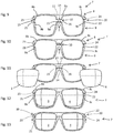
- the central portion 9a of the lower part 9 of contour 7 comprises two tabs 15, 16 which extend upwards and each have a claw 17, 18. These claws 17, 18 are arranged facing each other, at the respective upper ends of said These tabs 15, 16 have, in combination, a shape complementary to that of the tooth 14. The insertion of the tabs 15, 16 inside the holes 12, 13 makes it possible to engage the claws 17, 18 on tooth 14, as illustrated by Figures 9 to 11 .
- Interlocking systems 19, 20 are implemented on the lateral ends of the contour 7, between the upper part 8 and the lower part 9.
- the lateral ends 9b, 9c of the lower part 9 each comprise a pad 21, 22 which extends upwards, as illustrated in particular by the figures 2 and 9 to 12 .
- the lateral ends 8b, 8c of the upper part 8 each comprise an orifice 23, 24 configured to receive the pad 21, 22 respectively, as illustrated in particular by the figures 2 and 9 to 13 .
- the lateral ends 8b, 8c of the upper part 8 remain clear vis-à-vis the lateral ends 9b, 9c of the lower part 9, which facilitates the introduction of the glasses 3, 4 inside the contour 7 as illustrated by Figures 11 and 12 .
- the interlocking systems 19, 20 are placed between the lateral ends 8b, 8c of the upper part 8 and the lateral ends 9b, 9c of the lower part 9.
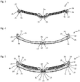
- the Figures 3 to 5 illustrate a first embodiment of the contour 7 of the frame 2.
- the lower part 9 of the contour 7 comprises at each of its lateral ends 9b, 9c, a first longitudinal semi-cylindrical portion 25, 26 which has a first recess 27, 28.
- the upper part 8 of the contour 7 comprises at each of its lateral ends 8b, 8c, a second semi-cylindrical longitudinal portion 29, 30 which has a second recess 31, 32 of complementary shape to the first recess 27, 28.
- the longitudinal direction is defined by the axes of pivoting of the branches 5, 6 vis-à-vis the contour 7.
- the combination of the first semi-cylindrical longitudinal portion 25, 26 of the lower part 9 with the second semi-cylindrical longitudinal portion 29, 30 of the upper part 8, at each of the lateral ends 7b, 7c of the contour 7, makes it possible to constitute two hollow cylinders 33, 34 which each have a slot 35, 36, as shown in FIG. figure 5 .
- the shape of the cut in the longitudinal direction may be variable, for example a straight cut in a plane parallel to the pivot axis, or a serpentine or zigzag cut which promotes the reduction of mobility between said first and second portions. once joined, both in the direction of the pivot axis and perpendicular to said axis.
- the branches 5, 6 each comprise at their proximal end 5a, 6a, an upper flat 37, 38 and a lower flat 39, 40 which are separated from each other by a distance corresponding to the length of the hollow cylinders 33, 34.
- An axis 41, 42 extends vertically between the upper flat 37, 38 and the lower flat 39, 40, for each of the branches 5, 6.
- the slots 35, 36 on the hollow cylinders 33, 34 at the ends lateral 7b, 7c of the contour 7, are proportional to the diameter of the shafts 41, 42 on the branches 5, 6, so as to allow the latching of said shafts 41, 42 inside said respective hollow cylinders 33, 34, by inserting them through said slots 35, 36.
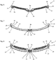
- FIG. 6 to 8 illustrate an alternative embodiment of the first semi-cylindrical longitudinal portions 25, 26 on the lower part 9 and second longitudinal semi-cylindrical portions 29, 30 on the upper part 8, for the implementation of the cylinders recesses 33, 34 provided with a slot 35, 36.
- Their characteristics are similar to those of the variant described above and illustrated in FIG. Figures 3 to 5 only they change their semi-cylindrical forms.
- the recesses 27, 28 on the first semi-cylindrical longitudinal portions 25, 26 extend more or less over a quarter circle and are oriented towards the outer sides, the lateral ends 9b, 9c of the lower part 9.
- the recesses 27, 28 on the first semi-cylindrical longitudinal portions 25, 26 have more or less the shape of a semicircle and are oriented towards the rear side of the contour 7, at the lateral ends 9b, 9c of the lower part 9.
- the recesses 31, 32 on the second semi-cylindrical longitudinal portions 29, 30 extend over a little more than one semicircle and are oriented towards the inner sides, at the lateral ends 8b, 8c of the upper part 8.
- the recesses 31, 32 on the second semi-cylindrical longitudinal portions 29, 30 extend over a little more than a quarter of a circle and are bent towards the inner face 43 of the upper part 8, which makes it possible to form extensions 44, 45 on these second semi-cylindrical longitudinal portions 29, 30, at the lateral ends 7b, 7c of the contour 7, as illustrated in FIG. Figures 7 and 8 , these extensions 44, 45 being of smaller thickness than the extensions 44, 45 similar implemented for the first variant, as illustrated in FIG. Figures 4 and 5 .
- bearing faces 46, 47 on the upper flats 37 and lower 39 of the first branch 5 abut against contact faces 48, 49 arranged on the lateral ends 8b, 9b of the upper 8 and lower 9 parts.
- bearing faces 50, 51 on the upper and lower flats 40 of the second leg 6 abut against contact faces 52, 53 arranged on the lateral ends 8c, 9c of the upper and lower portions 8 and 9.
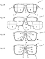
- FIGS 14 to 17 illustrate the disassembly of the contour 7 to allow the removal of the glasses 3, 4.
- this disassembly is possible only once the branches 5, 6 clear of the lateral ends 7b, 7c of the contour 7, since the upper flats 37, 38 and lower 39, 40 prevent the disengagement of the disengagement systems 19, 20.
- the interlocking systems 19, 20 between the lateral ends 8b, 8c, 9b, 9c of the upper 8 and lower 9 parts can be disengaged, which allows to move slightly apart the circular elements 54, 55 of the lower part 9 thanks to its flexibility, then to clear the glasses 3, 4.
- the latching system 10 on the central portion 7a of the contour remains in operation while the interlocking systems 19, 20 are disengaged.
- the circular elements 54, 55 are interconnected by a nasal support element 56.
- the flexibility of the lower part 9 makes it possible to exert pressure in the direction of the arrows 57, 58 illustrated in FIG. figure 16 on the lateral sides 56a, 56b of this nasal support element 56, which allows the claws 17, 18 to be slightly spread apart at the ends of the lugs 15, 16, so as to disengage these claws 17, 18 from the tooth 14, and then extracting the tabs 15, 16 from the housing zone 11 in the direction of the arrow 59 illustrated in FIG.
- FIG 17 for unclipping the central portion 8a of the upper portion 8 vis-à-vis the central portion 9a of the lower portion 9.
- the clearance in the direction of the arrow 59 is effected while maintaining the lateral sides 56a, 56b of the nasal support member 56.
- first semi-cylindrical longitudinal portions 25, 26 on the lower part 9 of the contour 7 each constitute a first longitudinal element of semi-connection.
- second semi-cylindrical longitudinal portions 29, 30 on the upper part 8 of the contour 7 each constitute a second longitudinal element of semi-connection.
- first and second longitudinal elements of semi-connection are complementary and together form a first female connecting element during assembly of the lower part 9 and the upper part 8, forming said contour 7.
- the axes 41, 42 on the branches 5, 6 form second male connecting elements which each engage in a first connecting element.
- first connecting elements would be of the male type and the second connecting elements would be of the female type.
- first 25, 26 and 29 seconds, 30 longitudinal semi-cylindrical portions each forming a recess 27, 28, 31, 32 could be replaced by first and second full semi-cylindrical longitudinal portions each forming a semi-axis, 1 assembly of the upper part 8 with the lower part 9 making it possible to associate, at each of the lateral ends 7b, 7c of the contour 7, said first and second full semi-cylindrical longitudinal portions so as to constitute a complete connecting axis (not illustrated).
- the axes 41, 42 on the branches 5, 6 would be removed and replaced by cylindrical notches provided with a slot (not shown), arranged coaxially on the inner faces 37a, 38a, 39a, 40a. upper flats 37, 38 and lower 39, 40 illustrated in figures 2 and 18 , so as to constitute female pivot connecting elements for snap reception, said complete axes.
- the Figures 22 and 23 show a variant of the latching system 10 previously described on the embodiment of the Figures 1 to 21 , which is implemented in the central portion 7a of the contour 7, between the upper part 8 and the lower part 9.
- the central portion 8a of the upper part 8 of the contour 7 comprises a housing zone 11 which has at its lower edge It has a single hole 12.
- An insert 60 is configured to be fitted into the housing zone 11 by the upper side of the central portion 8a, as shown in FIGS. Figures 22 and 23 .
- This insert comprises an inverted T-shaped tooth 14 which extends downwardly inside the housing 11, as it appears on the Figures 22 and 23 .
- the central portion 9a of the lower portion 9 of the contour 7 comprises two tabs 15, 16 which extend upwards and each have a claw 17, 18.
- These claws 17, 18 are arranged opposite one another at the respective upper ends of said tabs 15, 16.
- These tabs 15, 16 have in combination a shape complementary to that of the tooth 14.
- the insertion of the tabs 15, 16 and the insert 60 into the housing zone 11 in the direction of the arrows 61, 62, allows to engage the claws 17, 18 on the tooth 14, as illustrated by the Figures 22 and 23 .
- the circular elements 54, 55 are interconnected by a nasal support element 56.
- the flexibility of the lower part 9 makes it possible to exert pressure in the direction of the arrows 57, 58 illustrated in FIG.
- the figure 24 shows another variant of this declutching system 10 implemented in the central portion 7a of the contour 7, between the upper portion 8 and the lower portion 9.
- the central portion 8a of the upper portion 8 of the contour 7 comprises a housing zone 11 which has at its lower edge a single hole 12.
- the housing zone 11 comprises on its inner lateral sides two teeth 14a, 14b arranged vis-à-vis, as it appears on the figure 24 .
- the central portion 9a of the lower portion 9 of the contour 7 comprises two tabs 15, 16 which extend upwards and each have a claw 17, 18. These claws 17, 18 are arranged in opposition to one another relative to the other. at the respective upper ends of said tabs 15, 16.
- the insertion of the tabs 15, 16 into the housing zone 11 allows the claws 17, 18 to be engaged on the respective teeth 14a, 14b, as illustrated by FIG. figure 24 .
- the flexibility of the lower part 9 makes it possible to exert pressure in the direction of the arrows 57, 58 illustrated in FIG. figure 24 on the lateral sides 56a, 56b of this nasal support element 56, which makes it possible to bring the claws 17, 18 slightly closer to the ends of the lugs 15, 16, so as to disengage these claws 17, 18 from the teeth 14a, 14b, then extracting the lugs 15, 16 from the housing zone 11, for unclipping the central portion 8a of the upper portion 8 vis-à-vis the central portion 9a of the lower portion 9.
- the material used for the design of the upper part 8 and the lower part 9 will be chosen so as to offer sufficient flexibility at the slots 35, 36, circular elements 54, 55, lateral sides 56a, 56a of the nasal support member 56 and tabs 15, 16.
- the material used will for example be nylon, polycarbonate or acetate, or any other suitable material.
- the invention also provides a kit for the implementation of a pair of glasses 1 can be customized according to the desires of the user or his dress.
- the kit comprises several pairs of branches 5, 6 with colors and / or varied patterns.
- the kit comprises several upper parts 8 and several lower parts 9 with different colors and / or patterns.
- the kit further comprises several pairs of glasses 3, 4, for example pairs of corrective lenses with different glass shades, and pairs of sunglasses.
- the invention also relates to a kit comprising a pair of spectacles 1 having the aforementioned characteristics according to one or other of the variants described, or even any other variant, and a tool 63 which makes it possible to easily dismount the branches 5, 6 7, to customize said pair of glasses 1.
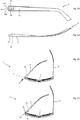
- This tool 63 has the shape of a stick as illustrated in FIG. Figures 25 and 26 , with a body 64 configured to be manipulated and a head 65 configured to engage an opening 69 on the branch 5, at its connection with the contour 7, as illustrated in particular by the figure 27 , the branch 5 being in the folded position against the contour 7.
- the branch 5 comprises a housing zone 66 whose shape corresponds to that of the tool 63 illustrated in FIG. figure 25 and 26 , with slightly larger dimensions, so as to allow the recessing of the tool 63 in this housing zone 66.
- the housing zone 66 comprises a magnet 67, illustrated in FIG. Figures 27 to 29 .
- the tool 63 comprises a magnet 68 illustrated in Figures 25 and 26 .
- This tool 63 can remain permanently present on the pair of glasses 1.
- This tool 63 can be integrated into the aforementioned kit which includes several upper parts 8 and several lower parts 9, and several pairs of glasses 3, 4, to allow the customization of the pair of glasses 1.
Landscapes
- Physics & Mathematics (AREA)
- Health & Medical Sciences (AREA)
- Ophthalmology & Optometry (AREA)
- General Physics & Mathematics (AREA)
- Optics & Photonics (AREA)
- General Health & Medical Sciences (AREA)
- Eyeglasses (AREA)
Claims (13)
- Brille (1), umfassend eine Fassung, die einen Rahmen (7) und zwei Bügel (5, 6) umfasst, welche in Gelenkverbindung mit den seitlichen Enden (7b, 7c) des Rahmens montiert sind, der mit einem oberen Teil (8), mit einem unteren Teil (9) und mit Fügemitteln (10, 19, 20) zwischen den Teilen ausgestattet ist, wobei die Schwenkachse eine Längsrichtung definiert, wobei die Brille dadurch gekennzeichnet ist, dass der obere Teil an jedem seiner seitlichen Enden (8b, 8c) einen ersten Halbverbindungs-Längsabschnitt (29, 30) umfasst, und der untere Teil an jedem seiner seitlichen Enden (9b, 9c) einen zweiten Halbverbindungs-Längsabschnitt (25, 26) umfasst, wobei der erste und zweite Halbverbindungs-Längsabschnitt durch Ausführen eines Schnitts in der Längsrichtung eines ersten, weiblichen oder männlichen, Verbindungselements (33, 34) erhalten werden, wobei der erste und zweite Halbverbindungs-Längsabschnitt komplementär und dafür ausgebildet sind, beim Zusammenfügen des oberen Teils und des unteren Teils das erste Verbindungselement zu bilden, wobei das erste Verbindungselement dafür ausgebildet ist, ein zweites, männliches oder weibliches, Verbindungselement (41, 42) aufzunehmen, welches am Ende (5a, 6a) jedes jeweiligen Bügels angeordnet ist.
- Brille (1) nach Anspruch 1, wobei der obere Teil (8) an jedem seiner seitlichen Enden (8b, 8c) einen ersten halbzylindrischen Hohlabschnitt (29, 30) umfasst, und der untere Teil (9) an jedem seiner seitlichen Enden (9b, 9c) einen zweiten halbzylindrischen Hohlabschnitt (25, 26) umfasst, wobei der erste und zweite halbzylindrische Abschnitt komplementär und derart ausgebildet sind, dass beim Zusammenfügen des oberen Teils und des unteren Teils der erste und zweite Abschnitt einen Hohlzylinder (33, 34) bilden, welcher mit einem Längsschlitz (35, 36) ausgestattet ist, der dafür bemessen ist, das Einklicken einer Achse (41, 42), welche am Ende (5a, 6a) jedes jeweiligen Bügels (5, 6) angeordnet ist, zu ermöglichen.
- Brille (1) nach einem der Ansprüche 1 oder 2, wobei an den Enden (5a, 6a) der Bügel (5, 6) Anschlagmittel (37, 38, 39, 40) angeordnet sind, wobei die Anschlagmittel dafür ausgebildet sind, beim Montieren jedes Bügels am Rahmen (7) die Längstranslation des ersten Halbverbindungs-Längsabschnitts (25, 26) gegenüber dem zweiten Halbverbindungs-Längsabschnitt (29, 30) zu blockieren.
- Brille (1) nach Anspruch 3 in Verbindung mit Anspruch 2, wobei jeder Bügel (5, 6) an seinem Ende (5a, 6a) eine obere Abflachung (37, 38) und eine untere Abflachung (39, 40) umfasst, zwischen denen sich die Achse (41, 42) erstreckt, wobei die obere und untere Abflachung Anschläge bilden, die dafür ausgebildet sind, die Translation des ersten halbzylindrischen Abschnitts (25, 26) gegenüber dem zweiten halbzylindrischen Abschnitt (29, 30) entlang der Achse zu blockieren.
- Brille (1) nach einem der Ansprüche 1 bis 4, wobei die Fügemittel ein Klicksystem (1) umfassen, welches in einem mittleren Abschnitt (7a) des Rahmens zwischen dem oberen Teil (8) und dem unteren Teil (9) des Rahmens (7) angeordnet ist.
- Brille (1) nach Anspruch 5, wobei der untere Teil (9) des Rahmens (7) in seinem mittleren Abschnitt (9a) ein Nasenauflageelement (56) umfasst, wobei das Klicksystem (10) dafür ausgebildet ist, das Ausklicken des unteren Teils gegenüber dem oberen Teil (8) durch Drücken auf das Nasenauflageelement zu unterstützen.
- Brille (1) nach einem der Ansprüche 1 bis 6, wobei die Fügemittel zwei Stecksysteme (19, 20) umfassen, welche jeweils auf Ebene der zwei seitlichen Enden (7b, 7c) des Rahmens zwischen dem oberen Teil (8) und dem unteren Teil (9) des Rahmens (7) angeordnet sind.
- Brille (1) nach Anspruch 2, wobei der erste halbzylindrische Abschnitt (25, 26) und der zweite halbzylindrische Abschnitt (29, 30) dafür ausgebildet sind, die Flexibilität von mindestens einem der zylindrischen Abschnitte derart zu erhöhen, dass das Spreizen des Schlitzes (35, 36) beim Einklicken oder Ausklicken der Achse (41, 42) des Bügels (5, 6) erleichtert wird.
- Set zum Zusammenbauen einer Brille (1) nach einem der Ansprüche 1 bis 8, das mindestens einen oberen Teil (8), mindestens einen unteren Teil (9), mindestens ein Paar Gläser (3, 4) und mindestens ein Paar Bügel (5, 6) umfasst.
- Set nach Anspruch 9, das mindestens ein Paar Korrekturgläser (5, 6) und ein Paar Sonnengläser umfasst.
- Set nach einem der Ansprüche 9 oder 10, das mindestens zwei Paar Bügel (5, 6) unterschiedlicher Farben oder Muster umfasst.
- Set, umfassend eine Brille (1) nach einem der Ansprüche 1 bis 8 und ein Werkzeug (63), das dafür ausgebildet ist, das Abmontieren der Bügel (5, 6) durch Einführen des Werkzeugs in jeden Bügel und durch Öffnen des Bügels in Bezug auf den Rahmen (7) nach außen hin zu ermöglichen.
- Set nach Anspruch 12, wobei einer der Bügel (5) eine Unterbringungszone (66) umfasst, die dafür ausgebildet ist, das Werkzeug (63) aufzunehmen und in Verstauposition zu halten.
Applications Claiming Priority (2)
| Application Number | Priority Date | Filing Date | Title |
|---|---|---|---|
| FR1457529A FR3024556B1 (fr) | 2014-08-01 | 2014-08-01 | Paire de lunettes modulable |
| PCT/FR2015/052048 WO2016016555A1 (fr) | 2014-08-01 | 2015-07-23 | Paire de lunettes modulable |
Publications (2)
| Publication Number | Publication Date |
|---|---|
| EP3175283A1 EP3175283A1 (de) | 2017-06-07 |
| EP3175283B1 true EP3175283B1 (de) | 2018-06-06 |
Family
ID=51519146
Family Applications (1)
| Application Number | Title | Priority Date | Filing Date |
|---|---|---|---|
| EP15754271.3A Not-in-force EP3175283B1 (de) | 2014-08-01 | 2015-07-23 | Modulare brille |
Country Status (5)
| Country | Link |
|---|---|
| US (1) | US20170219843A1 (de) |
| EP (1) | EP3175283B1 (de) |
| CN (1) | CN106796357A (de) |
| FR (1) | FR3024556B1 (de) |
| WO (1) | WO2016016555A1 (de) |
Families Citing this family (13)
| Publication number | Priority date | Publication date | Assignee | Title |
|---|---|---|---|---|
| IT201600082287A1 (it) * | 2016-08-04 | 2018-02-04 | Salvatore Reina | Struttura di occhiali |
| IT201700053578A1 (it) * | 2017-05-17 | 2018-11-17 | Camilla Pataro | Montatura per occhiali |
| US10345616B2 (en) * | 2017-09-08 | 2019-07-09 | Hsien Chang Optical Industrial Co., Ltd. | Eyeglasses assembly structure |
| FR3077890B1 (fr) * | 2018-02-12 | 2023-03-31 | Laurent Albouy | Paire de lunettes comprenant un systeme de charniere flexible et une paire de branches interchangeable et kit associe |
| US10459244B1 (en) * | 2018-04-16 | 2019-10-29 | Min-Ching Tsai | Assembling structure for eyeglasses |
| CA3092773C (en) | 2018-10-23 | 2024-06-11 | Tecmen Electronics Co., Ltd. | Combination of a goggle and a face mask |
| CA3072496A1 (en) | 2019-02-28 | 2020-08-28 | Smith Sport Optics, Inc. | Eyewear lens interchange with magnetic latch |
| CN110262060B (zh) * | 2019-04-08 | 2020-12-01 | 永康奈叶科技有限公司 | 一种便于更换的眼镜 |
| CN115053169B (zh) * | 2020-02-05 | 2024-10-29 | 稻见昌之 | 镜框与镜片结构 |
| TWI714468B (zh) * | 2020-03-04 | 2020-12-21 | 雅德視國際股份有限公司 | 具透氣結構之眼鏡 |
| TWM621720U (zh) * | 2021-06-30 | 2022-01-01 | 董宜秉 | 全框軍用眼鏡結構 |
| CN115167007B (zh) * | 2022-08-02 | 2025-03-11 | 上海婷伊美科技有限公司 | 一种智能调节的离焦眼镜 |
| US20240231122A9 (en) * | 2022-10-19 | 2024-07-11 | AJsens Inc. | Detachable Three-Piece Eyeglasses Suitable for Single Eyewear |
Family Cites Families (12)
| Publication number | Priority date | Publication date | Assignee | Title |
|---|---|---|---|---|
| GB734208A (en) * | 1952-11-25 | 1955-07-27 | Albert Alexander Irons | Improvements in or relating to spectacle frames |
| US4153347A (en) * | 1977-06-08 | 1979-05-08 | Myer C Randolph | Eyeglass frames with removable, interchangeable lenses, rims and temple pieces |
| DE20101580U1 (de) * | 2000-07-13 | 2001-09-06 | Nazerzadeh, Babak, 22159 Hamburg | Multifunktionsbrille |
| TW200947015A (en) | 2008-05-09 | 2009-11-16 | Qef Design Corp | Fast detachable eyeglasses |
| US7931365B2 (en) * | 2009-08-04 | 2011-04-26 | Jay-Y Enterprise Co., Inc. | Replaceable-lens eyewear and kit |
| US9351881B2 (en) * | 2009-10-22 | 2016-05-31 | Readymax, Inc. | Retractable earplug apparatus for an eyewear assembly |
| NZ585644A (en) | 2010-05-26 | 2012-12-21 | Francis William Austin | Modular Eye Glasses with the frame part forming a pivot shaft and the temple arms adapted to attach to the pivot shaft |
| NZ589698A (en) * | 2010-12-03 | 2013-07-26 | Francis William Austin | Eyeglass Hinge Assembly which allows removal of the arms |
| GB2491210B (en) * | 2011-07-04 | 2013-05-15 | Kenneth Michael Smith | Improved spectacle frame |
| US8608309B2 (en) * | 2011-12-30 | 2013-12-17 | A New Vision Llc | Eyeglass system |
| US8757798B2 (en) * | 2012-08-31 | 2014-06-24 | Cody Air LLC | Eyewear frame |
| CN203414687U (zh) * | 2013-08-07 | 2014-01-29 | 钟志安 | 可拆换组合眼镜 |
-
2014
- 2014-08-01 FR FR1457529A patent/FR3024556B1/fr not_active Expired - Fee Related
-
2015
- 2015-07-23 US US15/500,681 patent/US20170219843A1/en not_active Abandoned
- 2015-07-23 WO PCT/FR2015/052048 patent/WO2016016555A1/fr not_active Ceased
- 2015-07-23 EP EP15754271.3A patent/EP3175283B1/de not_active Not-in-force
- 2015-07-23 CN CN201580041748.9A patent/CN106796357A/zh active Pending
Non-Patent Citations (1)
| Title |
|---|
| None * |
Also Published As
| Publication number | Publication date |
|---|---|
| EP3175283A1 (de) | 2017-06-07 |
| US20170219843A1 (en) | 2017-08-03 |
| CN106796357A (zh) | 2017-05-31 |
| FR3024556B1 (fr) | 2016-09-02 |
| FR3024556A1 (fr) | 2016-02-05 |
| WO2016016555A1 (fr) | 2016-02-04 |
Similar Documents
| Publication | Publication Date | Title |
|---|---|---|
| EP3175283B1 (de) | Modulare brille | |
| EP1428451B1 (de) | Gliederarmband mit Gelenkverbindung | |
| EP0549979B1 (de) | Gliederarmband, insbesondere für Uhren | |
| EP2783255B1 (de) | Vorrichtung angegliedert mit schraubenloser gelenk | |
| WO2015185831A1 (fr) | Monture de lunettes a branches en lames de métal amovibles clipsees | |
| EP2895902B1 (de) | Einteiliger ausrichtungsfassungshalter mit verriegelungsvorrichtung | |
| EP3228202B1 (de) | Skischuh | |
| EP2856245B1 (de) | Brillenrahmen | |
| FR2846642A1 (fr) | Maillon pour le tapis de convoyage d'objets quelconques | |
| EP2495606B1 (de) | Brillengestell mit clip-befestigtem Bügel | |
| FR3002726A1 (fr) | Moyen de liaison amovible entre deux elements d'un article de bijouterie ou d'un accessoire de mode | |
| CH689245A5 (fr) | Ensemble de maillons, notamment pour la réalisation de bracelets. | |
| EP3598205A1 (de) | Brillengestell mit seitlich eingesetztem element | |
| WO1994016654A1 (fr) | Paire de lunettes modulable | |
| FR2870012A1 (fr) | Monture de lunettes associee par pression a un element de transformation | |
| EP1554625A1 (de) | Abschirmung für brillen und komponenten zur herstellung einer solchen abschirmung | |
| WO2018087457A1 (fr) | Charnière pour monture de lunettes | |
| EP4296760B1 (de) | Brille mit verriegelungsstift und montageverfahren dafür | |
| FR2732083A1 (fr) | Dispositif de connexion a montage simplifie pour assembler deux profiles | |
| FR3011344A1 (fr) | Monture de lunettes dont les branches sont reliees au tenon par un axe d'articulation forme par une douille a vis | |
| WO2024132699A1 (fr) | Mécanisme d'interchangeabilité de bracelet de montre | |
| CH720341A2 (fr) | Mécanisme de fixation pour bracelet interchangeable à un boîtier et boîtier de montre | |
| FR3133454A1 (fr) | Système de charnière pour monture de lunettes et lunettes comportant un tel système de charnière | |
| WO2015044610A2 (fr) | Monture de lunettes modulaire avec un systeme de fixation amovible des branches a la face | |
| FR2868914A1 (fr) | Outil a scarifier des patons et porte-outils equipes d'un tel outil |
Legal Events
| Date | Code | Title | Description |
|---|---|---|---|
| STAA | Information on the status of an ep patent application or granted ep patent |
Free format text: STATUS: THE INTERNATIONAL PUBLICATION HAS BEEN MADE |
|
| 17P | Request for examination filed |
Effective date: 20170206 |
|
| AK | Designated contracting states |
Kind code of ref document: A1 Designated state(s): AL AT BE BG CH CY CZ DE DK EE ES FI FR GB GR HR HU IE IS IT LI LT LU LV MC MK MT NL NO PL PT RO RS SE SI SK SM TR |
|
| AX | Request for extension of the european patent |
Extension state: BA ME |
|
| PUAI | Public reference made under article 153(3) epc to a published international application that has entered the european phase |
Free format text: ORIGINAL CODE: 0009012 |
|
| STAA | Information on the status of an ep patent application or granted ep patent |
Free format text: STATUS: REQUEST FOR EXAMINATION WAS MADE |
|
| REG | Reference to a national code |
Ref country code: DE Ref legal event code: R079 Ref document number: 602015012036 Country of ref document: DE Free format text: PREVIOUS MAIN CLASS: G02C0005220000 Ipc: G02C0001080000 |
|
| DAV | Request for validation of the european patent (deleted) | ||
| DAX | Request for extension of the european patent (deleted) | ||
| RIC1 | Information provided on ipc code assigned before grant |
Ipc: G02C 7/10 20060101ALI20171107BHEP Ipc: G02C 5/14 20060101ALI20171107BHEP Ipc: G02C 5/22 20060101ALI20171107BHEP Ipc: G02C 7/02 20060101ALI20171107BHEP Ipc: G02C 1/08 20060101AFI20171107BHEP |
|
| GRAP | Despatch of communication of intention to grant a patent |
Free format text: ORIGINAL CODE: EPIDOSNIGR1 |
|
| STAA | Information on the status of an ep patent application or granted ep patent |
Free format text: STATUS: GRANT OF PATENT IS INTENDED |
|
| INTG | Intention to grant announced |
Effective date: 20180117 |
|
| GRAS | Grant fee paid |
Free format text: ORIGINAL CODE: EPIDOSNIGR3 |
|
| GRAA | (expected) grant |
Free format text: ORIGINAL CODE: 0009210 |
|
| STAA | Information on the status of an ep patent application or granted ep patent |
Free format text: STATUS: THE PATENT HAS BEEN GRANTED |
|
| AK | Designated contracting states |
Kind code of ref document: B1 Designated state(s): AL AT BE BG CH CY CZ DE DK EE ES FI FR GB GR HR HU IE IS IT LI LT LU LV MC MK MT NL NO PL PT RO RS SE SI SK SM TR |
|
| REG | Reference to a national code |
Ref country code: GB Ref legal event code: FG4D Free format text: NOT ENGLISH |
|
| REG | Reference to a national code |
Ref country code: CH Ref legal event code: EP Ref country code: AT Ref legal event code: REF Ref document number: 1006742 Country of ref document: AT Kind code of ref document: T Effective date: 20180615 |
|
| REG | Reference to a national code |
Ref country code: IE Ref legal event code: FG4D Free format text: LANGUAGE OF EP DOCUMENT: FRENCH |
|
| REG | Reference to a national code |
Ref country code: DE Ref legal event code: R096 Ref document number: 602015012036 Country of ref document: DE |
|
| REG | Reference to a national code |
Ref country code: FR Ref legal event code: PLFP Year of fee payment: 4 |
|
| REG | Reference to a national code |
Ref country code: NL Ref legal event code: MP Effective date: 20180606 |
|
| REG | Reference to a national code |
Ref country code: LT Ref legal event code: MG4D |
|
| PG25 | Lapsed in a contracting state [announced via postgrant information from national office to epo] |
Ref country code: NO Free format text: LAPSE BECAUSE OF FAILURE TO SUBMIT A TRANSLATION OF THE DESCRIPTION OR TO PAY THE FEE WITHIN THE PRESCRIBED TIME-LIMIT Effective date: 20180906 Ref country code: FI Free format text: LAPSE BECAUSE OF FAILURE TO SUBMIT A TRANSLATION OF THE DESCRIPTION OR TO PAY THE FEE WITHIN THE PRESCRIBED TIME-LIMIT Effective date: 20180606 Ref country code: BG Free format text: LAPSE BECAUSE OF FAILURE TO SUBMIT A TRANSLATION OF THE DESCRIPTION OR TO PAY THE FEE WITHIN THE PRESCRIBED TIME-LIMIT Effective date: 20180906 Ref country code: CY Free format text: LAPSE BECAUSE OF FAILURE TO SUBMIT A TRANSLATION OF THE DESCRIPTION OR TO PAY THE FEE WITHIN THE PRESCRIBED TIME-LIMIT Effective date: 20180606 Ref country code: LT Free format text: LAPSE BECAUSE OF FAILURE TO SUBMIT A TRANSLATION OF THE DESCRIPTION OR TO PAY THE FEE WITHIN THE PRESCRIBED TIME-LIMIT Effective date: 20180606 Ref country code: SE Free format text: LAPSE BECAUSE OF FAILURE TO SUBMIT A TRANSLATION OF THE DESCRIPTION OR TO PAY THE FEE WITHIN THE PRESCRIBED TIME-LIMIT Effective date: 20180606 |
|
| PG25 | Lapsed in a contracting state [announced via postgrant information from national office to epo] |
Ref country code: LV Free format text: LAPSE BECAUSE OF FAILURE TO SUBMIT A TRANSLATION OF THE DESCRIPTION OR TO PAY THE FEE WITHIN THE PRESCRIBED TIME-LIMIT Effective date: 20180606 Ref country code: HR Free format text: LAPSE BECAUSE OF FAILURE TO SUBMIT A TRANSLATION OF THE DESCRIPTION OR TO PAY THE FEE WITHIN THE PRESCRIBED TIME-LIMIT Effective date: 20180606 Ref country code: RS Free format text: LAPSE BECAUSE OF FAILURE TO SUBMIT A TRANSLATION OF THE DESCRIPTION OR TO PAY THE FEE WITHIN THE PRESCRIBED TIME-LIMIT Effective date: 20180606 Ref country code: GR Free format text: LAPSE BECAUSE OF FAILURE TO SUBMIT A TRANSLATION OF THE DESCRIPTION OR TO PAY THE FEE WITHIN THE PRESCRIBED TIME-LIMIT Effective date: 20180907 |
|
| REG | Reference to a national code |
Ref country code: AT Ref legal event code: MK05 Ref document number: 1006742 Country of ref document: AT Kind code of ref document: T Effective date: 20180606 |
|
| PG25 | Lapsed in a contracting state [announced via postgrant information from national office to epo] |
Ref country code: NL Free format text: LAPSE BECAUSE OF FAILURE TO SUBMIT A TRANSLATION OF THE DESCRIPTION OR TO PAY THE FEE WITHIN THE PRESCRIBED TIME-LIMIT Effective date: 20180606 |
|
| PG25 | Lapsed in a contracting state [announced via postgrant information from national office to epo] |
Ref country code: IS Free format text: LAPSE BECAUSE OF FAILURE TO SUBMIT A TRANSLATION OF THE DESCRIPTION OR TO PAY THE FEE WITHIN THE PRESCRIBED TIME-LIMIT Effective date: 20181006 Ref country code: PL Free format text: LAPSE BECAUSE OF FAILURE TO SUBMIT A TRANSLATION OF THE DESCRIPTION OR TO PAY THE FEE WITHIN THE PRESCRIBED TIME-LIMIT Effective date: 20180606 Ref country code: SK Free format text: LAPSE BECAUSE OF FAILURE TO SUBMIT A TRANSLATION OF THE DESCRIPTION OR TO PAY THE FEE WITHIN THE PRESCRIBED TIME-LIMIT Effective date: 20180606 Ref country code: CZ Free format text: LAPSE BECAUSE OF FAILURE TO SUBMIT A TRANSLATION OF THE DESCRIPTION OR TO PAY THE FEE WITHIN THE PRESCRIBED TIME-LIMIT Effective date: 20180606 Ref country code: RO Free format text: LAPSE BECAUSE OF FAILURE TO SUBMIT A TRANSLATION OF THE DESCRIPTION OR TO PAY THE FEE WITHIN THE PRESCRIBED TIME-LIMIT Effective date: 20180606 Ref country code: EE Free format text: LAPSE BECAUSE OF FAILURE TO SUBMIT A TRANSLATION OF THE DESCRIPTION OR TO PAY THE FEE WITHIN THE PRESCRIBED TIME-LIMIT Effective date: 20180606 Ref country code: AT Free format text: LAPSE BECAUSE OF FAILURE TO SUBMIT A TRANSLATION OF THE DESCRIPTION OR TO PAY THE FEE WITHIN THE PRESCRIBED TIME-LIMIT Effective date: 20180606 |
|
| PG25 | Lapsed in a contracting state [announced via postgrant information from national office to epo] |
Ref country code: IT Free format text: LAPSE BECAUSE OF FAILURE TO SUBMIT A TRANSLATION OF THE DESCRIPTION OR TO PAY THE FEE WITHIN THE PRESCRIBED TIME-LIMIT Effective date: 20180606 Ref country code: SM Free format text: LAPSE BECAUSE OF FAILURE TO SUBMIT A TRANSLATION OF THE DESCRIPTION OR TO PAY THE FEE WITHIN THE PRESCRIBED TIME-LIMIT Effective date: 20180606 |
|
| REG | Reference to a national code |
Ref country code: CH Ref legal event code: PL |
|
| REG | Reference to a national code |
Ref country code: DE Ref legal event code: R097 Ref document number: 602015012036 Country of ref document: DE |
|
| PG25 | Lapsed in a contracting state [announced via postgrant information from national office to epo] |
Ref country code: LU Free format text: LAPSE BECAUSE OF NON-PAYMENT OF DUE FEES Effective date: 20180723 Ref country code: MC Free format text: LAPSE BECAUSE OF FAILURE TO SUBMIT A TRANSLATION OF THE DESCRIPTION OR TO PAY THE FEE WITHIN THE PRESCRIBED TIME-LIMIT Effective date: 20180606 |
|
| REG | Reference to a national code |
Ref country code: BE Ref legal event code: MM Effective date: 20180731 |
|
| PLBE | No opposition filed within time limit |
Free format text: ORIGINAL CODE: 0009261 |
|
| STAA | Information on the status of an ep patent application or granted ep patent |
Free format text: STATUS: NO OPPOSITION FILED WITHIN TIME LIMIT |
|
| REG | Reference to a national code |
Ref country code: IE Ref legal event code: MM4A |
|
| PG25 | Lapsed in a contracting state [announced via postgrant information from national office to epo] |
Ref country code: IE Free format text: LAPSE BECAUSE OF NON-PAYMENT OF DUE FEES Effective date: 20180723 Ref country code: CH Free format text: LAPSE BECAUSE OF NON-PAYMENT OF DUE FEES Effective date: 20180731 Ref country code: LI Free format text: LAPSE BECAUSE OF NON-PAYMENT OF DUE FEES Effective date: 20180731 |
|
| 26N | No opposition filed |
Effective date: 20190307 |
|
| PG25 | Lapsed in a contracting state [announced via postgrant information from national office to epo] |
Ref country code: SI Free format text: LAPSE BECAUSE OF FAILURE TO SUBMIT A TRANSLATION OF THE DESCRIPTION OR TO PAY THE FEE WITHIN THE PRESCRIBED TIME-LIMIT Effective date: 20180606 Ref country code: BE Free format text: LAPSE BECAUSE OF NON-PAYMENT OF DUE FEES Effective date: 20180731 Ref country code: DK Free format text: LAPSE BECAUSE OF FAILURE TO SUBMIT A TRANSLATION OF THE DESCRIPTION OR TO PAY THE FEE WITHIN THE PRESCRIBED TIME-LIMIT Effective date: 20180606 |
|
| PG25 | Lapsed in a contracting state [announced via postgrant information from national office to epo] |
Ref country code: ES Free format text: LAPSE BECAUSE OF FAILURE TO SUBMIT A TRANSLATION OF THE DESCRIPTION OR TO PAY THE FEE WITHIN THE PRESCRIBED TIME-LIMIT Effective date: 20180606 |
|
| PGFP | Annual fee paid to national office [announced via postgrant information from national office to epo] |
Ref country code: DE Payment date: 20190731 Year of fee payment: 5 Ref country code: FR Payment date: 20190730 Year of fee payment: 5 |
|
| PG25 | Lapsed in a contracting state [announced via postgrant information from national office to epo] |
Ref country code: AL Free format text: LAPSE BECAUSE OF FAILURE TO SUBMIT A TRANSLATION OF THE DESCRIPTION OR TO PAY THE FEE WITHIN THE PRESCRIBED TIME-LIMIT Effective date: 20180606 |
|
| PG25 | Lapsed in a contracting state [announced via postgrant information from national office to epo] |
Ref country code: MT Free format text: LAPSE BECAUSE OF FAILURE TO SUBMIT A TRANSLATION OF THE DESCRIPTION OR TO PAY THE FEE WITHIN THE PRESCRIBED TIME-LIMIT Effective date: 20180606 |
|
| GBPC | Gb: european patent ceased through non-payment of renewal fee |
Effective date: 20190723 |
|
| PG25 | Lapsed in a contracting state [announced via postgrant information from national office to epo] |
Ref country code: TR Free format text: LAPSE BECAUSE OF FAILURE TO SUBMIT A TRANSLATION OF THE DESCRIPTION OR TO PAY THE FEE WITHIN THE PRESCRIBED TIME-LIMIT Effective date: 20180606 |
|
| PG25 | Lapsed in a contracting state [announced via postgrant information from national office to epo] |
Ref country code: GB Free format text: LAPSE BECAUSE OF NON-PAYMENT OF DUE FEES Effective date: 20190723 |
|
| PG25 | Lapsed in a contracting state [announced via postgrant information from national office to epo] |
Ref country code: PT Free format text: LAPSE BECAUSE OF FAILURE TO SUBMIT A TRANSLATION OF THE DESCRIPTION OR TO PAY THE FEE WITHIN THE PRESCRIBED TIME-LIMIT Effective date: 20180606 |
|
| PG25 | Lapsed in a contracting state [announced via postgrant information from national office to epo] |
Ref country code: HU Free format text: LAPSE BECAUSE OF FAILURE TO SUBMIT A TRANSLATION OF THE DESCRIPTION OR TO PAY THE FEE WITHIN THE PRESCRIBED TIME-LIMIT; INVALID AB INITIO Effective date: 20150723 Ref country code: MK Free format text: LAPSE BECAUSE OF NON-PAYMENT OF DUE FEES Effective date: 20180606 |
|
| REG | Reference to a national code |
Ref country code: DE Ref legal event code: R119 Ref document number: 602015012036 Country of ref document: DE |
|
| PG25 | Lapsed in a contracting state [announced via postgrant information from national office to epo] |
Ref country code: FR Free format text: LAPSE BECAUSE OF NON-PAYMENT OF DUE FEES Effective date: 20200731 |
|
| PG25 | Lapsed in a contracting state [announced via postgrant information from national office to epo] |
Ref country code: DE Free format text: LAPSE BECAUSE OF NON-PAYMENT OF DUE FEES Effective date: 20210202 |