EP3175437B1 - Instrument d'écriture tactile - Google Patents
Instrument d'écriture tactile Download PDFInfo
- Publication number
- EP3175437B1 EP3175437B1 EP15752939.7A EP15752939A EP3175437B1 EP 3175437 B1 EP3175437 B1 EP 3175437B1 EP 15752939 A EP15752939 A EP 15752939A EP 3175437 B1 EP3175437 B1 EP 3175437B1
- Authority
- EP
- European Patent Office
- Prior art keywords
- plate
- writing
- writing instrument
- opening
- partition plate
- Prior art date
- Legal status (The legal status is an assumption and is not a legal conclusion. Google has not performed a legal analysis and makes no representation as to the accuracy of the status listed.)
- Not-in-force
Links
Images


Classifications
-
- G—PHYSICS
- G09—EDUCATION; CRYPTOGRAPHY; DISPLAY; ADVERTISING; SEALS
- G09B—EDUCATIONAL OR DEMONSTRATION APPLIANCES; APPLIANCES FOR TEACHING, OR COMMUNICATING WITH, THE BLIND, DEAF OR MUTE; MODELS; PLANETARIA; GLOBES; MAPS; DIAGRAMS
- G09B21/00—Teaching, or communicating with, the blind, deaf or mute
- G09B21/02—Devices for Braille writing
-
- G—PHYSICS
- G09—EDUCATION; CRYPTOGRAPHY; DISPLAY; ADVERTISING; SEALS
- G09B—EDUCATIONAL OR DEMONSTRATION APPLIANCES; APPLIANCES FOR TEACHING, OR COMMUNICATING WITH, THE BLIND, DEAF OR MUTE; MODELS; PLANETARIA; GLOBES; MAPS; DIAGRAMS
- G09B21/00—Teaching, or communicating with, the blind, deaf or mute
- G09B21/001—Teaching or communicating with blind persons
- G09B21/003—Teaching or communicating with blind persons using tactile presentation of the information, e.g. Braille displays
-
- G—PHYSICS
- G09—EDUCATION; CRYPTOGRAPHY; DISPLAY; ADVERTISING; SEALS
- G09B—EDUCATIONAL OR DEMONSTRATION APPLIANCES; APPLIANCES FOR TEACHING, OR COMMUNICATING WITH, THE BLIND, DEAF OR MUTE; MODELS; PLANETARIA; GLOBES; MAPS; DIAGRAMS
- G09B21/00—Teaching, or communicating with, the blind, deaf or mute
- G09B21/001—Teaching or communicating with blind persons
- G09B21/003—Teaching or communicating with blind persons using tactile presentation of the information, e.g. Braille displays
- G09B21/004—Details of particular tactile cells, e.g. electro-mechanical or mechanical layout
Definitions
- the invention relates to a writing instrument for displaying a tactile perceptible dot pattern, in particular as Braille and / or as a graphic.
- Such a writing utensil which serves as an aid to visually impaired or blind persons, comprises a display panel having openings for receiving tactile perceptible elements or objects which can be moved into the corresponding apertures of the scoreboard according to the desired dot pattern to be displayed, usually Braille.
- a display device for the tactile detectable display of display elements (picture elements, graphics, drawing elements, characters, symbols) is known, which converts information output by a computer into Braille.
- individual indicator pins are actuated by actuators corresponding to the output of the computer on a touch surface.
- tactile detectable elements a metal ball, which can be moved by means of a controllable electromagnet from a position plane in a display plane and there in an opening. In order to hold the ball in the appropriate position, a metal plate is guided under the corresponding opening.
- a disadvantage of the known devices is in particular the high cost of the drive mechanisms for setting and holding the tactile pins or balls to or in the intended position in the display level (touch surface or display panel).
- the drive mechanisms for setting and holding the tactile pins or balls to or in the intended position in the display level touch surface or display panel.
- electromagnets especially when using electromagnets only relatively large display areas can be provided with only a relatively small number of scanning elements. These must also due to the limited minimal dimensions of the electromagnets as well as their magnetic interactions are positioned with relatively large magnetic active surfaces in correspondingly large distances from each other to avoid unwanted simultaneous lifting several balls.
- the invention has for its object to provide a particularly suitable writing instrument for displaying a tactile perceptible dot pattern, in particular as Braille and / or graphic.
- a tactile perceptible dot pattern with as large a number of touch points as possible should also be able to be generated on a relatively small display area.
- the writing instrument for indicating a tactile detectable dot pattern, a guide device with a lower plate in a lower layer plane and a top plate in a plane vertically spaced display plane and between these levels a partition plate and suitably above the top plate a write head assembly with a number of write heads, preferably in Form of controllable electromagnets on.
- This and the partition plate are relative to the guide device and thus relative to the top plate, which is a display surface, translationally movable.
- the top plate and the bottom plate have a number of matrix-like arranged in rows and columns openings in an opening grid. This is the same for both plates, so that the openings (Tastö réelleen) of the top plate with those (positional openings) of the lower plate are aligned, that are vertically arranged directly above one another. In the position openings of the lower plate are below also referred to as tactile tactile elements, preferably in the form of metallic balls. These are transported in the intended use of the writing instrument by means of the suitably designed as electromagnets write head assembly from the lower plate in the top sheet. The Probe elements then sit there in the selected Tastö réelleen and protrude at the top of the top plate from the Tastötechnischen at least slightly, so that they are perceptible by touching the fingers of an operator.
- the likewise translationally guided separating plate comprises a first plate area which is permeable to the tactile elements and a second plate area which adjoins the first plate area in the direction of movement or advancement and which is impervious to the feeler elements.
- the first plate region or section preferably has a number of recesses corresponding to the number of lines of the opening pattern of the tactile and / or positional openings. The number of recesses may also correspond to the number of write heads or the fraction thereof.
- the recesses of the partition plate come into coincidence with the openings of the lower and upper plate, so that a targeted transport channel of a corresponding opening of the lower plate via the corresponding recess of the partition plate is formed to the corresponding opening of the top plate.
- the adjoining in the direction of movement impermeable plate area of the partition plate then closes columns along the respective line loaded openings of the below also referred to as a display board top plate, so that there are remaining scanning elements remain in the display board even when the write head assembly.
- the number of write heads of the guided relative to the guide device in the direction of write head arrangement, which promotes according to the dot pattern to be displayed, the corresponding sensing elements from the lower plate in the top plate corresponds in a first variant, the number of lines of the opening pattern of the top plate (display panel).
- the number of write heads may be only a fraction of the number of lines. If, for example, the opening grid of the display panel comprises 384 touch points in 16 lines and 24 columns, four or eight write heads can be provided, for example, which pass over the corresponding four or two line groups of four or eight lines one after the other, around the corresponding openings of the top board tactile elements to equip.
- At least some of the write heads in the direction of movement are successively arranged one behind the other and row by row in the write head assembly.
- write heads and in particular electromagnets can be used whose dimensions or diameter is greater than the size of the openings of the upper and lower plate.
- Each write head is in this case suitably associated with one of the lines and thus with the openings of the top plate arranged one behind the other in the direction of movement.
- Each row of the opening pattern of the top and bottom plate is associated with a recess in the partition plate.
- Each of the write heads is assigned a respective recess in the permeable plate area of the partition plate.
- the recesses of the partition plate thus practically shield the transport channel between the corresponding, mutually aligned openings of the lower and upper plate laterally, ie in the horizontal partition plate level.
- a mutual disturbance of the write heads is particularly reliable prevented, especially if they are designed as preferably offset electromagnets.
- the write heads are always above this each associated recess in the partition plate during a caused by the controlled transport of the sensing elements writing process.
- the write head arrangement is also movable in the opposite direction to the translational movement direction and thus bidirectionally.
- the partition plate on both sides of the permeable for the sensing elements first plate area has a non-impermeable to the sensing elements second plate area.
- the display area or panel can thus be described and / or overwritten in both translational directions of movement.
- a further embodiment of the separating plate provides an opening window in the first plate region, which is permeable to the feeler elements.
- the opening window extends - viewed in the transverse direction to the direction of movement - over at least one line, but suitably over several or even all lines of the opening pattern or the fraction thereof.
- the recesses are then provided in the direction of movement both before and after the opening window.
- the opening window allows a targeted and time-saving deletion of the display panel by at the same time fall back those tactile elements (tactile elements) from the top plate in the lower plate whose openings are swept in the course of movement of the partition plate from the opening window.
- the subsequent recesses of the partition plate during the movement make it possible to reload the top plate - and thus to rewrite the display panel or surface - with feeler elements from the bottom plate.
- one of the two adjacent recess areas serves to transfer the feeler elements from the lower plate into the upper plate in a direction of movement, while the other of these two recessed areas serves to transfer the sensing elements from the lower plate into the upper plate in the other direction of movement.
- the second plate region of the separating plate which is impermeable to the feeler elements, can be detached from the first plate region, which is permeable to the feeler elements.
- a plate region that is impermeable to the feeler elements adjoins both sides of the first plate region which is permeable to the feeler elements.
- These panel-impermeable panel areas suitably have the same dimensions as the top panel (top panel).
- This embodiment of the separable partition plate allows separation of the equipped with the sensing elements according to the desired Tastpostenern top plate together with the impermeable to the sensing elements plate area (plate portion) of the guide device of the writing instrument, thus a correspondingly described display panel with tactile detectable, that is perceptible by touch Store Tast Vietnamesemuster separately or carried separately from the writing instrument.
- the separating plate is designed as a flexurally elastic separating strip.
- this separating tape is expediently taken together with the top plate and the lower plate from the writing instrument to store the appropriately equipped display panel separately.
- the tactile elements are preferably spherical, in particular with a ball diameter of (1.5 ⁇ 0.5) mm.
- the write heads are suitably controllable electromagnets.
- the inside diameter of the openings of the top plate is smaller than the ball diameter. This particular can be 1.0mm up 2,0mm and preferably 1,6mm.
- a foil or similar cover may be provided on the top plate.
- a display area of the display panel formed by the top plate in size DIN A4 9996 balls are provided with a ball diameter of 1.6 mm in a corresponding number of position openings of the lower plate at a pitch of 2.5 mm.
- the thickness of the display panel is then about 5mm, so that the display panel can not only be used stationary, but also several display panels, for example, in a bag, can be carried.
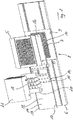
- the Fig. 1 and 2 show a writing instrument 1 for displaying a tactile detectable dot pattern on a display surface 2, on which sensing elements 3, preferably balls, as tactile elements (tactile majesty) are arranged.
- the display surface 2 is formed by matrix-like arranged in an opening grid in rows and columns Tastö réelleen 4, here in the form of circular holes in a top plate 5.
- the top plate 5 is based on a guide device 6 of the writing instrument 1 in a display level 7, in which the display surface 2 lies.
- Each tactile opening 4 of the top plate 5 corresponds to a touch point, which can take one of two possible states by either a probe element 3 protrudes through the opening 4, which can be felt, or the opening 4 is empty and the associated object 3 is located in one Vertically below the display level 7 arranged position level 8.
- a positional plane 8 is a lower plate 9 with arranged in the same opening grid position openings 10, in particular in the form of holes or blind holes, in which in turn feeler elements 3 removably eino.
- a partition plate 11 is disposed between the lower plate 9 and the upper plate 5. This is relative to the stationary in the guide device 6 arranged upper plate 5 and also stationary lower plate 9 in the direction of movement 12 translationally movable and this guided in the guide device 6 corresponding longitudinally displaceable.
- a manual or an electric motor drive which cooperates in a manner not shown with a perforation 13 on the longitudinal sides of the partition plate 11.
- the partition plate 11 has a recess area formed by a first plate area or section 14 and permeable to the feeler elements 3, with a number of recesses 15. Connected to these in the direction of movement 12 is a second plate area or section 16, which is impermeable to the feeler elements 3, i. is completely closed.
- a second plate region 16, which is impervious to the feeler elements 3, adjoins both sides of the first plate region (recess region).
- a write head assembly 17 having a number of arranged in a certain grid write heads 18. These are designed in the embodiment as controllable electromagnets.
- the writing heads 18 are arranged in the direction of movement 12 in rows one behind the other and in the transverse direction 19 offset thereto. With this arrangement of the writing heads 18, a total of sixteen writing heads 18 can be arranged in only three rows, of which in each case a writing head 18 passes over one of the sixteen lines of the display area 2 or of the perforated grid of the top plate 5 in the direction of movement 12 in the exemplary embodiment.
- the write head assembly 17 is also driven in the direction of movement 12.
- a rotatable return roller 20 is arranged in each case, which support expressions of the feeler elements 3 from the associated Tastö réelleen 4 of the top plate 5.
- a cap 21 covers the write head assembly 17 and the return rollers 20 from.
- a position sensor 22 arranged laterally next to the partition plate 11 and the write head arrangement 17 in the guide device 6 detects, relative to the stationary top plate 5, the current position of the separation plate 11 and / or the write head arrangement 17.
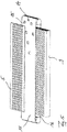
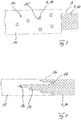
- Fig. 3 shows the partition plate 11 with its central first plate portion 14 with the recesses 15 designed as a passage opening recognizable they are arranged in the same grid as the write heads 18.
- the two second plate portions 16 On both sides of this for the sensing elements 3 permeable first plate portion 14 are the two second plate portions 16 which are completely closed and thus impermeable to the sensing elements 3.
- In the first plate region 14 are located in the embodiment diametrically opposite two recesses 23, in which engage in a manner not shown corresponding driving pins of the write head assembly 17.
- the sensor 22 detects the position of the partition plate 11 and thus also the write head assembly 17.
- a (not shown) control unit determines the target position for the sensing elements 3, located below the write head assembly 17 in the top plate 5 or in the lower plate 9 are.
- the corresponding write head 18 is activated and activated. In the exemplary embodiment, the corresponding electromagnet is energized. Otherwise, the corresponding write head 18 remains deactivated and the corresponding probe element 3 remains in the corresponding opening 10 of the lower plate 9 or falls from the corresponding Tastö réelle 4 of the upper plate 5 in the lower plate 9 and there in the corresponding position opening 10 back. If the writing head arrangement 17 and the separating plate 21 continue to move in the direction of movement 12, the second plate section 15, which is impermeable to the feeler elements 3, prevents them from falling back into the corresponding position previously lifted by the writing head arrangement 17 Touch opening 4 of the top plate 5 transported separating elements 3. In this way, train by train every desired touch point is set until the write head assembly 17 has the top plate 5 and thus the display surface 2 completely over.
- an opening window 24 is introduced. This spans all lines of the opening pattern of the top plate 5 and can extend over several columns. By means of this opening window 24, a plurality of feeler elements 3 can thus fall back from the top plate 5 into the bottom plate 9 at the same time as the display surface 2 is being overwritten.
- the writing heads 18 are positioned above the left-hand recess region. If the writing heads 18 move to the left in the direction of movement 12, they are positioned above the right-hand recess area. As a result, the write heads 18 are always in the direction of movement 12 behind the opening window 24.
- the return of the sensing elements 3 can be further improved by the return rollers 20 exert a restoring force on the sensing elements 3.
- the or each closed and impermeable to the sensing elements 3 second plate portion 16 from the recesses 14 having plate portion 14 of the partition plate 11 is separable.
- the plate portions 14, 16 are fixed in the initial state by means held by pin-hole connections holding struts 25 releasably attached to each other.
- the dimension (area) of the impermeable plate area 15 is in this case adapted to the dimension of the display surface 2 of the top plate 5 and covers virtually the entire hole pattern of the tactile openings. 4
- the display surface 2 for separate storage or entrainment from the guide device 6 can be removed and thus separated from the writing instrument 1.
- a display panel formed thereby contains as components a carrier and the top plate 5 populated with the corresponding touch elements 3 in the desired and previously produced touch point pattern and the impermeable plate region 16 of the partition plate 11.
- the display plate thus separable may also be associated with the bottom plate 9.
- the corresponding components of the display panel in the form of at least the top plate 5 and the impermeable plate portion 16 of the support plate 11 and optionally the lower plate 9 can be joined together, for example by latching or screwing.
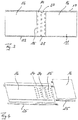
- Fig. 5 shows an embodiment of the partition plate 11 in the form of a closed separation band.
- the lower plate 9 Within this separating strip is the lower plate 9, while the upper plate 5 is above this designed as a partition partition plate 11.
- the recess area with the recesses 15 is just between the lower plate 9 and the upper plate 5, while the subsequent impermeable plate or belt area 16 is located below the lower plate 9.
- the removable variant and display panel provided for this purpose, it comprises the top plate 5 and the partition plate 11 designed as a partition plate 11 and the lower plate 9, which is practically enclosed by the separating wall-like partition plate 11.
- the Fig. 6 to 8 show variants of the arrangement and configuration of the recesses 15 along the partition plate 11.
- three recesses 15 are arranged one behind the other in the direction of movement 12 and offset relative to one another in the transverse direction 19 for this purpose.
- the corresponding arrangement of the write heads 18 is also shown.
- a again executed as a matrix with rows and columns Tastlochraster with Tastö réelleen 4 for receiving corresponding sensing elements 3 is shown.
- the distance a of the two recessed areas shown corresponds to the length L of the Tastlochrasters and thus the length of the display surface 2.
- Fig. 7 shows a momentary state of the overlap of the display surface 2 with the therein again matrix-like arranged Tastö réelleen 4 of the upper plate 5 and hereby corresponding position openings 10 of the lower plate 9.
- the opening grid here consists of a total of six lines.
- the recess region of the partition plate 11 comprises six partial rows side by side and otherwise offset successively recesses 15. Recognizable aligns each of the recesses 15 with a tactile opening 4 or position opening 10 in each case one of the lines of the opening grid.
- 10 are aligned with each other and with the corresponding recess 15 in the respective row from column to column.
- each tactile opening 4 of the top plate 5 can be equipped with a probe element 3 or fall back from there over the through the openings 4 and 10 and the corresponding recess 15 formed transport channel in the lower plate 9.
- Fig. 8 shows an embodiment of the recess portion of the partition plate 11 in the form of a cut edge pattern.
- the respective write heads 18 are arranged at the symbolized by the arrows 26 positions. Their offset corresponds in the embodiment of the arrangement grid according to Fig. 7 ,
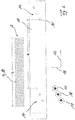
- the operation of the writing instrument 1 is in the Fig. 9a to 9e for a single Tast Vietnamese of the opening pattern of the upper and lower plates 5 and 9, respectively.
- the partition plate 11 Between the top plate 5 and the lower plate 9 is the partition plate 11, which is moved here according to the arrow shown in the direction of movement 12 from left to right.
- this plate arrangement 5, 6, 9 Above this plate arrangement 5, 6, 9 is one of the writing heads 18 of the writing head arrangement 17.
- the coupling of the corresponding writing head 18 to the separating plate 11 is illustrated by a connecting line 27.
- a cover 28 on the top plate 5 can be seen.
- the divider plate 11 between the top plate 5 and the bottom plate 9 allows a transport channel between a positional opening 10 of the bottom plate only at certain locations where there is a recess 15 in the partition plate 11 9 and a corresponding tactile opening 4 of the top plate 5.
- the corresponding, corresponding to this row or row of Tast Vietnameserasters write head 18 is always located above the recess 15th
- a probe element 3 is arranged in a corresponding tactile opening 4 of the top plate 5 and is secured there from the opaque plate portion 16 of the partition plate against falling back into the lower plate 9, while there two further probe elements 3 are arranged in corresponding position openings. These can in this position of the partition plate 11th are not transported through the impermeable plate portion 16 in the corresponding Tastö réelleen 4 of the top plate 5.
- Fig. 9b shows the writing instrument 1 in a direction of movement 12 further guided position in which the corresponding write head 18 is located above the left in the drawing 4 tactile opening. In this position is also the recess 15 of synchronously with the write head 18 moving partition plate 11 in registration with this tactile opening 4. This in turn is aligned with the corresponding position opening 10 of the lower plate 9, so that a corresponding transport channel 29 for the transport, ie a lifting of the probe element 3 is made possible from the lower plate 9 via the partition plate 11 in the upper plate 5.
- Fig. 9d and 9e show the situation of the following in the direction of movement 12 transport channel 29 by there the tactile opening 4 of the upper plate 5 and the recess 15 of the partition plate 11 and the positional opening 10 of the lower plate 9 are aligned.
- the write head 18 is deactivated, so that the corresponding probe element 3 remains in the lower plate 9 and the partition plate 11 with its impermeable plate portion 16, the corresponding positional opening 10 in the course of further movement of the partition plate 11 in the direction of movement 12 closes.
- the writing instrument 1 In particular, to display a graphic, a large number of touch points are necessary.
- the opening pattern of the top and bottom plates 5 and 9 is, as usual in Braille writing, about 2.5 mm.
- the diameter of the scanning elements 3 embodied here as spheres is approximately 1.6 mm.
- the movable stylus assembly 17 includes a total of sixteen electromagnets as write heads 18, one electromagnet for each row. Since due to the comparatively large diameter of the electromagnets whose matrix-like arrangement would exceed the grid of the Tastddlingrasters, they are arranged offset.
- a write head arrangement for example, a pneumatically operated transport or write head arrangement can be provided which promotes the feeler elements 3 from the lower plate 9 into the upper plate 5 via a corresponding arrangement of suction openings.
- differently shaped feeler elements 3, for example cylindrical pins or the like, may be provided instead of the balls.
- the position openings 10 of the lower plate 9 can be provided with a diameter that is comparatively small, that is to say in particular the smallest, through openings which allow flushing of the upper plate 5 and the lower plate 9 by means of a cleaning fluid without removing the feeler elements 3.
- only a part of the partition plate 11 designed as a separating strip 11 can be made flexible or flexible.
Landscapes
- Engineering & Computer Science (AREA)
- Educational Administration (AREA)
- General Health & Medical Sciences (AREA)
- Business, Economics & Management (AREA)
- Physics & Mathematics (AREA)
- Audiology, Speech & Language Pathology (AREA)
- Health & Medical Sciences (AREA)
- Educational Technology (AREA)
- General Physics & Mathematics (AREA)
- Theoretical Computer Science (AREA)
- User Interface Of Digital Computer (AREA)
- Devices For Indicating Variable Information By Combining Individual Elements (AREA)
- Position Input By Displaying (AREA)
Claims (10)
- Instrument d'écriture (1) destiné à afficher un motif de points tactiles, perceptible de manière tactile,- pourvu d'un plan de position (8) d'un dispositif de guidage (6) d'un plateau inférieur (9) disposant d'un nombre d'orifices de position (10) disposés en forme de matrice selon une trame d'orifices en lignes et en colonnes, dans lesquels des éléments tactiles (3) sont placés de manière amovible,- pourvu d'un plan d'affichage (7) écarté à la verticale par rapport au plan de position (8) d'un plateau supérieur (5) avec un nombre d'orifices tactiles (4), dont chacun est aligné sur un orifice de position (10) correspondant du plateau inférieur (9),- pourvu d'un ensemble de têtes d'écriture (17) guidé dans la direction de déplacement en translation (12) par rapport au dispositif de support et de guidage (6), disposant d'un nombre de têtes d'écriture (18) correspondant au nombre de lignes ou à une fraction de ce dernier, lesquelles, en fonction du motif de point à afficher, convoient des éléments tactiles (3) hors du plateau inférieur (9) dans le plateau supérieur (5) et- pourvu d'un plateau séparateur (11) placé entre le plateau inférieur (9) et le plateau supérieur (5) et également guidé relativement en translation, comportant une première zone de plateau (14) laissant passer les éléments tactiles (3) avec un nombre d'évidements (15) correspondant au nombre de lignes de la trame d'orifices des orifices (4, 10) et/ou au nombre des têtes de lecture (18) ou à une fraction de celui-ci, ainsi qu'avec une deuxième zone de plateau (16) se raccordant à la première zone de plateau (14) dans la direction de déplacement (12) et ne laissant pas passer les éléments tactiles (3),- à chacune des têtes d'écriture (18) étant associé un évidement (15) dans la première zone de plateau (14) passante, de telle sorte que les évidements (15) du plateau séparateur (11) protègent le canal de transport entre les orifices (10, 4) correspondants, alignés les uns sur les autres, des plateaux inférieur et supérieur (9, 5).
- Instrument d'écriture (1) selon la revendication 1,
caractérisé en ce que dans l'ensemble de têtes d'écriture (17), au moins quelques-unes des têtes d'écriture (18) sont placées les unes derrière les autres et en décalage par lignes, dans la direction de déplacement (12). - Instrument d'écriture (1) selon la revendication 1 ou 2,
caractérisé en ce que l'ensemble de têtes d'écriture (17) est également guidé en étant déplaçable dans la direction opposée à la direction de déplacement (12) en translation. - Instrument d'écriture (1) selon l'une quelconque des revendications 1 à 3,
caractérisé en ce que de part et d'autre de la première zone de plateau (14) laissant passer les éléments tactiles (3), le plateau séparateur (11) comporte une deuxième zone de plateau (16) ne laissant pas passer les éléments tactiles (3). - Instrument d'écriture (1) selon l'une quelconque des revendications 1 à 4,
caractérisé en ce que la première zone de plateau (14) laissant passer les éléments tactiles (3) comporte une fenêtre d'orifices (24) s'étendant dans la direction transversale (19) de la direction de déplacement (12) sur au moins l'une des lignes, de préférence sur plusieurs, notamment sur toutes les lignes de la trame d'orifices des orifices tactiles et/ou de position (4, 10) et dans la direction de déplacement (12) comporte les évidements (15) avant et/ou après la fenêtre d'orifices (24) . - Instrument d'écriture (1) selon l'une quelconque des revendications 1 à 5,
caractérisé en ce que la deuxième zone de plateau (16) ne laissant pas passer les éléments tactiles (3) comporte au moins les dimensions de la trame d'orifices des orifices tactiles et/ou de position (4, 10) et est reliée de manière amovible avec la première zone de plateau (14). - Instrument d'écriture (1) selon la revendication 6,
caractérisé en ce que la deuxième zone de plateau (16), ne laissant pas passer les éléments tactiles (3), du plateau séparateur (11), en commun avec le plateau supérieur (5), de préférence en plus, en commun avec le plateau inférieur (9) est réalisée en étant amovible du dispositif de guidage (6). - Instrument d'écriture (1) selon l'une quelconque des revendications 1 à 5,
caractérisé en ce que le plateau séparateur (11) est réalisé sous la forme d'une bande séparatrice élastique souple et/ou fermée. - Instrument d'écriture (1) selon la revendication 8,
caractérisé en ce que le plateau séparateur (11) réalisé sous la forme d'une bande séparatrice élastique souple et/ou fermée, en commun avec le plateau supérieur (5), de préférence en plus, en commun avec le plateau inférieur (9) est réalisé en étant amovible du dispositif de guidage (6). - Instrument d'écriture (1) selon l'une quelconque des revendications 1 à 9,
caractérisé en ce que les évidements (15) du plateau séparateur (11) sont placés dans une trame d'évidements, laquelle correspond à la trame de placement des têtes d'écriture (18).
Applications Claiming Priority (2)
| Application Number | Priority Date | Filing Date | Title |
|---|---|---|---|
| DE102014011326.4A DE102014011326B4 (de) | 2014-07-30 | 2014-07-30 | Taktiles Schreibgerät |
| PCT/EP2015/067191 WO2016016205A1 (fr) | 2014-07-30 | 2015-07-27 | Instrument d'écriture tactile |
Publications (2)
| Publication Number | Publication Date |
|---|---|
| EP3175437A1 EP3175437A1 (fr) | 2017-06-07 |
| EP3175437B1 true EP3175437B1 (fr) | 2018-10-17 |
Family
ID=53887076
Family Applications (1)
| Application Number | Title | Priority Date | Filing Date |
|---|---|---|---|
| EP15752939.7A Not-in-force EP3175437B1 (fr) | 2014-07-30 | 2015-07-27 | Instrument d'écriture tactile |
Country Status (4)
| Country | Link |
|---|---|
| US (1) | US20170140668A1 (fr) |
| EP (1) | EP3175437B1 (fr) |
| DE (1) | DE102014011326B4 (fr) |
| WO (1) | WO2016016205A1 (fr) |
Families Citing this family (5)
| Publication number | Priority date | Publication date | Assignee | Title |
|---|---|---|---|---|
| DE102017004105B4 (de) | 2016-04-29 | 2024-04-11 | Luitpold Greiner | Magnetisch bistabiler axialsymmetrischer Linear-Aktuator mit Polkontur, Vorrichtung mit diesem und Schaltmatrix für taktile Anwendungen |
| WO2018197052A1 (fr) | 2017-04-29 | 2018-11-01 | Luitpold Greiner | Affichage tactile à actionneur linéaire axisymétrique magnétique bistable pourvu de contour de pôle et matrice de commutation et aide visuelle optique tactile correspondante |
| US20190236120A1 (en) * | 2018-01-30 | 2019-08-01 | Eric Thomas Reid | Electronic text to braille device |
| CN109407908B (zh) * | 2018-09-30 | 2020-09-04 | 清华大学 | 一种带有触觉引导功能的图形显示器及其使用方法 |
| US11645948B2 (en) * | 2020-03-10 | 2023-05-09 | Tactile Solutions, Inc. | Capture plate assembly for braille display |
Family Cites Families (22)
| Publication number | Priority date | Publication date | Assignee | Title |
|---|---|---|---|---|
| US2565608A (en) * | 1946-02-08 | 1951-08-28 | Paul W Hoff | Braille writing device |
| US3736672A (en) * | 1971-12-29 | 1973-06-05 | J Skewis | Reading machine for the blind |
| US3899839A (en) * | 1974-06-20 | 1975-08-19 | Carl J Essmann | Writing implement for persons with greatly impaired or lost eyesight |
| FR2541011A1 (fr) * | 1983-02-11 | 1984-08-17 | Cii Honeywell Bull | Dispositif pour convertir des signaux electriques representatifs de donnees en un ensemble de points saillants constituant l'image de ces donnees |
| DE3314645A1 (de) * | 1983-04-22 | 1984-10-31 | Meinzer, Karin, 3550 Marburg | Verfahren und vorrichtung zum darstellen von grafischer information, insbesondere von blindenschrift-texten |
| SE440288B (sv) * | 1984-02-20 | 1985-07-22 | Bror Allan Eriksson | Anordning for bildande av punktskriftstext |
| AT380346B (de) * | 1984-03-30 | 1986-05-12 | Siemens Ag Oesterreich | Blindenschrift-ausgabegeraet |
| AT381067B (de) * | 1985-02-20 | 1986-08-25 | Siemens Ag Oesterreich | Geraet zur darstellung abtastbarer tastschriftzeichen |
| DE8701657U1 (de) * | 1987-02-04 | 1987-06-25 | Klimek, Frank Günter, 4200 Oberhausen | Blindenschriftdisplay |
| DE3812028A1 (de) * | 1988-04-11 | 1989-10-19 | Wolfgang Nuetzel | Anzeigeflaeche fuer taktile informationen |
| SE464840B (sv) * | 1989-10-16 | 1991-06-17 | Bror Allan Eriksson | Apparat foer visning av text eller bilder |
| JPH04180083A (ja) * | 1990-11-15 | 1992-06-26 | Yoshimichi Yonezawa | 触覚画像表示装置 |
| WO1992015079A1 (fr) * | 1991-02-19 | 1992-09-03 | Caretec Ges.M.B.H. | Dispositif pour la constitution de structures superficielles variables |
| US5245744A (en) * | 1992-03-30 | 1993-09-21 | Edgerton David A | Method for placing braille letters on architectural signs |
| US5466154A (en) * | 1993-07-26 | 1995-11-14 | Thompson; James M. | Braille board with movable dot pins |
| US6776619B1 (en) * | 1999-05-19 | 2004-08-17 | United States Of America | Refreshable braille reader |
| WO2001001374A1 (fr) * | 1999-06-28 | 2001-01-04 | Tactilics, Inc. | Moniteur en braille |
| DE10127036B4 (de) * | 2001-06-02 | 2004-07-01 | Koch, Andreas | Vorrichtung und Trägerblatt zur ertastbaren punktförmigen Darstellung von grafischen Informationen sowie Verfahren zur Herstellung des Trägerblattes |
| CN1664881A (zh) * | 2005-02-28 | 2005-09-07 | 深圳市王菱科技开发有限公司 | 多功能盲文点字模板装置 |
| US7744372B1 (en) * | 2005-12-06 | 2010-06-29 | Daniel Charles Minnich | Refreshable Braille display device |
| DE102006020568A1 (de) | 2006-04-29 | 2007-10-31 | Metec Ag | Anzeigevorrichtung zur taktil erfassbaren Darstellung von Anzeigeelementen sowie Anzeigesystem mit einer solchen Anzeigevorrichtung |
| ES2397903B2 (es) * | 2011-08-05 | 2014-03-24 | Kaparazoom Slu | Pizarra de escritura y dibujo para personas ciegas o con discapacidad visual |
-
2014
- 2014-07-30 DE DE102014011326.4A patent/DE102014011326B4/de not_active Expired - Fee Related
-
2015
- 2015-07-27 WO PCT/EP2015/067191 patent/WO2016016205A1/fr not_active Ceased
- 2015-07-27 EP EP15752939.7A patent/EP3175437B1/fr not_active Not-in-force
-
2017
- 2017-01-30 US US15/419,507 patent/US20170140668A1/en not_active Abandoned
Non-Patent Citations (1)
| Title |
|---|
| None * |
Also Published As
| Publication number | Publication date |
|---|---|
| EP3175437A1 (fr) | 2017-06-07 |
| DE102014011326B4 (de) | 2016-05-25 |
| WO2016016205A1 (fr) | 2016-02-04 |
| DE102014011326A1 (de) | 2016-02-04 |
| US20170140668A1 (en) | 2017-05-18 |
Similar Documents
| Publication | Publication Date | Title |
|---|---|---|
| EP3175437B1 (fr) | Instrument d'écriture tactile | |
| DE3400093C2 (fr) | ||
| EP3405351B1 (fr) | Dispositif de marquage pour composants électriques | |
| DE3314645A1 (de) | Verfahren und vorrichtung zum darstellen von grafischer information, insbesondere von blindenschrift-texten | |
| EP0157174B1 (fr) | Dispositif pour la présentation des textes pour aveugles | |
| EP1575400B1 (fr) | Vitrine de presentation d'objets | |
| DE3328625T1 (de) | Kassette und zugehoerige vorrichtung mit einer bilddarstellungsflaeche zum zyklischen vorfuehren einer mehrzahl von bildern | |
| DE3046037A1 (de) | Textbearbeitungsgeraet | |
| DE3400094C2 (de) | Einrichtung zur Erzeugung eines taktilen Zeichenfeldes | |
| DE1209330B (de) | Signalgeber fuer eine Programmsteuerung | |
| DE102009015159B3 (de) | Ausgabeeinheit und Verfahren zur Ausgabe von fluidisch codierten Informationen | |
| DE1900163A1 (de) | Schnelldrucker | |
| EP2286999B1 (fr) | Dispositif destiné à la comparaison d'un exemplaire d'impression avec une simulation d'un produit d'impression prédéterminé | |
| DE102008020133A1 (de) | Sicherheitsanzeigeelement für binäre Information | |
| EP0189904B1 (fr) | Table traçante avec appareil à dessiner | |
| EP0116867A2 (fr) | Méthode et dispositif d'affichage de textes sur l'écran d'un terminal de traitement de textes | |
| AT502687B1 (de) | Blindenschrift-lesegerät | |
| DE1549345A1 (de) | Dateneingabevorrichtung fuer mechanische Rechenmaschinen | |
| DE3602355A1 (de) | Geraet zur darstellung abtastbarer tastschriftzeichen | |
| AT525319B1 (de) | Vorrichtung und Verfahren zur Darstellung von tastbarer Information in Form von tastbaren und nicht-tastbaren Punkten | |
| DE102019203619B3 (de) | Haltesystem mit Bildschirm zum austauschbaren Fixieren von Bauteilen und Verfahren zur Durchführung von Messungen an einem Bauteil | |
| DE102005050119B4 (de) | Hilfsmittel zur Erweiterung des Einsatzbereiches einer Tastatur eines Computers, Übersetzungsgerätes oder dergleichen | |
| DE1497707C3 (de) | Vorrichtung zur Bearbeitung von gedruckten Lernprogrammblättern | |
| DE3604981A1 (de) | Verfahren und anordnung zum darstellen von texten auf einem mehrzeilendisplay einer textstation | |
| DE1803826B2 (de) | Stiftschreibmaschine |
Legal Events
| Date | Code | Title | Description |
|---|---|---|---|
| STAA | Information on the status of an ep patent application or granted ep patent |
Free format text: STATUS: THE INTERNATIONAL PUBLICATION HAS BEEN MADE |
|
| 17P | Request for examination filed |
Effective date: 20170215 |
|
| AK | Designated contracting states |
Kind code of ref document: A1 Designated state(s): AL AT BE BG CH CY CZ DE DK EE ES FI FR GB GR HR HU IE IS IT LI LT LU LV MC MK MT NL NO PL PT RO RS SE SI SK SM TR |
|
| AX | Request for extension of the european patent |
Extension state: BA ME |
|
| PUAI | Public reference made under article 153(3) epc to a published international application that has entered the european phase |
Free format text: ORIGINAL CODE: 0009012 |
|
| STAA | Information on the status of an ep patent application or granted ep patent |
Free format text: STATUS: REQUEST FOR EXAMINATION WAS MADE |
|
| DAV | Request for validation of the european patent (deleted) | ||
| DAX | Request for extension of the european patent (deleted) | ||
| GRAP | Despatch of communication of intention to grant a patent |
Free format text: ORIGINAL CODE: EPIDOSNIGR1 |
|
| STAA | Information on the status of an ep patent application or granted ep patent |
Free format text: STATUS: GRANT OF PATENT IS INTENDED |
|
| INTG | Intention to grant announced |
Effective date: 20180604 |
|
| GRAS | Grant fee paid |
Free format text: ORIGINAL CODE: EPIDOSNIGR3 |
|
| GRAA | (expected) grant |
Free format text: ORIGINAL CODE: 0009210 |
|
| STAA | Information on the status of an ep patent application or granted ep patent |
Free format text: STATUS: THE PATENT HAS BEEN GRANTED |
|
| AK | Designated contracting states |
Kind code of ref document: B1 Designated state(s): AL AT BE BG CH CY CZ DE DK EE ES FI FR GB GR HR HU IE IS IT LI LT LU LV MC MK MT NL NO PL PT RO RS SE SI SK SM TR |
|
| REG | Reference to a national code |
Ref country code: GB Ref legal event code: FG4D Free format text: NOT ENGLISH |
|
| REG | Reference to a national code |
Ref country code: CH Ref legal event code: EP |
|
| REG | Reference to a national code |
Ref country code: IE Ref legal event code: FG4D Free format text: LANGUAGE OF EP DOCUMENT: GERMAN |
|
| REG | Reference to a national code |
Ref country code: DE Ref legal event code: R096 Ref document number: 502015006498 Country of ref document: DE Ref country code: AT Ref legal event code: REF Ref document number: 1054904 Country of ref document: AT Kind code of ref document: T Effective date: 20181115 |
|
| REG | Reference to a national code |
Ref country code: NL Ref legal event code: MP Effective date: 20181017 |
|
| REG | Reference to a national code |
Ref country code: LT Ref legal event code: MG4D |
|
| PG25 | Lapsed in a contracting state [announced via postgrant information from national office to epo] |
Ref country code: NL Free format text: LAPSE BECAUSE OF FAILURE TO SUBMIT A TRANSLATION OF THE DESCRIPTION OR TO PAY THE FEE WITHIN THE PRESCRIBED TIME-LIMIT Effective date: 20181017 |
|
| PG25 | Lapsed in a contracting state [announced via postgrant information from national office to epo] |
Ref country code: FI Free format text: LAPSE BECAUSE OF FAILURE TO SUBMIT A TRANSLATION OF THE DESCRIPTION OR TO PAY THE FEE WITHIN THE PRESCRIBED TIME-LIMIT Effective date: 20181017 Ref country code: PL Free format text: LAPSE BECAUSE OF FAILURE TO SUBMIT A TRANSLATION OF THE DESCRIPTION OR TO PAY THE FEE WITHIN THE PRESCRIBED TIME-LIMIT Effective date: 20181017 Ref country code: BG Free format text: LAPSE BECAUSE OF FAILURE TO SUBMIT A TRANSLATION OF THE DESCRIPTION OR TO PAY THE FEE WITHIN THE PRESCRIBED TIME-LIMIT Effective date: 20190117 Ref country code: HR Free format text: LAPSE BECAUSE OF FAILURE TO SUBMIT A TRANSLATION OF THE DESCRIPTION OR TO PAY THE FEE WITHIN THE PRESCRIBED TIME-LIMIT Effective date: 20181017 Ref country code: LV Free format text: LAPSE BECAUSE OF FAILURE TO SUBMIT A TRANSLATION OF THE DESCRIPTION OR TO PAY THE FEE WITHIN THE PRESCRIBED TIME-LIMIT Effective date: 20181017 Ref country code: ES Free format text: LAPSE BECAUSE OF FAILURE TO SUBMIT A TRANSLATION OF THE DESCRIPTION OR TO PAY THE FEE WITHIN THE PRESCRIBED TIME-LIMIT Effective date: 20181017 Ref country code: LT Free format text: LAPSE BECAUSE OF FAILURE TO SUBMIT A TRANSLATION OF THE DESCRIPTION OR TO PAY THE FEE WITHIN THE PRESCRIBED TIME-LIMIT Effective date: 20181017 Ref country code: NO Free format text: LAPSE BECAUSE OF FAILURE TO SUBMIT A TRANSLATION OF THE DESCRIPTION OR TO PAY THE FEE WITHIN THE PRESCRIBED TIME-LIMIT Effective date: 20190117 Ref country code: IS Free format text: LAPSE BECAUSE OF FAILURE TO SUBMIT A TRANSLATION OF THE DESCRIPTION OR TO PAY THE FEE WITHIN THE PRESCRIBED TIME-LIMIT Effective date: 20190217 |
|
| PG25 | Lapsed in a contracting state [announced via postgrant information from national office to epo] |
Ref country code: GR Free format text: LAPSE BECAUSE OF FAILURE TO SUBMIT A TRANSLATION OF THE DESCRIPTION OR TO PAY THE FEE WITHIN THE PRESCRIBED TIME-LIMIT Effective date: 20190118 Ref country code: PT Free format text: LAPSE BECAUSE OF FAILURE TO SUBMIT A TRANSLATION OF THE DESCRIPTION OR TO PAY THE FEE WITHIN THE PRESCRIBED TIME-LIMIT Effective date: 20190217 Ref country code: RS Free format text: LAPSE BECAUSE OF FAILURE TO SUBMIT A TRANSLATION OF THE DESCRIPTION OR TO PAY THE FEE WITHIN THE PRESCRIBED TIME-LIMIT Effective date: 20181017 Ref country code: AL Free format text: LAPSE BECAUSE OF FAILURE TO SUBMIT A TRANSLATION OF THE DESCRIPTION OR TO PAY THE FEE WITHIN THE PRESCRIBED TIME-LIMIT Effective date: 20181017 Ref country code: SE Free format text: LAPSE BECAUSE OF FAILURE TO SUBMIT A TRANSLATION OF THE DESCRIPTION OR TO PAY THE FEE WITHIN THE PRESCRIBED TIME-LIMIT Effective date: 20181017 |
|
| REG | Reference to a national code |
Ref country code: DE Ref legal event code: R097 Ref document number: 502015006498 Country of ref document: DE |
|
| PG25 | Lapsed in a contracting state [announced via postgrant information from national office to epo] |
Ref country code: IT Free format text: LAPSE BECAUSE OF FAILURE TO SUBMIT A TRANSLATION OF THE DESCRIPTION OR TO PAY THE FEE WITHIN THE PRESCRIBED TIME-LIMIT Effective date: 20181017 Ref country code: CZ Free format text: LAPSE BECAUSE OF FAILURE TO SUBMIT A TRANSLATION OF THE DESCRIPTION OR TO PAY THE FEE WITHIN THE PRESCRIBED TIME-LIMIT Effective date: 20181017 Ref country code: DK Free format text: LAPSE BECAUSE OF FAILURE TO SUBMIT A TRANSLATION OF THE DESCRIPTION OR TO PAY THE FEE WITHIN THE PRESCRIBED TIME-LIMIT Effective date: 20181017 |
|
| PLBE | No opposition filed within time limit |
Free format text: ORIGINAL CODE: 0009261 |
|
| STAA | Information on the status of an ep patent application or granted ep patent |
Free format text: STATUS: NO OPPOSITION FILED WITHIN TIME LIMIT |
|
| PG25 | Lapsed in a contracting state [announced via postgrant information from national office to epo] |
Ref country code: EE Free format text: LAPSE BECAUSE OF FAILURE TO SUBMIT A TRANSLATION OF THE DESCRIPTION OR TO PAY THE FEE WITHIN THE PRESCRIBED TIME-LIMIT Effective date: 20181017 Ref country code: RO Free format text: LAPSE BECAUSE OF FAILURE TO SUBMIT A TRANSLATION OF THE DESCRIPTION OR TO PAY THE FEE WITHIN THE PRESCRIBED TIME-LIMIT Effective date: 20181017 Ref country code: SK Free format text: LAPSE BECAUSE OF FAILURE TO SUBMIT A TRANSLATION OF THE DESCRIPTION OR TO PAY THE FEE WITHIN THE PRESCRIBED TIME-LIMIT Effective date: 20181017 Ref country code: SM Free format text: LAPSE BECAUSE OF FAILURE TO SUBMIT A TRANSLATION OF THE DESCRIPTION OR TO PAY THE FEE WITHIN THE PRESCRIBED TIME-LIMIT Effective date: 20181017 |
|
| 26N | No opposition filed |
Effective date: 20190718 |
|
| PG25 | Lapsed in a contracting state [announced via postgrant information from national office to epo] |
Ref country code: SI Free format text: LAPSE BECAUSE OF FAILURE TO SUBMIT A TRANSLATION OF THE DESCRIPTION OR TO PAY THE FEE WITHIN THE PRESCRIBED TIME-LIMIT Effective date: 20181017 |
|
| PG25 | Lapsed in a contracting state [announced via postgrant information from national office to epo] |
Ref country code: MC Free format text: LAPSE BECAUSE OF FAILURE TO SUBMIT A TRANSLATION OF THE DESCRIPTION OR TO PAY THE FEE WITHIN THE PRESCRIBED TIME-LIMIT Effective date: 20181017 |
|
| REG | Reference to a national code |
Ref country code: CH Ref legal event code: PL |
|
| PG25 | Lapsed in a contracting state [announced via postgrant information from national office to epo] |
Ref country code: TR Free format text: LAPSE BECAUSE OF FAILURE TO SUBMIT A TRANSLATION OF THE DESCRIPTION OR TO PAY THE FEE WITHIN THE PRESCRIBED TIME-LIMIT Effective date: 20181017 |
|
| REG | Reference to a national code |
Ref country code: BE Ref legal event code: MM Effective date: 20190731 |
|
| PGFP | Annual fee paid to national office [announced via postgrant information from national office to epo] |
Ref country code: DE Payment date: 20191223 Year of fee payment: 5 |
|
| PG25 | Lapsed in a contracting state [announced via postgrant information from national office to epo] |
Ref country code: LU Free format text: LAPSE BECAUSE OF NON-PAYMENT OF DUE FEES Effective date: 20190727 Ref country code: LI Free format text: LAPSE BECAUSE OF NON-PAYMENT OF DUE FEES Effective date: 20190731 Ref country code: CH Free format text: LAPSE BECAUSE OF NON-PAYMENT OF DUE FEES Effective date: 20190731 Ref country code: BE Free format text: LAPSE BECAUSE OF NON-PAYMENT OF DUE FEES Effective date: 20190731 |
|
| PG25 | Lapsed in a contracting state [announced via postgrant information from national office to epo] |
Ref country code: IE Free format text: LAPSE BECAUSE OF NON-PAYMENT OF DUE FEES Effective date: 20190727 |
|
| REG | Reference to a national code |
Ref country code: DE Ref legal event code: R119 Ref document number: 502015006498 Country of ref document: DE |
|
| PG25 | Lapsed in a contracting state [announced via postgrant information from national office to epo] |
Ref country code: DE Free format text: LAPSE BECAUSE OF NON-PAYMENT OF DUE FEES Effective date: 20210202 Ref country code: CY Free format text: LAPSE BECAUSE OF FAILURE TO SUBMIT A TRANSLATION OF THE DESCRIPTION OR TO PAY THE FEE WITHIN THE PRESCRIBED TIME-LIMIT Effective date: 20181017 |
|
| PG25 | Lapsed in a contracting state [announced via postgrant information from national office to epo] |
Ref country code: HU Free format text: LAPSE BECAUSE OF FAILURE TO SUBMIT A TRANSLATION OF THE DESCRIPTION OR TO PAY THE FEE WITHIN THE PRESCRIBED TIME-LIMIT; INVALID AB INITIO Effective date: 20150727 Ref country code: MT Free format text: LAPSE BECAUSE OF FAILURE TO SUBMIT A TRANSLATION OF THE DESCRIPTION OR TO PAY THE FEE WITHIN THE PRESCRIBED TIME-LIMIT Effective date: 20181017 |
|
| REG | Reference to a national code |
Ref country code: AT Ref legal event code: MM01 Ref document number: 1054904 Country of ref document: AT Kind code of ref document: T Effective date: 20200727 |
|
| PG25 | Lapsed in a contracting state [announced via postgrant information from national office to epo] |
Ref country code: AT Free format text: LAPSE BECAUSE OF NON-PAYMENT OF DUE FEES Effective date: 20200727 |
|
| PG25 | Lapsed in a contracting state [announced via postgrant information from national office to epo] |
Ref country code: MK Free format text: LAPSE BECAUSE OF FAILURE TO SUBMIT A TRANSLATION OF THE DESCRIPTION OR TO PAY THE FEE WITHIN THE PRESCRIBED TIME-LIMIT Effective date: 20181017 |
|
| PGFP | Annual fee paid to national office [announced via postgrant information from national office to epo] |
Ref country code: GB Payment date: 20230714 Year of fee payment: 9 |
|
| PGFP | Annual fee paid to national office [announced via postgrant information from national office to epo] |
Ref country code: FR Payment date: 20230714 Year of fee payment: 9 |
|
| GBPC | Gb: european patent ceased through non-payment of renewal fee |
Effective date: 20240727 |
|
| PG25 | Lapsed in a contracting state [announced via postgrant information from national office to epo] |
Ref country code: FR Free format text: LAPSE BECAUSE OF NON-PAYMENT OF DUE FEES Effective date: 20240731 |
|
| PG25 | Lapsed in a contracting state [announced via postgrant information from national office to epo] |
Ref country code: GB Free format text: LAPSE BECAUSE OF NON-PAYMENT OF DUE FEES Effective date: 20240727 |