EP3175529B1 - Système de charge de batterie de véhicule électrique - Google Patents
Système de charge de batterie de véhicule électrique Download PDFInfo
- Publication number
- EP3175529B1 EP3175529B1 EP14898738.1A EP14898738A EP3175529B1 EP 3175529 B1 EP3175529 B1 EP 3175529B1 EP 14898738 A EP14898738 A EP 14898738A EP 3175529 B1 EP3175529 B1 EP 3175529B1
- Authority
- EP
- European Patent Office
- Prior art keywords
- central
- voltage
- battery
- charging
- converters
- Prior art date
- Legal status (The legal status is an assumption and is not a legal conclusion. Google has not performed a legal analysis and makes no representation as to the accuracy of the status listed.)
- Active
Links
Images



Classifications
-
- H—ELECTRICITY
- H02—GENERATION; CONVERSION OR DISTRIBUTION OF ELECTRIC POWER
- H02J—ELECTRIC POWER NETWORKS; CIRCUIT ARRANGEMENTS OR SYSTEMS FOR SUPPLYING OR DISTRIBUTING ELECTRIC POWER; SYSTEMS FOR STORING ELECTRIC ENERGY
- H02J7/00—Circuit arrangements for charging or discharging batteries or for supplying loads from batteries
- H02J7/02—Circuit arrangements for charging or discharging batteries or for supplying loads from batteries for charging batteries from AC mains by converters
-
- B—PERFORMING OPERATIONS; TRANSPORTING
- B60—VEHICLES IN GENERAL
- B60L—PROPULSION OF ELECTRICALLY-PROPELLED VEHICLES; SUPPLYING ELECTRIC POWER FOR AUXILIARY EQUIPMENT OF ELECTRICALLY-PROPELLED VEHICLES; ELECTRODYNAMIC BRAKE SYSTEMS FOR VEHICLES IN GENERAL; MAGNETIC SUSPENSION OR LEVITATION FOR VEHICLES; MONITORING OPERATING VARIABLES OF ELECTRICALLY-PROPELLED VEHICLES; ELECTRIC SAFETY DEVICES FOR ELECTRICALLY-PROPELLED VEHICLES
- B60L53/00—Methods of charging batteries, specially adapted for electric vehicles; Charging stations or on-board charging equipment therefor; Exchange of energy storage elements in electric vehicles
- B60L53/20—Methods of charging batteries, specially adapted for electric vehicles; Charging stations or on-board charging equipment therefor; Exchange of energy storage elements in electric vehicles characterised by converters located in the vehicle
-
- H—ELECTRICITY
- H02—GENERATION; CONVERSION OR DISTRIBUTION OF ELECTRIC POWER
- H02J—ELECTRIC POWER NETWORKS; CIRCUIT ARRANGEMENTS OR SYSTEMS FOR SUPPLYING OR DISTRIBUTING ELECTRIC POWER; SYSTEMS FOR STORING ELECTRIC ENERGY
- H02J3/00—Circuit arrangements for AC mains or AC distribution networks
- H02J3/28—Arrangements for balancing of the load in networks by storage of energy
- H02J3/32—Arrangements for balancing of the load in networks by storage of energy using batteries or super capacitors with converting means
- H02J3/322—Arrangements for balancing of the load in networks by storage of energy using batteries or super capacitors with converting means the battery being on-board an electric or hybrid vehicle, e.g. vehicle to grid arrangements [V2G], power aggregation, use of the battery for network load balancing, coordinated or cooperative battery charging
-
- H—ELECTRICITY
- H02—GENERATION; CONVERSION OR DISTRIBUTION OF ELECTRIC POWER
- H02J—ELECTRIC POWER NETWORKS; CIRCUIT ARRANGEMENTS OR SYSTEMS FOR SUPPLYING OR DISTRIBUTING ELECTRIC POWER; SYSTEMS FOR STORING ELECTRIC ENERGY
- H02J7/00—Circuit arrangements for charging or discharging batteries or for supplying loads from batteries
- H02J7/50—Circuit arrangements for charging or discharging batteries or for supplying loads from batteries acting upon multiple batteries simultaneously or sequentially
-
- H—ELECTRICITY
- H02—GENERATION; CONVERSION OR DISTRIBUTION OF ELECTRIC POWER
- H02J—ELECTRIC POWER NETWORKS; CIRCUIT ARRANGEMENTS OR SYSTEMS FOR SUPPLYING OR DISTRIBUTING ELECTRIC POWER; SYSTEMS FOR STORING ELECTRIC ENERGY
- H02J7/00—Circuit arrangements for charging or discharging batteries or for supplying loads from batteries
- H02J7/70—Circuit arrangements for charging or discharging batteries or for supplying loads from batteries characterised by the mechanical construction
-
- H—ELECTRICITY
- H02—GENERATION; CONVERSION OR DISTRIBUTION OF ELECTRIC POWER
- H02M—APPARATUS FOR CONVERSION BETWEEN AC AND AC, BETWEEN AC AND DC, OR BETWEEN DC AND DC, AND FOR USE WITH MAINS OR SIMILAR POWER SUPPLY SYSTEMS; CONVERSION OF DC OR AC INPUT POWER INTO SURGE OUTPUT POWER; CONTROL OR REGULATION THEREOF
- H02M7/00—Conversion of AC power input into DC power output; Conversion of DC power input into AC power output
- H02M7/02—Conversion of AC power input into DC power output without possibility of reversal
- H02M7/04—Conversion of AC power input into DC power output without possibility of reversal by static converters
-
- H—ELECTRICITY
- H02—GENERATION; CONVERSION OR DISTRIBUTION OF ELECTRIC POWER
- H02J—ELECTRIC POWER NETWORKS; CIRCUIT ARRANGEMENTS OR SYSTEMS FOR SUPPLYING OR DISTRIBUTING ELECTRIC POWER; SYSTEMS FOR STORING ELECTRIC ENERGY
- H02J2105/00—Networks for supplying or distributing electric power characterised by their spatial reach or by the load
- H02J2105/30—Networks for supplying or distributing electric power characterised by their spatial reach or by the load the load networks being external to vehicles, i.e. exchanging power with vehicles
- H02J2105/33—Networks for supplying or distributing electric power characterised by their spatial reach or by the load the load networks being external to vehicles, i.e. exchanging power with vehicles exchanging power with road vehicles
- H02J2105/37—Networks for supplying or distributing electric power characterised by their spatial reach or by the load the load networks being external to vehicles, i.e. exchanging power with vehicles exchanging power with road vehicles exchanging power with electric vehicles [EV] or with hybrid electric vehicles [HEV]
-
- H—ELECTRICITY
- H02—GENERATION; CONVERSION OR DISTRIBUTION OF ELECTRIC POWER
- H02J—ELECTRIC POWER NETWORKS; CIRCUIT ARRANGEMENTS OR SYSTEMS FOR SUPPLYING OR DISTRIBUTING ELECTRIC POWER; SYSTEMS FOR STORING ELECTRIC ENERGY
- H02J2207/00—Details of circuit arrangements for charging or discharging batteries or supplying loads from batteries
- H02J2207/20—Charging or discharging characterised by the power electronics converter
-
- Y—GENERAL TAGGING OF NEW TECHNOLOGICAL DEVELOPMENTS; GENERAL TAGGING OF CROSS-SECTIONAL TECHNOLOGIES SPANNING OVER SEVERAL SECTIONS OF THE IPC; TECHNICAL SUBJECTS COVERED BY FORMER USPC CROSS-REFERENCE ART COLLECTIONS [XRACs] AND DIGESTS
- Y02—TECHNOLOGIES OR APPLICATIONS FOR MITIGATION OR ADAPTATION AGAINST CLIMATE CHANGE
- Y02T—CLIMATE CHANGE MITIGATION TECHNOLOGIES RELATED TO TRANSPORTATION
- Y02T10/00—Road transport of goods or passengers
- Y02T10/60—Other road transportation technologies with climate change mitigation effect
- Y02T10/70—Energy storage systems for electromobility, e.g. batteries
-
- Y—GENERAL TAGGING OF NEW TECHNOLOGICAL DEVELOPMENTS; GENERAL TAGGING OF CROSS-SECTIONAL TECHNOLOGIES SPANNING OVER SEVERAL SECTIONS OF THE IPC; TECHNICAL SUBJECTS COVERED BY FORMER USPC CROSS-REFERENCE ART COLLECTIONS [XRACs] AND DIGESTS
- Y02—TECHNOLOGIES OR APPLICATIONS FOR MITIGATION OR ADAPTATION AGAINST CLIMATE CHANGE
- Y02T—CLIMATE CHANGE MITIGATION TECHNOLOGIES RELATED TO TRANSPORTATION
- Y02T10/00—Road transport of goods or passengers
- Y02T10/60—Other road transportation technologies with climate change mitigation effect
- Y02T10/7072—Electromobility specific charging systems or methods for batteries, ultracapacitors, supercapacitors or double-layer capacitors
-
- Y—GENERAL TAGGING OF NEW TECHNOLOGICAL DEVELOPMENTS; GENERAL TAGGING OF CROSS-SECTIONAL TECHNOLOGIES SPANNING OVER SEVERAL SECTIONS OF THE IPC; TECHNICAL SUBJECTS COVERED BY FORMER USPC CROSS-REFERENCE ART COLLECTIONS [XRACs] AND DIGESTS
- Y02—TECHNOLOGIES OR APPLICATIONS FOR MITIGATION OR ADAPTATION AGAINST CLIMATE CHANGE
- Y02T—CLIMATE CHANGE MITIGATION TECHNOLOGIES RELATED TO TRANSPORTATION
- Y02T10/00—Road transport of goods or passengers
- Y02T10/80—Technologies aiming to reduce greenhouse gasses emissions common to all road transportation technologies
- Y02T10/92—Energy efficient charging or discharging systems for batteries, ultracapacitors, supercapacitors or double-layer capacitors specially adapted for vehicles
-
- Y—GENERAL TAGGING OF NEW TECHNOLOGICAL DEVELOPMENTS; GENERAL TAGGING OF CROSS-SECTIONAL TECHNOLOGIES SPANNING OVER SEVERAL SECTIONS OF THE IPC; TECHNICAL SUBJECTS COVERED BY FORMER USPC CROSS-REFERENCE ART COLLECTIONS [XRACs] AND DIGESTS
- Y02—TECHNOLOGIES OR APPLICATIONS FOR MITIGATION OR ADAPTATION AGAINST CLIMATE CHANGE
- Y02T—CLIMATE CHANGE MITIGATION TECHNOLOGIES RELATED TO TRANSPORTATION
- Y02T90/00—Enabling technologies or technologies with a potential or indirect contribution to GHG emissions mitigation
- Y02T90/10—Technologies relating to charging of electric vehicles
- Y02T90/14—Plug-in electric vehicles
Definitions
- the invention relates to the field of system for charging a battery of an electrical vehicle, and more particularly to a system for charging a battery of at least one electrical vehicle.
- EV chargers With the development of electrical vehicle (EV), EV chargers are designed and central charging stations are constructed globally for electrical vehicles.
- PCT application WO2012/119300 A1 discloses an EV charger unit. According to figure 1 of WO2012/ 119300 A1 , standard IGBT bridges are adopted in EV charger unit for AC-DC conversions, and then DC-DC converters will be used to match the desired voltage level of batteries.
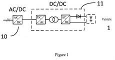
- FIG 1 is a block diagram showing a conventional EV charger unit by CHAdeMo, Technical Specification of Quick Charger for Electric Vehicle, Jan 31, 2012 .
- the EV charger unit 1 includes an AC/DC converter 10 and a DC/DC converter 11 that are linked in series.
- An EV charging station may comprise at least one EV charger unit so that it can charge the battery of at least one electrical vehicle.
- the EV charging station can be defined as two types: AC bus based station and DC bus based station.
- Figures 2 and 3 respectively show a conventional AC bus based EV charging station and a conventional DC bus based EV charging station.
- the AC bus based EV charging station 2 includes at least one EV charger unit 20 that is coupled to the AC bus bar 21.
- the AC-DC converter 200 used in each EV charger unit 20 is called distributed AC/DC converter considering that they are distributed with the EV charger units 20 in the AC bus based EV charging station 2.
- the DC bus based EV charging station 3 includes at least one EV charger unit 30 that share the same AC/DC converter 300 but each of them comprises separate DC/DC converter 301.
- the input of the DC/DC converter 301 is coupled to the output of the AC/DC converter 300 via a DC bus bar 31.
- the AC/DC converter 300 is utilized to replace the distributed AC/DC converters 200 and thus it is called central AC/DC converter.
- JP H05 276673 A discloses a battery charger for an electric vehicle having DC to DC converters connected to an output of a rectifier, wherein the converters may be connected in parallel or series.
- JP 2012 019602 A discloses a battery charger having an AC/DC converter for charging an external battery by using a power supply that is connected to a set of batteries in series or in parallel.
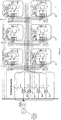
- Figure 4 illustrates an embodiment of a system for charging a battery of at least one electrical vehicle according to present invention.
- the system for charging a battery of at least one electric vehicle 4 comprises a plurality of central converters, for example four central converters 40a, 40b, 40c, 40d, at least one switch, for example six switches 41a, 41b, 41c, 41d, 41f, 41g, at least one transformer, for example six transformers 42a, 42b, 42c, 42d, 42f, 42g, at least one distributed converter, for example six distributed converters 43a, 43b, 43c, 43d, 43f, 43g, and a first controller.
- central converters for example four central converters 40a, 40b, 40c, 40d
- at least one switch for example six switches 41a, 41b, 41c, 41d, 41f, 41g
- at least one transformer for example six transformers 42a, 42b, 42c, 42d, 42f, 42g
- at least one distributed converter for example six distributed converters 43a,
- the central converter can be a two-level voltage source converter (VSC) based on IGCT or IGBT configured as a full bridge, and each of its legs has two series-connected controllable switches.
- VSC voltage source converter
- Each of the central converters 40a, 40b, 40c, 40d has an AC input electrically connectable to an external AC power supply, and the controllable switches of the central converter are used for controlling the commutation of the legs with certain switching pattern (for example, firing angle control, modulation index control, etc.) set by a second controller (not shown) to supply a output of a first DC voltage Uc1, Uc2, Uc3, Uc4 by rectifying the AC voltage from an external AC power supply.
- the second controller is connected to the central converters 40a, 40b, 40c, 40d, and can control a switching pattern of each of the central converters so that at each of the outputs of the central converters 40a, 40b, 40c, 40d, a stable first DC voltage Uc1, Uc2, Uc3, Uc4 is supplied. This is helpful for maintaining the stability of the central DC voltage and thus improving the quality of EV battery charging voltage.
- each of the central converters 40a, 40b, 40c, 40d has a DC output where the first DC voltage Uc1, Uc2, Uc3, Uc4 is supplied, and the DC outputs of the central converters 40a, 40b, 40c, 40d are serially connected. Therefore, by selecting a combination of the outputs of the central converters 40a, 40b, 40c, 40d, the central DC voltage Uc as the base for the EV battery charging voltage ranges from 0 to Uc1 + Uc2 + Uc3 + Uc4.
- the EV battery charging voltage base is 0, if the central converter 40a is selected, the EV battery charging voltage base is Uc1, if the central converters 40a, 40b are selected, the EV battery charging voltage base is Uc1 + Uc2, if the central converters 40a, 40b, 40c are selected, the EV battery charging voltage base is Uc1 + Uc2 + Uc3, and similarly if the central converters 40a, 40b, 40c, 40d are selected, the EV battery charging voltage base is Uc1 + Uc2 + Uc3 + Uc4.
- any of the central converters 40a, 40b, 40c, 40d can be selected for supplying the EV battery charging voltage base, for example, selection of the central converters 40b for supplying EV battery charging voltage base Uc2, selection of the central converters 40c for supplying EV battery charging voltage base Uc3, selection of the central converters 40d for supplying EV battery charging voltage base Uc4.
- any two or three thereof which are serially connected can also be selected for supplying the EV battery charging voltage base, for example selection of the central converters 40b, 40c for supplying EV battery charging voltage base Uc2 + Uc3, selection of the central converters 40b, 40c, 40d for supplying EV battery charging voltage base Uc2 + Uc3 + Uc4, selection of the central converters 40c, 40d for supplying EV battery charging voltage base Uc3 + Uc4.
- Each of the switches 41a, 41b, 41c, 41d, 41f, 41g has a plurality of pole terminals, throw terminals and actuator (a mechanical moving part that applies the force to contacts) being respectively electrically connected to terminals of the DC outputs of the central converters 40a, 40b, 40c, 40d.
- the switch can be mechanical switch (i.e. knife switch), chemical switch (i.e. mercury switch), light switch, electronic switch, etc. With the action of actuator, electrical connections between pole terminal and throw terminal can be formed in such kind of switch.
- the switch 41a has two pole terminals PI, P2, and five throw terminals T1, T2, T3, T4, T5 respectively electrically connected to the five terminals O1, O2, O3, O4, O5 of the DC outputs of the central converters 40a, 40b, 40c, 40d, and the other switches 41b, 41c, 41d, 41f, 41g have similar connection structure with the central converters 40a, 40b, 40c, 40d.
- the five throw terminals T1, T2, T3, T4, T5 provide the means for selection of none or one of the first DC voltage Uc1, Uc2, Uc3, Uc4 or a combination of two, three, or four of them so as to supply the EV battery charging voltage base as described above.
- the selection of none of the central converters 40a, 40b, 40c, 40d for supplying the EV battery charging voltage base can be achieved by selection of the throw terminal T1
- the selection of central converter 40a for supplying the EV battery charging voltage base can be achieved by selection of two of the throw terminals T1, T2
- the selection of central converters 40a, 40b for supplying the EV battery charging voltage base can be achieved by selection of two of the throw terminals T1, T3
- the selection of central converters 40a, 40b, 40c for supplying the EV battery charging voltage base can be achieved by selection of two of the throw terminals T1, T4
- the selection of central converters 40a, 40b, 40c, 40d for supplying the EV battery charging voltage base can be achieved by selection of two of the throw terminals T1, T5.
- any of the central converters 40a, 40b, 40c, 40d can be selected for supplying the EV battery charging voltage base, for example, the selection of central converter 40b for supplying the EV battery charging voltage base can be achieved by selection of two of the throw terminals T2, T3, the selection of central converters 40c for supplying the EV battery charging voltage base can be achieved by selection of two of the throw terminals T3, T4, the selection of central converters 40c for supplying the EV battery charging voltage base can be achieved by selection of two of the throw terminals T4, T5.
- any two or three thereof which are connected in series can also be selected for supplying the EV battery charging voltage base
- the selection of central converter 40b, 40c for supplying the EV battery charging voltage base can be achieved by selection of two of the throw terminals T2, T4
- the selection of central converters 40b, 40c, 40d for supplying the EV battery charging voltage base can be achieved by selection of two of the throw terminals T2, T5
- the selection of central converters 40c, 40d for supplying the EV battery charging voltage base can be achieved by selection of two of the throw terminals T3, T5.
- Each of the switches 41a, 41b, 41c, 41d, 41f, 41g has two pole terminals P1, P2 and an actuator A for switching between electrical connection of one of the pole terminals P1, P2 and one of the throw terminals T1, T2, T3, T4, T5 and that of the one of the pole terminals PI, P2 and another of the throw terminals T1, T2, T3, T4, T5 so as to selectively supply a voltage at a central DC output between the two pole terminals PI, P2 as a central DC voltage.
- the actuator A can electrically connect both of the pole terminals PI, P2 and the throw terminal T1, thus the central DC voltage Uc as the EV battery charging voltage base between the pole terminals PI, P2 is 0V; when the pole terminal P2 and the throw terminal T1 is electrically connected by the actuator A, the actuator A can electrically connect the pole terminal P1 and the throw terminal T2, thus the central DC voltage Uc as the EV battery charging voltage base between the pole terminal P1 and the pole terminal P2 is Uc1; when the pole terminal P2 and the throw terminal T1 is electrically connected by the actuator A, the actuator A can electrically connect the pole terminal P1 and the throw terminal T3, thus the central DC voltage Uc as the EV battery charging voltage base between the pole terminal P1 and the pole terminal P2 is Uc1+Uc2; when the pole terminal P2 and the throw terminal T1 is electrically connected by the actuator A, the actuator A can electrically connect the pole terminal P1 and the throw terminal T4, thus the central DC voltage U
- the EV battery charging voltage base (the central DC voltage Uc) can be also selected as output between one of the five throw terminals except for T1, and thus the various levels of the EV battery charging voltage base can be reached as described above.
- one of the pole terminals of the switch P1 can be arranged to be electrically connected to the throw terminal by the actuator A of the switch; and the other of the pole terminals of the switch P2 can be arranged to be electrically connected to the throw terminal directly.
- the selection of EV battery charging voltage base can also be achieved by only switching among the electrical connections of the pole terminal P1 and the throw terminals T1, T2, T3, T4, T5 by the action of the actuator A while the electrical connection involving pole terminal P2 remains unchanged.
- Each of the transformers 42a, 42b, 42c, 42d, 42f, 42g has a primary winding circuit PW and a secondary winding circuit SW, and the primary winding circuit PW can be electrically connected to the external AC power supply.
- the transformers 42a, 42b, 42c, 42d, 42f, 42g are there for the purpose of electrical isolation (or galvanic isolation) between the inputs of the central converters 40a, 40b, 40c, 40d and the distributed converters 43a, 43b, 43c, 43d, 43f, 43g and thus the input voltages of them are floating with respective to each other.
- the distributed converter 43a, 43b, 43c, 43d, 43f, 43g can supply second DC voltage Ud with a level below that of the first DC voltage Uc1, Uc2, Uc3, Uc4.
- the distributed converters 43a, 43b, 43c, 43d, 43f, 43g can also be of a full bridge, and each of its legs has two series-connected controllable switches; the controllable switches are used for controlling the commutation of the legs with certain switching pattern (for example. firing angle control, modulation index control, etc.) set by a third controller (not shown) to supply a second DC voltage Ud positive or negative.
- 6-pulse thyristor based Line Commutated Converter can be used as the distributed converters 43a, 43b, 43c, 43d, 43f, 43g.
- the thyristor based converter is used as the distributed converters 43a, 43b, 43c, 43d, 43f, 43g, not only for the large current capability, but also for blocking reversing current from the EV battery (unidirectional current characteristic of thyristor) and the larger DC voltage adjustment capabilities.
- a thyristor converter can generate either positive or negative DC voltages (depending on the operation mode: as rectifier or as inverter), which means the battery voltage in EV can be either higher or lower than the first DC voltage VI.
- the distributed converter 43a, 43b, 43c, 43d, 43f, 43g has an AC side electrically connected to the secondary winding circuit SW of the corresponding one of the transformers 42a, 42b, 42c, 42d, 42f, 42g, and it has a DC side electrically connected to the central DC output of the corresponding switch 41a, 41b, 41c, 41d, 41f, 41g in series.
- the power flows from the external AC power supply to the EV battery or vice versa.
- the third controller being connected to the corresponding one of the distributed converter 43a, 43b, 43c, 43d, 43f, 43g, can control the switching pattern thereof in consideration charging command, value of the charging current, and the value of the central DC voltage.
- Battery voltage varies during EV battery charging process.
- the third control will adjust the switching pattern continuously leading to a changed Ud. This may cause distributed converters away from designed operation point, resulting in increased power loss.
- the central converter will be maintained in a high performance operation point (high efficiency, low AC harmonic, etc). Considering the power ratio between distributed converter and central converter, total power loss is still lower comparing to existing EV charger.
- the third controller can set the switching pattern of the corresponding one of the distributed converter 43a, 43b, 43c, 43d, 43f, 43g so that it operates in rectifier mode supplying a positive voltage at its DC side if EV battery voltage is above the charging voltage during start-up, or set the start-up switching pattern of the corresponding one of the distributed converter 43a, 43b, 43c, 43d, 43f, 43g so that it operates in inverter mode supplying a negative voltage at its DC side if EV battery voltage is below the charging voltage. This renders that the EV battery charging system can reach the system dynamic balance more quickly.
- the first controller is connected to the switch 41a, 41b, 41c, 41d, 41f, 41g, so that the switch of electrical connection between the pole terminals PI, P2 and the throw terminals T1, T2, T3, T4, T5 of the respective one of the switches 41a, 41b, 41c, 41d, 41f, 41g is controlled so as to supply a combination of the central DC voltage Uc and the second DC voltage Ud as a charging voltage for the battery of the corresponding electric vehicle.
- the first controller can switch on the electrical connection between the pole terminals P1, P2 and the throw terminals T1, T2, T3, T4, T5 of the corresponding switch 41a, 41b, 41c, 41d, 41f, 41g so that the central DC voltage Uc as the EV battery charging voltage base falls under a predetermined range of the nominal charging voltage for the battery of the corresponding electric vehicle. For example, if the predetermined range of the nominal charging voltage for the battery is 0-100V, then the central DC voltage Uc needs to be selected as 0V. Accordingly, none of the central converters is selected for supplying the EV battery charging voltage base, and it follows switching on the electrical connection between the pole terminals P1, P2 and the throw terminal T1 of the switch.
- the third controller can control the distributed converter to operate in a rectifier mode.
- a combination of the central DC voltage Uc and the second DC voltage Ud falls under battery charging range of 0-100V.
- the various states are summarized as in the table I below: Table I Battery charging voltage range [V] Switching-on of throw terminal Operation mode of distributed converter Battery charging voltage range [V] Switching-on of throw terminal Operation mode of distributed converter 0 ⁇ 100 T1 Rectifier 100 ⁇ 200 T2 Inverter 500 ⁇ 600 T4 Inverter 200 ⁇ 300 T2 Rectifier 600 ⁇ 700 T4 Rectifier 300 ⁇ 400 T3 Inverter 700 ⁇ T5 Inverter 400 ⁇ 500 T3 Rectifier 800 ⁇ 900 T5 Rectifier
- the EV battery charging voltage can be supplied in the range of -100V to +900V with various switching situations of the switches 41a, 41b, 41c, 41d, 41f, 41g.
- vehicles with various nominal voltages can be charged simultaneously.
- the total number of the electrical vehicle battery that can be charged at the same time has correlation with the number of the distributed converters 43a, 43b, 43c, 43d, 43f, 43g.
- the number of the distributed converters 43a, 43b, 43c, 43d, 43f, 43g is six, and the total number of the electrical vehicle battery is six.
- the system total capacity can be distributed among the central converters 40a, 40b, 40c, 40d and the distributed converters 43a, 43b, 43c, 43d, 43f, 43g.
- the capacity for the central converters 40a, 40b, 40c, 40d may amount to 270 kW
- the capacity for each of the distributed converters 43a, 43b, 43c, 43d, 43f, 43g may amount to 5 kW.
- the total capacity of the converters according to the embodiment of present invention is lowered at 300 kW that is smaller than that of 600 kW of the conventional.
- the EV battery charging system of present invention is helpful for decreasing the converter capacity while maintaining the charging capacity. It follows that the EV battery charging system cost involving power conversion is reduced.
- Figure 5 shows a combination of the central converters and distributed converters according to an embodiment of present invention.
- the EV battery charging system according to figure 5 differs from that according to figure 4 in that: it further comprises at least one converter 45, being adapted for converting frequency of the external AC power supply to a high-frequency AC power and supplying the converted high-frequency AC power to the corresponding one of the transformers 42a, 42b, 42c, 42d, 42f, 42g.
- figure 5 only keeps two distributed converters 43d, 43f.
- the transformer v and the distributed converter 43a, 43b, 43c, 43d, 43f, 43g are operable at the high frequency.
- the characteristic of high frequency allows the usage of the transformers in less footprint/weight/cost.
- the arrow A1 shows the power flow direction where, for example, the distributed converter 43d operates in a rectifier mode, while the arrow A2 shows the power flow direction where the distributed converter 43f operates in an inverter mode.
- controllers referred by the first controller, the second controller and the third controller can be controlling modules that are distributed and implemented in different hardware or can be implemented centrally in one hardware.
Landscapes
- Engineering & Computer Science (AREA)
- Power Engineering (AREA)
- Transportation (AREA)
- Mechanical Engineering (AREA)
- Charge And Discharge Circuits For Batteries Or The Like (AREA)
- Electric Propulsion And Braking For Vehicles (AREA)
Claims (9)
- Système pour le chargement d'une batterie d'au moins un véhicule électrique, comprenant :une pluralité de convertisseurs centraux (40a-40d), chacun parmi la pluralité de convertisseurs centraux (40a-40d) ayant une entrée CA pouvant être connectée électriquement à une alimentation électrique CA externe, chacun parmi la pluralité de convertisseurs centraux (40a-40d) ayant une sortie CC, et les sorties CC de la pluralité de convertisseurs centraux (40a-40d) étant connectées en série ;au moins un commutateur, chacun des commutateurs (41a-41g) ayant une pluralité de bornes directionnelles (T1-T5) étant respectivement connectées électriquement à des bornes des sorties CC de la pluralité de convertisseurs centraux (40a-40d), chacun des commutateurs (41a-41g) ayant deux bornes polaires (P1, P2), caractérisé en ce que chacun des commutateurs (41a-41g) a un actionneur (A) destiné à commuter entre une connexion électrique d'une des bornes polaires (P1, P2) et d'une de la pluralité de bornes directionnelles (T1-T5) et celle de celle parmi les bornes polaires (P1, P2) et d'une autre parmi la pluralité de bornes directionnelles (T1-T5) de façon à alimenter de façon sélective une tension à une sortie CC centrale entre les deux bornes polaires (P1, P2) en tant que tension CC centrale ;au moins un transformateur, chacun des transformateurs (42a-42g) ayant un circuit d'enroulement primaire et un circuit d'enroulement secondaire, et le circuit d'enroulement primaire étant électriquement connecté à l'alimentation électrique CA externe ;au moins un convertisseur distribué destiné à alimenter au moins une tension CC répartie avec un niveau inférieur à celui du convertisseur central, chacun des convertisseurs distribués (43a-43g) ayant un côté CA électriquement connecté au circuit d'enroulement secondaire de celui correspondant parmi les transformateurs (42a-42g), chacun des convertisseurs distribués (43a-43g) ayant un côté CC électriquement connecté à la sortie CC centrale du commutateur correspondant dans la série ; etun premier contrôleur connecté à l'au moins un commutateur, de sorte que l'actionneur (A) de connexion électrique entre la borne polaire et la pluralité de bornes directionnelles (T1-T5) de celui respectif parmi l'au moins un commutateur (41a-41g) est commandé de façon à alimenter une combinaison de la tension CC centrale et de la tension CC répartie en tant que tension de charge pour la batterie du véhicule électrique correspondant.
- Système pour le chargement d'une batterie d'au moins un véhicule électrique selon la revendication 1, dans lequel :l'une des bornes polaires (P1, P2) du commutateur est agencée pour être électriquement connectée à la borne directionnelle par l'actionneur (A) du commutateur ; etl'autre des bornes polaires (P1, P2) du commutateur est agencée pour être électriquement connectée à la borne directionnelle directement.
- Système pour le chargement d'une batterie d'au moins un véhicule électrique selon la revendication 1, dans lequel :
l'une et l'autre des bornes polaires (P1, P2) du commutateur sont agencées pour être électriquement connectées aux bornes directionnelles (T1-T5) du commutateur par l'actionneur (A) du commutateur. - Système pour le chargement d'une batterie d'au moins un véhicule électrique selon la revendication 1, comprenant en outre :
un deuxième contrôleur connecté à la pluralité de convertisseurs centraux, étant adapté pour commander un motif de commutation de chacun parmi la pluralité de convertisseurs centraux de sorte qu'au niveau de chacune des sorties de la pluralité de convertisseurs centraux, une tension CC stable est alimentée. - Système pour le chargement d'une batterie d'au moins un véhicule électrique selon la revendication 1 ou 2, dans lequel :
le premier contrôleur est adapté en outre pour commander l'action de l'actionneur (A) du commutateur correspondant de sorte que la tension CC centrale descend sous une plage prédéterminée de la tension de charge nominale pour la batterie du véhicule électrique correspondant. - Système pour le chargement d'une batterie d'au moins un véhicule électrique selon la revendication 1 ou 2, comprenant en outre :au moins un convertisseur, étant adapté pour convertir la fréquence de l'alimentation électrique CA externe à une alimentation CA a haute fréquence et alimenter l'alimentation CA a haute fréquence convertie vers celui correspondant parmi l'au moins un transformateur (42a-42g) ;dans lequel :
le transformateur et le convertisseur distribué sont opérationnels à la haute fréquence. - Système pour le chargement d'une batterie d'au moins un véhicule électrique selon la revendication 1 ou 2, comprenant en outre :
au moins un troisième contrôleur connecté à celui correspondant parmi l'au moins un convertisseur distribué, étant adapté pour commander un motif de commutation de celui correspondant parmi l'au moins un convertisseur distribué en considérant la commande de chargement, la valeur du courant de chargement et la tension CC centrale. - Système pour le chargement d'une batterie d'au moins un véhicule électrique selon la revendication 7, dans lequel :
l'au moins un troisième contrôleur est adapté en outre pour régler le motif de commutation de celui correspondant de l'au moins un convertisseur distribué de sorte qu'il fonctionne en mode redresseur alimentant une tension positive au niveau de son côté CC si la tension de batterie de VE est supérieure à la tension de charge pendant le démarrage. - Système pour le chargement d'une batterie d'au moins un véhicule électrique selon la revendication 7, dans lequel :
l'au moins un troisième contrôleur est adapté en outre pour régler le motif de commutation de celui correspondant de l'au moins un convertisseur distribué de sorte qu'il fonctionne en mode onduleur alimentant une tension négative au niveau de son côté CC si la tension de batterie de VE est inférieure à la tension de charge pendant le démarrage.
Applications Claiming Priority (1)
| Application Number | Priority Date | Filing Date | Title |
|---|---|---|---|
| PCT/CN2014/083420 WO2016015281A1 (fr) | 2014-07-31 | 2014-07-31 | Système de charge de batterie de véhicule électrique |
Publications (3)
| Publication Number | Publication Date |
|---|---|
| EP3175529A1 EP3175529A1 (fr) | 2017-06-07 |
| EP3175529A4 EP3175529A4 (fr) | 2017-12-27 |
| EP3175529B1 true EP3175529B1 (fr) | 2019-01-09 |
Family
ID=55216637
Family Applications (1)
| Application Number | Title | Priority Date | Filing Date |
|---|---|---|---|
| EP14898738.1A Active EP3175529B1 (fr) | 2014-07-31 | 2014-07-31 | Système de charge de batterie de véhicule électrique |
Country Status (3)
| Country | Link |
|---|---|
| US (1) | US10179515B2 (fr) |
| EP (1) | EP3175529B1 (fr) |
| WO (1) | WO2016015281A1 (fr) |
Cited By (8)
| Publication number | Priority date | Publication date | Assignee | Title |
|---|---|---|---|---|
| WO2023046399A1 (fr) | 2021-09-27 | 2023-03-30 | KEBA Energy Automation GmbH | Câble de charge pour une station de charge, station de charge, système comprenant une pluralité de stations de charge et procédé de fonctionnement d'une station de charge |
| DE102021124860A1 (de) | 2021-09-27 | 2023-03-30 | KEBA Energy Automation GmbH | Ladestation und System mit einer Mehrzahl von Ladestationen |
| WO2023046417A1 (fr) | 2021-09-27 | 2023-03-30 | KEBA Energy Automation GmbH | Câble de charge pour une station de charge, station de charge, système comprenant une pluralité de stations de charge et procédé de fonctionnement d'une station de charge |
| DE102021124930A1 (de) | 2021-09-27 | 2023-03-30 | KEBA Energy Automation GmbH | Ladekabel für eine ladestation, ladestation, system mit einer mehrzahl von ladestationen und verfahren zum betreiben einer ladestation |
| DE102021124917A1 (de) | 2021-09-27 | 2023-03-30 | KEBA Energy Automation GmbH | Ladekabel für eine ladestation, ladestation, system mit einer mehrzahl von ladestationen und verfahren zum betreiben einer ladestation |
| DE102021124894A1 (de) | 2021-09-27 | 2023-03-30 | KEBA Energy Automation GmbH | Ladekabel für eine Ladestation, Ladestation, System mit einer Mehrzahl von Ladestationen und Verfahren zum Betreiben einer Ladestation |
| DE102021124937A1 (de) | 2021-09-27 | 2023-03-30 | KEBA Energy Automation GmbH | Ladekabel für eine ladestation, ladestation, system mit einer mehrzahl von ladestationen und verfahren zum betreiben einer ladestation |
| DE102023116528A1 (de) * | 2023-06-23 | 2024-12-24 | KEBA Energy Automation GmbH | Ladestation und Verfahren zum Betreiben einer Ladestation |
Families Citing this family (6)
| Publication number | Priority date | Publication date | Assignee | Title |
|---|---|---|---|---|
| DE102016123923A1 (de) * | 2016-12-09 | 2018-06-14 | Dr. Ing. H.C. F. Porsche Aktiengesellschaft | Ladevorrichtung |
| DE102017108562A1 (de) * | 2017-04-21 | 2018-10-25 | Wobben Properties Gmbh | Ladestation zum Laden mehrerer Elektrofahrzeuge, insbesondere Elektroautomobile |
| US11349332B2 (en) * | 2018-05-08 | 2022-05-31 | Honda Motor Co., Ltd. | Battery energy storage system |
| EP3920356A1 (fr) * | 2020-06-02 | 2021-12-08 | ABB Schweiz AG | Station de recharge de véhicule électrique |
| US11837905B2 (en) * | 2021-05-25 | 2023-12-05 | Cyberswitchingpatents, Llc | Battery charger system |
| US20240146088A1 (en) * | 2021-06-10 | 2024-05-02 | Enatel | Motive power electrical energy storage systems and methods |
Family Cites Families (11)
| Publication number | Priority date | Publication date | Assignee | Title |
|---|---|---|---|---|
| JP3214044B2 (ja) * | 1992-03-27 | 2001-10-02 | 株式会社明電舎 | 充電装置 |
| US7057376B2 (en) * | 2004-01-14 | 2006-06-06 | Vanner, Inc. | Power management system for vehicles |
| CN1877952A (zh) * | 2005-06-10 | 2006-12-13 | 北京机电研究所 | 电动汽车充电站 |
| JP2012019602A (ja) * | 2010-07-07 | 2012-01-26 | Jfe Engineering Corp | 急速充電方法及び装置 |
| WO2012037722A1 (fr) * | 2010-09-21 | 2012-03-29 | Abb Research Ltd. | Système d'automatisation de charge de véhicule électrique et procédé de commande associé |
| CN102025182B (zh) * | 2010-11-30 | 2012-10-31 | 梁一桥 | 多功能电动汽车动力电池组模块化充放电系统 |
| EP2641322B1 (fr) * | 2011-02-08 | 2016-04-13 | Siemens Aktiengesellschaft | Système d'alimentation d'energie avec un convertisseur multiphase de matrice et un procede pour son operation |
| WO2012119300A1 (fr) * | 2011-03-07 | 2012-09-13 | Abb Research Ltd. | Système de commande électrique actif et réactif hiérarchique dans des stations de chargement de véhicule électrique, et son procédé |
| FR2987181B1 (fr) * | 2012-02-17 | 2015-09-04 | Alstom Technology Ltd | Dispositif de conversion electrique ac/dc autorisant une recuperation d'energie et une gestion des courts-circuits cote continu |
| CN103219764A (zh) * | 2013-04-03 | 2013-07-24 | 湖南大学 | 一种电动汽车车载充电系统及其充电控制方法 |
| CN103795132A (zh) * | 2014-02-28 | 2014-05-14 | 东北电力大学 | 基于高频隔离技术的模块化多端口型电动汽车快速充电站 |
-
2014
- 2014-07-31 EP EP14898738.1A patent/EP3175529B1/fr active Active
- 2014-07-31 WO PCT/CN2014/083420 patent/WO2016015281A1/fr not_active Ceased
-
2016
- 2016-06-07 US US15/175,733 patent/US10179515B2/en active Active
Non-Patent Citations (1)
| Title |
|---|
| None * |
Cited By (12)
| Publication number | Priority date | Publication date | Assignee | Title |
|---|---|---|---|---|
| WO2023046399A1 (fr) | 2021-09-27 | 2023-03-30 | KEBA Energy Automation GmbH | Câble de charge pour une station de charge, station de charge, système comprenant une pluralité de stations de charge et procédé de fonctionnement d'une station de charge |
| DE102021124860A1 (de) | 2021-09-27 | 2023-03-30 | KEBA Energy Automation GmbH | Ladestation und System mit einer Mehrzahl von Ladestationen |
| WO2023046417A1 (fr) | 2021-09-27 | 2023-03-30 | KEBA Energy Automation GmbH | Câble de charge pour une station de charge, station de charge, système comprenant une pluralité de stations de charge et procédé de fonctionnement d'une station de charge |
| DE102021124869A1 (de) | 2021-09-27 | 2023-03-30 | KEBA Energy Automation GmbH | Ladekabel für eine Ladestation, Ladestation, System mit einer Mehrzahl von Ladestationen und Verfahren zum Betreiben einer Ladestation |
| DE102021124888A1 (de) | 2021-09-27 | 2023-03-30 | KEBA Energy Automation GmbH | Ladekabel für eine Ladestation, Ladestation, System mit einer Mehrzahl von Ladestationen und Verfahren zum Betreiben einer Ladestation |
| DE102021124930A1 (de) | 2021-09-27 | 2023-03-30 | KEBA Energy Automation GmbH | Ladekabel für eine ladestation, ladestation, system mit einer mehrzahl von ladestationen und verfahren zum betreiben einer ladestation |
| DE102021124917A1 (de) | 2021-09-27 | 2023-03-30 | KEBA Energy Automation GmbH | Ladekabel für eine ladestation, ladestation, system mit einer mehrzahl von ladestationen und verfahren zum betreiben einer ladestation |
| WO2023046397A1 (fr) | 2021-09-27 | 2023-03-30 | KEBA Energy Automation GmbH | Station de charge et système comprenant une pluralité de stations de charge |
| WO2023046393A1 (fr) | 2021-09-27 | 2023-03-30 | KEBA Energy Automation GmbH | Câble de charge pour une station de charge, station de charge, système comprenant une pluralité de stations de charge et procédé de fonctionnement d'une station de charge |
| DE102021124894A1 (de) | 2021-09-27 | 2023-03-30 | KEBA Energy Automation GmbH | Ladekabel für eine Ladestation, Ladestation, System mit einer Mehrzahl von Ladestationen und Verfahren zum Betreiben einer Ladestation |
| DE102021124937A1 (de) | 2021-09-27 | 2023-03-30 | KEBA Energy Automation GmbH | Ladekabel für eine ladestation, ladestation, system mit einer mehrzahl von ladestationen und verfahren zum betreiben einer ladestation |
| DE102023116528A1 (de) * | 2023-06-23 | 2024-12-24 | KEBA Energy Automation GmbH | Ladestation und Verfahren zum Betreiben einer Ladestation |
Also Published As
| Publication number | Publication date |
|---|---|
| US20160362012A1 (en) | 2016-12-15 |
| US10179515B2 (en) | 2019-01-15 |
| EP3175529A4 (fr) | 2017-12-27 |
| WO2016015281A1 (fr) | 2016-02-04 |
| EP3175529A1 (fr) | 2017-06-07 |
Similar Documents
| Publication | Publication Date | Title |
|---|---|---|
| EP3175529B1 (fr) | Système de charge de batterie de véhicule électrique | |
| US11088550B2 (en) | Vehicle having an energy storage element | |
| CN101657946B (zh) | 三相大功率不间断电源 | |
| JP7561273B2 (ja) | 電力網 | |
| EP3121949A1 (fr) | Convertisseur de puissance | |
| JP2022111074A (ja) | 電力変換システム及びその制御方法 | |
| US10873254B2 (en) | Electrical circuit for zero-voltage soft-switching in DC-DC converter under all load conditions | |
| US20230278442A1 (en) | Traction Network for a Motor Vehicle | |
| CN109088462B (zh) | 一种含交流模块的电池主动均衡装置 | |
| US12542497B2 (en) | Power conversion device, power conversion system, and method for controlling power conversion device | |
| CN205565845U (zh) | 用于给至少一个电动汽车的电池充电的系统 | |
| CN116488224A (zh) | 多端口交直流混合变流装置及多端交直流混合系统 | |
| US12143001B2 (en) | Power supply device | |
| KR20200017947A (ko) | Dc-dc 컨버터 기능을 포함하는 전압 밸런서 | |
| KR20130053794A (ko) | 릴레이를 이용한 가변 배터리 충전기 | |
| EP4282062A1 (fr) | Convertisseur de puissance bidirectionnel | |
| US11018600B2 (en) | Multilevel converter for the control and transmission of electrical energy | |
| KR101849001B1 (ko) | 고전압 대전류 전력 변환 장치 | |
| EP4369577A1 (fr) | Convertisseur de puissance bidirectionnel | |
| US20250368058A1 (en) | Multiport converter for auxiliary power supply | |
| US12567805B2 (en) | Voltage converter with wide range output | |
| CN217037067U (zh) | 一种具有串并联切换的直流电源 | |
| KR101217060B1 (ko) | Scr을 이용한 가변 배터리 충전기 | |
| Chamarthi et al. | A nine level inverter based grid connected solar PV system with voltage boosting | |
| US11671016B2 (en) | Multi-phase direct voltage converter for a fuel cell stack |
Legal Events
| Date | Code | Title | Description |
|---|---|---|---|
| 17P | Request for examination filed |
Effective date: 20160323 |
|
| AK | Designated contracting states |
Kind code of ref document: A1 Designated state(s): AL AT BE BG CH CY CZ DE DK EE ES FI FR GB GR HR HU IE IS IT LI LT LU LV MC MK MT NL NO PL PT RO RS SE SI SK SM TR |
|
| AX | Request for extension of the european patent |
Extension state: BA ME |
|
| PUAI | Public reference made under article 153(3) epc to a published international application that has entered the european phase |
Free format text: ORIGINAL CODE: 0009012 |
|
| STAA | Information on the status of an ep patent application or granted ep patent |
Free format text: STATUS: REQUEST FOR EXAMINATION WAS MADE |
|
| RAP1 | Party data changed (applicant data changed or rights of an application transferred) |
Owner name: ABB SCHWEIZ AG |
|
| DAX | Request for extension of the european patent (deleted) | ||
| RIC1 | Information provided on ipc code assigned before grant |
Ipc: H02J 7/02 20160101ALI20171113BHEP Ipc: H02J 7/00 20060101AFI20171113BHEP Ipc: H02M 7/04 20060101ALI20171113BHEP Ipc: B60L 11/18 20060101ALI20171113BHEP |
|
| A4 | Supplementary search report drawn up and despatched |
Effective date: 20171127 |
|
| GRAP | Despatch of communication of intention to grant a patent |
Free format text: ORIGINAL CODE: EPIDOSNIGR1 |
|
| STAA | Information on the status of an ep patent application or granted ep patent |
Free format text: STATUS: GRANT OF PATENT IS INTENDED |
|
| INTG | Intention to grant announced |
Effective date: 20180820 |
|
| GRAS | Grant fee paid |
Free format text: ORIGINAL CODE: EPIDOSNIGR3 |
|
| GRAA | (expected) grant |
Free format text: ORIGINAL CODE: 0009210 |
|
| STAA | Information on the status of an ep patent application or granted ep patent |
Free format text: STATUS: THE PATENT HAS BEEN GRANTED |
|
| AK | Designated contracting states |
Kind code of ref document: B1 Designated state(s): AL AT BE BG CH CY CZ DE DK EE ES FI FR GB GR HR HU IE IS IT LI LT LU LV MC MK MT NL NO PL PT RO RS SE SI SK SM TR |
|
| REG | Reference to a national code |
Ref country code: GB Ref legal event code: FG4D |
|
| REG | Reference to a national code |
Ref country code: CH Ref legal event code: EP Ref country code: AT Ref legal event code: REF Ref document number: 1088542 Country of ref document: AT Kind code of ref document: T Effective date: 20190115 |
|
| REG | Reference to a national code |
Ref country code: IE Ref legal event code: FG4D |
|
| REG | Reference to a national code |
Ref country code: DE Ref legal event code: R096 Ref document number: 602014039850 Country of ref document: DE |
|
| REG | Reference to a national code |
Ref country code: NL Ref legal event code: MP Effective date: 20190109 |
|
| REG | Reference to a national code |
Ref country code: LT Ref legal event code: MG4D |
|
| PG25 | Lapsed in a contracting state [announced via postgrant information from national office to epo] |
Ref country code: NL Free format text: LAPSE BECAUSE OF FAILURE TO SUBMIT A TRANSLATION OF THE DESCRIPTION OR TO PAY THE FEE WITHIN THE PRESCRIBED TIME-LIMIT Effective date: 20190109 |
|
| REG | Reference to a national code |
Ref country code: AT Ref legal event code: MK05 Ref document number: 1088542 Country of ref document: AT Kind code of ref document: T Effective date: 20190109 |
|
| PG25 | Lapsed in a contracting state [announced via postgrant information from national office to epo] |
Ref country code: ES Free format text: LAPSE BECAUSE OF FAILURE TO SUBMIT A TRANSLATION OF THE DESCRIPTION OR TO PAY THE FEE WITHIN THE PRESCRIBED TIME-LIMIT Effective date: 20190109 Ref country code: LT Free format text: LAPSE BECAUSE OF FAILURE TO SUBMIT A TRANSLATION OF THE DESCRIPTION OR TO PAY THE FEE WITHIN THE PRESCRIBED TIME-LIMIT Effective date: 20190109 Ref country code: PL Free format text: LAPSE BECAUSE OF FAILURE TO SUBMIT A TRANSLATION OF THE DESCRIPTION OR TO PAY THE FEE WITHIN THE PRESCRIBED TIME-LIMIT Effective date: 20190109 Ref country code: SE Free format text: LAPSE BECAUSE OF FAILURE TO SUBMIT A TRANSLATION OF THE DESCRIPTION OR TO PAY THE FEE WITHIN THE PRESCRIBED TIME-LIMIT Effective date: 20190109 Ref country code: NO Free format text: LAPSE BECAUSE OF FAILURE TO SUBMIT A TRANSLATION OF THE DESCRIPTION OR TO PAY THE FEE WITHIN THE PRESCRIBED TIME-LIMIT Effective date: 20190409 Ref country code: PT Free format text: LAPSE BECAUSE OF FAILURE TO SUBMIT A TRANSLATION OF THE DESCRIPTION OR TO PAY THE FEE WITHIN THE PRESCRIBED TIME-LIMIT Effective date: 20190509 Ref country code: FI Free format text: LAPSE BECAUSE OF FAILURE TO SUBMIT A TRANSLATION OF THE DESCRIPTION OR TO PAY THE FEE WITHIN THE PRESCRIBED TIME-LIMIT Effective date: 20190109 |
|
| PG25 | Lapsed in a contracting state [announced via postgrant information from national office to epo] |
Ref country code: HR Free format text: LAPSE BECAUSE OF FAILURE TO SUBMIT A TRANSLATION OF THE DESCRIPTION OR TO PAY THE FEE WITHIN THE PRESCRIBED TIME-LIMIT Effective date: 20190109 Ref country code: LV Free format text: LAPSE BECAUSE OF FAILURE TO SUBMIT A TRANSLATION OF THE DESCRIPTION OR TO PAY THE FEE WITHIN THE PRESCRIBED TIME-LIMIT Effective date: 20190109 Ref country code: IS Free format text: LAPSE BECAUSE OF FAILURE TO SUBMIT A TRANSLATION OF THE DESCRIPTION OR TO PAY THE FEE WITHIN THE PRESCRIBED TIME-LIMIT Effective date: 20190509 Ref country code: BG Free format text: LAPSE BECAUSE OF FAILURE TO SUBMIT A TRANSLATION OF THE DESCRIPTION OR TO PAY THE FEE WITHIN THE PRESCRIBED TIME-LIMIT Effective date: 20190409 Ref country code: RS Free format text: LAPSE BECAUSE OF FAILURE TO SUBMIT A TRANSLATION OF THE DESCRIPTION OR TO PAY THE FEE WITHIN THE PRESCRIBED TIME-LIMIT Effective date: 20190109 Ref country code: GR Free format text: LAPSE BECAUSE OF FAILURE TO SUBMIT A TRANSLATION OF THE DESCRIPTION OR TO PAY THE FEE WITHIN THE PRESCRIBED TIME-LIMIT Effective date: 20190410 |
|
| REG | Reference to a national code |
Ref country code: DE Ref legal event code: R097 Ref document number: 602014039850 Country of ref document: DE |
|
| PG25 | Lapsed in a contracting state [announced via postgrant information from national office to epo] |
Ref country code: SK Free format text: LAPSE BECAUSE OF FAILURE TO SUBMIT A TRANSLATION OF THE DESCRIPTION OR TO PAY THE FEE WITHIN THE PRESCRIBED TIME-LIMIT Effective date: 20190109 Ref country code: RO Free format text: LAPSE BECAUSE OF FAILURE TO SUBMIT A TRANSLATION OF THE DESCRIPTION OR TO PAY THE FEE WITHIN THE PRESCRIBED TIME-LIMIT Effective date: 20190109 Ref country code: CZ Free format text: LAPSE BECAUSE OF FAILURE TO SUBMIT A TRANSLATION OF THE DESCRIPTION OR TO PAY THE FEE WITHIN THE PRESCRIBED TIME-LIMIT Effective date: 20190109 Ref country code: AL Free format text: LAPSE BECAUSE OF FAILURE TO SUBMIT A TRANSLATION OF THE DESCRIPTION OR TO PAY THE FEE WITHIN THE PRESCRIBED TIME-LIMIT Effective date: 20190109 Ref country code: DK Free format text: LAPSE BECAUSE OF FAILURE TO SUBMIT A TRANSLATION OF THE DESCRIPTION OR TO PAY THE FEE WITHIN THE PRESCRIBED TIME-LIMIT Effective date: 20190109 Ref country code: IT Free format text: LAPSE BECAUSE OF FAILURE TO SUBMIT A TRANSLATION OF THE DESCRIPTION OR TO PAY THE FEE WITHIN THE PRESCRIBED TIME-LIMIT Effective date: 20190109 Ref country code: EE Free format text: LAPSE BECAUSE OF FAILURE TO SUBMIT A TRANSLATION OF THE DESCRIPTION OR TO PAY THE FEE WITHIN THE PRESCRIBED TIME-LIMIT Effective date: 20190109 Ref country code: AT Free format text: LAPSE BECAUSE OF FAILURE TO SUBMIT A TRANSLATION OF THE DESCRIPTION OR TO PAY THE FEE WITHIN THE PRESCRIBED TIME-LIMIT Effective date: 20190109 |
|
| PLBE | No opposition filed within time limit |
Free format text: ORIGINAL CODE: 0009261 |
|
| STAA | Information on the status of an ep patent application or granted ep patent |
Free format text: STATUS: NO OPPOSITION FILED WITHIN TIME LIMIT |
|
| PG25 | Lapsed in a contracting state [announced via postgrant information from national office to epo] |
Ref country code: SM Free format text: LAPSE BECAUSE OF FAILURE TO SUBMIT A TRANSLATION OF THE DESCRIPTION OR TO PAY THE FEE WITHIN THE PRESCRIBED TIME-LIMIT Effective date: 20190109 |
|
| 26N | No opposition filed |
Effective date: 20191010 |
|
| PG25 | Lapsed in a contracting state [announced via postgrant information from national office to epo] |
Ref country code: SI Free format text: LAPSE BECAUSE OF FAILURE TO SUBMIT A TRANSLATION OF THE DESCRIPTION OR TO PAY THE FEE WITHIN THE PRESCRIBED TIME-LIMIT Effective date: 20190109 Ref country code: MC Free format text: LAPSE BECAUSE OF FAILURE TO SUBMIT A TRANSLATION OF THE DESCRIPTION OR TO PAY THE FEE WITHIN THE PRESCRIBED TIME-LIMIT Effective date: 20190109 |
|
| REG | Reference to a national code |
Ref country code: CH Ref legal event code: PL |
|
| PG25 | Lapsed in a contracting state [announced via postgrant information from national office to epo] |
Ref country code: TR Free format text: LAPSE BECAUSE OF FAILURE TO SUBMIT A TRANSLATION OF THE DESCRIPTION OR TO PAY THE FEE WITHIN THE PRESCRIBED TIME-LIMIT Effective date: 20190109 |
|
| REG | Reference to a national code |
Ref country code: BE Ref legal event code: MM Effective date: 20190731 |
|
| PG25 | Lapsed in a contracting state [announced via postgrant information from national office to epo] |
Ref country code: CH Free format text: LAPSE BECAUSE OF NON-PAYMENT OF DUE FEES Effective date: 20190731 Ref country code: LI Free format text: LAPSE BECAUSE OF NON-PAYMENT OF DUE FEES Effective date: 20190731 Ref country code: BE Free format text: LAPSE BECAUSE OF NON-PAYMENT OF DUE FEES Effective date: 20190731 Ref country code: LU Free format text: LAPSE BECAUSE OF NON-PAYMENT OF DUE FEES Effective date: 20190731 |
|
| PG25 | Lapsed in a contracting state [announced via postgrant information from national office to epo] |
Ref country code: IE Free format text: LAPSE BECAUSE OF NON-PAYMENT OF DUE FEES Effective date: 20190731 |
|
| PG25 | Lapsed in a contracting state [announced via postgrant information from national office to epo] |
Ref country code: CY Free format text: LAPSE BECAUSE OF FAILURE TO SUBMIT A TRANSLATION OF THE DESCRIPTION OR TO PAY THE FEE WITHIN THE PRESCRIBED TIME-LIMIT Effective date: 20190109 |
|
| PG25 | Lapsed in a contracting state [announced via postgrant information from national office to epo] |
Ref country code: MT Free format text: LAPSE BECAUSE OF FAILURE TO SUBMIT A TRANSLATION OF THE DESCRIPTION OR TO PAY THE FEE WITHIN THE PRESCRIBED TIME-LIMIT Effective date: 20190109 Ref country code: HU Free format text: LAPSE BECAUSE OF FAILURE TO SUBMIT A TRANSLATION OF THE DESCRIPTION OR TO PAY THE FEE WITHIN THE PRESCRIBED TIME-LIMIT; INVALID AB INITIO Effective date: 20140731 |
|
| PG25 | Lapsed in a contracting state [announced via postgrant information from national office to epo] |
Ref country code: MK Free format text: LAPSE BECAUSE OF FAILURE TO SUBMIT A TRANSLATION OF THE DESCRIPTION OR TO PAY THE FEE WITHIN THE PRESCRIBED TIME-LIMIT Effective date: 20190109 |
|
| REG | Reference to a national code |
Ref country code: DE Ref legal event code: R081 Ref document number: 602014039850 Country of ref document: DE Owner name: ABB E-MOBILITY B.V., NL Free format text: FORMER OWNER: ABB SCHWEIZ AG, BADEN, CH Ref country code: DE Ref legal event code: R082 Ref document number: 602014039850 Country of ref document: DE Representative=s name: DENNEMEYER & ASSOCIATES S.A., DE |
|
| REG | Reference to a national code |
Ref country code: GB Ref legal event code: 732E Free format text: REGISTERED BETWEEN 20230706 AND 20230712 |
|
| PGFP | Annual fee paid to national office [announced via postgrant information from national office to epo] |
Ref country code: DE Payment date: 20250722 Year of fee payment: 12 |
|
| PGFP | Annual fee paid to national office [announced via postgrant information from national office to epo] |
Ref country code: GB Payment date: 20250722 Year of fee payment: 12 |
|
| PGFP | Annual fee paid to national office [announced via postgrant information from national office to epo] |
Ref country code: FR Payment date: 20250725 Year of fee payment: 12 |