EP3175751B1 - Plaque conductrice de chaleur et récipient de cuisson la comprenant - Google Patents
Plaque conductrice de chaleur et récipient de cuisson la comprenant Download PDFInfo
- Publication number
- EP3175751B1 EP3175751B1 EP16201997.0A EP16201997A EP3175751B1 EP 3175751 B1 EP3175751 B1 EP 3175751B1 EP 16201997 A EP16201997 A EP 16201997A EP 3175751 B1 EP3175751 B1 EP 3175751B1
- Authority
- EP
- European Patent Office
- Prior art keywords
- region
- heat conduction
- conduction plate
- plate according
- cooking vessel
- Prior art date
- Legal status (The legal status is an assumption and is not a legal conclusion. Google has not performed a legal analysis and makes no representation as to the accuracy of the status listed.)
- Active
Links
Images


Classifications
-
- A—HUMAN NECESSITIES
- A47—FURNITURE; DOMESTIC ARTICLES OR APPLIANCES; COFFEE MILLS; SPICE MILLS; SUCTION CLEANERS IN GENERAL
- A47J—KITCHEN EQUIPMENT; COFFEE MILLS; SPICE MILLS; APPARATUS FOR MAKING BEVERAGES
- A47J27/00—Cooking-vessels
- A47J27/002—Construction of cooking-vessels; Methods or processes of manufacturing specially adapted for cooking-vessels
-
- A—HUMAN NECESSITIES
- A47—FURNITURE; DOMESTIC ARTICLES OR APPLIANCES; COFFEE MILLS; SPICE MILLS; SUCTION CLEANERS IN GENERAL
- A47J—KITCHEN EQUIPMENT; COFFEE MILLS; SPICE MILLS; APPARATUS FOR MAKING BEVERAGES
- A47J36/00—Parts, details or accessories of cooking-vessels
- A47J36/02—Selection of specific materials, e.g. heavy bottoms with copper inlay or with insulating inlay
- A47J36/027—Cooking- or baking-vessels specially adapted for use in microwave ovens; Accessories therefor
Definitions
- the present invention relates to a heat conducting plate and a cooking vessel formed therewith, particularly in the form of a pan.
- Cooking vessels are typically placed on a hob for heating food, which heats the bottom of the cooking vessel. It can happen that the bottom of the cooking vessel warps. The warpage can cause the bottom of the cooking vessel to become uneven, with the result that the support properties and, as a result, the stability of the cooking vessel and also the heat transfer between the hotplate and the floor deteriorate. As a result, on the one hand, the heat distribution within the floor becomes uneven and, on the other hand, the energy consumption required increases. This affects both the function and the ecological fingerprint.
- One aspect of the invention is a circular, oval or polygonal metal heat-conducting plate which can be used, for example, as an intermediate layer between a heating device, for example an induction or other cooker, and a cooking vessel in order to optimally transfer heat between the heating device and the cooking vessel. without there being direct contact between the cooking vessel and the heating device.
- the heat-conducting plate should not warp when heated, so that the cooking vessel rests as completely as possible on an upper side of the heat-conducting plate when the heat-conducting plate and cooking vessel base are in the heated state, and the underside of the heat-conducting plate rests as completely as possible on the heating device.
- the object of the present invention is firstly to provide a heat-conducting plate which is not planar but is shaped or pre-deformed in such a way that, when heated, good contact properties on a planar heating device and good heat transfer properties are achieved.
- this object is achieved by a heat-conducting plate according to claim 1 .
- the object of the present invention to provide a cooking vessel whose base is shaped in such a way that good support and heat transfer properties are achieved when heated.
- An improved shape is intended to ensure that the cooking vessel is particularly light, has a low heat capacity, has fast reaction times and at the same time has good heat distribution and is stable on the base at all temperatures of use without tipping over.
- this object is achieved by a cooking vessel according to claim 15 .
- the cooking vessel according to the invention comprises a base, which is formed in particular by a heat-conducting plate according to the invention and can be circular, oval or polygonal, with a peripheral edge extending upwards (away from the cooking area).
- the base has a first ring-shaped area, which runs with an underside in a support plane and which is designed to rest on a flat cooking surface on which the cooking vessel is placed during operation, a second ring-like area in the shape of a truncated cone or truncated pyramid is enclosed by the first annular, planar area and rises towards a vessel center with a first slope and a third area, which can be circular and is surrounded by the second cone-shaped or truncated pyramid-shaped area and whose slope towards the vessel center is smaller at every point as the first pitch, on.
- the first, second and third regions have a constant thickness.
- the shape of the bottom can be created by embossing.
- the geometry according to the invention only has a minimal indentation/distance from the base plate of 0.0 to 0.4 mm, better 0.1 to 0.2 mm, so that an optimal Heat transfer is guaranteed with a stable stand at the same time.
- the third area can initially run parallel to the support plane or horizontally in the direction of the center of the vessel,
- the third area can initially rise in the direction of the center of the vessel.
- the third circular area can initially fall in the direction of the center of the vessel.
- the cooking vessel can be an induction cooking vessel.
- the bottom of the cooking vessel comprises a plurality of metal layers, one of the metal layers comprising aluminium.
- the metal layers include two steel layers enclosing the aluminum containing layer.
- the metal layers can be kept thin, which reduces the manufacturing effort and the weight of the cooking vessel.
- the steel layers must not be thicker than 0.7, 0.6, 0.5 or 0.4 mm and the layer containing aluminum must not be thicker than 2.5, 2.0, 1.5 or 1.4 mm.
- the metal layers do not have to be of the same thickness and can have different thicknesses.
- one of the metal layers comprises a ferromagnetic material having a Curie temperature between 200°C and 300°C.
- the floor can have a Si-containing coating, in particular a black coating. Ceramics containing Si, Si resins, silanes, silixanes, polysiloxanes, etc., which can have a temperature resistance of at least 400° C., preferably at least 450° C. or 500° C., are well suited. It is also advantageous if this floor coating is dishwasher safe and has a non-stick effect.
- non-stick coating in the inner area and on the outer walls, which is either ceramic or essentially made of temperature-resistant polymers, in particular PAEK, PPS, PES, PAI, PI, PEI, PTFE, PFA, etc. and mixtures thereof in a single layer or can be multi-layered.
- a calibration of the base contour after the coating and the necessary firing is advantageous, whereby the indentation can be enlarged or reduced by embossing in order to achieve the desired dimension described above.
- the warpage can also be controlled or reduced to such an extent that stable cooking vessels can be produced in which no point on the underside of the base located within the annular first area at a temperature of the cooking vessel of more than 100 ° C, 150 °C or 200°C or 250°C in the vertical direction by more than 1 mm, 0.5 mm or 0.3 mm or 0.1 mm from the support plane.
- the first ring-shaped area is surrounded by a ring-shaped bead.
- the bead is preferably formed in the direction of an interior of the cooking vessel, ie away from the support plane.
- the bead can have a rectangular, trapezoidal or triangular cross-section.
- the first annular region is surrounded by an annular recess on the bottom.
- the recess can have, for example, a rectangular, trapezoidal or triangular cross section.
- FIGS 1 to 8 show cross sections of preferred (rotationally symmetrical to a vertical axis A) embodiments 10, 12, 14, 112, 114 of the cooking vessel according to the invention.
- the cooking vessel comprises a heat-conducting plate according to the invention as a base 20, 22, 24, 26, 28, 120, 122, 124 and an upwardly extending, peripheral edge 30, 32, 34, 36, 38, 130, 132, 134.
- the base 20 , 22, 24, 26, 28, 120, 122, 124 has an underside 40, 42, 44, 46, 48, 140, 142, 144 with a first annular area 50, 52, 54, 56, 58, 150 , 152, 154, which runs in a support plane 10a and is designed to rest, during operation, on a plane heating device K on which the cooking vessel is placed.
- the first annular region 50, 52, 54, 152, 154 is designed as a flat surface, while the first annular region 56, 58, 150 in the embodiments 16, 18 , 110 forms a substantially linear bearing surface.
- the embodiments 16, 112, 114 comprise a fourth annular area 56', 152', 154', which encloses the first annular area 56, 152, 154 and is also set up to, during operation, on the planar heating device K on which the Cooking vessel is placed to rest.
- an annular bead 192 is stamped in the embodiments 16, 112, while in the embodiment 114 an annular recess 194 is provided on the contact surface side, which is preferably embossed.
- edge 30, 32, 34, 36, 38, 132, 134 which adjoins the first annular region 50, 52, 54, 58 and the fourth annular region 56', 152', 154', is convex on the support side and terminates with a concave termination on the support side
- edge 130, which adjoins the first annular region 150 is frustoconical and then convex in form and terminates with a concave termination on the support side.
- the underside 40, 42, 44, 46, 48, 140, 142, 144 of the base 20, 22, 24, 26, 28, 120, 122, 124 also has a second annular area 60, 62, 64, 66, 68, 160, 162, 164, which is enclosed by the first annular region 50, 52, 54, 56, 58, 150, 152, 154 and rises at a first gradient in the direction of the center of the vessel (i.e. in the direction of the axis A).
- the first gradient of the second area 60, 62, 64, 66, 68, 160, 162, 164 can e.g. B. be at least 5 °, 10 °, 15 °, 20 ° or 30 °.
- the underside 40, 42, 44, 46, 48, 140, 142, 144 of the base 20, 22, 24, 26, 28, 120, 122, 124 has a third circular area 70, 72, 74, 76, 78 , 170, 172, 174, which is enclosed by the second frustoconical region 60, 62, 64, 66, 68, 160, 162, 164 and the slope of which is less than the first slope of the second frustoconical region 60, 62 at every point , 64, 66, 68, 160, 162, 164.
- the third circular region 70, 72, 74, 76, 78, 170, 172, 174 may be horizontal towards the center of the vessel, such as in embodiments 10, 12, 16, 18, 110, 112, 114 or increase or decrease as shown in embodiments 12, 14. Furthermore, the third circular region 70, 72, 74, 76, 78, 170, 172, 174 comprises a circular innermost region 80, 82, 84, 86, 88, 180, 182, 184. The innermost region 80, 86, 88, 180, 182, 184 of the embodiments 10, 16, 18, 110, 112, 114 is flat, while the innermost area 82, 84 of the embodiments 12, 14 is curved downwards or upwards.
- the contour of the bottom 40, 42, 44, 46, 48, 140, 142, 144 of the bottom 20, 22, 24, 26, 28, 120, 122, 124 can be formed by embossing. Furthermore, the underside 40, 42, 44, 46, 48, 140, 142, 144 can be coated with a coating containing Si.
- An outer diameter of the heat conducting plate according to the invention or the cooking vessel according to the invention can be 200 mm - 220 mm, 220 mm - 240 mm, 240 mm - 260 mm, 260 mm - 280 mm, 280 mm - 300 mm, 300 mm - 320 mm, 320 mm - 340 mm, 340 mm - 360 mm, 360 mm - 380 mm or 380 mm - 400 mm.
- the outer diameter can be smaller than 200 mm or larger than 400 mm.
- the diameter of the first annular area can be between 70% - 85% of the outer diameter.
- the first annular region may have a radial width greater than 2%, 3%, 4%, 5%, 10%, 15%. 20% or 25% of the outer diameter.
- the second ring-like area shaped like a truncated cone can have a radial width of 1%-35%, preferably 5%-20% and particularly preferably 10%-15% of the outside diameter.
- the third region can have a diameter of more than 15%, preferably more than 30% and particularly preferably more than 50% of the outer diameter.
- the transitions between the areas can be rounded, for example with transitions of about 10 mm width.
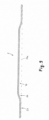
- figure 9 shows a cross-sectional view of a heat-conducting plate 2 according to the invention, which can be circular, oval or polygonal, with a first annular region 50, the underside of which runs in a support plane 10a.
- the first annular area 50 encloses a second, ring-like, cone-shaped or truncated pyramid-shaped area 60, which rises towards a center with a first slope, and a third area 70, which runs parallel to the bearing plane 10a.
- the heat conducting plate can be used to act as an interface between a planar surface heating device and a cooking vessel to ensure optimal heat transfer.
- the heat-conducting plate is designed in such a way that it deforms in the heated state and rests on the heating device essentially over its entire surface.
- the base of a cooking vessel described above is preferably formed by a heat-conducting plate 2, as shown in figure 9 is shown as an example.
Landscapes
- Engineering & Computer Science (AREA)
- Food Science & Technology (AREA)
- Manufacturing & Machinery (AREA)
- Cookers (AREA)
Claims (13)
- Plaque de conduction de chaleur (2) composée d'une pluralité de couches métalliques, et deux couches en acier sont positionnées de part et d'autre d'une couche qui contient de l'aluminium, comportant une première zone annulaire (50, 52, 54, 56, 58, 150, 152, 154) qui forme une surface plate, a un dessous équipé d'un plan de soutien et est conçu pour reposer contre un dispositif chauffant (K) pendant le fonctionnementune deuxième zone annulaire, conique ou tronquée en forme de pyramide (60, 62, 64, 66, 68, 160, 162, 164) qui est délimitée par la première zone annulaire (50, 52, 54, 56, 58, 150, 152, 154) et s'élève suivant une première pente vers le centre etune troisième zone (70, 72, 74, 76, 78, 170, 172, 174) qui est délimitée par la deuxième zone conique ou tronquée en forme de pyramide (60, 62, 64, 66, 68, 160, 162, 164) et dont la pente vers le centre d'une cuve est inférieure en tout point à la première pentese caractérisant par le fait que les première, deuxième et troisième zones ont une épaisseur constante et que la distance entre la troisième zone et la transition avec la deuxième zone annulaire du plan de soutien, à la température ambiante, se situe entre 0,2 et 0,8 mm.
- La plaque de conduction de chaleur que décrit la revendication 1, et qui se caractérise par le fait que la troisième zone (70, 72, 76, 78, 170, 172, 174), qui fait suite à la deuxième zone conique ou tronquée en forme de pyramide (60, 62, 64, 66, 68, 160, 162, 164), en direction du centre, est parallèle au plan de soutien.
- La plaque de conduction de chaleur que décrit la revendication 1, et qui se caractérise par le fait que la troisième zone (74), qui fait suite à la deuxième zone conique ou tronquée en forme de pyramide (64), en direction du centre, s'élève.
- La plaque de conduction de chaleur que décrit la revendication 1, et qui se caractérise par le fait que la troisième zone, qui fait suite à la deuxième zone conique ou tronquée en forme de pyramide, en direction du centre, suit une pente descendante.
- La plaque de conduction de chaleur que décrit l'une ou l'autre des revendications 2 à 4, et qui se caractérise par le fait que la troisième zone (70, 76, 78, 170, 172, 174) a une zone la plus intérieure (80) qui se situe à l'horizontale.
- La plaque de conduction de chaleur que décrit l'une ou l'autre des revendications 2 à 4, et qui se caractérise par le fait que la troisième zone (74) comporte une zone la plus intérieure (84) qui suit un arc montant.
- La plaque de conduction de chaleur que décrit l'une ou l'autre des revendications 2 à 4, et qui se caractérise par le fait que la troisième zone (72) comporte une zone la plus intérieure (82) qui suit un arc descendant.
- La plaque de conduction de chaleur que décrit l'une ou l'autre des revendications précédentes, et qui se caractérise par le fait que les couches en acier ont une épaisseur maximale de 0,7, 0,6, 0,5 ou 0,4 mm et que la couche qui contient de l'aluminium a une épaisseur maximale de 2,5, 2,0, 1,5 ou 1,4 mm.
- La plaque de conduction de chaleur que décrit l'une ou l'autre des revendications précédentes, et qui se caractérise par la présence de plusieurs couches métalliques, et l'une de ces couches métalliques contient un matériau ferromagnétique dont la température de Curie se situe entre 200 et 300°C.
- La plaque de conduction de chaleur que décrit l'une ou l'autre des revendications précédentes, et qui se caractérise par le fait que le dessous de cette plaque de conduction de chaleur a un revêtement contenant du Si.
- La plaque de conduction de chaleur que décrit l'une ou l'autre des revendications 5, 6 ou 7, et qui se caractérise par le fait que lorsqu'un récipient de cuisson atteint une température de plus de 100, 120, 150, 200 ou 250°C, aucun point se situant sous la première zone en forme d'anneau se trouve à une distance de plus de 1, 0,5, 0,3, 0,2 ou 0,1 mm du plan d'appui.
- La plaque de conduction de chaleur que décrit l'une ou l'autre des revendications précédentes, et qui se caractérise par le fait que cette plaque de conduction de chaleur offre un effet gaufré.
- Le récipient de cuisson (10, 12, 14, 16, 18, 110, 112, 114) comporte un socle (20, 22, 24, 26, 28, 120, 122, 124) et une bordure périphérique (30, 32, 34, 36, 38, 130, 132, 134) pointant vers le haut, et ce socle (20, 22, 24, 26, 28, 120, 122, 124) est constitué d'une plaque de conduction de chaleur (2) identique à celle que décrit l'une ou l'autre des revendications précédentes.
Applications Claiming Priority (1)
| Application Number | Priority Date | Filing Date | Title |
|---|---|---|---|
| DE102015015545.8A DE102015015545A1 (de) | 2015-12-03 | 2015-12-03 | Wärmeleitplatte und damit gebildetes Kochgefäß |
Publications (3)
| Publication Number | Publication Date |
|---|---|
| EP3175751A1 EP3175751A1 (fr) | 2017-06-07 |
| EP3175751B1 true EP3175751B1 (fr) | 2023-08-30 |
| EP3175751C0 EP3175751C0 (fr) | 2023-08-30 |
Family
ID=57629224
Family Applications (1)
| Application Number | Title | Priority Date | Filing Date |
|---|---|---|---|
| EP16201997.0A Active EP3175751B1 (fr) | 2015-12-03 | 2016-12-02 | Plaque conductrice de chaleur et récipient de cuisson la comprenant |
Country Status (2)
| Country | Link |
|---|---|
| EP (1) | EP3175751B1 (fr) |
| DE (1) | DE102015015545A1 (fr) |
Families Citing this family (1)
| Publication number | Priority date | Publication date | Assignee | Title |
|---|---|---|---|---|
| DE102017005079B4 (de) * | 2017-05-24 | 2019-11-28 | Acs Coating Systems Gmbh | Kochgefäß mit metallischem Einsatz |
Citations (4)
| Publication number | Priority date | Publication date | Assignee | Title |
|---|---|---|---|---|
| WO1987004911A1 (fr) * | 1986-02-18 | 1987-08-27 | Woo Sung Co., Ltd. | Ustensile de cuisine a triple fond, et son procede de fabrication |
| US5532461A (en) * | 1994-04-15 | 1996-07-02 | Fissler Gmbh | Bottom-heated utensil for conductive or induction heating |
| CN101438932A (zh) * | 2007-11-20 | 2009-05-27 | 珠海格力电器股份有限公司 | 一种电饭煲内锅及其制造方法 |
| WO2012153317A1 (fr) * | 2011-05-12 | 2012-11-15 | Tvs S.P.A. | Récipient pour la cuisson d'aliments et son procédé de fabrication |
Family Cites Families (7)
| Publication number | Priority date | Publication date | Assignee | Title |
|---|---|---|---|---|
| CH96637A (de) * | 1921-05-21 | 1922-11-01 | Zysset Ernst | Kochgeschirr mit gespanntem Boden. |
| US2517584A (en) * | 1946-10-26 | 1950-08-08 | Specialties Dev Corp | Method of forming receptacles |
| DE1938236U (de) * | 1966-03-05 | 1966-05-12 | Wilhelm Reppel | Bratpfanne fuer das ausbacken von pfannengerichten. |
| JPS6179422A (ja) * | 1984-09-20 | 1986-04-23 | リ−ガル ウエア−,インコ−ポレ−テツド | 料理用なべ |
| US4880951A (en) * | 1988-06-03 | 1989-11-14 | General Housewares Corporation | Food preparation kit for use in cooking food in microwave oven or in thermal oven |
| US8796598B2 (en) * | 2007-09-07 | 2014-08-05 | Bose Corporation | Induction cookware |
| EP2206801A1 (fr) * | 2008-12-24 | 2010-07-14 | Seb Sa | Ustensiles de cuisson composites comprenant un revêtement de protection vitreux |
-
2015
- 2015-12-03 DE DE102015015545.8A patent/DE102015015545A1/de not_active Withdrawn
-
2016
- 2016-12-02 EP EP16201997.0A patent/EP3175751B1/fr active Active
Patent Citations (4)
| Publication number | Priority date | Publication date | Assignee | Title |
|---|---|---|---|---|
| WO1987004911A1 (fr) * | 1986-02-18 | 1987-08-27 | Woo Sung Co., Ltd. | Ustensile de cuisine a triple fond, et son procede de fabrication |
| US5532461A (en) * | 1994-04-15 | 1996-07-02 | Fissler Gmbh | Bottom-heated utensil for conductive or induction heating |
| CN101438932A (zh) * | 2007-11-20 | 2009-05-27 | 珠海格力电器股份有限公司 | 一种电饭煲内锅及其制造方法 |
| WO2012153317A1 (fr) * | 2011-05-12 | 2012-11-15 | Tvs S.P.A. | Récipient pour la cuisson d'aliments et son procédé de fabrication |
Also Published As
| Publication number | Publication date |
|---|---|
| EP3175751C0 (fr) | 2023-08-30 |
| DE102015015545A1 (de) | 2017-06-08 |
| EP3175751A1 (fr) | 2017-06-07 |
Similar Documents
| Publication | Publication Date | Title |
|---|---|---|
| DE69520563T4 (de) | Gefässe zum erhitzen von flüssigkeiten | |
| DE3215174C2 (fr) | ||
| DE69919111T2 (de) | Induktionsgeheiztes Kochgefäss und Legierung zur Herstellung eines solchen Gefässes | |
| EP0047490B1 (fr) | Réchaud électrique | |
| DE2205132A1 (de) | Elektrokochgeraet | |
| EP2427086B1 (fr) | Ustensile à induction pour le maintien au chaud d'aliments | |
| EP3175751B1 (fr) | Plaque conductrice de chaleur et récipient de cuisson la comprenant | |
| DE102015002201A1 (de) | Erwärmungsanordnung und Verfahren zu ihrer Herstellung | |
| DE3639037A1 (de) | Kochgeschirr | |
| DE102008011418B3 (de) | Verfahren zum Ausbilden einer Nietverbindung und Nietverbindung | |
| DE102017104727A1 (de) | Kochgeschirr zur Verwendung mit einem Induktionskochfeld | |
| WO2018083565A1 (fr) | Fond de casserole | |
| DE2225530C3 (de) | Selbstreinigender Brennerdeckel für gasbeheizte Haushaltsgeräte | |
| DE7914082U1 (de) | Elektrokochplatte | |
| DE4000536C2 (fr) | ||
| DE9400835U1 (de) | Adapterelement | |
| DE102017005079B4 (de) | Kochgefäß mit metallischem Einsatz | |
| DE102019127028B4 (de) | Gargerätetiegel und Verfahren zu seiner Herstellung | |
| EP4218503B1 (fr) | Cuiseur à vapeur basse pression | |
| DE2329435B2 (de) | Induktionskochgerät | |
| EP3468429B1 (fr) | Ustensile de cuisson à structure sandwich améliorée et à mouvement réduit du fond, procédé de fabrication et utilisation associés | |
| CH580412A5 (en) | Metal cooking pot or container - has recesses on outside base to counteract heat deformation | |
| WO2008110447A2 (fr) | Table de cuisson dotée d'une zone de détection de température | |
| DE102023106136A1 (de) | Verbund-Kochgeschirr aus Hochleistungskeramik und Edelstahl | |
| DE3423472A1 (de) | Kochgeschirr |
Legal Events
| Date | Code | Title | Description |
|---|---|---|---|
| AK | Designated contracting states |
Kind code of ref document: A1 Designated state(s): AL AT BE BG CH CY CZ DE DK EE ES FI FR GB GR HR HU IE IS IT LI LT LU LV MC MK MT NL NO PL PT RO RS SE SI SK SM TR |
|
| AX | Request for extension of the european patent |
Extension state: BA ME |
|
| PUAI | Public reference made under article 153(3) epc to a published international application that has entered the european phase |
Free format text: ORIGINAL CODE: 0009012 |
|
| STAA | Information on the status of an ep patent application or granted ep patent |
Free format text: STATUS: THE APPLICATION HAS BEEN PUBLISHED |
|
| STAA | Information on the status of an ep patent application or granted ep patent |
Free format text: STATUS: REQUEST FOR EXAMINATION WAS MADE |
|
| 17P | Request for examination filed |
Effective date: 20170622 |
|
| RBV | Designated contracting states (corrected) |
Designated state(s): AL AT BE BG CH CY CZ DE DK EE ES FI FR GB GR HR HU IE IS IT LI LT LU LV MC MK MT NL NO PL PT RO RS SE SI SK SM TR |
|
| STAA | Information on the status of an ep patent application or granted ep patent |
Free format text: STATUS: EXAMINATION IS IN PROGRESS |
|
| 17Q | First examination report despatched |
Effective date: 20190311 |
|
| GRAP | Despatch of communication of intention to grant a patent |
Free format text: ORIGINAL CODE: EPIDOSNIGR1 |
|
| STAA | Information on the status of an ep patent application or granted ep patent |
Free format text: STATUS: GRANT OF PATENT IS INTENDED |
|
| INTG | Intention to grant announced |
Effective date: 20230324 |
|
| GRAS | Grant fee paid |
Free format text: ORIGINAL CODE: EPIDOSNIGR3 |
|
| GRAA | (expected) grant |
Free format text: ORIGINAL CODE: 0009210 |
|
| STAA | Information on the status of an ep patent application or granted ep patent |
Free format text: STATUS: THE PATENT HAS BEEN GRANTED |
|
| AK | Designated contracting states |
Kind code of ref document: B1 Designated state(s): AL AT BE BG CH CY CZ DE DK EE ES FI FR GB GR HR HU IE IS IT LI LT LU LV MC MK MT NL NO PL PT RO RS SE SI SK SM TR |
|
| REG | Reference to a national code |
Ref country code: GB Ref legal event code: FG4D Free format text: NOT ENGLISH |
|
| REG | Reference to a national code |
Ref country code: CH Ref legal event code: EP |
|
| REG | Reference to a national code |
Ref country code: DE Ref legal event code: R096 Ref document number: 502016016051 Country of ref document: DE |
|
| REG | Reference to a national code |
Ref country code: IE Ref legal event code: FG4D Free format text: LANGUAGE OF EP DOCUMENT: GERMAN |
|
| U01 | Request for unitary effect filed |
Effective date: 20231002 |
|
| U07 | Unitary effect registered |
Designated state(s): AT BE BG DE DK EE FI FR IT LT LU LV MT NL PT SE SI Effective date: 20231011 |
|
| U20 | Renewal fee for the european patent with unitary effect paid |
Year of fee payment: 8 Effective date: 20231026 |
|
| PG25 | Lapsed in a contracting state [announced via postgrant information from national office to epo] |
Ref country code: GR Free format text: LAPSE BECAUSE OF FAILURE TO SUBMIT A TRANSLATION OF THE DESCRIPTION OR TO PAY THE FEE WITHIN THE PRESCRIBED TIME-LIMIT Effective date: 20231201 |
|
| PG25 | Lapsed in a contracting state [announced via postgrant information from national office to epo] |
Ref country code: IS Free format text: LAPSE BECAUSE OF FAILURE TO SUBMIT A TRANSLATION OF THE DESCRIPTION OR TO PAY THE FEE WITHIN THE PRESCRIBED TIME-LIMIT Effective date: 20231230 |
|
| PG25 | Lapsed in a contracting state [announced via postgrant information from national office to epo] |
Ref country code: RS Free format text: LAPSE BECAUSE OF FAILURE TO SUBMIT A TRANSLATION OF THE DESCRIPTION OR TO PAY THE FEE WITHIN THE PRESCRIBED TIME-LIMIT Effective date: 20230830 Ref country code: NO Free format text: LAPSE BECAUSE OF FAILURE TO SUBMIT A TRANSLATION OF THE DESCRIPTION OR TO PAY THE FEE WITHIN THE PRESCRIBED TIME-LIMIT Effective date: 20231130 Ref country code: IS Free format text: LAPSE BECAUSE OF FAILURE TO SUBMIT A TRANSLATION OF THE DESCRIPTION OR TO PAY THE FEE WITHIN THE PRESCRIBED TIME-LIMIT Effective date: 20231230 Ref country code: HR Free format text: LAPSE BECAUSE OF FAILURE TO SUBMIT A TRANSLATION OF THE DESCRIPTION OR TO PAY THE FEE WITHIN THE PRESCRIBED TIME-LIMIT Effective date: 20230830 Ref country code: GR Free format text: LAPSE BECAUSE OF FAILURE TO SUBMIT A TRANSLATION OF THE DESCRIPTION OR TO PAY THE FEE WITHIN THE PRESCRIBED TIME-LIMIT Effective date: 20231201 |
|
| PG25 | Lapsed in a contracting state [announced via postgrant information from national office to epo] |
Ref country code: PL Free format text: LAPSE BECAUSE OF FAILURE TO SUBMIT A TRANSLATION OF THE DESCRIPTION OR TO PAY THE FEE WITHIN THE PRESCRIBED TIME-LIMIT Effective date: 20230830 |
|
| PG25 | Lapsed in a contracting state [announced via postgrant information from national office to epo] |
Ref country code: ES Free format text: LAPSE BECAUSE OF FAILURE TO SUBMIT A TRANSLATION OF THE DESCRIPTION OR TO PAY THE FEE WITHIN THE PRESCRIBED TIME-LIMIT Effective date: 20230830 |
|
| PG25 | Lapsed in a contracting state [announced via postgrant information from national office to epo] |
Ref country code: SM Free format text: LAPSE BECAUSE OF FAILURE TO SUBMIT A TRANSLATION OF THE DESCRIPTION OR TO PAY THE FEE WITHIN THE PRESCRIBED TIME-LIMIT Effective date: 20230830 Ref country code: RO Free format text: LAPSE BECAUSE OF FAILURE TO SUBMIT A TRANSLATION OF THE DESCRIPTION OR TO PAY THE FEE WITHIN THE PRESCRIBED TIME-LIMIT Effective date: 20230830 Ref country code: ES Free format text: LAPSE BECAUSE OF FAILURE TO SUBMIT A TRANSLATION OF THE DESCRIPTION OR TO PAY THE FEE WITHIN THE PRESCRIBED TIME-LIMIT Effective date: 20230830 Ref country code: CZ Free format text: LAPSE BECAUSE OF FAILURE TO SUBMIT A TRANSLATION OF THE DESCRIPTION OR TO PAY THE FEE WITHIN THE PRESCRIBED TIME-LIMIT Effective date: 20230830 Ref country code: SK Free format text: LAPSE BECAUSE OF FAILURE TO SUBMIT A TRANSLATION OF THE DESCRIPTION OR TO PAY THE FEE WITHIN THE PRESCRIBED TIME-LIMIT Effective date: 20230830 |
|
| REG | Reference to a national code |
Ref country code: DE Ref legal event code: R097 Ref document number: 502016016051 Country of ref document: DE |
|
| PLBE | No opposition filed within time limit |
Free format text: ORIGINAL CODE: 0009261 |
|
| STAA | Information on the status of an ep patent application or granted ep patent |
Free format text: STATUS: NO OPPOSITION FILED WITHIN TIME LIMIT |
|
| REG | Reference to a national code |
Ref country code: CH Ref legal event code: PL |
|
| 26N | No opposition filed |
Effective date: 20240603 |
|
| PG25 | Lapsed in a contracting state [announced via postgrant information from national office to epo] |
Ref country code: MC Free format text: LAPSE BECAUSE OF FAILURE TO SUBMIT A TRANSLATION OF THE DESCRIPTION OR TO PAY THE FEE WITHIN THE PRESCRIBED TIME-LIMIT Effective date: 20230830 |
|
| GBPC | Gb: european patent ceased through non-payment of renewal fee |
Effective date: 20231202 |
|
| PG25 | Lapsed in a contracting state [announced via postgrant information from national office to epo] |
Ref country code: MC Free format text: LAPSE BECAUSE OF FAILURE TO SUBMIT A TRANSLATION OF THE DESCRIPTION OR TO PAY THE FEE WITHIN THE PRESCRIBED TIME-LIMIT Effective date: 20230830 |
|
| REG | Reference to a national code |
Ref country code: IE Ref legal event code: MM4A |
|
| PG25 | Lapsed in a contracting state [announced via postgrant information from national office to epo] |
Ref country code: IE Free format text: LAPSE BECAUSE OF NON-PAYMENT OF DUE FEES Effective date: 20231202 |
|
| PG25 | Lapsed in a contracting state [announced via postgrant information from national office to epo] |
Ref country code: GB Free format text: LAPSE BECAUSE OF NON-PAYMENT OF DUE FEES Effective date: 20231202 |
|
| PG25 | Lapsed in a contracting state [announced via postgrant information from national office to epo] |
Ref country code: CH Free format text: LAPSE BECAUSE OF NON-PAYMENT OF DUE FEES Effective date: 20231231 |
|
| PG25 | Lapsed in a contracting state [announced via postgrant information from national office to epo] |
Ref country code: IE Free format text: LAPSE BECAUSE OF NON-PAYMENT OF DUE FEES Effective date: 20231202 Ref country code: GB Free format text: LAPSE BECAUSE OF NON-PAYMENT OF DUE FEES Effective date: 20231202 Ref country code: CH Free format text: LAPSE BECAUSE OF NON-PAYMENT OF DUE FEES Effective date: 20231231 |
|
| U20 | Renewal fee for the european patent with unitary effect paid |
Year of fee payment: 9 Effective date: 20241225 |
|
| PG25 | Lapsed in a contracting state [announced via postgrant information from national office to epo] |
Ref country code: CY Free format text: LAPSE BECAUSE OF FAILURE TO SUBMIT A TRANSLATION OF THE DESCRIPTION OR TO PAY THE FEE WITHIN THE PRESCRIBED TIME-LIMIT; INVALID AB INITIO Effective date: 20161202 |
|
| PG25 | Lapsed in a contracting state [announced via postgrant information from national office to epo] |
Ref country code: HU Free format text: LAPSE BECAUSE OF FAILURE TO SUBMIT A TRANSLATION OF THE DESCRIPTION OR TO PAY THE FEE WITHIN THE PRESCRIBED TIME-LIMIT; INVALID AB INITIO Effective date: 20161202 |
|
| PG25 | Lapsed in a contracting state [announced via postgrant information from national office to epo] |
Ref country code: TR Free format text: LAPSE BECAUSE OF FAILURE TO SUBMIT A TRANSLATION OF THE DESCRIPTION OR TO PAY THE FEE WITHIN THE PRESCRIBED TIME-LIMIT Effective date: 20230830 |
|
| U20 | Renewal fee for the european patent with unitary effect paid |
Year of fee payment: 10 Effective date: 20251223 |