EP3175952A2 - Dispositif et procédé de fabrication d'affûtage de couteaux tournant - Google Patents
Dispositif et procédé de fabrication d'affûtage de couteaux tournant Download PDFInfo
- Publication number
- EP3175952A2 EP3175952A2 EP16202450.9A EP16202450A EP3175952A2 EP 3175952 A2 EP3175952 A2 EP 3175952A2 EP 16202450 A EP16202450 A EP 16202450A EP 3175952 A2 EP3175952 A2 EP 3175952A2
- Authority
- EP
- European Patent Office
- Prior art keywords
- grinding
- rotary blade
- cutting edge
- grinding tool
- measuring device
- Prior art date
- Legal status (The legal status is an assumption and is not a legal conclusion. Google has not performed a legal analysis and makes no representation as to the accuracy of the status listed.)
- Granted
Links
Images


Classifications
-
- B—PERFORMING OPERATIONS; TRANSPORTING
- B24—GRINDING; POLISHING
- B24B—MACHINES, DEVICES, OR PROCESSES FOR GRINDING OR POLISHING; DRESSING OR CONDITIONING OF ABRADING SURFACES; FEEDING OF GRINDING, POLISHING, OR LAPPING AGENTS
- B24B3/00—Sharpening cutting edges, e.g. of tools; Accessories therefor, e.g. for holding the tools
- B24B3/36—Sharpening cutting edges, e.g. of tools; Accessories therefor, e.g. for holding the tools of cutting blades
- B24B3/40—Processes or apparatus specially adapted for sharpening curved edges
-
- B—PERFORMING OPERATIONS; TRANSPORTING
- B24—GRINDING; POLISHING
- B24B—MACHINES, DEVICES, OR PROCESSES FOR GRINDING OR POLISHING; DRESSING OR CONDITIONING OF ABRADING SURFACES; FEEDING OF GRINDING, POLISHING, OR LAPPING AGENTS
- B24B3/00—Sharpening cutting edges, e.g. of tools; Accessories therefor, e.g. for holding the tools
- B24B3/36—Sharpening cutting edges, e.g. of tools; Accessories therefor, e.g. for holding the tools of cutting blades
- B24B3/46—Sharpening cutting edges, e.g. of tools; Accessories therefor, e.g. for holding the tools of cutting blades of disc blades
- B24B3/463—Sharpening cutting edges, e.g. of tools; Accessories therefor, e.g. for holding the tools of cutting blades of disc blades of slicing machine disc blades
-
- B—PERFORMING OPERATIONS; TRANSPORTING
- B24—GRINDING; POLISHING
- B24B—MACHINES, DEVICES, OR PROCESSES FOR GRINDING OR POLISHING; DRESSING OR CONDITIONING OF ABRADING SURFACES; FEEDING OF GRINDING, POLISHING, OR LAPPING AGENTS
- B24B49/00—Measuring or gauging equipment for controlling the feed movement of the grinding tool or work; Arrangements of indicating or measuring equipment, e.g. for indicating the start of the grinding operation
- B24B49/12—Measuring or gauging equipment for controlling the feed movement of the grinding tool or work; Arrangements of indicating or measuring equipment, e.g. for indicating the start of the grinding operation involving optical means
-
- B—PERFORMING OPERATIONS; TRANSPORTING
- B26—HAND CUTTING TOOLS; CUTTING; SEVERING
- B26D—CUTTING; DETAILS COMMON TO MACHINES FOR PERFORATING, PUNCHING, CUTTING-OUT, STAMPING-OUT OR SEVERING
- B26D7/00—Details of apparatus for cutting, cutting-out, stamping-out, punching, perforating, or severing by means other than cutting
- B26D7/08—Means for treating work or cutting member to facilitate cutting
- B26D7/12—Means for treating work or cutting member to facilitate cutting by sharpening the cutting member
-
- G—PHYSICS
- G01—MEASURING; TESTING
- G01B—MEASURING LENGTH, THICKNESS OR SIMILAR LINEAR DIMENSIONS; MEASURING ANGLES; MEASURING AREAS; MEASURING IRREGULARITIES OF SURFACES OR CONTOURS
- G01B11/00—Measuring arrangements characterised by the use of optical techniques
- G01B11/24—Measuring arrangements characterised by the use of optical techniques for measuring contours or curvatures
- G01B11/2433—Measuring arrangements characterised by the use of optical techniques for measuring contours or curvatures for measuring outlines by shadow casting
-
- B—PERFORMING OPERATIONS; TRANSPORTING
- B26—HAND CUTTING TOOLS; CUTTING; SEVERING
- B26D—CUTTING; DETAILS COMMON TO MACHINES FOR PERFORATING, PUNCHING, CUTTING-OUT, STAMPING-OUT OR SEVERING
- B26D1/00—Cutting through work characterised by the nature or movement of the cutting member or particular materials not otherwise provided for; Apparatus or machines therefor; Cutting members therefor
- B26D1/01—Cutting through work characterised by the nature or movement of the cutting member or particular materials not otherwise provided for; Apparatus or machines therefor; Cutting members therefor involving a cutting member which does not travel with the work
- B26D1/12—Cutting through work characterised by the nature or movement of the cutting member or particular materials not otherwise provided for; Apparatus or machines therefor; Cutting members therefor involving a cutting member which does not travel with the work having a cutting member moving about an axis
- B26D1/14—Cutting through work characterised by the nature or movement of the cutting member or particular materials not otherwise provided for; Apparatus or machines therefor; Cutting members therefor involving a cutting member which does not travel with the work having a cutting member moving about an axis with a circular cutting member, e.g. disc cutter
-
- B—PERFORMING OPERATIONS; TRANSPORTING
- B26—HAND CUTTING TOOLS; CUTTING; SEVERING
- B26D—CUTTING; DETAILS COMMON TO MACHINES FOR PERFORATING, PUNCHING, CUTTING-OUT, STAMPING-OUT OR SEVERING
- B26D2210/00—Machines or methods used for cutting special materials
- B26D2210/02—Machines or methods used for cutting special materials for cutting food products, e.g. food slicers
Definitions
- the present invention relates to a device for grinding rotary knives, in particular sickle or circular knives, in particular for machines for slicing food products, and a method for grinding rotary knives.
- Rotary knives are used in machines for slicing food products, also known as slicers.
- the rotary knives wear out and become dull, so they have to be ground.
- Known rotary knife sharpeners use a copying plate which is a copy of the type of knife to be ground.
- the cutting edge present on the copying plate is traversed. This "Abfahrschul" is transmitted via a copying device to a grinding tool that moves the cutting edge of the rotary blade according to and grinds the rotary blade.
- the present invention has for its object to provide a way by which a rotary blade can be ground in an improved manner.
- a device for grinding rotary knives, in particular sickle or circular knives, in particular for machines for slicing food products, comprises at least one receptacle for a rotary knife to which the rotary knife can be attached, at least one grinding tool, wherein the grinding tool and the attached in the recording Rotary blades are movable relative to each other so that a running on the circumference of the rotary blade cutting edge can be ground by the grinding tool, a measuring device for determining the course of the cutting edge, and a controller which is adapted to the determined cutting edge for controlling the relative movement between the grinding tool and to use the rotary knife.
- edge profile also means the course of the cutting edge angle, which can vary along the circumference of the knife, while the cutting edge lies, for example, on a circle.
- the measuring device is designed to detect as cutting edge a cutting edge or another, the cutting edge corresponding and / or a derivation of the cutting edge gestattendes permitting feature of the rotary blade.
- the cutting edge can be detected particularly easily, for example by a light barrier, which favors the determination of the cutting edge profile.
- the feature which allows derivation of the cutting profile can be, for example, a plurality of elevations or an edge at the transition from a cutting region to a further inner region of the knife, which is arranged on one side of the knife body following the course of the cutting edge are or is, so that the cutting edge can be derived from the detected course of the surveys or the edge.
- a knife with such surveys is for example from the DE 10 2009 006 912 A1 known.
- the measuring device can work without contact. As a result, the measuring device can be protected against contamination and wear.
- the measuring device has a detection range, with which only a portion of the cutting edge can be detected.
- the position of the section can be determined relatively accurately and the cutting edge profile can be determined with sufficient accuracy from a plurality of detected positions of a plurality of cutting sections lying along the cutting edge profile.
- a selective detection of the cutting edge can also be provided so that the cutting edge profile can be determined from a plurality of points detected in this way, for example by interpolation.
- the measuring device and the rotary blade are movable relative to each other such that the cutting edge is movable through the detection range of the measuring device and thereby continuously or partially detectable.
- the cutting edge profile can be detected easily and quickly in the case of selective or sectional detection of the cutting edge.
- the measuring device is movable. In this way it is possible, by moving the measuring device, to detect a section of the cutting edge that crosses the travel path as soon as it comes into the detection range of the measuring device.
- the measuring device preferably has a light barrier, in particular a fork light barrier. This allows a reliable measuring device can be realized simultaneously cost.
- the measuring device is designed to determine the position at which the light barrier is interrupted or released by a section of the cutting edge, as a measured value for the position of this section.
- the position of a section detected by the light barrier relative to a travel path of the light barrier can be detected. This is advantageous because the travel of the light barrier can be measured particularly easily, for example by means of an encoder which is coupled to a drive for moving the light barrier.
- the measuring device is designed to use the set of all positions thus detected at least as the basis for the cutting edge.
- the positions can be assumed directly as cutting edge or it can be further positions, for example by interpolation can be calculated so that the cutting edge can be determined with high accuracy.
- the rotary blade is movable and the measuring device is adapted to determine the position of the rotary blade.
- the measuring device is adapted to determine the position of the rotary blade. This makes it possible to detect the positions in each case depending on the position of the rotary blade and to determine the edge profile, for example in the form of pairs of values, wherein a pair of values a detected position of a portion of the cutting edge, ie a part of the cutting edge profile, and the associated position of the Rotary blade includes.
- the course of the blade can be determined particularly easily if the rotary blade is rotatable about a rotation axis provided for the cutting operation and the measuring device can be moved linearly such that the position of a section of the blade of the rotary blade can be determined for a plurality of rotational positions of the rotary blade by means of the measuring device.
- a memory may be provided for the at least temporary storage of at least one determined edge profile.
- the memory all required, for example, previously learned or entered cutting edge profiles can be kept that correspond to be sharpened knives.
- the invention relates to a device for grinding rotary knives, especially sickle or circular knives, especially for machines for slicing food products, with at least one receptacle for a rotary knife at which the rotary knife is attachable, at least one grinding tool, wherein the grinding tool and the rotary knife mounted in the receptacle are movable relative to each other such that an edge running on the circumference of the rotary blade can be ground by the grinding tool, and a pivoting device for the grinding tool, wherein the pivoting device is designed such that the grinding tool is pivotable about a pivot axis which passes through a grinding point, at which touch the cutting edge and the grinding tool during the grinding operation.
- the grinding tool may comprise a grinding wheel which contacts the cutting edge at the grinding point and is pivotable about the pivot axis. Due to the pivotability of the grinding wheel to the running through the grinding point pivot axis of the grinding angle can be adjusted in a simple manner and in particular also changed during the grinding process, being designated as the grinding angle, the angle between the grinding wheel and the cutting edge. It is thus possible, for example, to set the grinding angle during the grinding process as a function of a determined or predetermined cutting profile.
- the grinding tool may include a Abziehefficiency which forms at least approximately together with the grinding wheel a V-shaped receptacle for the rotary blade and the blade touches a Abziehddling.
- the Abziehefficiency can be removed, for example, by the grinding process resulting burrs from the cutting edge. It is advantageous if the Abziehefficiency is pivotable together with the grinding wheel and / or independently of the grinding wheel about the pivot axis, so that the peel angle, which encloses the Abziehefficiency with the cutting edge, in particular changed during the grinding process and, for example, depending on the determined cutting edge can be adjusted. It is particularly advantageous if the draw-off point also runs through the pivot axis, since then the draw-off point does not or only slightly “migrates" onto the draw-off disk when it is pivoted.
- the grinding wheel and the Abziehsay along the pivot axis offset from each other, in particular such that the two discs with respect to the pivot axis directly opposite each other.
- the two slices can be arranged directly next to one another along the pivot axis so that they touch each other or are only slightly separated from one another (for example, a distance of less than 5 millimeters), forming the V-shaped receptacle.
- the rotary blade and the grinding tool can be positioned relative to one another in such a way that, in particular during the grinding process, the pivot axis is aligned tangentially to the cutting edge present at the respective grinding point. In this way, a particularly good grinding result is achieved.
- the pivoting device for the grinding tool on at least one pivot bearing whose axis of rotation coincides with the pivot axis of the grinding tool.
- the grinding device can be pivoted in a simple manner by means of the pivot bearing during grinding and the grinding angle between the grinding wheel and the cutting edge can be optimally adapted.
- This is particularly advantageous in rotary knives whose cutting edge has a variable cutting angle.
- the cutting angle is the angle that encloses the cutting surface of the cutting edge with a perpendicular to the axis of rotation of the rotary blade extending cutting plane.
- a knife with variable cutting angle is for example from the WO 2009/027080 A1 known.
- a pivot bearing which comprises an axis of rotation coinciding with the pivot axis, has the advantage that the grinding tool can be pivoted extremely precisely and without interference about the grinding point by means of a rotational movement taking place about the axis of rotation and thus the grinding angle can be adapted in a simple manner during the grinding process.
- the grinding wheel and the Abziehin are each attached to a pivot arm, wherein both pivot arms are mounted on the pivot bearing.
- the two discs can be pivotally attached to the pivot bearing in a structurally simple manner.
- the two disks are rotatable for common pivoting about the common axis of rotation of the rotary bearing.
- the grinding wheel and the Abziehfit can thus be pivoted relative to the grinding and Abzieha, which in turn is advantageous when grinding and removing rotary blades with variable cutting angle.
- Each pivoting arm can also be independent of the respective other pivot arm for pivoting the grinding or Abziehfur independently of the other disc to be rotatable about the common axis of rotation of the pivot bearing.
- the two discs can thus be rotated together or independently of each other about the axis of rotation and therefore pivoted about the coincident with the axis of rotation pivot axis, so that the Abzieh- or the grinding angle is adjustable by turning the pivot arms.
- the grinding wheel and the Abziehin may have a common pivot drive.
- the grinding tool can be made compact, whereby the principle of a coincident with the pivot axis axis of rotation having rotary bearing is utilized in a particularly advantageous manner.
- each pivot arm is variable, so that the distance between the arranged on the respective pivot arm disc is adjustable to the pivot bearing.
- the distance between the grinding point and the pivot bearing can be adjusted and adapted, for example, to different sized blades.
- the grinding tool in particular linear, movable, so that the grinding tool and the rotary blade to be ground during the grinding process can be kept in contact with each other, especially if the rotary blade has a varying radius, as is the case with a sickle blade.
- the grinder may include a display indicating the current grinding angle and / or peel angle or other parameters related to the grinding operation.
- the invention also relates to a method for grinding rotary knives, in particular sickle or circular knives, in particular for machines for slicing food products, with a device according to the invention.
- the profile of the cutting edge of the rotary blade is determined and the rotary blade subsequently ground, wherein a relative movement between the rotary blade and a grinding tool is controlled on the basis of the determined cutting edge profile.
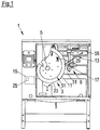
- the illustrated grinding apparatus 1 is provided for grinding rotary blades 3.
- Such rotary blades 3 are used, for example, in high-speed cutting machines for slicing food products, which are also referred to as slicers.
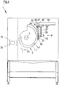
- a receptacle 5 is provided, on which a receiving opening 7 of the rotary knife 3 is placed and on which the rotary knife 3 is fastened (cf. Fig. 1 and 4 ).
- the grinding device 1 has a grinding tool 9.
- the rotary blade 3 and the grinding tool 9 are movable relative to one another so that a cutting edge 11 running on the circumference of the rotary blade 3 can be ground by the grinding tool 9.
- an automatic determination of the profile of the cutting edge 11 by a measuring device 13 which is coupled to a controller 15, so that the determined cutting profile of the controller 15 can be provided.
- the controller 15 is in turn with the grinding tool 9 and a drive (not shown) for the recording. 5 coupled. By the drive, the receptacle 5 and the attached rotary blade 3 can be rotated in a direction of rotation I and the controller 15 is adapted to use the determined cutting edge to control the relative movement between the grinding tool 9 and the rotary blade 3.
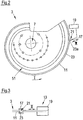
- the measuring device 13 has a forked light barrier 17 which is connected to a linear motor 19 (cf. FIGS. 2 and 3 ) is coupled and arranged so that the fork light barrier 17 is located radially outside the cutting edge 11, see. Fig. 2 .
- a linear motor 19 cf. FIGS. 2 and 3
- the fork light barrier 17 along a travel path II see., The double arrow in Fig. 1 to 3 ) are moved, so that the fork light barrier 17 is moved to the rotary blade 3 to or from this.
- the fork light barrier 17 has a detection area 21 within which an optical path between a transmitter and a receiver (both not shown) of the fork light barrier 17 extends. If the forked light barrier 17 is moved from radially outside to the rotary blade 3 (cf. FIGS. 2 and 3 ), the light path is interrupted by the traverse path II crossing portion 23a of a radially outer cutting edge 23 as soon as the portion 23a enters the detection area 21. With opposite movement of the fork light barrier 17, the light path is released again as soon as the section 23a leaves the detection area again.
- the rotary blade 3 is rotated in the direction of rotation I, so that for a plurality of rotational positions of the rotary blade 3, the respective the path II of the fork light barrier 17 crossing portion 23a of the cutting edge 23 can be detected.
- the determination of the course of the cutting edge 11 then ensues from the quantity of the sections 23a thus detected.
- the respective measured value for the position of a detected section 23a is thereby determined Position of the light barrier 17, based on the travel path II, for example by means of an encoder coupled to the linear motor 19 (not shown), determined by the measuring device 13.
- the measuring device 13 is designed to determine the respective position of the rotary blade 3, with respect to the direction of rotation I, in which the respective section 23a is detected.
- the measuring device 13 is coupled to a position sensor, not shown, which is designed and arranged to detect the position of the rotary blade 3, for example. As a rotation angle relative to a zero point.
- the measuring device 13 therefore determines a multiplicity of value pairs in the described embodiment.
- a pair of values comprises the position of the respective section IIa of the cutting edge 23 crossing the travel path II as well as the associated rotary position of the rotary blade 3.
- the value pairs determined in this way can be assumed directly as the cutting edge profile.
- the measured value indicating the position of a section 23a relative to the travel path II can be converted into a distance value which indicates the distance between the respective section 23a and the center of the receptacle 5 or the receiving opening 7.
- the course of the cutting edge 23 in polar coordinates with the center of the receptacle 5 or the receiving opening 7 can be determined as the origin.
- further value pairs can be calculated by interpolation.
- the measuring device could, for example, be designed such that an edge 51 of the rotary blade 3 running in accordance with the cutting edge 11 (cf. Fig. 1 and 2 ) is detected. It is also conceivable in principle to determine the cutting edge profile by means of a camera and by image evaluation. A relative movement between knife 3 and measuring device 13 is therefore not mandatory for the determination of the cutting edge profile.
- the thus determined edge profile is transmitted by the measuring device 13 to the controller 15 and stored there at least temporarily in a memory 25.
- the forked light barrier 21 is moved away from the rotary blade 3 after the determination of the cutting edge profile.
- the cutting edge 11 is processed in a conventional manner by a grinding and Abziehfit 29, 31 of the grinding tool 9.
- the grinding tool 9 can be positioned relative to the rotary blade 3 in such a way that, in particular during the entire grinding process, the pivot axis 45 is aligned tangentially to the cutting edge 23 extending through the respective grinding point 27.
- the rotary blade 3 is rotated in the direction of rotation I and thus moved past the grinding tool 9.
- the controller 15 is - as mentioned - designed to control the relative movement between the rotary blade 3 and the grinding tool 9 so that the cutting edge 11 is "driven off” according to the determined cutting edge of the grinding tool 9.
- the grinding tool 9 by means of a linear motor 55 along a travel path III (see. Fig. 4 ) are moved to keep the grinding point 27 and the Abzieh Vietnamese 53 in contact with the cutting edge 11, while the rotary blade 3 is moved past the grinding tool 9.
- the grinding tool 9 is thus traced in order to compensate for the changing radius of the rotary blade 3.
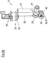
- the grinding tool 9 shown in more detail is fastened to the device 1 via a pivoting device 33.
- the pivoting device 33 has a pivot bearing 35 on which a first and a second pivot arm 37, 39 are rotatably arranged.
- On the first pivot arm 37 is a drive 41 for the grinding wheel 29 and the second pivot arm 39, a drive 43 for the Abziehin 31 is arranged.
- the pivoting device 33 are the grinding and Abziehsay 29, 31 about a through the grinding point 27 and the Abziehddling 53 extending pivot axis 45 pivotally coinciding with the axis of rotation 47 of the pivot bearing 35 (see. Fig.
- the two discs 29, 31 form a V-shaped receptacle for the cutting blade 3.
- the two discs 29, 31 are thus arranged on different sides of the blade 3, ie one disc on the front and the other disc on the Rear side of the knife 3.
- the two discs 29, 31 are, relative to the pivot axis 45, offset from one another.
- the two discs 29, 31 are arranged directly above one another with respect to the pivot axis 45, so that they are directly opposite one another, ie are arranged in close proximity to one another with the formation of the V-shaped receptacle.
- the two discs 29, 31 can thus touch or have only a small distance from each other. Due to the staggered arrangement of the discs 29, 31, the grinding point 27 and the withdrawal point 53 are also along the pivot axis 45 offset from one another.
- the pivot bearing 35 is coupled to a, in particular controllable by the controller 15, pivot drive 49, so that both discs 29, 31 during grinding by the pivot drive 49th pivoted and thus the grinding angle and the peel angle can be adjusted to the cutting angle of the blade 3.
- This type of pivoting is due to the coincident with the pivot axis 45 pivot axis 47 of the pivot bearing 35 extremely precise and also particularly prone to failure. An exact positioning of the Grinding point 27 can thus be ensured even with a change in the grinding angle.
- the discs 29, 31, in particular during grinding can be pivoted independently about the pivot axis 45, so that the grinding angle and the peel angle are independently adjustable. This is achieved in particular in that the two pivot arms 37, 39 are independently rotatable about the axis of rotation 47 of the pivot bearing 35.
- each pivot arm 37, 39 may be variable, so that the distance between the arranged on the respective pivot arm pulley 29, 31 to the pivot bearing 35 is adjustable. The distance between the grinding point 27 and the pivot bearing 35 can thus be changed and adapted to different sized knives.
Landscapes
- Engineering & Computer Science (AREA)
- Mechanical Engineering (AREA)
- Life Sciences & Earth Sciences (AREA)
- Forests & Forestry (AREA)
- Physics & Mathematics (AREA)
- General Physics & Mathematics (AREA)
- Finish Polishing, Edge Sharpening, And Grinding By Specific Grinding Devices (AREA)
- Constituent Portions Of Griding Lathes, Driving, Sensing And Control (AREA)
Applications Claiming Priority (3)
| Application Number | Priority Date | Filing Date | Title |
|---|---|---|---|
| DE102011103418A DE102011103418A1 (de) | 2011-06-06 | 2011-06-06 | Vorrichtung und Verfahren zum Schleifen von Rotationsmessern |
| DE201210005566 DE102012005566A1 (de) | 2012-03-20 | 2012-03-20 | Vorrichtung und Verfahren zum Schleifen von Rotationsmessern |
| EP12170398.7A EP2532477B1 (fr) | 2011-06-06 | 2012-06-01 | Dispositif et procédé de ponçage de lames rotatives |
Related Parent Applications (2)
| Application Number | Title | Priority Date | Filing Date |
|---|---|---|---|
| EP12170398.7A Division EP2532477B1 (fr) | 2011-06-06 | 2012-06-01 | Dispositif et procédé de ponçage de lames rotatives |
| EP12170398.7A Division-Into EP2532477B1 (fr) | 2011-06-06 | 2012-06-01 | Dispositif et procédé de ponçage de lames rotatives |
Publications (3)
| Publication Number | Publication Date |
|---|---|
| EP3175952A2 true EP3175952A2 (fr) | 2017-06-07 |
| EP3175952A3 EP3175952A3 (fr) | 2017-06-28 |
| EP3175952B1 EP3175952B1 (fr) | 2024-07-31 |
Family
ID=46318872
Family Applications (2)
| Application Number | Title | Priority Date | Filing Date |
|---|---|---|---|
| EP16202450.9A Active EP3175952B1 (fr) | 2011-06-06 | 2012-06-01 | Dispositif et procédé de fabrication d'affûtage de couteaux tournant |
| EP12170398.7A Active EP2532477B1 (fr) | 2011-06-06 | 2012-06-01 | Dispositif et procédé de ponçage de lames rotatives |
Family Applications After (1)
| Application Number | Title | Priority Date | Filing Date |
|---|---|---|---|
| EP12170398.7A Active EP2532477B1 (fr) | 2011-06-06 | 2012-06-01 | Dispositif et procédé de ponçage de lames rotatives |
Country Status (4)
| Country | Link |
|---|---|
| US (1) | US9393662B2 (fr) |
| EP (2) | EP3175952B1 (fr) |
| CA (1) | CA2779421C (fr) |
| DE (1) | DE202012012624U1 (fr) |
Cited By (1)
| Publication number | Priority date | Publication date | Assignee | Title |
|---|---|---|---|---|
| DE102021116847A1 (de) | 2021-06-30 | 2023-01-19 | Multivac Sepp Haggenmüller Se & Co. Kg | Aufschneide-Maschine |
Families Citing this family (16)
| Publication number | Priority date | Publication date | Assignee | Title |
|---|---|---|---|---|
| DE102013007275A1 (de) * | 2013-04-26 | 2014-11-13 | Weber Maschinenbau Gmbh Breidenbach | Lebensmittelaufschneidemesser mit einem Funktransponder |
| WO2014183091A1 (fr) * | 2013-05-09 | 2014-11-13 | Lawrence Baker | Système d'affûtage de lame pour une machine de sciage de premier débit |
| DE102013013498A1 (de) * | 2013-08-16 | 2015-02-19 | Dipl.-Ing. Schindler & Wagner Gmbh & Co. Kg | Gerät zum Schärfen von Umlaufmessern |
| DE102013217137A1 (de) * | 2013-08-28 | 2015-03-05 | Weber Maschinenbau Gmbh Breidenbach | Vorrichtung und Verfahren zum Schleifen von Rotationsmessern |
| ITFI20130292A1 (it) * | 2013-11-30 | 2015-05-31 | Futura Spa | Dispositivo per il controllo dell'affilatura di lame a nastro. |
| ITFI20130294A1 (it) * | 2013-12-02 | 2015-06-03 | Futura Spa | Dispositivo di affilatura. |
| CN105479289A (zh) * | 2015-12-29 | 2016-04-13 | 中信戴卡股份有限公司 | 一种在线式通用型车轮刷毛刺装置 |
| ITUA20161489A1 (it) | 2016-03-10 | 2017-09-10 | Gd Spa | Testa di taglio per il taglio di spezzoni a forma di bacchetta in macchine per la produzione di articoli da fumo. |
| EP3366439A1 (fr) * | 2017-02-27 | 2018-08-29 | Bizerba SE & Co. KG | Machine pour la découpe des aliments avec dispositif pour la supervision de la condition du couteau |
| IT201700081306A1 (it) * | 2017-07-18 | 2019-01-18 | Perini Fabio Spa | Gruppo di affilatura per una lama di taglio, macchina comprendente detto gruppo e metodo |
| CN109986639A (zh) * | 2019-05-14 | 2019-07-09 | 南通科诚橡塑机械有限公司 | 一种具有同步手轮机构的橡胶切条装置 |
| CN110370150B (zh) * | 2019-07-30 | 2020-06-23 | 南京宜邦金属制品有限公司 | 一种便于刀片更换的安全型切割机 |
| US12427593B2 (en) * | 2021-05-27 | 2025-09-30 | Ford Gin Services LLC | Gin blade sharpening system and method of use |
| CN113552845B (zh) * | 2021-07-29 | 2022-06-21 | 重庆博张机电设备有限公司 | 一种测量控制方法及结片机 |
| DE102022112000A1 (de) * | 2022-05-12 | 2023-11-16 | Dipl.Ing. S c h i n d l e r & Wagner GmbH & Co KG | Vorrichtung zum Schäfen und Verfahren zum Betrieb der Vorrichtung |
| US20250135593A1 (en) * | 2022-11-10 | 2025-05-01 | Illinois Tool Works Inc. | Food product slicer with optical knife edge evaluation |
Citations (2)
| Publication number | Priority date | Publication date | Assignee | Title |
|---|---|---|---|---|
| WO2009027080A1 (fr) | 2007-08-27 | 2009-03-05 | Weber Maschinenbau Gmbh Breidenbach | Couteau |
| DE102009006912A1 (de) | 2009-01-30 | 2010-08-05 | Weber Maschinenbau Gmbh Breidenbach | Schneidmesser |
Family Cites Families (31)
| Publication number | Priority date | Publication date | Assignee | Title |
|---|---|---|---|---|
| US2207433A (en) * | 1938-03-14 | 1940-07-09 | Harry H Straus | Means for sharpening a circular knife |
| US2429300A (en) * | 1945-10-15 | 1947-10-21 | Martin H Wilbert | Saw-tooth grinder |
| US2766566A (en) * | 1953-08-26 | 1956-10-16 | Gilbertville Woven Label Corp | Sharpening device for cutting wheels |
| US2716908A (en) * | 1954-07-19 | 1955-09-06 | Roland O Lundberg | Automatic grinder for circular saws |
| DE1933993U (de) | 1965-07-07 | 1966-03-03 | Rohde & Doerrenberg | Steuervorrichtung fuer schleifmaschinen fuer mehrschneidige werkzeuge, insbesondere fuer messerkoepfe. |
| US4173846A (en) * | 1978-01-23 | 1979-11-13 | Paper Converting Machine Company | Orbital saw sharpening device |
| CH659790A5 (de) | 1983-06-09 | 1987-02-27 | Paul Kocher Ag | Vorrichtung zum positionieren von bohrern. |
| KR950011673B1 (ko) * | 1991-04-24 | 1995-10-07 | 박경 | 사면폭유지와 판유리 모양감지를 겸할수 있는 롤러장치가 부착된 판유리 변형면취기 |
| JP3317738B2 (ja) | 1993-03-19 | 2002-08-26 | 株式会社太平製作所 | 刃物研削方法および装置 |
| US5152203A (en) * | 1991-08-19 | 1992-10-06 | Paper Converting Machine Company | Apparatus and method for sharpening saw blades having planetary motion in transverse cutting |
| DE4316789A1 (de) | 1993-05-19 | 1994-11-24 | August Heinr Schmidt Gmbh & Co | Verfahren und Vorrichtung zum Schärfen eines Kreissägeblattes |
| DE9321251U1 (de) * | 1993-05-19 | 1996-11-14 | August Heinr. Schmidt GmbH & Co. KG Maschinenfabrik, 70469 Stuttgart | Vorrichtung zum Schärfen eines Kreissägeblattes |
| US5632666A (en) * | 1994-10-28 | 1997-05-27 | Memc Electronic Materials, Inc. | Method and apparatus for automated quality control in wafer slicing |
| US5941148A (en) * | 1998-01-16 | 1999-08-24 | Tidland Corporation | Automatic slitter blade sharpener |
| DE19840801B4 (de) | 1998-09-08 | 2005-09-15 | Walter Maschinenbau Gmbh | Werkzeugmaschine mit automatischer Prozesssteuerung/Überwachung und Verfahren zum Bearbeiten |
| DE19924904A1 (de) * | 1999-05-31 | 2000-12-07 | Fritsch Sondermaschinen Gmbh D | Radiusschleifvorrichtung und Zuführeinrichtung sowie Abrichtvorrichtung hierfür |
| US6224468B1 (en) * | 1999-07-15 | 2001-05-01 | Paper Converting Machine Company | Apparatus and method for sharpening a disc blade |
| JP2001038598A (ja) * | 1999-07-26 | 2001-02-13 | Prima Meat Packers Ltd | 自動研磨機 |
| DE10012445A1 (de) | 2000-03-15 | 2001-09-27 | Hubert Haller | Bearbeitungszentrum |
| JP4590058B2 (ja) * | 2000-04-12 | 2010-12-01 | 株式会社ディスコ | 切削装置の切削ブレード検出機構 |
| DE10021302A1 (de) | 2000-05-02 | 2001-11-08 | Heinz Berger Maschinenfabrik G | Schleifmaschine und Verfahren zum Schärfen von Klingen |
| DE10035743A1 (de) | 2000-07-22 | 2002-04-04 | Deere & Co | Schleifvorrichtung |
| DE10205146A1 (de) | 2002-02-07 | 2003-08-21 | Hauni Maschinenbau Ag | Vorrichtung und Verfahren zum Schleifen von Schneidmessern |
| ES2199052B1 (es) * | 2002-03-26 | 2005-02-01 | Danobat, S. Coop. | Maquina rectificadora de un rotor, con un cabezal rotatorio de dos muelas. |
| FR2847841B1 (fr) | 2002-11-28 | 2005-08-19 | Alain Aveline | Dispositif perfectionne de taillage de meule |
| DE20314680U1 (de) | 2003-09-20 | 2003-11-20 | Oerlikon Geartec AG, Zürich | Schleifmaschine mit Messsystem und Steuerung zum Bereitstellen eines Meistermessers |
| DE102005013363B4 (de) * | 2004-05-13 | 2023-01-05 | Weber Maschinenbau Gmbh Breidenbach | Maschine zum Schärfen von Rotationsmessern |
| DE102004059479B4 (de) | 2004-05-13 | 2006-04-06 | Astor Schneidwerkzeuge Gmbh | Rotationsmesser |
| TR200600864A2 (tr) | 2006-02-24 | 2007-10-22 | Lms Maki̇na Sanayi̇ Ve Ti̇caret Li̇mi̇ted Şi̇rketi̇ | Temizlik kağıdı kesme makinası otomatik bileme tekniği. |
| JP2009231760A (ja) * | 2008-03-25 | 2009-10-08 | Tokyo Seimitsu Co Ltd | ブレード破損/磨耗検出装置 |
| US20120184186A1 (en) * | 2011-01-14 | 2012-07-19 | Graham Jr Dave | Blade sharpening system and method |
-
2012
- 2012-06-01 EP EP16202450.9A patent/EP3175952B1/fr active Active
- 2012-06-01 EP EP12170398.7A patent/EP2532477B1/fr active Active
- 2012-06-01 US US13/486,683 patent/US9393662B2/en active Active
- 2012-06-01 DE DE202012012624U patent/DE202012012624U1/de not_active Expired - Lifetime
- 2012-06-05 CA CA2779421A patent/CA2779421C/fr active Active
Patent Citations (2)
| Publication number | Priority date | Publication date | Assignee | Title |
|---|---|---|---|---|
| WO2009027080A1 (fr) | 2007-08-27 | 2009-03-05 | Weber Maschinenbau Gmbh Breidenbach | Couteau |
| DE102009006912A1 (de) | 2009-01-30 | 2010-08-05 | Weber Maschinenbau Gmbh Breidenbach | Schneidmesser |
Cited By (2)
| Publication number | Priority date | Publication date | Assignee | Title |
|---|---|---|---|---|
| DE102021116847A1 (de) | 2021-06-30 | 2023-01-19 | Multivac Sepp Haggenmüller Se & Co. Kg | Aufschneide-Maschine |
| US12053899B2 (en) | 2021-06-30 | 2024-08-06 | Multivac Sepp Haggenmueller Se & Co. Kg | Slicing machine |
Also Published As
| Publication number | Publication date |
|---|---|
| EP2532477A3 (fr) | 2015-09-09 |
| EP2532477B1 (fr) | 2019-04-24 |
| EP3175952A3 (fr) | 2017-06-28 |
| DE202012012624U1 (de) | 2013-06-28 |
| US20120309266A1 (en) | 2012-12-06 |
| US9393662B2 (en) | 2016-07-19 |
| CA2779421C (fr) | 2019-12-03 |
| EP3175952B1 (fr) | 2024-07-31 |
| EP2532477A2 (fr) | 2012-12-12 |
| CA2779421A1 (fr) | 2012-12-06 |
Similar Documents
| Publication | Publication Date | Title |
|---|---|---|
| EP2532477B1 (fr) | Dispositif et procédé de ponçage de lames rotatives | |
| EP2580033B1 (fr) | Procede et dispositif pour le reglage du jeu de coupe | |
| EP3001823B1 (fr) | Dispositif et procédé d'affûtage de lames rotatives | |
| EP1409210B1 (fr) | Procede pour le reglage de l'epaisseur de coupe | |
| EP2384853A1 (fr) | Meuleuse à double face | |
| DE69701244T2 (de) | Maschine zum Schleifen optischer Gläser | |
| DE202013103409U1 (de) | Vorrichtung zum Bearbeiten einer Oberfläche | |
| DE102011103418A1 (de) | Vorrichtung und Verfahren zum Schleifen von Rotationsmessern | |
| DE2016649C3 (de) | Vorrichtung zum Schleifen von an einem rotierenden, trommelf örmigen Messerträger angeordneten Messern | |
| EP1035938B1 (fr) | Machine pour usiner des pieces munies de dents coupantes, notamment des lames de scie | |
| DE102012005566A1 (de) | Vorrichtung und Verfahren zum Schleifen von Rotationsmessern | |
| EP2030515A2 (fr) | Dispositif et procédé de ponçage de lames de coupe | |
| DE102005013363B4 (de) | Maschine zum Schärfen von Rotationsmessern | |
| DE60122621T2 (de) | Verfahren und Vorrichtung zum Auswuchten von rotierenden Körpern, insbesondere von Läufern für elektrische Motoren | |
| DE102004022360A1 (de) | Verfahren zur Feinbearbeitung, vorzugsweise zur Feinstschlichtbearbeitung, von Werkstücken vorzugsweise von Kurbelwellen | |
| EP1532870A1 (fr) | Dispositif et procédé pour couper tabac d'une bale de tabac | |
| DE102014215232B3 (de) | Schneideinrichtung zum Schneiden von stabförmigen oder strangförmigen Produkten der Tabak verarbeitenden Industrie | |
| EP2603352B1 (fr) | Aiguisoir pourvu d'un support de lame | |
| BE1029177B1 (de) | Verfahren zur Zustandserkennung oder Zustandsbestimmung einer Schneidevorrichtung für landwirtschaftliches Erntegut und landwirtschaftliche Erntemaschine | |
| EP0495354A1 (fr) | Aménagement pour traiter des pièces à usiner de tissu, en particulier en cuir ou similaires | |
| EP0489708B1 (fr) | Dispositif de meulage | |
| EP0993349B1 (fr) | Dispositif pour decouper des aretes longitudinales de bandes plates | |
| EP0510623B1 (fr) | Machine de réaffutage | |
| WO2023051960A1 (fr) | Machine d'usinage de pièces en tôle | |
| DE19924904A1 (de) | Radiusschleifvorrichtung und Zuführeinrichtung sowie Abrichtvorrichtung hierfür |
Legal Events
| Date | Code | Title | Description |
|---|---|---|---|
| PUAL | Search report despatched |
Free format text: ORIGINAL CODE: 0009013 |
|
| AC | Divisional application: reference to earlier application |
Ref document number: 2532477 Country of ref document: EP Kind code of ref document: P |
|
| AK | Designated contracting states |
Kind code of ref document: A2 Designated state(s): AL AT BE BG CH CY CZ DE DK EE ES FI FR GB GR HR HU IE IS IT LI LT LU LV MC MK MT NL NO PL PT RO RS SE SI SK SM TR |
|
| PUAI | Public reference made under article 153(3) epc to a published international application that has entered the european phase |
Free format text: ORIGINAL CODE: 0009012 |
|
| STAA | Information on the status of an ep patent application or granted ep patent |
Free format text: STATUS: THE APPLICATION HAS BEEN PUBLISHED |
|
| AK | Designated contracting states |
Kind code of ref document: A3 Designated state(s): AL AT BE BG CH CY CZ DE DK EE ES FI FR GB GR HR HU IE IS IT LI LT LU LV MC MK MT NL NO PL PT RO RS SE SI SK SM TR |
|
| RIC1 | Information provided on ipc code assigned before grant |
Ipc: B24B 49/12 20060101ALI20170524BHEP Ipc: B24B 3/46 20060101ALI20170524BHEP Ipc: B26D 7/00 20060101ALI20170524BHEP Ipc: B24B 3/40 20060101AFI20170524BHEP |
|
| STAA | Information on the status of an ep patent application or granted ep patent |
Free format text: STATUS: REQUEST FOR EXAMINATION WAS MADE |
|
| 17P | Request for examination filed |
Effective date: 20171228 |
|
| RBV | Designated contracting states (corrected) |
Designated state(s): AL AT BE BG CH CY CZ DE DK EE ES FI FR GB GR HR HU IE IS IT LI LT LU LV MC MK MT NL NO PL PT RO RS SE SI SK SM TR |
|
| STAA | Information on the status of an ep patent application or granted ep patent |
Free format text: STATUS: EXAMINATION IS IN PROGRESS |
|
| 17Q | First examination report despatched |
Effective date: 20210521 |
|
| P01 | Opt-out of the competence of the unified patent court (upc) registered |
Effective date: 20230522 |
|
| RAP3 | Party data changed (applicant data changed or rights of an application transferred) |
Owner name: WEBER FOOD TECHNOLOGY GMBH |
|
| GRAP | Despatch of communication of intention to grant a patent |
Free format text: ORIGINAL CODE: EPIDOSNIGR1 |
|
| STAA | Information on the status of an ep patent application or granted ep patent |
Free format text: STATUS: GRANT OF PATENT IS INTENDED |
|
| INTG | Intention to grant announced |
Effective date: 20240422 |
|
| GRAS | Grant fee paid |
Free format text: ORIGINAL CODE: EPIDOSNIGR3 |
|
| GRAA | (expected) grant |
Free format text: ORIGINAL CODE: 0009210 |
|
| STAA | Information on the status of an ep patent application or granted ep patent |
Free format text: STATUS: THE PATENT HAS BEEN GRANTED |
|
| AC | Divisional application: reference to earlier application |
Ref document number: 2532477 Country of ref document: EP Kind code of ref document: P |
|
| AK | Designated contracting states |
Kind code of ref document: B1 Designated state(s): AL AT BE BG CH CY CZ DE DK EE ES FI FR GB GR HR HU IE IS IT LI LT LU LV MC MK MT NL NO PL PT RO RS SE SI SK SM TR |
|
| REG | Reference to a national code |
Ref country code: CH Ref legal event code: EP Ref country code: GB Ref legal event code: FG4D Free format text: NOT ENGLISH |
|
| REG | Reference to a national code |
Ref country code: DE Ref legal event code: R096 Ref document number: 502012017268 Country of ref document: DE |
|
| REG | Reference to a national code |
Ref country code: IE Ref legal event code: FG4D Free format text: LANGUAGE OF EP DOCUMENT: GERMAN |
|
| REG | Reference to a national code |
Ref country code: LT Ref legal event code: MG9D |
|
| REG | Reference to a national code |
Ref country code: NL Ref legal event code: MP Effective date: 20240731 |
|
| PG25 | Lapsed in a contracting state [announced via postgrant information from national office to epo] |
Ref country code: PT Free format text: LAPSE BECAUSE OF FAILURE TO SUBMIT A TRANSLATION OF THE DESCRIPTION OR TO PAY THE FEE WITHIN THE PRESCRIBED TIME-LIMIT Effective date: 20241202 |
|
| PG25 | Lapsed in a contracting state [announced via postgrant information from national office to epo] |
Ref country code: PT Free format text: LAPSE BECAUSE OF FAILURE TO SUBMIT A TRANSLATION OF THE DESCRIPTION OR TO PAY THE FEE WITHIN THE PRESCRIBED TIME-LIMIT Effective date: 20241202 |
|
| PG25 | Lapsed in a contracting state [announced via postgrant information from national office to epo] |
Ref country code: NO Free format text: LAPSE BECAUSE OF FAILURE TO SUBMIT A TRANSLATION OF THE DESCRIPTION OR TO PAY THE FEE WITHIN THE PRESCRIBED TIME-LIMIT Effective date: 20241031 |
|
| PG25 | Lapsed in a contracting state [announced via postgrant information from national office to epo] |
Ref country code: PL Free format text: LAPSE BECAUSE OF FAILURE TO SUBMIT A TRANSLATION OF THE DESCRIPTION OR TO PAY THE FEE WITHIN THE PRESCRIBED TIME-LIMIT Effective date: 20240731 Ref country code: FI Free format text: LAPSE BECAUSE OF FAILURE TO SUBMIT A TRANSLATION OF THE DESCRIPTION OR TO PAY THE FEE WITHIN THE PRESCRIBED TIME-LIMIT Effective date: 20240731 Ref country code: NL Free format text: LAPSE BECAUSE OF FAILURE TO SUBMIT A TRANSLATION OF THE DESCRIPTION OR TO PAY THE FEE WITHIN THE PRESCRIBED TIME-LIMIT Effective date: 20240731 |
|
| PG25 | Lapsed in a contracting state [announced via postgrant information from national office to epo] |
Ref country code: BG Free format text: LAPSE BECAUSE OF FAILURE TO SUBMIT A TRANSLATION OF THE DESCRIPTION OR TO PAY THE FEE WITHIN THE PRESCRIBED TIME-LIMIT Effective date: 20240731 |
|
| PG25 | Lapsed in a contracting state [announced via postgrant information from national office to epo] |
Ref country code: LV Free format text: LAPSE BECAUSE OF FAILURE TO SUBMIT A TRANSLATION OF THE DESCRIPTION OR TO PAY THE FEE WITHIN THE PRESCRIBED TIME-LIMIT Effective date: 20240731 |
|
| PG25 | Lapsed in a contracting state [announced via postgrant information from national office to epo] |
Ref country code: IS Free format text: LAPSE BECAUSE OF FAILURE TO SUBMIT A TRANSLATION OF THE DESCRIPTION OR TO PAY THE FEE WITHIN THE PRESCRIBED TIME-LIMIT Effective date: 20241130 |
|
| PG25 | Lapsed in a contracting state [announced via postgrant information from national office to epo] |
Ref country code: HR Free format text: LAPSE BECAUSE OF FAILURE TO SUBMIT A TRANSLATION OF THE DESCRIPTION OR TO PAY THE FEE WITHIN THE PRESCRIBED TIME-LIMIT Effective date: 20240731 |
|
| PG25 | Lapsed in a contracting state [announced via postgrant information from national office to epo] |
Ref country code: ES Free format text: LAPSE BECAUSE OF FAILURE TO SUBMIT A TRANSLATION OF THE DESCRIPTION OR TO PAY THE FEE WITHIN THE PRESCRIBED TIME-LIMIT Effective date: 20240731 Ref country code: RS Free format text: LAPSE BECAUSE OF FAILURE TO SUBMIT A TRANSLATION OF THE DESCRIPTION OR TO PAY THE FEE WITHIN THE PRESCRIBED TIME-LIMIT Effective date: 20241031 |
|
| PG25 | Lapsed in a contracting state [announced via postgrant information from national office to epo] |
Ref country code: RS Free format text: LAPSE BECAUSE OF FAILURE TO SUBMIT A TRANSLATION OF THE DESCRIPTION OR TO PAY THE FEE WITHIN THE PRESCRIBED TIME-LIMIT Effective date: 20241031 Ref country code: PL Free format text: LAPSE BECAUSE OF FAILURE TO SUBMIT A TRANSLATION OF THE DESCRIPTION OR TO PAY THE FEE WITHIN THE PRESCRIBED TIME-LIMIT Effective date: 20240731 Ref country code: NO Free format text: LAPSE BECAUSE OF FAILURE TO SUBMIT A TRANSLATION OF THE DESCRIPTION OR TO PAY THE FEE WITHIN THE PRESCRIBED TIME-LIMIT Effective date: 20241031 Ref country code: NL Free format text: LAPSE BECAUSE OF FAILURE TO SUBMIT A TRANSLATION OF THE DESCRIPTION OR TO PAY THE FEE WITHIN THE PRESCRIBED TIME-LIMIT Effective date: 20240731 Ref country code: LV Free format text: LAPSE BECAUSE OF FAILURE TO SUBMIT A TRANSLATION OF THE DESCRIPTION OR TO PAY THE FEE WITHIN THE PRESCRIBED TIME-LIMIT Effective date: 20240731 Ref country code: IS Free format text: LAPSE BECAUSE OF FAILURE TO SUBMIT A TRANSLATION OF THE DESCRIPTION OR TO PAY THE FEE WITHIN THE PRESCRIBED TIME-LIMIT Effective date: 20241130 Ref country code: HR Free format text: LAPSE BECAUSE OF FAILURE TO SUBMIT A TRANSLATION OF THE DESCRIPTION OR TO PAY THE FEE WITHIN THE PRESCRIBED TIME-LIMIT Effective date: 20240731 Ref country code: FI Free format text: LAPSE BECAUSE OF FAILURE TO SUBMIT A TRANSLATION OF THE DESCRIPTION OR TO PAY THE FEE WITHIN THE PRESCRIBED TIME-LIMIT Effective date: 20240731 Ref country code: ES Free format text: LAPSE BECAUSE OF FAILURE TO SUBMIT A TRANSLATION OF THE DESCRIPTION OR TO PAY THE FEE WITHIN THE PRESCRIBED TIME-LIMIT Effective date: 20240731 Ref country code: BG Free format text: LAPSE BECAUSE OF FAILURE TO SUBMIT A TRANSLATION OF THE DESCRIPTION OR TO PAY THE FEE WITHIN THE PRESCRIBED TIME-LIMIT Effective date: 20240731 |
|
| REG | Reference to a national code |
Ref country code: DE Ref legal event code: R081 Ref document number: 502012017268 Country of ref document: DE Owner name: WEBER FOOD TECHNOLOGY SE & CO. KG, DE Free format text: FORMER OWNER: WEBER FOOD TECHNOLOGY GMBH, 35236 BREIDENBACH, DE |
|
| RAP2 | Party data changed (patent owner data changed or rights of a patent transferred) |
Owner name: WEBER FOOD TECHNOLOGY SE & CO. KG |
|
| PG25 | Lapsed in a contracting state [announced via postgrant information from national office to epo] |
Ref country code: SM Free format text: LAPSE BECAUSE OF FAILURE TO SUBMIT A TRANSLATION OF THE DESCRIPTION OR TO PAY THE FEE WITHIN THE PRESCRIBED TIME-LIMIT Effective date: 20240731 Ref country code: RO Free format text: LAPSE BECAUSE OF FAILURE TO SUBMIT A TRANSLATION OF THE DESCRIPTION OR TO PAY THE FEE WITHIN THE PRESCRIBED TIME-LIMIT Effective date: 20240731 Ref country code: DK Free format text: LAPSE BECAUSE OF FAILURE TO SUBMIT A TRANSLATION OF THE DESCRIPTION OR TO PAY THE FEE WITHIN THE PRESCRIBED TIME-LIMIT Effective date: 20240731 |
|
| PG25 | Lapsed in a contracting state [announced via postgrant information from national office to epo] |
Ref country code: EE Free format text: LAPSE BECAUSE OF FAILURE TO SUBMIT A TRANSLATION OF THE DESCRIPTION OR TO PAY THE FEE WITHIN THE PRESCRIBED TIME-LIMIT Effective date: 20240731 |
|
| PG25 | Lapsed in a contracting state [announced via postgrant information from national office to epo] |
Ref country code: CZ Free format text: LAPSE BECAUSE OF FAILURE TO SUBMIT A TRANSLATION OF THE DESCRIPTION OR TO PAY THE FEE WITHIN THE PRESCRIBED TIME-LIMIT Effective date: 20240731 |
|
| PG25 | Lapsed in a contracting state [announced via postgrant information from national office to epo] |
Ref country code: IT Free format text: LAPSE BECAUSE OF FAILURE TO SUBMIT A TRANSLATION OF THE DESCRIPTION OR TO PAY THE FEE WITHIN THE PRESCRIBED TIME-LIMIT Effective date: 20240731 Ref country code: SK Free format text: LAPSE BECAUSE OF FAILURE TO SUBMIT A TRANSLATION OF THE DESCRIPTION OR TO PAY THE FEE WITHIN THE PRESCRIBED TIME-LIMIT Effective date: 20240731 |
|
| REG | Reference to a national code |
Ref country code: DE Ref legal event code: R097 Ref document number: 502012017268 Country of ref document: DE |
|
| PLBE | No opposition filed within time limit |
Free format text: ORIGINAL CODE: 0009261 |
|
| STAA | Information on the status of an ep patent application or granted ep patent |
Free format text: STATUS: NO OPPOSITION FILED WITHIN TIME LIMIT |
|
| 26N | No opposition filed |
Effective date: 20250501 |
|
| PGFP | Annual fee paid to national office [announced via postgrant information from national office to epo] |
Ref country code: DE Payment date: 20250618 Year of fee payment: 14 |
|
| PG25 | Lapsed in a contracting state [announced via postgrant information from national office to epo] |
Ref country code: SE Free format text: LAPSE BECAUSE OF FAILURE TO SUBMIT A TRANSLATION OF THE DESCRIPTION OR TO PAY THE FEE WITHIN THE PRESCRIBED TIME-LIMIT Effective date: 20240731 |
|
| REG | Reference to a national code |
Ref country code: CH Ref legal event code: H13 Free format text: ST27 STATUS EVENT CODE: U-0-0-H10-H13 (AS PROVIDED BY THE NATIONAL OFFICE) Effective date: 20260127 |
|
| PG25 | Lapsed in a contracting state [announced via postgrant information from national office to epo] |
Ref country code: MC Free format text: LAPSE BECAUSE OF FAILURE TO SUBMIT A TRANSLATION OF THE DESCRIPTION OR TO PAY THE FEE WITHIN THE PRESCRIBED TIME-LIMIT Effective date: 20240731 |
|
| PG25 | Lapsed in a contracting state [announced via postgrant information from national office to epo] |
Ref country code: LU Free format text: LAPSE BECAUSE OF NON-PAYMENT OF DUE FEES Effective date: 20250601 |
|
| GBPC | Gb: european patent ceased through non-payment of renewal fee |
Effective date: 20250601 |
|
| REG | Reference to a national code |
Ref country code: BE Ref legal event code: MM Effective date: 20250630 |
|
| PG25 | Lapsed in a contracting state [announced via postgrant information from national office to epo] |
Ref country code: GB Free format text: LAPSE BECAUSE OF NON-PAYMENT OF DUE FEES Effective date: 20250601 |
|
| PG25 | Lapsed in a contracting state [announced via postgrant information from national office to epo] |
Ref country code: IE Free format text: LAPSE BECAUSE OF NON-PAYMENT OF DUE FEES Effective date: 20250601 |
|
| PG25 | Lapsed in a contracting state [announced via postgrant information from national office to epo] |
Ref country code: BE Free format text: LAPSE BECAUSE OF NON-PAYMENT OF DUE FEES Effective date: 20250630 |
|
| PG25 | Lapsed in a contracting state [announced via postgrant information from national office to epo] |
Ref country code: FR Free format text: LAPSE BECAUSE OF NON-PAYMENT OF DUE FEES Effective date: 20250630 |
|
| PG25 | Lapsed in a contracting state [announced via postgrant information from national office to epo] |
Ref country code: CH Free format text: LAPSE BECAUSE OF NON-PAYMENT OF DUE FEES Effective date: 20250630 |