EP3176014A1 - Dispositif de sortie d'air, notamment pour l'introduction d'air dans l'habitacle d'un véhicule automobile - Google Patents
Dispositif de sortie d'air, notamment pour l'introduction d'air dans l'habitacle d'un véhicule automobile Download PDFInfo
- Publication number
- EP3176014A1 EP3176014A1 EP15198128.9A EP15198128A EP3176014A1 EP 3176014 A1 EP3176014 A1 EP 3176014A1 EP 15198128 A EP15198128 A EP 15198128A EP 3176014 A1 EP3176014 A1 EP 3176014A1
- Authority
- EP
- European Patent Office
- Prior art keywords
- air
- outlet
- ring
- axis
- outlet device
- Prior art date
- Legal status (The legal status is an assumption and is not a legal conclusion. Google has not performed a legal analysis and makes no representation as to the accuracy of the status listed.)
- Granted
Links
Images


Classifications
-
- B—PERFORMING OPERATIONS; TRANSPORTING
- B60—VEHICLES IN GENERAL
- B60H—ARRANGEMENTS OF HEATING, COOLING, VENTILATING OR OTHER AIR-TREATING DEVICES SPECIALLY ADAPTED FOR PASSENGER OR GOODS SPACES OF VEHICLES
- B60H1/00—Heating, cooling or ventilating devices
- B60H1/34—Nozzles; Air-diffusers
- B60H1/345—Nozzles; Air-diffusers with means for adjusting divergence, convergence or oscillation of air stream
-
- B—PERFORMING OPERATIONS; TRANSPORTING
- B60—VEHICLES IN GENERAL
- B60H—ARRANGEMENTS OF HEATING, COOLING, VENTILATING OR OTHER AIR-TREATING DEVICES SPECIALLY ADAPTED FOR PASSENGER OR GOODS SPACES OF VEHICLES
- B60H1/00—Heating, cooling or ventilating devices
- B60H1/34—Nozzles; Air-diffusers
- B60H1/3414—Nozzles; Air-diffusers with means for adjusting the air stream direction
- B60H1/3435—Nozzles; Air-diffusers with means for adjusting the air stream direction using only a pivoting frame
- B60H1/3442—Nozzles; Air-diffusers with means for adjusting the air stream direction using only a pivoting frame the frame being spherical
-
- B—PERFORMING OPERATIONS; TRANSPORTING
- B60—VEHICLES IN GENERAL
- B60H—ARRANGEMENTS OF HEATING, COOLING, VENTILATING OR OTHER AIR-TREATING DEVICES SPECIALLY ADAPTED FOR PASSENGER OR GOODS SPACES OF VEHICLES
- B60H1/00—Heating, cooling or ventilating devices
- B60H1/34—Nozzles; Air-diffusers
- B60H2001/3464—Details of hinges
Definitions
- the present invention relates to an air outlet device, in particular for the supply of air into a passenger compartment of a motor vehicle.
- motor vehicles are provided with a dashboard on which there are an instrument panel, object compartments, and a plurality of air outlet devices configured to supply and direct air into the passenger compartment.
- document GB487023A which corresponds to the preamble of claim 1, describes an air outlet device having a tapered nozzle that is rotatable, by means of a ball joint, so as to be convergent to or divergent from the passenger compartment and thus generate, respectively, a concentrated or diffused air current.
- a mushroom-shaped element is fitted to the widest end of the nozzle to divert the air to the side. Said mushroom-shaped element is also movable along the axis of the nozzle so as to close it.
- the purpose of the present invention is to provide an air outlet device, in particular for the supply of air into a passenger compartment of a motor vehicle, which overcomes the problems described above in a simple and economical manner, and preferably consists of a relatively small number of parts and allows the air flow to be directed, regardless of whether said air flow is diffused or concentrated.
- an air outlet device in particular for the supply of air to a passenger compartment of a motor vehicle, as claimed in claim 1.
- reference numeral 1 indicates an air outlet device, in particular for the supply of air to a passenger compartment (not shown) of a motor vehicle.
- the outlet device 1 defines an air duct 2, which starts from a rear inlet 3 communicating, in use, with a ventilation and air conditioning system (not shown) in order to receive an air flow along an axis 5.
- the air duct 2 ends in an outlet 7 ( fig. 2 and fig. 3 ) defined by a rotating member 8.
- the outlet device 1 comprises a supporting structure 9, which preferably consists of two half-shells 9a and 9b, fixed one to the other in a manner that is not described in detail.
- the structure 9 comprises two opposite end portions indicated by reference numerals 10 and 11: the portion 10 defines the inlet 3 and an end part 12 of the air duct 2; on the other hand, the portion 11 defines a seat 13 that is part of a coupling device 14 for coupling the member 8 to the structure 9.
- the member 8 comprises a plurality of deflector walls, for instance four deflector walls, indicated by reference numerals 18, 19, 20 and 21.
- the walls, 18, 19, 20 and 21 are ring-shaped and coaxial along an axis 15, corresponding to the direction along which the air flow is delivered through the outlet device 1.
- the walls 18, 19, 20 and 21 extend transversely to the axis 15 and are axially spaced from one another.
- the walls 18, 19, 20 and 21 have a geometrically identical ring shape that is defined, in particular, by a circular ring.
- the internal perimeter edges of the walls 18, 19, 20 and 21 radially delimit a central axial air duct 16, which is preferably open at both of the axial ends of the member 8.
- the diameters of the internal perimeter edges of the walls 18, 19, 20 and 21 progressively decrease along the axis 15, so that the air duct 16 also has a decreasing diameter.
- the diameters of the external perimeter edges of the walls 18, 19, 20 and 21 also progressively decrease along the axis 15, so that the walls 18, 19, 20 and 21 form a substantially cone-shaped or pyramid-shaped structure.
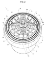
- the walls 18, 19, 20 and 21 have respective front faces 18a, 19a, 20a and 21a ( fig. 1 and fig. 2 ), facing towards the tip of the substantially cone-shaped or pyramid-shaped structure, and respective rear faces 18b, 19b, 20b and 21b ( fig. 3 ) facing the opposite direction.
- each of the front faces 18a 19a, and 21a has an internal perimeter area that directly faces, parallel to the axis 15, an external perimeter area of the rear face 19b, 20b and 21b of the next wall (working towards the tip of the substantially cone-shaped or pyramid-shaped structure), so that each of the walls 19 and 20 partially overlaps the next wall and the previous wall.
- the member 8 further comprises a plurality of spokes 25, for example four, which join the walls 18, 19, 20 and 21 to one another.
- the air ducts 23 thus form respective layers or annuli in the aforesaid cone-shaped or pyramid-shaped structure. Said layers or annuli of air ducts are coaxial and cascaded with respect to one another along the axis 15. As is apparent from the accompanying figures, the layers or annuli of air ducts have respective average diameters of decreasing size.
- the spokes 25 are defined by plates which divide the empty spaces into sectors and thus separate each air duct 23 from the adjacent ones in a circumferential direction.
- said plates are parallel to the axis 15.
- the air ducts 23 have respective radially internal end openings, in correspondence with the air duct 16, and respective radially external end openings, defining an inlet or an outlet for the air with a radial component in the guiding direction.
- the member 8 is rotatable with respect to the structure 9 so as to assume a first and a second configuration, rotated by 180° in relation to one another about an axis 28 that is orthogonal to the axis 15.
- the front faces 18a, 19a, 20a and 21a face towards the passenger compartment, that is to say, towards the outside of the air duct 2.
- the air ducts 23 convey an air flow from the air duct 16 with a radial component towards the outside, so that a diffused air flow is delivered through the outlet 7.
- the air coming from the inlet 3 along the axis 5 comes into contact with the internal perimeter areas of the rear faces 19b, 20b and 21b and is diverted by said internal perimeter areas into the air ducts 23 and, by the latter, with a radial component towards the outside.
- the front faces 18a, 19a, 20a and 21a face towards the inside of the air duct 2.
- the air ducts 23 convey an air flow with a radial component from the outside towards the air duct 16, so that said flow is concentrated in the air duct 17, which thus defines the outlet 7.
- the air coming from the inlet 3 along the axis 5 comes into contact with the external perimeter areas of the front faces 18a, 19a and 20a and is diverted by said external perimeter areas into the air ducts 23 and, by the latter, radially towards the inside of the air duct 16, and then flows along the axis 15 around the tab 26.
- one or more walls 18, 19, 20 and 21 is sloping or tapered with respect to the axis 15, in order to guide the air along directions also having an axial component, in correspondence with the radially internal end openings and/or in correspondence with the radially external end openings of the air ducts 23.
- the introduction of the air into the air ducts 23 and/or the axial channelling from the air ducts 23 to the air duct 16 are facilitated, so that the air flow meets less resistance.
- one or more walls 18, 19, 20 and 21 are shaped so as to comprise two concentric portions joined to one another and having a respectively different slope or taper, so as to optimise the guiding effect and thus reduce the resistance to the air flow to a minimum.
- the walls 18, 19, 20 and 21 may have differently shaped generatrices, which may be more or less effective: for example, according to alternative embodiments that are not shown, the walls 18, 19, 20 and 21 may extend, partially or completely, orthogonal to the axis 15.
- At least one of the walls 18, 19, 20 and 21 has a respective series of through holes (18c, 19c, 20c and 21c) in order to further reduce the resistance to the air flow.
- the holes in each wall 18, 19, 20 and 21 are spaced apart about the axis 15 and angularly staggered with respect to the holes in the immediately preceding and/or immediately following wall along the axis 15, so as not to create preferential channelling in the axial direction that would prevent the air from flowing through the air ducts 23 with the radial direction component.
- the member 8 further comprises at least one tab 26, for example a cross-shaped tab, which projects axially from the rear face 18b of the ring 18 (i.e. the face having the greatest diameter, at the base of the substantially cone-shaped or pyramid-shaped structure).
- the purpose of the tab 26 is to optimise the axial guiding effect at the end of the member 8 and/or to provide an element that the user can grip, for example to manually rotate the member 8 with respect to the structure 9.
- the tab 26 is axially aligned with the spokes 25.
- the device 14 comprises two hinge elements 29, which are part of the member 8 and are arranged along the axis 28 in diametrically opposite positions with respect to the axis 15.
- hinge elements 29 are defined by respective projecting pins, which axially and rotatingly engage respective hinge seats 30 borne by the portion 11 of the structure 9.
- other joint systems for example ball joints
- the device 14 comprises a collar 32, to which the member 8 is hinged about the axis 28.
- the collar 32 is housed in the seat 13 and is coupled to the portion 11 so that its position is adjustable with respect to the structure 9 and the axis 15 can be turned with respect to the axis 5 and, thus, the air flow can be directed towards the outlet 7, regardless of whether said air flow is concentrated or diffused.
- at least part of the seat 13 and at least part of the external surface of the collar 32 have a spherical cap shape so as to define a ball joint, which permits the rotation of the collar 32 and, thus, of the member 8, in any direction.
- the hinge seats 30 are defined by respective recesses, made in a front edge of the collar 32, and closed at the front by a ring 33 which is coaxial with the collar 32 and fixed to the latter in a known way that is not described in detail.
- retaining means for example appropriate friction couplings, are then envisaged to hold the member 32 in a fixed but releasable position about the axis 28 and thus prevent the member 8 from randomly and/or undesirably moving between the first and the second configuration.
- the arrangement and/or the form of the walls 18, 19, 20 and 21, which axially overlap one another in a partial and progressive manner, also helps to guide the air flow better, without penalising one of the two configurations with respect to the other.
- the member 8 is relatively easy to handle and manoeuvre, its overall dimensions are no bigger than those of the air outlet devices known in the prior art and, moreover, it has an aesthetically pleasing design.
- the number of walls that axially delimit the air ducts 23 could be other than four; or the air ducts 23 could be defined by deflector portions differing from the walls 18, 19, 20 and 21 and the spokes 25 in terms of their form and/or position; and/or the air duct 16 could be blind at the tip of the substantially cone-shaped or pyramid-shaped structure.
- the shape of the air ducts 23 could differ from that shown in the accompanying figures; for example, the radially internal end openings of the air ducts 23 could be arranged in an axial direction and parallel to one another at an end of the member 8, without the presence of the air duct 16; and/or the spokes 25 could be smaller and/or shorter, so that the radially internal and/or radially external end openings of the air ducts 23 could be continuous rings and not divided into sectors by the spokes 25.
Landscapes
- Physics & Mathematics (AREA)
- Thermal Sciences (AREA)
- Engineering & Computer Science (AREA)
- Mechanical Engineering (AREA)
- Air-Conditioning For Vehicles (AREA)
Priority Applications (2)
| Application Number | Priority Date | Filing Date | Title |
|---|---|---|---|
| EP15198128.9A EP3176014B1 (fr) | 2015-12-04 | 2015-12-04 | Dispositif de sortie d'air, notamment pour l'introduction d'air dans l'habitacle d'un véhicule automobile |
| US15/367,394 US10286756B2 (en) | 2015-12-04 | 2016-12-02 | Air outlet device, in particular for the supply of air into a passenger compartment of a motor vehicle |
Applications Claiming Priority (1)
| Application Number | Priority Date | Filing Date | Title |
|---|---|---|---|
| EP15198128.9A EP3176014B1 (fr) | 2015-12-04 | 2015-12-04 | Dispositif de sortie d'air, notamment pour l'introduction d'air dans l'habitacle d'un véhicule automobile |
Publications (2)
| Publication Number | Publication Date |
|---|---|
| EP3176014A1 true EP3176014A1 (fr) | 2017-06-07 |
| EP3176014B1 EP3176014B1 (fr) | 2020-05-06 |
Family
ID=55236121
Family Applications (1)
| Application Number | Title | Priority Date | Filing Date |
|---|---|---|---|
| EP15198128.9A Active EP3176014B1 (fr) | 2015-12-04 | 2015-12-04 | Dispositif de sortie d'air, notamment pour l'introduction d'air dans l'habitacle d'un véhicule automobile |
Country Status (2)
| Country | Link |
|---|---|
| US (1) | US10286756B2 (fr) |
| EP (1) | EP3176014B1 (fr) |
Families Citing this family (4)
| Publication number | Priority date | Publication date | Assignee | Title |
|---|---|---|---|---|
| USD836048S1 (en) * | 2016-10-26 | 2018-12-18 | Cary Products Co., Inc. | Three vane louver |
| USD936559S1 (en) * | 2017-12-20 | 2021-11-23 | Classic Auto Air Manufacturing LP | Accessory for vehicle heating and air conditioning systems |
| USD1035522S1 (en) * | 2021-11-02 | 2024-07-16 | Classic Auto Air Manufacturing LP | Vent accessory for vehicle heating and air conditioning systems |
| US20240285465A1 (en) * | 2023-02-28 | 2024-08-29 | Daily Products, Inc. | Methods and apparatus for attachment to a user's exterior surface |
Citations (4)
| Publication number | Priority date | Publication date | Assignee | Title |
|---|---|---|---|---|
| GB487023A (en) | 1937-07-22 | 1938-06-14 | Nl Fabriek Van Bronswerken Voo | Improved air outlet device particularly for apparatus for ventilating ships, railway carriages and aircraft cabins |
| GB768139A (en) * | 1954-03-19 | 1957-02-13 | Anemostat Scotland Ltd | Improvements relating to ventilating devices especially for vehicles |
| EP1690707A1 (fr) * | 2005-02-09 | 2006-08-16 | Key Plastics International | Aérateur pour véhicule comprenant un corps sphérique défini par des déflecteurs |
| DE102014009850A1 (de) * | 2014-07-03 | 2014-12-18 | Daimler Ag | Luftausströmer für ein Fahrzeug, insbesondere einen Personenkraftwagen |
Family Cites Families (3)
| Publication number | Priority date | Publication date | Assignee | Title |
|---|---|---|---|---|
| US3744724A (en) * | 1972-03-24 | 1973-07-10 | Sulzer Ag | Air distributing channel |
| US5791985A (en) * | 1995-06-06 | 1998-08-11 | Tapco International | Modular soffit vent |
| JP6436013B2 (ja) * | 2015-08-04 | 2018-12-12 | 豊田合成株式会社 | 丸型空調用レジスタ |
-
2015
- 2015-12-04 EP EP15198128.9A patent/EP3176014B1/fr active Active
-
2016
- 2016-12-02 US US15/367,394 patent/US10286756B2/en active Active
Patent Citations (4)
| Publication number | Priority date | Publication date | Assignee | Title |
|---|---|---|---|---|
| GB487023A (en) | 1937-07-22 | 1938-06-14 | Nl Fabriek Van Bronswerken Voo | Improved air outlet device particularly for apparatus for ventilating ships, railway carriages and aircraft cabins |
| GB768139A (en) * | 1954-03-19 | 1957-02-13 | Anemostat Scotland Ltd | Improvements relating to ventilating devices especially for vehicles |
| EP1690707A1 (fr) * | 2005-02-09 | 2006-08-16 | Key Plastics International | Aérateur pour véhicule comprenant un corps sphérique défini par des déflecteurs |
| DE102014009850A1 (de) * | 2014-07-03 | 2014-12-18 | Daimler Ag | Luftausströmer für ein Fahrzeug, insbesondere einen Personenkraftwagen |
Also Published As
| Publication number | Publication date |
|---|---|
| EP3176014B1 (fr) | 2020-05-06 |
| US20170158028A1 (en) | 2017-06-08 |
| US10286756B2 (en) | 2019-05-14 |
Similar Documents
| Publication | Publication Date | Title |
|---|---|---|
| CN101622144B (zh) | 带旋流和常规气流的出风口 | |
| US10286756B2 (en) | Air outlet device, in particular for the supply of air into a passenger compartment of a motor vehicle | |
| RU2518092C2 (ru) | Воздуховыпускное устройство | |
| JP2008222228A (ja) | 通風システム用エアベント | |
| US20160031293A1 (en) | Airflow outlet | |
| US20110272049A1 (en) | Coolant-return manifold shut-off valve | |
| US20170036508A1 (en) | Air conditioning round register | |
| JP4473127B2 (ja) | 空気流入器 | |
| JP2015072066A5 (fr) | ||
| CN109203919A (zh) | 用于机动车辆的通风设备的通风通道 | |
| US9895961B2 (en) | Airflow outlet | |
| EP3115614A1 (fr) | Dispositif de ventilation à écoulement d'air radial | |
| US6645065B2 (en) | Air outlet system | |
| JP6344322B2 (ja) | 丸型空調用レジスタ | |
| US9072358B2 (en) | Rotating air directing apparatus for a hair dryer | |
| CN101578187B (zh) | 用于汽车的出风口 | |
| EP3812184A1 (fr) | Groupe de diffuseurs d'air pour véhicule | |
| WO2015140808A1 (fr) | Dispositif d'évacuation d'air comprenant un élément de déflecteur mobile axialement par rapport à un boîtier | |
| CN111098670A (zh) | 出风口 | |
| WO2017085837A1 (fr) | Soufflante | |
| EP3560739A1 (fr) | Buse de climatisation pour un véhicule | |
| DE102006054847A1 (de) | Luftausströmer mit einem Einsatz aus verformbaren Material | |
| CN108698484A (zh) | 空气流出器 | |
| DE102016108009A1 (de) | Luftausströmer | |
| JP2016078667A (ja) | 丸型空調用レジスタ |
Legal Events
| Date | Code | Title | Description |
|---|---|---|---|
| AK | Designated contracting states |
Kind code of ref document: A1 Designated state(s): AL AT BE BG CH CY CZ DE DK EE ES FI FR GB GR HR HU IE IS IT LI LT LU LV MC MK MT NL NO PL PT RO RS SE SI SK SM TR |
|
| AX | Request for extension of the european patent |
Extension state: BA ME |
|
| PUAI | Public reference made under article 153(3) epc to a published international application that has entered the european phase |
Free format text: ORIGINAL CODE: 0009012 |
|
| STAA | Information on the status of an ep patent application or granted ep patent |
Free format text: STATUS: THE APPLICATION HAS BEEN PUBLISHED |
|
| STAA | Information on the status of an ep patent application or granted ep patent |
Free format text: STATUS: REQUEST FOR EXAMINATION WAS MADE |
|
| 17P | Request for examination filed |
Effective date: 20170920 |
|
| RBV | Designated contracting states (corrected) |
Designated state(s): AL AT BE BG CH CY CZ DE DK EE ES FI FR GB GR HR HU IE IS IT LI LT LU LV MC MK MT NL NO PL PT RO RS SE SI SK SM TR |
|
| GRAP | Despatch of communication of intention to grant a patent |
Free format text: ORIGINAL CODE: EPIDOSNIGR1 |
|
| STAA | Information on the status of an ep patent application or granted ep patent |
Free format text: STATUS: GRANT OF PATENT IS INTENDED |
|
| RIC1 | Information provided on ipc code assigned before grant |
Ipc: B60H 1/34 20060101AFI20191114BHEP |
|
| INTG | Intention to grant announced |
Effective date: 20191205 |
|
| GRAS | Grant fee paid |
Free format text: ORIGINAL CODE: EPIDOSNIGR3 |
|
| GRAA | (expected) grant |
Free format text: ORIGINAL CODE: 0009210 |
|
| STAA | Information on the status of an ep patent application or granted ep patent |
Free format text: STATUS: THE PATENT HAS BEEN GRANTED |
|
| AK | Designated contracting states |
Kind code of ref document: B1 Designated state(s): AL AT BE BG CH CY CZ DE DK EE ES FI FR GB GR HR HU IE IS IT LI LT LU LV MC MK MT NL NO PL PT RO RS SE SI SK SM TR |
|
| REG | Reference to a national code |
Ref country code: GB Ref legal event code: FG4D |
|
| REG | Reference to a national code |
Ref country code: AT Ref legal event code: REF Ref document number: 1266190 Country of ref document: AT Kind code of ref document: T Effective date: 20200515 Ref country code: CH Ref legal event code: EP |
|
| REG | Reference to a national code |
Ref country code: IE Ref legal event code: FG4D |
|
| REG | Reference to a national code |
Ref country code: DE Ref legal event code: R096 Ref document number: 602015052079 Country of ref document: DE |
|
| REG | Reference to a national code |
Ref country code: LT Ref legal event code: MG4D |
|
| REG | Reference to a national code |
Ref country code: NL Ref legal event code: MP Effective date: 20200506 |
|
| PG25 | Lapsed in a contracting state [announced via postgrant information from national office to epo] |
Ref country code: LT Free format text: LAPSE BECAUSE OF FAILURE TO SUBMIT A TRANSLATION OF THE DESCRIPTION OR TO PAY THE FEE WITHIN THE PRESCRIBED TIME-LIMIT Effective date: 20200506 Ref country code: SE Free format text: LAPSE BECAUSE OF FAILURE TO SUBMIT A TRANSLATION OF THE DESCRIPTION OR TO PAY THE FEE WITHIN THE PRESCRIBED TIME-LIMIT Effective date: 20200506 Ref country code: GR Free format text: LAPSE BECAUSE OF FAILURE TO SUBMIT A TRANSLATION OF THE DESCRIPTION OR TO PAY THE FEE WITHIN THE PRESCRIBED TIME-LIMIT Effective date: 20200807 Ref country code: NO Free format text: LAPSE BECAUSE OF FAILURE TO SUBMIT A TRANSLATION OF THE DESCRIPTION OR TO PAY THE FEE WITHIN THE PRESCRIBED TIME-LIMIT Effective date: 20200806 Ref country code: FI Free format text: LAPSE BECAUSE OF FAILURE TO SUBMIT A TRANSLATION OF THE DESCRIPTION OR TO PAY THE FEE WITHIN THE PRESCRIBED TIME-LIMIT Effective date: 20200506 Ref country code: IS Free format text: LAPSE BECAUSE OF FAILURE TO SUBMIT A TRANSLATION OF THE DESCRIPTION OR TO PAY THE FEE WITHIN THE PRESCRIBED TIME-LIMIT Effective date: 20200906 Ref country code: PT Free format text: LAPSE BECAUSE OF FAILURE TO SUBMIT A TRANSLATION OF THE DESCRIPTION OR TO PAY THE FEE WITHIN THE PRESCRIBED TIME-LIMIT Effective date: 20200907 |
|
| PG25 | Lapsed in a contracting state [announced via postgrant information from national office to epo] |
Ref country code: RS Free format text: LAPSE BECAUSE OF FAILURE TO SUBMIT A TRANSLATION OF THE DESCRIPTION OR TO PAY THE FEE WITHIN THE PRESCRIBED TIME-LIMIT Effective date: 20200506 Ref country code: LV Free format text: LAPSE BECAUSE OF FAILURE TO SUBMIT A TRANSLATION OF THE DESCRIPTION OR TO PAY THE FEE WITHIN THE PRESCRIBED TIME-LIMIT Effective date: 20200506 Ref country code: HR Free format text: LAPSE BECAUSE OF FAILURE TO SUBMIT A TRANSLATION OF THE DESCRIPTION OR TO PAY THE FEE WITHIN THE PRESCRIBED TIME-LIMIT Effective date: 20200506 Ref country code: BG Free format text: LAPSE BECAUSE OF FAILURE TO SUBMIT A TRANSLATION OF THE DESCRIPTION OR TO PAY THE FEE WITHIN THE PRESCRIBED TIME-LIMIT Effective date: 20200806 |
|
| REG | Reference to a national code |
Ref country code: AT Ref legal event code: MK05 Ref document number: 1266190 Country of ref document: AT Kind code of ref document: T Effective date: 20200506 |
|
| PG25 | Lapsed in a contracting state [announced via postgrant information from national office to epo] |
Ref country code: AL Free format text: LAPSE BECAUSE OF FAILURE TO SUBMIT A TRANSLATION OF THE DESCRIPTION OR TO PAY THE FEE WITHIN THE PRESCRIBED TIME-LIMIT Effective date: 20200506 Ref country code: NL Free format text: LAPSE BECAUSE OF FAILURE TO SUBMIT A TRANSLATION OF THE DESCRIPTION OR TO PAY THE FEE WITHIN THE PRESCRIBED TIME-LIMIT Effective date: 20200506 |
|
| PG25 | Lapsed in a contracting state [announced via postgrant information from national office to epo] |
Ref country code: EE Free format text: LAPSE BECAUSE OF FAILURE TO SUBMIT A TRANSLATION OF THE DESCRIPTION OR TO PAY THE FEE WITHIN THE PRESCRIBED TIME-LIMIT Effective date: 20200506 Ref country code: SM Free format text: LAPSE BECAUSE OF FAILURE TO SUBMIT A TRANSLATION OF THE DESCRIPTION OR TO PAY THE FEE WITHIN THE PRESCRIBED TIME-LIMIT Effective date: 20200506 Ref country code: CZ Free format text: LAPSE BECAUSE OF FAILURE TO SUBMIT A TRANSLATION OF THE DESCRIPTION OR TO PAY THE FEE WITHIN THE PRESCRIBED TIME-LIMIT Effective date: 20200506 Ref country code: RO Free format text: LAPSE BECAUSE OF FAILURE TO SUBMIT A TRANSLATION OF THE DESCRIPTION OR TO PAY THE FEE WITHIN THE PRESCRIBED TIME-LIMIT Effective date: 20200506 Ref country code: DK Free format text: LAPSE BECAUSE OF FAILURE TO SUBMIT A TRANSLATION OF THE DESCRIPTION OR TO PAY THE FEE WITHIN THE PRESCRIBED TIME-LIMIT Effective date: 20200506 Ref country code: ES Free format text: LAPSE BECAUSE OF FAILURE TO SUBMIT A TRANSLATION OF THE DESCRIPTION OR TO PAY THE FEE WITHIN THE PRESCRIBED TIME-LIMIT Effective date: 20200506 Ref country code: AT Free format text: LAPSE BECAUSE OF FAILURE TO SUBMIT A TRANSLATION OF THE DESCRIPTION OR TO PAY THE FEE WITHIN THE PRESCRIBED TIME-LIMIT Effective date: 20200506 |
|
| REG | Reference to a national code |
Ref country code: DE Ref legal event code: R097 Ref document number: 602015052079 Country of ref document: DE |
|
| PG25 | Lapsed in a contracting state [announced via postgrant information from national office to epo] |
Ref country code: SK Free format text: LAPSE BECAUSE OF FAILURE TO SUBMIT A TRANSLATION OF THE DESCRIPTION OR TO PAY THE FEE WITHIN THE PRESCRIBED TIME-LIMIT Effective date: 20200506 Ref country code: PL Free format text: LAPSE BECAUSE OF FAILURE TO SUBMIT A TRANSLATION OF THE DESCRIPTION OR TO PAY THE FEE WITHIN THE PRESCRIBED TIME-LIMIT Effective date: 20200506 |
|
| PLBE | No opposition filed within time limit |
Free format text: ORIGINAL CODE: 0009261 |
|
| STAA | Information on the status of an ep patent application or granted ep patent |
Free format text: STATUS: NO OPPOSITION FILED WITHIN TIME LIMIT |
|
| 26N | No opposition filed |
Effective date: 20210209 |
|
| PG25 | Lapsed in a contracting state [announced via postgrant information from national office to epo] |
Ref country code: SI Free format text: LAPSE BECAUSE OF FAILURE TO SUBMIT A TRANSLATION OF THE DESCRIPTION OR TO PAY THE FEE WITHIN THE PRESCRIBED TIME-LIMIT Effective date: 20200506 |
|
| REG | Reference to a national code |
Ref country code: CH Ref legal event code: PL |
|
| GBPC | Gb: european patent ceased through non-payment of renewal fee |
Effective date: 20201204 |
|
| PG25 | Lapsed in a contracting state [announced via postgrant information from national office to epo] |
Ref country code: MC Free format text: LAPSE BECAUSE OF FAILURE TO SUBMIT A TRANSLATION OF THE DESCRIPTION OR TO PAY THE FEE WITHIN THE PRESCRIBED TIME-LIMIT Effective date: 20200506 |
|
| REG | Reference to a national code |
Ref country code: BE Ref legal event code: MM Effective date: 20201231 |
|
| PG25 | Lapsed in a contracting state [announced via postgrant information from national office to epo] |
Ref country code: LU Free format text: LAPSE BECAUSE OF NON-PAYMENT OF DUE FEES Effective date: 20201204 Ref country code: IE Free format text: LAPSE BECAUSE OF NON-PAYMENT OF DUE FEES Effective date: 20201204 |
|
| PG25 | Lapsed in a contracting state [announced via postgrant information from national office to epo] |
Ref country code: LI Free format text: LAPSE BECAUSE OF NON-PAYMENT OF DUE FEES Effective date: 20201231 Ref country code: GB Free format text: LAPSE BECAUSE OF NON-PAYMENT OF DUE FEES Effective date: 20201204 Ref country code: CH Free format text: LAPSE BECAUSE OF NON-PAYMENT OF DUE FEES Effective date: 20201231 |
|
| PG25 | Lapsed in a contracting state [announced via postgrant information from national office to epo] |
Ref country code: TR Free format text: LAPSE BECAUSE OF FAILURE TO SUBMIT A TRANSLATION OF THE DESCRIPTION OR TO PAY THE FEE WITHIN THE PRESCRIBED TIME-LIMIT Effective date: 20200506 Ref country code: MT Free format text: LAPSE BECAUSE OF FAILURE TO SUBMIT A TRANSLATION OF THE DESCRIPTION OR TO PAY THE FEE WITHIN THE PRESCRIBED TIME-LIMIT Effective date: 20200506 Ref country code: CY Free format text: LAPSE BECAUSE OF FAILURE TO SUBMIT A TRANSLATION OF THE DESCRIPTION OR TO PAY THE FEE WITHIN THE PRESCRIBED TIME-LIMIT Effective date: 20200506 |
|
| PG25 | Lapsed in a contracting state [announced via postgrant information from national office to epo] |
Ref country code: MK Free format text: LAPSE BECAUSE OF FAILURE TO SUBMIT A TRANSLATION OF THE DESCRIPTION OR TO PAY THE FEE WITHIN THE PRESCRIBED TIME-LIMIT Effective date: 20200506 |
|
| PG25 | Lapsed in a contracting state [announced via postgrant information from national office to epo] |
Ref country code: BE Free format text: LAPSE BECAUSE OF NON-PAYMENT OF DUE FEES Effective date: 20201231 |
|
| PGFP | Annual fee paid to national office [announced via postgrant information from national office to epo] |
Ref country code: DE Payment date: 20241121 Year of fee payment: 10 |
|
| PGFP | Annual fee paid to national office [announced via postgrant information from national office to epo] |
Ref country code: FR Payment date: 20241121 Year of fee payment: 10 |
|
| PGFP | Annual fee paid to national office [announced via postgrant information from national office to epo] |
Ref country code: IT Payment date: 20241121 Year of fee payment: 10 |
|
| PG25 | Lapsed in a contracting state [announced via postgrant information from national office to epo] |
Ref country code: IS Free format text: LAPSE BECAUSE OF NON-PAYMENT OF DUE FEES Effective date: 20200906 |