EP3176064B1 - Unité de roue avec un frein à disque et une bague capteur - Google Patents
Unité de roue avec un frein à disque et une bague capteur Download PDFInfo
- Publication number
- EP3176064B1 EP3176064B1 EP16200038.4A EP16200038A EP3176064B1 EP 3176064 B1 EP3176064 B1 EP 3176064B1 EP 16200038 A EP16200038 A EP 16200038A EP 3176064 B1 EP3176064 B1 EP 3176064B1
- Authority
- EP
- European Patent Office
- Prior art keywords
- sensor
- brake disc
- wheel unit
- axis
- sensor ring
- Prior art date
- Legal status (The legal status is an assumption and is not a legal conclusion. Google has not performed a legal analysis and makes no representation as to the accuracy of the status listed.)
- Active
Links
Images











Classifications
-
- B—PERFORMING OPERATIONS; TRANSPORTING
- B60—VEHICLES IN GENERAL
- B60B—VEHICLE WHEELS; CASTORS; AXLES FOR WHEELS OR CASTORS; INCREASING WHEEL ADHESION
- B60B27/00—Hubs
- B60B27/0047—Hubs characterised by functional integration of other elements
- B60B27/0052—Hubs characterised by functional integration of other elements the element being a brake disc
-
- B—PERFORMING OPERATIONS; TRANSPORTING
- B60—VEHICLES IN GENERAL
- B60B—VEHICLE WHEELS; CASTORS; AXLES FOR WHEELS OR CASTORS; INCREASING WHEEL ADHESION
- B60B1/00—Spoked wheels; Spokes thereof
- B60B1/003—Spoked wheels; Spokes thereof specially adapted for bicycles
-
- B—PERFORMING OPERATIONS; TRANSPORTING
- B60—VEHICLES IN GENERAL
- B60B—VEHICLE WHEELS; CASTORS; AXLES FOR WHEELS OR CASTORS; INCREASING WHEEL ADHESION
- B60B27/00—Hubs
- B60B27/0047—Hubs characterised by functional integration of other elements
- B60B27/0068—Hubs characterised by functional integration of other elements the element being a sensor
-
- B—PERFORMING OPERATIONS; TRANSPORTING
- B60—VEHICLES IN GENERAL
- B60B—VEHICLE WHEELS; CASTORS; AXLES FOR WHEELS OR CASTORS; INCREASING WHEEL ADHESION
- B60B27/00—Hubs
- B60B27/02—Hubs adapted to be rotatably arranged on axle
- B60B27/023—Hubs adapted to be rotatably arranged on axle specially adapted for bicycles
-
- B—PERFORMING OPERATIONS; TRANSPORTING
- B60—VEHICLES IN GENERAL
- B60T—VEHICLE BRAKE CONTROL SYSTEMS OR PARTS THEREOF; BRAKE CONTROL SYSTEMS OR PARTS THEREOF, IN GENERAL; ARRANGEMENT OF BRAKING ELEMENTS ON VEHICLES IN GENERAL; PORTABLE DEVICES FOR PREVENTING UNWANTED MOVEMENT OF VEHICLES; VEHICLE MODIFICATIONS TO FACILITATE COOLING OF BRAKES
- B60T8/00—Arrangements for adjusting wheel-braking force to meet varying vehicular or ground-surface conditions, e.g. limiting or varying distribution of braking force
- B60T8/17—Using electrical or electronic regulation means to control braking
- B60T8/1701—Braking or traction control means specially adapted for particular types of vehicles
- B60T8/1706—Braking or traction control means specially adapted for particular types of vehicles for single-track vehicles, e.g. motorcycles
-
- B—PERFORMING OPERATIONS; TRANSPORTING
- B60—VEHICLES IN GENERAL
- B60T—VEHICLE BRAKE CONTROL SYSTEMS OR PARTS THEREOF; BRAKE CONTROL SYSTEMS OR PARTS THEREOF, IN GENERAL; ARRANGEMENT OF BRAKING ELEMENTS ON VEHICLES IN GENERAL; PORTABLE DEVICES FOR PREVENTING UNWANTED MOVEMENT OF VEHICLES; VEHICLE MODIFICATIONS TO FACILITATE COOLING OF BRAKES
- B60T8/00—Arrangements for adjusting wheel-braking force to meet varying vehicular or ground-surface conditions, e.g. limiting or varying distribution of braking force
- B60T8/17—Using electrical or electronic regulation means to control braking
- B60T8/176—Brake regulation specially adapted to prevent excessive wheel slip during vehicle deceleration, e.g. ABS
-
- B—PERFORMING OPERATIONS; TRANSPORTING
- B60—VEHICLES IN GENERAL
- B60T—VEHICLE BRAKE CONTROL SYSTEMS OR PARTS THEREOF; BRAKE CONTROL SYSTEMS OR PARTS THEREOF, IN GENERAL; ARRANGEMENT OF BRAKING ELEMENTS ON VEHICLES IN GENERAL; PORTABLE DEVICES FOR PREVENTING UNWANTED MOVEMENT OF VEHICLES; VEHICLE MODIFICATIONS TO FACILITATE COOLING OF BRAKES
- B60T8/00—Arrangements for adjusting wheel-braking force to meet varying vehicular or ground-surface conditions, e.g. limiting or varying distribution of braking force
- B60T8/32—Arrangements for adjusting wheel-braking force to meet varying vehicular or ground-surface conditions, e.g. limiting or varying distribution of braking force responsive to a speed condition, e.g. acceleration or deceleration
- B60T8/321—Arrangements for adjusting wheel-braking force to meet varying vehicular or ground-surface conditions, e.g. limiting or varying distribution of braking force responsive to a speed condition, e.g. acceleration or deceleration deceleration
- B60T8/329—Systems characterised by their speed sensor arrangements
-
- B—PERFORMING OPERATIONS; TRANSPORTING
- B62—LAND VEHICLES FOR TRAVELLING OTHERWISE THAN ON RAILS
- B62J—CYCLE SADDLES OR SEATS; AUXILIARY DEVICES OR ACCESSORIES SPECIALLY ADAPTED TO CYCLES AND NOT OTHERWISE PROVIDED FOR, e.g. ARTICLE CARRIERS OR CYCLE PROTECTORS
- B62J45/00—Electrical equipment arrangements specially adapted for use as accessories on cycles, not otherwise provided for
- B62J45/40—Sensor arrangements; Mounting thereof
- B62J45/41—Sensor arrangements; Mounting thereof characterised by the type of sensor
- B62J45/413—Rotation sensors
-
- B—PERFORMING OPERATIONS; TRANSPORTING
- B62—LAND VEHICLES FOR TRAVELLING OTHERWISE THAN ON RAILS
- B62L—BRAKES SPECIALLY ADAPTED FOR CYCLES
- B62L1/00—Brakes; Arrangements thereof
- B62L1/005—Brakes; Arrangements thereof constructional features of brake elements, e.g. fastening of brake blocks in their holders
-
- B—PERFORMING OPERATIONS; TRANSPORTING
- B62—LAND VEHICLES FOR TRAVELLING OTHERWISE THAN ON RAILS
- B62L—BRAKES SPECIALLY ADAPTED FOR CYCLES
- B62L3/00—Brake-actuating mechanisms; Arrangements thereof
- B62L3/02—Brake-actuating mechanisms; Arrangements thereof for control by a hand lever
- B62L3/023—Brake-actuating mechanisms; Arrangements thereof for control by a hand lever acting on fluid pressure systems
-
- B—PERFORMING OPERATIONS; TRANSPORTING
- B62—LAND VEHICLES FOR TRAVELLING OTHERWISE THAN ON RAILS
- B62M—RIDER PROPULSION OF WHEELED VEHICLES OR SLEDGES; POWERED PROPULSION OF SLEDGES OR SINGLE-TRACK CYCLES; TRANSMISSIONS SPECIALLY ADAPTED FOR SUCH VEHICLES
- B62M6/00—Rider propulsion of wheeled vehicles with additional source of power, e.g. combustion engine or electric motor
- B62M6/40—Rider propelled cycles with auxiliary electric motor
-
- B—PERFORMING OPERATIONS; TRANSPORTING
- B62—LAND VEHICLES FOR TRAVELLING OTHERWISE THAN ON RAILS
- B62M—RIDER PROPULSION OF WHEELED VEHICLES OR SLEDGES; POWERED PROPULSION OF SLEDGES OR SINGLE-TRACK CYCLES; TRANSMISSIONS SPECIALLY ADAPTED FOR SUCH VEHICLES
- B62M6/00—Rider propulsion of wheeled vehicles with additional source of power, e.g. combustion engine or electric motor
- B62M6/40—Rider propelled cycles with auxiliary electric motor
- B62M6/45—Control or actuating devices therefor
-
- G—PHYSICS
- G01—MEASURING; TESTING
- G01P—MEASURING LINEAR OR ANGULAR SPEED, ACCELERATION, DECELERATION, OR SHOCK; INDICATING PRESENCE, ABSENCE, OR DIRECTION, OF MOVEMENT
- G01P3/00—Measuring linear or angular speed; Measuring differences of linear or angular speeds
- G01P3/42—Devices characterised by the use of electric or magnetic means
- G01P3/44—Devices characterised by the use of electric or magnetic means for measuring angular speed
- G01P3/48—Devices characterised by the use of electric or magnetic means for measuring angular speed by measuring frequency of generated current or voltage
- G01P3/481—Devices characterised by the use of electric or magnetic means for measuring angular speed by measuring frequency of generated current or voltage of pulse signals
- G01P3/488—Devices characterised by the use of electric or magnetic means for measuring angular speed by measuring frequency of generated current or voltage of pulse signals delivered by variable reluctance detectors
-
- B—PERFORMING OPERATIONS; TRANSPORTING
- B60—VEHICLES IN GENERAL
- B60T—VEHICLE BRAKE CONTROL SYSTEMS OR PARTS THEREOF; BRAKE CONTROL SYSTEMS OR PARTS THEREOF, IN GENERAL; ARRANGEMENT OF BRAKING ELEMENTS ON VEHICLES IN GENERAL; PORTABLE DEVICES FOR PREVENTING UNWANTED MOVEMENT OF VEHICLES; VEHICLE MODIFICATIONS TO FACILITATE COOLING OF BRAKES
- B60T8/00—Arrangements for adjusting wheel-braking force to meet varying vehicular or ground-surface conditions, e.g. limiting or varying distribution of braking force
- B60T8/32—Arrangements for adjusting wheel-braking force to meet varying vehicular or ground-surface conditions, e.g. limiting or varying distribution of braking force responsive to a speed condition, e.g. acceleration or deceleration
- B60T8/321—Arrangements for adjusting wheel-braking force to meet varying vehicular or ground-surface conditions, e.g. limiting or varying distribution of braking force responsive to a speed condition, e.g. acceleration or deceleration deceleration
- B60T8/3225—Systems specially adapted for single-track vehicles, e.g. motorcycles
-
- B—PERFORMING OPERATIONS; TRANSPORTING
- B62—LAND VEHICLES FOR TRAVELLING OTHERWISE THAN ON RAILS
- B62K—CYCLES; CYCLE FRAMES; CYCLE STEERING DEVICES; RIDER-OPERATED TERMINAL CONTROLS SPECIALLY ADAPTED FOR CYCLES; CYCLE AXLE SUSPENSIONS; CYCLE SIDECARS, FORECARS, OR THE LIKE
- B62K25/00—Axle suspensions
-
- B—PERFORMING OPERATIONS; TRANSPORTING
- B62—LAND VEHICLES FOR TRAVELLING OTHERWISE THAN ON RAILS
- B62K—CYCLES; CYCLE FRAMES; CYCLE STEERING DEVICES; RIDER-OPERATED TERMINAL CONTROLS SPECIALLY ADAPTED FOR CYCLES; CYCLE AXLE SUSPENSIONS; CYCLE SIDECARS, FORECARS, OR THE LIKE
- B62K3/00—Bicycles
- B62K3/02—Frames
Definitions
- the invention relates to a wheel unit for a bicycle comprising a hub and a rim, which is arranged rotatably movable about an axis of rotation, wherein the hub and the rim are connected to each other by spokes.
- Such wheel units for bicycles are known from the prior art.
- ABS anti-lock braking system
- wheel units are designed for requirements for bicycles, as exemplified below, and these wheel units for bicycles are mountable to the bicycle.
- the bicycle comprises a front wheel unit and a rear wheel unit, wherein the wheel units are interconnected by a frame.
- a bicycle is to be understood as meaning a vehicle which is driven only by the muscular force of a driver or which can be driven by the driver's muscular strength and which comprises an additional drive which operates in particular without exhaust gas, for example without CO 2 emission.
- the additional drive in particular supplements the drive by the human muscle power and / or, for example, in phases, in particular for the driver strenuous driving sections replaced.
- the auxiliary drive comprises, in particular, an electric drive motor, which is preferably supplied with electrical energy from a power store or from a fuel cell.
- the auxiliary drive and thus, in particular, the bicycle for driving requires no fossil fuels.
- bicycle in the sense used here includes in particular bicycles which can only be driven by the muscular force of the driver, and bicycles which can be driven, for example, by the driver's muscular strength, with a permanently acting or shiftable additional drive, for example e-bikes and pedelecs. So electrically powered bicycles.
- such bicycles reach maximum speeds of at most 100 km / h, for example of at most 80 km / h, in particular of at most 60 km / h, in particular of at most 40 km / h.
- the bicycle and thus in particular the wheel unit for the bicycle in lightweight construction designed for such a maximum speed.
- bicycles as used herein are light vehicles having a weight, for example, of at most 100 kg, in particular of at most 80 kg, most suitably of at most 50 kg, in particular of at most 30 kg, so that the wheel unit the bicycle for a load with a such maximum weight plus the weight of the driver is designed.
- the invention has for its object to improve a generic wheel unit for a bicycle.
- the wheel unit can be detected by a sensor ring for a sensor and thus the wheel unit is designed such that rolling characteristics of the wheel unit, for example a rotational speed of a wheel of the wheel unit, can be determined for the sensor.
- the sensor ring Since the sensor ring is arranged adjacent to the brake disc, a small space for the two elements is necessary, so that the sensor ring in addition to the brake disc on the hub can be mounted, although in the generic wheel units for bicycles little free space is available.
- the brake disc can be mounted by the inventive arrangement of the brake disc and the sensor ring according to the usual standardizations, for example with respect to the arrangement of the brake disc in an axial direction to the axis of rotation.
- the senor ring is supported on the brake disc and thereby the two elements are tightly mounted, so that only a very small space is required and on the other a stable arrangement of the elements is possible.
- the senor ring rests directly on the brake disk, and thus no further space between the two elements is needed.
- an intermediate layer is arranged between the sensor ring and the brake disk.
- the intermediate layer reduces the noise of the brake disc and the sensor ring and / or protects the components from corrosion.
- the intermediate layer is at least partially formed as a plastic layer.
- the intermediate layer is essentially an adhesive film.
- the intermediate layer comprises a lacquer layer.
- the intermediate layer comprises a sealing paper.
- the intermediate layer has a thickness with respect to the axial direction to the axis of rotation, which is smaller than 1.5 mm, for example less than 1.2 mm, in particular less than 1 mm, in particular preferably less than 0.8 mm.
- the brake disc is powder-coated, whereby it is protected from external influences and a longer service life is possible.
- the brake disc is painted, for example.
- the thickness of the brake disc, based on an extension in an axial direction to the axis of rotation for example, greater than 1 mm, in particular greater than 1.5 mm, more preferably greater than 1.8 mm is and, for example, it is provided that the thickness of the brake disc, based on the extension in the axial direction to the axis of rotation is less than 4 mm, in particular less than 3.7 mm, in a particularly preferred smaller than 3.3 mm.
- the brake disc comprises a plurality of supporting webs, which carry a brake ring.
- At least three, more preferably at least five supporting webs are provided and in particular at most 20, in particular at most 15 carrying webs are provided and in a particularly advantageous embodiment, seven carrying webs are provided.
- the support webs are slightly obliquely aligned to the rotational axis radial direction of the brake disc, in particular the support webs are arcuate, whereby the stability of the brake disc is increased and compensate the support webs different degrees of expansion of individual portions of the brake disc due to temperature differences in the sub-areas and / or material differences can.
- the brake disc is mounted to the hub.
- the supporting webs are arranged periodically in a circumferential direction surrounding the axis of rotation.
- N carrier webs are arranged on the brake disk and the arrangement of the carrier webs with respect to a rotation about a brake disk axis with an angle 360 ° / N is rotationally symmetrical, where N is the number of supporting webs.
- the supporting webs are arranged symmetrically about the axis of rotation and do not affect the rolling properties of the wheel unit, in particular of the wheel.
- the sensor ring extends substantially in a sensor bead plane which runs perpendicular to a sensor rim axis.
- the sensor ring has a thickness in an axial direction to the sensor rim axis, which is for example less than 2 mm, in particular less than 1.5 mm, in a particularly favorable manner less than 1.2 mm.
- the sensor ring is designed like a disk in an uninstalled state, in particular is planar.
- the sensor ring in the unassembled state is plate-shaped, wherein a plate-shaped sensor ring is to be understood in particular as meaning that the sensor ring is slightly bent in a direction radial to the sensor rim axis.
- an inner region of the sensor collar is spaced from the sensor bead plane, which is defined by an outer region of the sensor ring.
- the outer region of the sensor ring is force-applied to the brake disc, whereby the sensor rim bears in a particularly favorable manner on the brake disc, in particular is supported and the arrangement achieves a particularly advantageous stability.
- the scanning region is arranged adjacent to the supporting webs.
- the scanning area is supported on the support webs of the brake disk.
- the scanning region has a structure which varies periodically along the direction of rotation about the sensor rim axis and thus a sensor receives a time-periodic signal as a function of the rotational speed in the case of a rotating scanning region.
- the periodically varying structure in the scanning region is rotationally symmetrical with respect to a rotation about the sensor rim axis with an angle of 360 ° / kN, where kN corresponds to the number N of the support webs of the brake disk or an integral multiple thereof, in which case k is a natural one Number is.
- k is greater than 4, in particular greater than 6, and in particular k is less than 20, in particular less than 15.
- the periodically varying structure may be formed in different ways.
- the sensor rim comprises different materials in different partial regions in the scanning region, so that the periodically varying structure is formed by a material composition of the sensor rim which varies periodically along the circumferential direction.
- the periodically varying structure is formed by a periodically varying material density.
- an optical and / or an electronic and / or a magnetic material property of a material forming the sensor rim in the scanning region varies periodically along the direction of rotation about the axis of rotation, such that the periodically varying structure is formed, for example, by a periodically varying material composition or the periodically varying material properties.
- the sensor ring in the scanning region has a surface structure that varies periodically along the direction of rotation about the axis of rotation, for example formed by elevations and / or depressions, in particular formed by a surface coating, and this periodically varying surface structure forms the periodically varying structure in the scanning region.
- the periodically varying structure along the direction of rotation about the sensor rim axis varies varying magnetic field influencing, wherein, for example, the sensor ring in the scanning affects a magnetic field penetrating the scanning with respect to its strength and / or orientation.
- An advantage of the periodically varying different magnetic field influencing structure is that smaller impurities, such as dirt, which often occur when using the wheel unit and which are formed at most weak magnetic field influencing, the weakly influencing periodically varying different magnetic field influencing effect of the periodically varying structure.
- the scanning region is made up of differently magnetized partial regions, and it is also conceivable that in particular the sensor rim in the scanning region comprises different magnetic field-influencing materials in different partial regions.
- the periodically varying structure is formed as a toothed structure.
- the periodically varying structure is formed by regularly alternately arranged apertures and material bridges, whereby a periodically varying structure, in particular a toothed structure is provided in a structurally simple manner.
- the periodic arrangement of apertures and material bridges also different magnetic field influencing, since the apertures influence a magnetic field which penetrates these breakthroughs differently than a region of the scanning region in which one of the material bridges is arranged.
- the apertures extend oblong in the radial direction to the sensor rim axis.
- mN breakthroughs and mN material bridges are arranged in the scanning region, where mN corresponds to the number N of the carrier webs of the brake disk or to an integral multiple thereof, that is, m is a natural number.
- At least 20, advantageously at least 30, particularly preferably at least 40, in particular at least 50 breakthroughs are provided in the scanning region.
- less than 200 in particular less than 180, in a particularly advantageous manner less than 150, in particular less than 120 openings in the scanning provided.
- the apertures and the material bridges are rotationally symmetrical with respect to a rotation about the sensor rim axis at an angle of 360 ° / IN, where IN corresponds to the number N of the support webs of the brake disk or an integral multiple thereof, that is to say I is a natural number is.
- the angle 360 ° / IN with respect to which the arrangement of the apertures and the material bridges is rotationally symmetrical to the sensor rim axis is the same size as the angle 360 ° / kN, with respect to which the periodically varying structure to the sensor rim axis is rotationally symmetrical.
- the material bridges are of the same design and the openings are of the same design, in particular the number mN of the material bridges and the divider IN at the angle of 360 ° / IN, with respect to which the arrangement of the material bridges and the openings to the sensor rim axis is rotationally symmetric, is the same, however it is also conceivable that IN and mN are different in size.
- the apertures and the material bridges between the support webs of the brake disc along the circumferential direction about the axis of rotation are arranged periodically, so that the common arrangement of apertures, material bridges and the support webs along the direction of rotation about the axis of rotation periodically Train structure.
- the apertures extend inclined to the direction radial to the sensor rim axis, in particular in an analogous manner as the carrier webs of the brake disk are aligned with the radial direction to the sensor rim axis.
- a width of the apertures transverse to the direction to the sensor rim axis radial direction is smaller than a width of the support webs of the brake disc transverse to the brake disc axis radial direction, so that the supporting webs of the brake disc in each case at least one breakthrough of Cover sensor rim.
- each edge of each of the supporting webs is arranged on a region of the scanning region which strongly influences a magnetic field, in particular in a mounting position of the brake disk and of the sensor rim on the hub, whereby an edge of one of the supporting webs has different strengths Magnetfeldbeeinlende structure of the scanning or not insignificantly impaired.
- an edge of each of the supporting webs is covered by one of the material bridges in the scanning area, whereby the periodically varying structure in the scanning area is not or at most negligibly affected by the arrangement of the brake disc.
- the support webs of the brake disc are arranged periodically along the direction of rotation about the axis of rotation to the periodically varying structure of the scanning, so that in particular in the mounting position of the brake disc and the sensor circuit to the hub, in the scanning the support webs of the brake disc and the Periodically varying structure of the scanning range form a common periodically varying structure.
- each of the support webs completely covers at least one of the openings.
- each, of the supporting webs completely covers exactly one of the openings.
- each of the support webs completely covers, for example, two openings, in particular three openings.
- the support webs cover different numbers of openings, wherein the number of differently many covered openings along the circumferential direction about the axis of rotation is periodic.
- each of the openings is either completely covered by a support web or is exposed, whereby it is achieved that the sensor receives only two different but clearly defined signals in the breakthroughs, namely either the signal of a fully covered breakthrough or the signal of an exposed breakthrough and thus the magnetic field influencing effect of one of the openings is not influenced by an edge of one of the supporting webs.
- the covered openings and the exposed openings are arranged around the sensor rim axis in a periodic manner along the direction of rotation, so that even in the mounting position the scanning area has a structure that varies periodically along the direction of rotation about the sensor rim axis.
- a covered breakthrough is followed by a certain number of exposed breakthroughs, for example at least three, in particular at least five, for example at most twelve exposed breakthroughs to follow.
- a certain number of exposed openings is arranged on two adjacent covered openings, for example at least three, in particular at least five, for example at most twelve exposed openings are arranged.
- holding webs of the sensor ring hold the scanning area on a mounting ring of the sensor ring, so that the scanning is stably held on the mounting ring and a certain flexibility is achieved by the formation of the holding webs.
- the mounting ring of the sensor ring can be mounted in particular on the hub.
- the sensor ring and the brake disc are arranged on the hub such that the support webs of the brake disc and the holding webs of the sensor collar cover in the axial direction to the axis of rotation.
- the holding webs and the supporting webs are formed in a different manner but similar, then is under support webs and retaining webs cover the cover to understand that the smaller element of the two is disposed in an area adjacent to the larger element of the two such that in the direction of the axial direction to the axis of rotation, the smaller element of the two is covered by the larger element of the two.
- the wheel unit comprises a sensor for detecting the scanning region.
- any sensor can be provided which detects the periodically varying structure, for example the toothed structure, in particular periodically alternately arranged material bridges and openings.
- the senor is an optical sensor which detects optical properties, in particular of the sensor rim in the scanning region.
- the senor is a magnetic sensor which detects magnetic-field-influencing structures, in particular the magnetic-field-influencing structure of the scanning region.
- the senor is designed as a Hall sensor.
- the senor detects the periodically varying structure, in particular the toothed structure in the scanning region.
- the senor detects the scanning region in the direction radial to the axis of rotation.
- the senor detects the scanning region in the direction axial to the axis of rotation.
- the wheel unit comprises a brake caliper, which cooperates with the brake disc braking.
- the brake caliper comprises an enclosure, in which the sensor is arranged and thus the sensor is arranged at a protected from external influences body and no additional space is required by the arrangement of the sensor within the brake calliper.
- the hub is arranged rotatably movably on a wheel suspension of the wheel unit about the rotation axis.
- the senor is arranged on the wheel suspension.
- the invention comprises a bicycle of the type mentioned.
- At least one of the wheel units of the bicycle comprises one or more of the above features, whereby the above-mentioned advantages are transmitted to the bicycle.
- the front wheel unit comprises one or more of the above features and the rear wheel unit comprises one or more of the above features and thus, in a particularly advantageous manner, one or more of the above advantages are transferred to the bicycle.
- the bicycle comprises a muscle-driven drive system.
- the bicycle comprises an auxiliary drive.
- the additional drive comprises an electric drive motor.
- the bicycle comprises an anti-lock braking system
- the anti-lock braking system comprises a control unit and a pressure regulating unit
- Transfer control unit and the pressure regulating unit is connected to a hydraulic system of the brake device of the front wheel unit, and for example the rear wheel unit
- the control unit, the pressure regulating unit in dependence of the determined rotational speeds of the front and the rear wheel when one of the wheels is locked, for example when one of the wheels has a significantly lower rotational speed with respect to the rotational speed of the other wheel during a braking operation
- the control unit controls the pressure regulating unit so that the pressure regulating unit in the hydraulic system reduces the pressure, for example by diverting Hydraulic fluids in a buffer, and thus the brake caliper and the brake ring interact less braking and the blocking of the wheel is released.
- the bicycle 10 extends substantially in a main plane 32, which in Fig. 1 essentially corresponds to the presentation level and in which Fig. 1
- a horizontal standing surface 34 in the ready to ride bicycle 10 substantially transversely, in particular perpendicular to the base 34 extends, and based on a bicycle orientation 36, which corresponds to the direction of travel of a straight ahead of the bicycle 10, the front wheel unit 12v in a front region of the Bicycle arranged 10 and arranged the rear wheel unit 12 h in a rear portion of the bicycle 10.
- the frame 14 includes a head tube 42 to which the front wheel unit 12v is rotatably movably disposed, and a rear brace 44 to which the rear wheel unit 12h is disposed, the head tube 42 and the rear brace 44 being connected by a first tube 46 and e.g. another, second tube 48 are interconnected.
- a saddle 52 is arranged with a seat tube 54.
- the front wheel unit 12v which in the Fig. 2 and 3 is shown, and the rear wheel unit 12h, which in the Fig. 4 and 5 are shown similar, and will be described below, as far as they are constructed analogously, together, with the specification v and h, if this is not required, is dispensed with.
- the wheel unit 12 comprises a wheel suspension 72, a wheel 74, which is rotatably mounted on the wheel suspension 72, a braking device 76 which can be braked on the wheel 74, so that the rotational speed of the wheel 74 in the braking action of the brake device 76 smaller is, and a sensor unit 78, with which the rotational speed of the wheel 74 can be determined.
- the suspension 72 includes a shaft 82, a first fork leg 84 and a second fork leg 86, wherein the fork legs 84 and 86 are arranged on the shaft 82.
- the first leg 84 and the second leg 86 are substantially parallel to each other and spaced apart by a distance 88 so that the wheel 74 is positionable between the first leg 84 and the second leg 86.
- the shaft 82v of the front wheel unit 12v is in this case in particular rotatably movably arranged on the control tube 42 about a steering axis 92, so that the front wheel unit 12v can be steered by a link 94.
- the shaft 82h of the rear wheel unit 12h is arranged, for example, on the frame 14, in particular on the rear strut 44.
- a first dropout 96 which is arranged for example on the first leg 84
- a second dropout 98 which is arranged for example on the second leg 86, provided for attachment of the wheel 74.
- the wheel 74 includes a hub 102, a rim 104 on which an air-filled tire is mounted 106, and a plurality of spokes 108, of which, by way of example in the figures only some of the spokes 108 i ..., where the spokes 108, the rim 104 connect to the hub 102.
- the rim 104 extends substantially along a circle which lies in a wheel plane 112 and through whose center a geometric axis of rotation 114 extends, wherein the axis of rotation 114 is perpendicular to the wheel plane 112 and the wheel plane 112 at the in Fig. 1 bicycle 10 coincides with the main plane 32, but with the front wheel plane 112v also being able to extend transversely to the main plane 32, since the front wheel 14v is fixed to the rotatable front wheel suspension 72v.
- the rim 104 in particular the wheel 74, is arranged to be rotatable about the rotation axis 114 in a circulation direction 116.
- the direction of rotation 116 runs essentially in the wheel plane 112 and is always perpendicular to a radial direction of the rotation axis 114 along a rotation about the rotation axis 114.
- the hub 104 is substantially perpendicular to the gear plane 112 and aligned along the axis of rotation 114, as in FIG Fig. 2 to 7 is shown, and thus the hub 102 is disposed in the wheel plane 112 centered to the rim 104, as in Fig. 1 is shown.
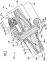
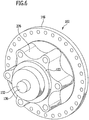
- the hub 102 which without further components in Fig. 6 includes a hub shell 122 and a wheel axle 132 which is aligned along the axis of rotation 114, wherein the wheel axle 132 is rotatably mounted about the rotation axis 114 in the hub shell 122.
- a middle region 134 of the wheel axle 132 which lies between a first end region 136 and a second end region 138 of the wheel axle 132, is rotatably mounted in the hub shell 122 and the first end region 136 and the second end region 138 of the wheel axle 132 protrude from opposite front sides 142 and 144 of the hub shell 122 out of this.
- the wheel 74 is fastened to the wheel suspension 72 with the wheel axle 132, wherein in particular the first end region 136 of the wheel axle 132 is arranged on the first dropout 96 and the second end region 138 of the wheel axle 132 is arranged on the second dropout 98.
- the hub shell 122 comprises a first annular collar 146I and a second annular collar 146II, which are offset along the axis of rotation 114 and lie at equal distances from the wheel plane 112 on different sides of the wheel plane 112, so that the first annular collar 146I is positioned between the wheel plane 112 and the front side 142 and the second annular collar 146II is positioned between the wheel plane 112 and the second front side 144.
- the annular collars 146I and 146II are provided for attachment of the spokes 108.
- spokes 108 some spokes 108I are disposed on the first annular collar 146I and the remaining spokes 108II are disposed on the second annular collar 146II, with the number of spokes 108I and the number of spokes 108II corresponding to half of the total number of spokes 108, respectively.
- the spokes 108 extend from the annular collar 146 to which they are attached to the rim 104 to which they are also secured such that the rim 104 is rotatable with the hub shell 122 about the axis of rotation 114 relative to the wheel axle 132.
- the spokes 108 run substantially in a spoke surface 148, wherein in a region of the rotation axis 114, the spoke surface 148 is spaced from the wheel plane 112, in particular at a distance with which the annular collar 146 is also spaced from the wheel plane 112, so that the Spoke surface 148 extending from the annular collar 146, and extending in the radial direction to the axis of rotation 114, the spoke surface 148 to the wheel plane 112 and in the region of the rim 104 meets the wheel plane 112 and the spoke surface 148 is rotationally symmetrical to the rotation axis 114 and cone-shaped.
- first spoke surface 148I and the second spoke surface 148II are substantially mirror-symmetrical to the wheel plane 112, so that the tip-like portions of the cone-like spoke surfaces 148I and 148II are spaced apart along the rotation axis 114 and the spoke surfaces 148I and 148II extend toward each other starting from the tip-like regions ,
- the brake device 76 comprises an actuating unit 202, a brake caliper 204, which is arranged in particular on the wheel suspension 72, and a brake disc 206 which is arranged on the hub 102, in particular on the hub shell 122.
- the actuating unit 202 such as a lever, and the brake calliper 204 via a hydraulic system 208 are connected to transmit pressure, so that by operating the actuator 202, the brake calliper 204 is actuated, whereby the brake calliper 204 cooperates braking with the brake disc 206 and thus a rotational movement of the Brake disc 206 is reduced and since the brake disc 206 is disposed on the wheel 74, thus, a rotational speed of a rotational movement of the wheel 74 is reduced.
- the hydraulic system 208 comprises a master cylinder 222 which is connected to the brake caliper 204 via a pressure line 224.
- the brake caliper 204 comprises a brake caliper housing 232 which is mounted with a first bracket 234 and a second bracket 236 on the wheel suspension 72, in particular on one of the fork legs 84, 86, for example with a brake caliper bracket 238.
- the brake caliper 204 which increases in Fig. 7 also includes a first brake pad 242 and a second brake pad 244, which are movably disposed on the brake caliper housing 232, wherein the brake pads 242 and 244 are spaced from each other, so that the brake disc 206 between the brake pads 242 and 244 is positionable.
- the first brake pad 242 is acted on by a first piston 246 and the second brake pad 244 is acted upon by a second piston 248, wherein the first piston 246 and the second piston 248 are connected to the hydraulic system 208, in particular via the pressure line 242.
- the brake disk 206 extends substantially in a brake disk plane 252, which in Fig. 8 corresponds to the representation plane, from an inner region 254 to an outer region 256, wherein the brake disc 206 to a brake disc axis 262, which is substantially perpendicular to the disc plane 252, in a direction of the brake disc axis 262 radial direction 264 from the inner region 254 to the Outside area 256 extends and the outer area 256 relative to the radial direction 264 lies radially outside of the inner area 254 and the outer area 256 in the brake disk plane 252 the inner area 254 along a circumferential direction 266 around the brake disk axis 262.
- the front brake disk 206v and the rear brake disk 206h are the same size. In a variant, it is provided that the brake discs 206v and 206h have different sizes.
- a mounting ring 272 is provided, which with a fastening element 274 to the hub 102, in particular to a holding element 276, which is formed, for example, flange-like, the hub shell 122, can be mounted so that the brake disc 206 fixed to the Hub housing 122 is connected.
- each six holes and the fastening element 274 comprises six connecting parts, which are provided for each one hole of the mounting ring 272 and a hole of the holding member 276 and so the mounting ring 272 is connected to the connecting parts of the fastening element 274 with the holding element 276.
- axle passage opening 278 Centered in the mounting ring 272 is an axle passage opening 278 through which the wheel axle 132 can pass and the brake disk axle 262 passing through the axle passage opening 278.
- a brake ring 282 which annularly surrounds the brake disk axis 262 substantially with a radius 284, is arranged, and the brake linings 242 and 244 act upon the brake ring 282 during a braking operation.
- the mounting ring 272 and the brake ring 282 are interconnected by support webs 286 wherein, for example, the support webs 286 are supported with additional support webs 288 on the mounting ring 272.
- the support webs 286 are elongated and extend from the inner region 254 to the outer region 256 of the brake disc 206, for example, the support webs 286 extend arcuately.
- Each individual support web 286 i of the support webs 286 extends longitudinally from the inner region 254 to the outer region 256 in an extension direction 292 i , wherein the extension direction 292 i extends inclined to the radial direction 264 to the brake disk axis 262.
- Each support web 286 i of the support webs 286 extends transversely to its extension direction 292 i from a first edge 294 i to a second edge 296 i , wherein a distance of the edges 294 i and 296 i is a width 298 i of the support web 286 i and the width 298 i relative to a direction transverse to the radial direction 264, in particular substantially in the direction of rotation of the brake disk axis 262, 266 is measured.
- edges 294 i , ... and 296 i , ... of the edges 294 and 296 are indicated.
- the widths 298 i of the supporting webs 286 i corresponding to a width 298 are equal. In a variant, it is provided that the widths 298 i , ... are of different sizes.
- the supporting webs 286 are arranged periodically in the direction of the circumferential direction 266, for example, the arrangement of the supporting webs 286 is n-rotationally symmetrical with respect to the brake disk axis 262, i. in that the arrangement of the webs 286 is symmetrical with respect to a rotation about the brake disk axis 262 at an angle of 360 ° / n, where n is a natural number and in the exemplary embodiment corresponds to the number N of the carrier webs 286.
- the brake device 76 operates as follows.
- the actuating unit 202 acts, for example with the lever, on the master cylinder 222 of the hydraulic system 208, whereby the master cylinder 222 generates a pressure increase in the hydraulic system 208, which is transmitted through the pressure line 224 to the brake caliper 204 by means of a hydraulic fluid, whereby the brake caliper 204 is pressed.
- the increased pressure in the hydraulic system 208 is converted into a mechanical movement of the pistons 246 and 248, whereby the first piston 246 acts on the first brake pad 242 and the second piston 248 acts on the second brake pad 244 and thereby the first brake pad 242 and the second brake pad 244 move towards each other so that the brake ring 282 positioned between the first brake pad 242 and the second brake pad 244 which rotates when the bicycle 10 is traveling, acts on each side of the first brake pad 242 and the second brake pad 244 and by the resulting friction, the rotational speed of the brake ring 282 and consequently also the rotational speed of the wheel 74 connected to the brake ring 282, is reduced.
- the sensor unit 78 comprises a sensor ring 612, which is arranged on the wheel 74, and a sensor 614, which is aligned with a scanning region 616 of the sensor ring 612 and detects this scanning region 616, in particular detects a relative movement of the scanning region 616 relative to the sensor 614.
- the sensor ring 612 extends substantially in a sensor rim axis 618 perpendicular to the sensor bead plane 622, wherein in Fig. 9 the sensor crown plane 622 substantially corresponds to the display plane and the sensor rim axis 618 extends perpendicular to the display plane, and extends in the sensor crown plane 622 from an inner region 624 to an outer region 628, wherein the inner region 624 relative to a direction to the sensor rim axis 618 radial direction 630 relative the outer region 628 lies radially inward, and wherein the inner region 624 and the outer region 628 surround the sensor rim axis 618 in a circumferential direction 632, so that in particular the outer region 628 surrounds the inner region 624 along the circumferential direction 632 around the sensor rim axis 618 in the sensor crown plane 622.
- the sensor ring 612 is formed substantially planar, so that in particular the inner region 624 and the outer region 628 of the sensor ring 612 are arranged substantially in the sensor rim axis 618.
- a mounting ring 634 is arranged, with which the sensor rim 612 can be mounted on the hub 102.
- the mounting ring 634 is formed in an analogous manner as the mounting ring 272 of the brake disc 206, so that reference may be made in full to the comments on the same.
- An axle passage opening 636 is arranged in the inner region 624 of the sensor rim 612, with the sensor rim axle 618 passing through the axle passage opening 636 and, in particular, the axle passage opening being substantially circular and centered relative to the sensor rim axle 618.
- the mounting ring 634 surrounds the axle passage opening 636 in the sensor crown plane 622 along the direction of rotation 632 around the sensor rim axis 618.
- the inner region 624 of the sensor collar 612, in particular the mounting ring 634, and the outer region of the sensor collar 612, for example the scanning region 616 of the sensor collar 612, are held by retaining webs 642.
- the retaining webs 642 extend arcuately from the inner region 624 to the outer region 628.
- the retaining webs 642 extend oblong and inclined to the radial direction to the sensor rim axis 618.
- the holding webs 642 with respect to their elongated extent, in particular with respect to the extent transverse to the direction to the sensor rim axis 618 radial direction, slightly shorter than the supporting webs 286 of the brake disc 206 with respect to their elongated extent.
- the holding webs 642 are formed substantially similar to the support webs 286 of the brake disk 206, in particular with respect to their orientation to the sensor rim axis 618 and the brake disk axis 262 radial direction, with respect to their width transverse to the axis to the axis 618 and 262 radial direction and with respect to the curvature of the arcuate formation.
- the holding webs 642 are rotationally symmetric with respect to the sensor rim axis 618, i. in that the arrangement of the holding webs 642 is symmetrical about the sensor rim axis 618 with respect to rotation at an angle of 360 ° / h, h being a natural number and in the embodiment h corresponding to the number of holding webs 642.
- holding webs 642 are additionally supported on the mounting ring 634 with additional retaining webs 644, one of the additional retaining webs 644 being provided for each of the retaining webs 642.
- the sensing region 616 of the sensor rim 612 is arranged, wherein the sensing region 616 is formed substantially annularly around the sensor rim axis 618 with a radius 646 and the annular sensing region 616 is arranged substantially centered to the sensor rim axis 618.
- the radius 646 of the scanning region 616 is smaller than the radius 284 of the brake ring 282.
- the scanning region 616 has a periodically varying structure 648, wherein the periodically varying structure 648 varies periodically along the circumferential direction 632 about the sensor rim axis 618 in one of its properties.
- the periodically varying structure 648 is formed as a toothed structure, wherein the toothed structure runs along the circumferential direction along the circumferential direction 632 around the sensor rim axis 618 in the scanning region 616.
- the toothed structure is formed by teeth 652, which extend substantially in the sensor crown plane 622 and in particular inclined to the direction to the sensor rim axis 618 radial direction, in particular the alignment of the teeth 652 is formed in an analogous manner as the orientation of the support webs 286 of the brake disc 206 to the direction of the brake disc axis 262 radial direction 264th
- the teeth 652 are elongated along an extension direction, which is oriented obliquely to the radial direction to the sensor rim axis 618.
- the teeth 652 are formed by material bridges 656, wherein an opening 658 is arranged between each of the material bridges 656.
- the material bridges 656 and the openings 658 are arranged to alternate periodically along the circumferential direction 632 about the sensor rim axis 618 and thus form a rotationally symmetrical arrangement with respect to the sensor rim axis 618 and an angle which is smaller than 360 °.
- the material bridges 656 are substantially equally shaped and arranged transversely to the circumferential direction 632 and inclined to the radial direction to the sensor rim axis 618 and are thus aligned in particular in a similar manner as the support webs 286 of the brake disc 206 to the radial direction 264 to the brake disc axis 262 aligned are.
- the apertures 658 extend inclined to the direction to the sensor rim axis 618 radial direction and extend transversely to the direction of rotation 632 and are aligned in a similar manner as the material bridges 656th
- the openings 658 have a width transversely to their elongate extent, that is to say in particular substantially in the direction of the circumferential direction 632, which is smaller than the width 298 of the carrier webs 286 of the brake disk 206.
- the material bridges 656 are designed to strongly influence a magnetic field, for example, formed from a magnetic field strongly influencing material.
- the periodically varying sequence of one of the material bridges 656, which is strongly magnetic field influencing, and one of the breakthroughs 658, which at most weakly influences a magnetic field forms a periodically varying differently magnetfeldbeeinlende structure, the strength of the magnetic field influence at a transition of one of the Material bridges 656 to one of the breakthroughs 658 changes suddenly.
- the periodically varying magnetic field influencing structure along the circumferential direction 632 around the sensor rim axis 618 has the same periodicity as the toothed structure.
- the sensor 614 detects the periodically varying structure 648 of the scanning region 616, in particular the sensor 614 detects the material bridges 656 and the openings 658, for example the transitions from the material bridges 656 to the openings 658.
- the senor 614 is embodied by way of example as a magnetic sensor so that the periodically varying magnetic field influencing structure of the scanning region 616 triggers a periodically varying signal during a relative movement relative to the sensor 614.
- the senor 614 is designed as a Hall sensor, so that different portions of the different magnetic field influencing structure of the scanning 616, in particular the arrangement of the alternating material bridges 656 and apertures 658, generate a different sized Hall voltage in the sensor 614, and thus the sensor 614 detects the periodically varying structure 648.
- the senor 614 generates a magnetic field and detects how this magnetic field is influenced by magnetic field influencing structures which are not further than a range 682 of the sensor 614 from this.
- the senor 614 comprises a sensor surface 684 to which a detection region 686, which lies outside the sensor 614 and extends substantially no further than the range 682 from the sensor surface 684, adjoins, the sensor 614 influencing magnetic field structures within the sensor Detekttechniks Kunststoffes 686 detected.
- a sensor surface 684 flows through an electric current, the sensor surface 684, wherein by the Hall effect in a sensor surface 684 passing magnetic field, for example, a periodically varying varying magnetic field influencing structure, in particular the alternately arranged material bridges 656 and apertures 658, different strong magnetic field formed itself Forming a Hall voltage perpendicular to a flow direction of the electric current and by evaluating this Hall voltage, the size of which depends on the relative position of periodically varying different magnetic field influencing structure to the sensor 614, the sensor 614, the periodically varying structure 648, in particular the material bridges 656 and the breakthroughs 658 detected.
- magnetic field for example, a periodically varying varying magnetic field influencing structure, in particular the alternately arranged material bridges 656 and apertures 658, different strong magnetic field formed itself Forming a Hall voltage perpendicular to a flow direction of the electric current and by evaluating this Hall voltage, the size of which depends on the relative position of periodically varying different magnetic field influencing structure to the sensor 614, the sensor
- the sensor 614 is arranged in a sensor region 692 of the wheel unit 12, for example on the brake caliper holder 238.
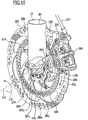
- the brake disc 206 and the sensor ring 612 are arranged adjacent to each other, in the embodiment according to the Fig. 10 to 17
- the brake disk 206 and the sensor rim 612 directly abut each other, and the brake disk axis 262 and the sensor rim axis 618 coincide with the rotation axis 114.
- the sensor 614 is arranged close to the scanning region 616 so that a partial region of the scanning region 616 is no further than the range 682 of the sensor 614 from the sensor 614 and thus this subregion of the scanning region 616 lies in the detection region 686 of the sensor 614.
- the sensor area 692 adjoins a sensor side 706 of the sensor collar 612, with the sensor side 706 facing the sensor 614 in the mounting position 702, and on a cover side 708 of the sensor collar 612 facing the sensor side 706 in the mounting position 702 Brake disc 206 arranged adjacent.
- the sensing region 616 of the sensor collar 612 abuts against the support webs 286 of the brake disk 206, as in FIG FIGS. 13 to 17 In particular, the scanning region 616 is supported on the support webs 286.
- the brake disc 206 and the sensor rim 612 are mounted to the hub 102 in the mounting position 702, for example, the brake disc 206 a mounting marking 712 and the sensor rim 612 a mounting marking 714 for indicating the relative positions of the two to each other in the mounting position 702, wherein the mounting markings 714 and 712 are formed in the embodiment as a tooth-like projection.
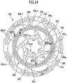
- the brake disk 206 and the sensor ring 612 are designed such that in the assembly position 702, each of the support webs 286 of the brake disk 206 completely covers a determinable number of openings 658; in the exemplary embodiment, each of the support webs 286 completely covers one of the openings 658.
- each of the first edges 294 of each of the support webs 286 abuts one of the material bridges 656 of the sensor collar 612 and also each of the second edges 296 of each of the support webs 286 abuts one of the material bridges 656 of the sensor collar 612 as in FIG Fig. 14 and 15 is shown.
- each of the edges 294 and 296 of each of the support webs 286 extends such that in the mounting position 702 in the scanning region 616, the edges 294 and 296 are each covered by one of the material bridges 656.
- the sensor 614 is located in the mounting position 702 of the sensing region 616 of the sensor rim 612 no further than the range 682 of the sensor 614 and thus the sensor 614 detects the magnetic field influencing effect of a portion of the scanning region 616, which lies in the detection range 686 of the sensor 614 and Upon rotation of the scanning region 616 with the wheel 74 of the wheel unit 12 about the rotation axis 114, the magnetic field influencing effect of the partial region of the scanning region 616, which lies in the detection region 686 of the sensor 614, is temporally periodic due to the periodically varying varying magnetic field influencing structure in the scanning region 616 different, wherein the temporal periodicity of the rotational speed of the scanning region 616 and thus depends on the rotational speed of the wheel 74 and thus determines the sensor 614, the rotational speed of the wheel 74th
- the senor 614 requires a unique signal, which is caused by a unique structure in the scanning region 616 and which may not be influenced by the voltage applied to the sensor ring 612 brake disc 206.
- Each of the material bridges 656 significantly affects a magnetic field penetrating its region since the sensing region 616 of the sensor collar 612 is formed of a magnetically influencing material.
- the influence of the magnetic field by one of the material bridges 656 is such is pronounced that the sensor 614, which is arranged in the sensor region 692, one of the edges 294, 296 of one of the support webs 286, which rests against the material bridge 656, not or at most detected slightly insignificant.
- the sensor 614 registers covered material bridges 656a against which one of the edges 294, 296 of one of the support webs 286 receives substantially the same signal as exposed material bridges 656f to which none of the support webs 286 and none of the edges 294, 296 contact.
- One of the exposed apertures 658f affects a magnetic field penetrating its region in a well-defined manner, and one of the covered apertures 658a also influences a magnetic field penetrating its region in a well-defined manner, such as one of the exposed apertures 658f and one of the apertures 658a covered a magnetic field penetrating its area can influence it differently.
- one of the openings 658 influences a magnetic field penetrating its region in a not clearly defined, noisy manner.
- the sensor 614 detects only the exposed openings 658f and the covered openings 658a a clear signal.
- the sequence of material bridges 656, exposed openings 658f and covered openings 658a is precisely defined and none of the openings 658 of one of the edges 294, 296 abuts one of the support webs 286, the sensor 614 receives a signal which is good for determining the Rotational speed of the wheel 74 is processable.
- the anti-lock brake system 18 includes a control unit 804 which is signal transmitting connected to the sensor units 78v and 78h of the front and rear wheel units 12v and 12h, and a pressure regulating unit 806 connected to the hydraulic system 208v of the front wheel unit 12v, and in a variant in an analogous manner the hydraulic system 208h of the rear wheel unit 12h is adjustably connected to the pressure in the hydraulic system 208, the control unit 804 adjusting the pressure regulating unit 806 in response to the measured rotational speeds of the front wheel 74v and the rear wheel 74h detected by the sensor units 78 and to the control unit 806 be transmitted controls.
- the control unit 804 of the anti-lock brake system 18 determines from the rotational speeds of the wheels 74v and 74h transmitted by the sensor units 78v and 78h the difference between the two rotational speeds of the wheels 74 and determines therefrom, for example, if the two rotational speeds relative to each other are too great, one of the wheels 74 is blocked, so its rotational speed compared to the rotational speed of the other wheel 74, is considerably smaller, the blocking by a strong actuation of the actuator 202 of the brake device 76 and a resulting strong braking action of the brake calliper 204 on the brake disc 206 and thus on the wheel 74 is caused.
- control unit 804 is connected, for example, with electrically conductive cables to the sensor units 78v and 78h and the sensor units 78 transmit the rotational speeds of the wheels 74 in the form of electrical pulses.
- control unit 804 is connected to the pressure regulation unit 806 with an electrically conductive cable and communicates control commands for the pressure regulation unit 806 in the form of electrical pulses along the cable.
- control unit 804 When the control unit 804 detects a wheel 74 lock, it actuates the pressure regulating unit 806, whereupon the pressure regulating unit 806 reduces the pressure in the hydraulic system 208 of the brake device 76, for example, by the pressure regulating unit 806 partially diverting hydraulic fluid from the hydraulic system 208 into a buffer ,
- the pistons 246 and 248 apply less force to the brake pads 242 and 244, and thus the brake pads 242 and 244 press less strongly on the brake disc 206, so that the friction thereon decreases and the blocking of the wheel 74 is released and the wheel 74 rolls again.
- the bicycle drive system 16 includes a sprocket 848 disposed on the hub shell 122h of the rear wheel unit 12h, a sprocket 852, and a chain 854 movably tensioned between the sprocket 848 and the sprocket 852 to allow rotational movement from the sprocket 852 the chain 854 is transmitted to the sprocket 848, as well as pedals 856 and 858, as in Fig. 1 is shown.
- the chainring 852 is rotatably movably mounted on the frame 14 and the pedals 856 and 858 are connected to the chainring 852, so that the driver who steps on the pedals 856 and 858 and thus brings the chainring 852 into rotational motion, the rear wheel 74h drives to a rotational movement, characterized in that the rotation of the chainring 852 caused by the driver is transmitted via the chain 854 to the ring gear 848 and thus to the hub shell 122h.
- an intermediate layer 902 is provided between the brake disk 206 and the sensor ring 612, which rests with a first side 904 on the sensor ring 612 and with a second side 906 against the brake disk 206, so that the sensor ring 612 in the mounting position 702 'Located adjacent to the brake disc 206 and the sensor rim 612 is supported in particular on the brake disc 206.
- FIG Fig. 20 a third embodiment of the solution according to the invention, shown in FIG Fig. 20 , Those parts which are identical to those of one of the preceding embodiments are provided with the same reference numerals, so that with respect to the description of the same reference may be made in full to the comments on the above embodiments.
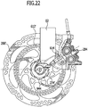
- the senor 614 'of the sensor unit 602 is disposed in the brake caliper housing 232' of the brake caliper 204 '.
- a surround 932 is formed, which comprises a surround 934, in which the sensor 614 can be mounted.
- the skirt 934 is substantially at a distance from the brake pads 242 and 244 spaced, which corresponds to the distance of the scanning portion 616 of the brake ring 282, so that the brake pads 242 and 244 are arranged cooperatively with the brake ring 282 and the sensor 614 'on the scanning region 616 is aligned.
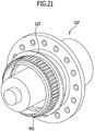
- a hub shell 122 'of the hub 102' includes a toothed ring 942 for mounting the brake disc 206 'and the sensor collar 612'.
- a fastening element 274 ' comprises a receiving region 944 for the toothed ring 942 and the brake disc 206' and the sensor ring 612 'are so with the fastening element 274' to the hub 102 'mountable.
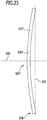
- FIG Fig. 23 a schematic radial section through a sensor ring 612 "according to the invention, those parts which are identical to those of one of the preceding embodiments are provided with the same reference numerals, so that with respect to the description thereof reference may be made in full to the statements in connection with the preceding embodiments ,
- the sensor rim 612 is substantially cup-shaped, that is, the sensor rim 612" is bent from the sensor rim axis 618 in the direction radial to the sensor rim axis 618.
- the sensor ring 612 in its outer region 628, in particular in the scanning region 616", defines the sensor rim plane 622 and the inner region 624 ", in particular the mounting ring 634", is at a distance from the sensor crown plane 622 in the axial direction relative to the sensor rim axis 618.
- the sensor ring 612 is biased against the hub 102 and force applied to the brake disk 206, so that in the assembled state, the inner region 624" and the outer region 628 of the sensor collar 612 "extend substantially in the sensor crown plane 622.
- the scanning region 616 is supported on the support webs 286 of the brake disk 206.
- FIG Fig. 24 In a sixth embodiment of a solution according to the invention, shown in FIG Fig. 24 , those parts which are identical to those of one of the preceding embodiments are provided with the same reference numerals, so that with respect to the description thereof reference may be made in full to the statements made in connection with the preceding embodiments.
- the bicycle 10 ' according to the invention comprises an auxiliary drive 902 which is supplied with energy from a power source 904 via a power transmission element 906.
- the energy source 904 is an accumulator, that is to say a rechargeable accumulator for electrical energy
- the auxiliary drive 902 is supplied with electrical current via the energy transmission element 906 in the form of a cable.
- the energy source 904 comprises a fuel cell which generates electric current and supplies the additional drive 902 with this.
- the energy source 904 comprises a solar cell which generates electrical current and supplies the auxiliary drive 902 with this.
- the auxiliary drive 902 includes an electric drive motor 912 and a chainring 852 'is integrated into the auxiliary drive 902 and rotatably connected, for example via a first shaft to the electric drive motor 912 and connected to a second shaft rotatably movable with the pedals 856 and 858, so that the electric drive motor 912 via the first shaft, the chainring 852 'in a rotational movement, and thus set the sprocket 848 in a rotational movement via the chain 854 and thus drives the rear wheel 74h and in an analogous manner, the driver of the bicycle 10' on the pedals 856 and 858 the chainring 852 'on the second shaft in a rotational movement and thus also drive the rear wheel 74h.
Landscapes
- Engineering & Computer Science (AREA)
- Mechanical Engineering (AREA)
- Transportation (AREA)
- Chemical & Material Sciences (AREA)
- Combustion & Propulsion (AREA)
- Physics & Mathematics (AREA)
- General Physics & Mathematics (AREA)
- Fluid Mechanics (AREA)
- Braking Arrangements (AREA)
- Regulating Braking Force (AREA)
- Force Measurement Appropriate To Specific Purposes (AREA)
Claims (17)
- Unité de roue (12) pour une bicyclette (10) comprenant un moyeu (102) et une jante (104), laquelle est agencée mobile en rotation autour d'un axe de rotation (114), dans laquelle le moyeu (102) et la jante (104) sont reliés l'un à l'autre par des rayons (108), avec un disque de frein (206) et une bague capteur (612),
caractérisée en ce que le disque de frein (206) et la bague capteur (612) avec une zone de balayage (616) sont agencés au niveau du moyeu (102) et que la bague capteur (612) est agencée de manière à être appliquée contre le disque de frein (206). - Unité de roue (12) selon la revendication 1, caractérisée en ce que la bague capteur (612) s'appuie sur le disque de frein (206).
- Unité de roue (12) selon l'une quelconque des revendications précédentes, caractérisée en ce que la bague capteur (612) s'applique directement contre le disque de frein (206).
- Unité de roue (12) selon l'une quelconque des revendications précédentes, caractérisée en ce qu'une couche intermédiaire (902) est agencée entre la bague capteur (612) et le disque de frein (206).
- Unité de roue (12) selon l'une quelconque des revendications précédentes, caractérisée en ce que le disque de frein (206) comprend plusieurs branches porteuses (286) qui portent une bague de freinage (282), qu'en particulier N branches porteuses (286) sont agencées au niveau du disque de frein (206) et l'agencement des branches porteuses (286) est symétrique en rotation avec un angle 360°/N par rapport à une rotation autour d'un axe de disque de frein (262).
- Unité de roue (12) selon l'une quelconque des revendications précédentes, caractérisée en ce que la bague capteur (612) s'étend sensiblement dans un plan de bague capteur (622), lequel s'étend perpendiculairement à un axe de bague capteur (618), qu'en particulier dans un état non monté, une zone intérieure (624) de la bague capteur (612) est distante du plan de bague capteur (622), lequel est défini ce faisant par une zone extérieure (628) de la bague capteur (612).
- Unité de roue (12) selon l'une quelconque des revendications précédentes, caractérisée en ce que la zone extérieure (628) de la bague capteur (612) est disposée de manière à être contre le disque de frein (206) sous l'effet d'une force.
- Unité de roue (12) selon l'une quelconque des revendications précédentes, caractérisée en ce que la zone de balayage (616) est agencée pour reposer contre les branches porteuses (286), qu'en particulier la zone de balayage (616) s'appuie sur les branches porteuses (286) du disque de frein (206).
- Unité de roue (12) selon l'une quelconque des revendications précédentes, caractérisée en ce que la zone de balayage (616) présente une structure périodiquement variable (648) le long de la direction périphérique (632) autour de l'axe de bague capteur (618), qu'en particulier la structure périodiquement variable (648) dans la zone de balayage (616) est symétrique en rotation avec un angle 360°/kN par rapport à une rotation autour de l'axe de bague capteur (618), dans laquelle kN correspond au nombre N des branches porteuses (286) du disque de frein (206) ou à un multiple entier de celui-ci.
- Unité de roue (12) selon l'une quelconque des revendications précédentes, caractérisée en ce que la structure périodiquement variable (648) est réalisée de manière à influencer plus ou moins fortement le champ magnétique de façon périodiquement variable le long de la direction périphérique autour de l'axe de bague capteur (618).
- Unité de roue (12) selon l'une quelconque des revendications précédentes, caractérisée en ce que la structure périodiquement variable (648) est réalisée par des passages (658) et des ponts de matériau (656) agencés de manière à s'alterner régulièrement, qu'en particulier les passages (658) s'étendent de manière oblongue dans une direction (630) radiale à l'axe de bague capteur (618), qu' en particulier mN passages (658) et mN ponts de matériau (656) sont agencés dans la zone de balayage (616), dans laquelle mN correspond au nombre N des branches porteuses (286) du disque de frein (206) ou à un multiple entier de celui-ci.
- Unité de roue (12) selon l'une quelconque des revendications précédentes, caractérisée en ce que les passages (658) et les ponts de matériau (656) sont agencés symétriques en rotation avec un angle 360°/IN par rapport à une rotation autour de l'axe de bague capteur (618), dans laquelle IN correspond au nombre N des branches porteuses (286) du disque de frein (206) ou à un multiple entier de celui-ci, qu'en particulier les passages (658) et les ponts de matériau (656) sont agencés périodiquement entre les branches porteuses (286) du disque de frein (206) le long de la direction périphérique (116) autour de l'axe de rotation (114), qu'en particulier une largeur des passages (658) transversalement à la direction radiale à l'axe de bague de capteur (618) est inférieure à une largeur des branches porteuses (286) du disque de frein (206) transversalement à la direction radiale à l'axe de disque de frein (252), qu'en particulier chaque bord (294, 296) de chacune des branches porteuses (286) est agencé au niveau d'une zone de la zone de balayage (616) influençant fortement un champ magnétique, qu'en particulier un bord (294, 296) de chacune des branches porteuses (286) est recouvert par un des ponts de matériau (656) dans la zone de balayage (616).
- Unité de roue (12) selon l'une quelconque des revendications précédentes, caractérisée en ce que les branches porteuses (286) du disque de frein (206) sont agencées périodiquement le long de la direction périphérique (632) autour de l'axe de rotation (114) par rapport à la structure périodiquement variable (648) de la zone de balayage (616), qu'en particulier chacune des branches porteuses (286) recouvre entièrement au moins un des passages (658), qu'en particulier chacun des passages (658) soit est recouvert entièrement par une branche porteuse (286) soit est exposé, qu'en particulier les passages recouverts (658a) et les passages exposés (658f) sont agencés de manière périodique le long de la direction périphérique (612) autour de l'axe de bague capteur (618).
- Unité de roue (12) selon l'une quelconque des revendications précédentes, caractérisée en ce que des branches de retenue (642) retiennent la zone de balayage (616) au niveau d'une bague de montage (634), qu'en particulier la bague capteur (612) et le disque de frein (206) sont agencés au niveau du moyeu (102) de sorte que les branches porteuses (286) du disque de frein (206) et les branches de retenue (642) de la bague capteur (612) se recouvrent dans une direction axiale à l'axe de rotation (114).
- Unité de roue (12) selon l'une quelconque des revendications précédentes, caractérisée en ce que l'unité de roue comprend un capteur (614) pour la détection de la zone de balayage, que l'unité de roue (12) comprend un étrier de frein (204), lequel coopère par freinage avec le disque de frein (206), qu'en particulier l'étrier de frein (204) comprend une bordure (904), dans laquelle le capteur (614) est agencé.
- Unité de roue (12) selon l'une quelconque des revendications précédentes, caractérisée en ce que l'unité de roue comprend un capteur (614) pour la détection de la zone de balayage, que le moyeu (102) est agencé mobile en rotation autour d'un axe de rotation (114) au niveau d'une suspension de roue (72) de l'unité de roue (12), qu'en particulier le capteur (614) est agencé au niveau de la suspension de roue (72) .
- Bicyclette (10) comprenant une unité de roue avant (12v) et une unité de roue arrière (12h), lesquelles sont reliées l'une à l'autre par un cadre (14), caractérisée en ce qu'au moins une des unités de roue (12v, 12h) de la bicyclette (10) est réalisée selon l'une quelconque des revendications 1 à 16.
Priority Applications (1)
| Application Number | Priority Date | Filing Date | Title |
|---|---|---|---|
| EP19200544.5A EP3611086B1 (fr) | 2015-11-27 | 2016-11-22 | Unité de roue avec un frein à disque et une bague capteur |
Applications Claiming Priority (1)
| Application Number | Priority Date | Filing Date | Title |
|---|---|---|---|
| DE102015120656.0A DE102015120656A1 (de) | 2015-11-27 | 2015-11-27 | Radeinheit |
Related Child Applications (1)
| Application Number | Title | Priority Date | Filing Date |
|---|---|---|---|
| EP19200544.5A Division EP3611086B1 (fr) | 2015-11-27 | 2016-11-22 | Unité de roue avec un frein à disque et une bague capteur |
Publications (2)
| Publication Number | Publication Date |
|---|---|
| EP3176064A1 EP3176064A1 (fr) | 2017-06-07 |
| EP3176064B1 true EP3176064B1 (fr) | 2019-10-02 |
Family
ID=57389332
Family Applications (2)
| Application Number | Title | Priority Date | Filing Date |
|---|---|---|---|
| EP16200038.4A Active EP3176064B1 (fr) | 2015-11-27 | 2016-11-22 | Unité de roue avec un frein à disque et une bague capteur |
| EP19200544.5A Revoked EP3611086B1 (fr) | 2015-11-27 | 2016-11-22 | Unité de roue avec un frein à disque et une bague capteur |
Family Applications After (1)
| Application Number | Title | Priority Date | Filing Date |
|---|---|---|---|
| EP19200544.5A Revoked EP3611086B1 (fr) | 2015-11-27 | 2016-11-22 | Unité de roue avec un frein à disque et une bague capteur |
Country Status (4)
| Country | Link |
|---|---|
| US (1) | US10556463B2 (fr) |
| EP (2) | EP3176064B1 (fr) |
| DE (1) | DE102015120656A1 (fr) |
| TW (1) | TWI697434B (fr) |
Cited By (2)
| Publication number | Priority date | Publication date | Assignee | Title |
|---|---|---|---|---|
| DE202024105856U1 (de) | 2024-10-11 | 2024-11-13 | Zf Friedrichshafen Ag | Radeinheit für ein Fahrrad und Fahrrad |
| DE102024209919A1 (de) | 2024-10-11 | 2026-04-16 | Zf Friedrichshafen Ag | Radeinheit für ein Fahrrad und Fahrrad |
Families Citing this family (23)
| Publication number | Priority date | Publication date | Assignee | Title |
|---|---|---|---|---|
| US10500897B2 (en) * | 2015-03-31 | 2019-12-10 | Honda Motor Co., Ltd. | Supporting structure of wheel speed sensor |
| IT201600111381A1 (it) * | 2016-11-04 | 2018-05-04 | Piaggio & C Spa | Struttura di supporto per sensore di ruota fonica |
| JP6720094B2 (ja) * | 2017-01-13 | 2020-07-08 | 株式会社シマノ | 自転車用磁気発生装置およびディスクブレーキアダプタ |
| DE102017110946A1 (de) * | 2017-05-19 | 2018-11-22 | Gustav Magenwirth Gmbh & Co. Kg | Radeinheit für ein Fahrzeug |
| TWM553421U (zh) * | 2017-07-31 | 2017-12-21 | Giant Electric Vehicle Kunshan Co Ltd | 自行車速度感應器 |
| US10605320B2 (en) * | 2017-08-09 | 2020-03-31 | Shimano Inc. | Disc brake rotor assembly and brake system |
| JP7202776B2 (ja) * | 2017-11-09 | 2023-01-12 | 株式会社シマノ | 回転検出装置およびこれを備える制動装置 |
| EP3492275A1 (fr) * | 2017-11-29 | 2019-06-05 | Dndr Bvba | Moyeu de roue comportant des composants d'un système de frein désengageable |
| JP6736596B2 (ja) * | 2018-03-16 | 2020-08-05 | 本田技研工業株式会社 | 車両 |
| EP3590812B1 (fr) * | 2018-07-05 | 2022-09-07 | Winora-Staiger GmbH | Système de mesure incrémental pour une bicyclette, bicyclette, moyen émetteur de signal et procédé de fabrication |
| TWI707799B (zh) * | 2020-03-27 | 2020-10-21 | 彥豪金屬工業股份有限公司 | 自行車防鎖死煞車裝置控制方法及自行車防鎖死煞車組件 |
| DE102020205030A1 (de) * | 2020-04-21 | 2021-10-21 | Shimano Inc. | Scheibenbremsrotoranordnung |
| DE102020112062A1 (de) | 2020-05-05 | 2021-11-11 | Schaeffler Technologies AG & Co. KG | Bremsvorrichtung für ein Fahrzeug und Fahrzeug mit der Bremsvorrichtung |
| US20210405082A1 (en) * | 2020-06-30 | 2021-12-30 | Sram, Llc | Speed sensing devices and systems for a bicycle |
| US11524741B2 (en) * | 2020-07-16 | 2022-12-13 | Shimano Inc. | Sensor wheel and disc brake apparatus |
| JP7657556B2 (ja) | 2020-09-03 | 2025-04-07 | 株式会社シマノ | 車輪速センサおよび車輪速センサ用の治具 |
| CN116766825A (zh) * | 2020-12-25 | 2023-09-19 | 株式会社岛野 | 用于人力车辆的电气部件 |
| CN214985873U (zh) * | 2021-02-07 | 2021-12-03 | 深圳市美大行科技有限公司 | 碟刹装置及自行车 |
| US20220281553A1 (en) * | 2021-03-08 | 2022-09-08 | Sram, Llc | Speed sensing devices and systems for a bicycle |
| CN117858807A (zh) | 2021-08-24 | 2024-04-09 | 什拉姆有限责任公司 | 用于电动助力自行车的轮单元和电动助力自行车 |
| TWI808585B (zh) * | 2021-12-29 | 2023-07-11 | 彥豪金屬工業股份有限公司 | 自行車碟煞卡鉗及自行車組件 |
| DE102022202716A1 (de) | 2022-03-21 | 2023-08-03 | Zf Friedrichshafen Ag | Messringelement für ein Messsystem für ein Mikromobilitätsfahrzeug, Messsystem und Mikromobilitätsfahrzeug |
| EP4357152B1 (fr) * | 2022-10-19 | 2025-08-20 | Hochschule Für Angewandte Wissenschaften München | Système de freinage antiblocage |
Citations (1)
| Publication number | Priority date | Publication date | Assignee | Title |
|---|---|---|---|---|
| DE102014005527A1 (de) * | 2014-04-11 | 2015-10-15 | Daniel Gordon Erler | Elektrisches Fahrrad-ABS-System, das Bestandteile eines elektrischen Kraftrad-ABS-Systems enthält, für die Anwendung auf Fahrrädern und Elektrofahrrädern "Pedelecs", Liegerädern und Liegedreirädern, sowie ein Gewichtsschieberegler, Funktionen am Bordcomputer sowie Liegedreirädern mit drei unabhängigen Bremsen. |
Family Cites Families (24)
| Publication number | Priority date | Publication date | Assignee | Title |
|---|---|---|---|---|
| EP0971150B1 (fr) | 1998-07-06 | 2004-01-28 | Shimano Inc. | Méthode de refroidissement pour frein à disque de bicyclette |
| JP2001165949A (ja) * | 1999-09-30 | 2001-06-22 | Honda Motor Co Ltd | 車輪速度検出装置 |
| JP2003072653A (ja) * | 2001-09-04 | 2003-03-12 | Honda Motor Co Ltd | 折り畳み二輪車両 |
| JP4414257B2 (ja) * | 2004-03-23 | 2010-02-10 | 本田技研工業株式会社 | 自動二輪車における車輪速センサ取付け構造 |
| JP4728618B2 (ja) * | 2004-09-30 | 2011-07-20 | 本田技研工業株式会社 | パルサリングの取付構造 |
| JP4520333B2 (ja) * | 2005-03-09 | 2010-08-04 | 本田技研工業株式会社 | 車速センサの取付構造 |
| JP4690124B2 (ja) | 2005-06-27 | 2011-06-01 | 川崎重工業株式会社 | 自動二輪車の車速検出装置 |
| US20080111342A1 (en) * | 2006-11-09 | 2008-05-15 | Volkswagen Of America, Inc. | Bicycle having an antilock brake |
| JP4724646B2 (ja) * | 2006-11-13 | 2011-07-13 | 本田技研工業株式会社 | 自動二輪車の車輪速センサ取付構造 |
| JP5422127B2 (ja) | 2008-01-23 | 2014-02-19 | 本田技研工業株式会社 | 自動二輪車 |
| DE102008019469B4 (de) * | 2008-04-18 | 2023-09-21 | Robert Bosch Gmbh | Überschlagschutzsystem für Zweiräder |
| TWM416595U (en) * | 2008-09-24 | 2011-11-21 | Sheng-Chang Shieh | Brake-actuating electrical charging mechanism for electrically powered motorcycle and bicycle |
| JP5532727B2 (ja) * | 2009-08-03 | 2014-06-25 | サンスター技研株式会社 | ブレーキディスク |
| TW201117986A (en) * | 2009-11-23 | 2011-06-01 | Kwang Yang Motor Co | Structure of reading disc for anti-brake system of motorcycle |
| EP3312442A3 (fr) * | 2010-08-26 | 2018-07-18 | Gustav Magenwirth GmbH & Co. KG | Frein à disque hydraulique |
| JP2012141184A (ja) | 2010-12-28 | 2012-07-26 | Honda Motor Co Ltd | パルサーリングおよび鞍乗り型車両 |
| JP5969179B2 (ja) * | 2011-07-31 | 2016-08-17 | 本田技研工業株式会社 | 車輪速センサの取付構造 |
| JP5990045B2 (ja) * | 2012-06-26 | 2016-09-07 | 本田技研工業株式会社 | 鞍乗り型車両 |
| DE102012222058B4 (de) | 2012-12-03 | 2024-03-21 | Robert Bosch Gmbh | Hydraulisches Bremssystem für Zweiräder |
| JP5783994B2 (ja) * | 2012-12-25 | 2015-09-24 | 本田技研工業株式会社 | 車輪速センサーリング取り付け構造 |
| JP6002080B2 (ja) | 2013-04-26 | 2016-10-05 | 本田技研工業株式会社 | 車輪速検出機構 |
| BR112015032748A2 (pt) * | 2013-07-01 | 2017-07-25 | Yamaha Motor Co Ltd | veículo |
| US9573648B2 (en) * | 2014-07-16 | 2017-02-21 | Ford Global Technologies, Llc | Wheel coupling |
| CN204606110U (zh) | 2015-05-04 | 2015-09-02 | 张小红 | 带传感器和显控仪表的碟刹 |
-
2015
- 2015-11-27 DE DE102015120656.0A patent/DE102015120656A1/de not_active Ceased
-
2016
- 2016-11-09 TW TW105136432A patent/TWI697434B/zh not_active IP Right Cessation
- 2016-11-22 EP EP16200038.4A patent/EP3176064B1/fr active Active
- 2016-11-22 US US15/358,992 patent/US10556463B2/en active Active
- 2016-11-22 EP EP19200544.5A patent/EP3611086B1/fr not_active Revoked
Patent Citations (1)
| Publication number | Priority date | Publication date | Assignee | Title |
|---|---|---|---|---|
| DE102014005527A1 (de) * | 2014-04-11 | 2015-10-15 | Daniel Gordon Erler | Elektrisches Fahrrad-ABS-System, das Bestandteile eines elektrischen Kraftrad-ABS-Systems enthält, für die Anwendung auf Fahrrädern und Elektrofahrrädern "Pedelecs", Liegerädern und Liegedreirädern, sowie ein Gewichtsschieberegler, Funktionen am Bordcomputer sowie Liegedreirädern mit drei unabhängigen Bremsen. |
Cited By (2)
| Publication number | Priority date | Publication date | Assignee | Title |
|---|---|---|---|---|
| DE202024105856U1 (de) | 2024-10-11 | 2024-11-13 | Zf Friedrichshafen Ag | Radeinheit für ein Fahrrad und Fahrrad |
| DE102024209919A1 (de) | 2024-10-11 | 2026-04-16 | Zf Friedrichshafen Ag | Radeinheit für ein Fahrrad und Fahrrad |
Also Published As
| Publication number | Publication date |
|---|---|
| US20170151833A1 (en) | 2017-06-01 |
| EP3611086A1 (fr) | 2020-02-19 |
| EP3611086B1 (fr) | 2024-02-14 |
| TWI697434B (zh) | 2020-07-01 |
| DE102015120656A1 (de) | 2017-06-01 |
| EP3176064A1 (fr) | 2017-06-07 |
| US10556463B2 (en) | 2020-02-11 |
| TW201722779A (zh) | 2017-07-01 |
Similar Documents
| Publication | Publication Date | Title |
|---|---|---|
| EP3611086B1 (fr) | Unité de roue avec un frein à disque et une bague capteur | |
| DE102015120657B4 (de) | Fahrrad | |
| EP1192058B1 (fr) | Pont comportant un corps de pont situe sous l'essieu | |
| DE602005003495T2 (de) | Befestigungsanordnung für Radgeschwindigkeitssensor in Motorrad | |
| DE112011101658T5 (de) | Hinterachsensystem für ein Fahrrad | |
| DE69515761T2 (de) | Scheibenbremse wobei die Sattelreaktion auf eine am Rad befestigte Stützachse einwirkt, vorzugsweise für Motorradvorderräder mit einer peripherischen, ringförmigen Scheibe | |
| EP3403911A1 (fr) | Unité roue pour un véhicule | |
| DE60201470T2 (de) | Fahrradscheibenbremsnabe | |
| EP2266817B1 (fr) | Palier de roue pour axes de véhicules | |
| DE102011007110A1 (de) | Radlager-Baugruppe eines Fahrzeugs | |
| EP3450200B1 (fr) | Unité de transmission de moyeu de roue pour un moyeu de roue d'un véhicule, moyeu de roue et véhicule à entraînement auxiliaire | |
| EP2386844B1 (fr) | Capteur de couple | |
| EP2148110B1 (fr) | Revêtement pour le disque de frein d'un frein à disques de véhicule | |
| DE102010023355A1 (de) | Anordnung zur Drehmomentmessung und Fahrrad mit einer solchen Anordnung | |
| EP4134564B1 (fr) | Dispositif de fixation d'un frein à disque pourvu d'un capteur de vitesse | |
| DE102022131767A1 (de) | Bremsträger für Fahrräder | |
| EP3986776B1 (fr) | Système de freinage pour véhicule, véhicule avec ledit système de freinage | |
| DE102021130656A1 (de) | Vorrichtung mit wenigstens einer Sensoreinrichtung zur Erfassung von Messdaten über eine Relativbewegung und Maßstabeinrichtung | |
| DE102019002629A1 (de) | Fahrzeugbremse | |
| DE102023100953A1 (de) | Flatmount-Bremssattel für Fahrrad | |
| DE19627402C2 (de) | Vorrichtung zur Erfassung der Antriebskraft eines durch Muskelkraft betriebenen Geräts | |
| DE102014210522A1 (de) | Drehzahlsensor mit wesentlichem Bauteil als Impulsgeber | |
| DE102024209919A1 (de) | Radeinheit für ein Fahrrad und Fahrrad | |
| DE102018221573A1 (de) | Bremsscheibe für eine Fahrzeug-Scheibenbremse | |
| DE202024105856U1 (de) | Radeinheit für ein Fahrrad und Fahrrad |
Legal Events
| Date | Code | Title | Description |
|---|---|---|---|
| AK | Designated contracting states |
Kind code of ref document: A1 Designated state(s): AL AT BE BG CH CY CZ DE DK EE ES FI FR GB GR HR HU IE IS IT LI LT LU LV MC MK MT NL NO PL PT RO RS SE SI SK SM TR |
|
| AX | Request for extension of the european patent |
Extension state: BA ME |
|
| PUAI | Public reference made under article 153(3) epc to a published international application that has entered the european phase |
Free format text: ORIGINAL CODE: 0009012 |
|
| STAA | Information on the status of an ep patent application or granted ep patent |
Free format text: STATUS: THE APPLICATION HAS BEEN PUBLISHED |
|
| STAA | Information on the status of an ep patent application or granted ep patent |
Free format text: STATUS: REQUEST FOR EXAMINATION WAS MADE |
|
| 17P | Request for examination filed |
Effective date: 20171204 |
|
| RBV | Designated contracting states (corrected) |
Designated state(s): AL AT BE BG CH CY CZ DE DK EE ES FI FR GB GR HR HU IE IS IT LI LT LU LV MC MK MT NL NO PL PT RO RS SE SI SK SM TR |
|
| STAA | Information on the status of an ep patent application or granted ep patent |
Free format text: STATUS: EXAMINATION IS IN PROGRESS |
|
| 17Q | First examination report despatched |
Effective date: 20180219 |
|
| GRAP | Despatch of communication of intention to grant a patent |
Free format text: ORIGINAL CODE: EPIDOSNIGR1 |
|
| STAA | Information on the status of an ep patent application or granted ep patent |
Free format text: STATUS: GRANT OF PATENT IS INTENDED |
|
| INTG | Intention to grant announced |
Effective date: 20190509 |
|
| GRAS | Grant fee paid |
Free format text: ORIGINAL CODE: EPIDOSNIGR3 |
|
| GRAA | (expected) grant |
Free format text: ORIGINAL CODE: 0009210 |
|
| STAA | Information on the status of an ep patent application or granted ep patent |
Free format text: STATUS: THE PATENT HAS BEEN GRANTED |
|
| TPAC | Observations filed by third parties |
Free format text: ORIGINAL CODE: EPIDOSNTIPA |
|
| AK | Designated contracting states |
Kind code of ref document: B1 Designated state(s): AL AT BE BG CH CY CZ DE DK EE ES FI FR GB GR HR HU IE IS IT LI LT LU LV MC MK MT NL NO PL PT RO RS SE SI SK SM TR |
|
| REG | Reference to a national code |
Ref country code: GB Ref legal event code: FG4D Free format text: NOT ENGLISH |
|
| REG | Reference to a national code |
Ref country code: CH Ref legal event code: EP Ref country code: AT Ref legal event code: REF Ref document number: 1185886 Country of ref document: AT Kind code of ref document: T Effective date: 20191015 |
|
| REG | Reference to a national code |
Ref country code: DE Ref legal event code: R096 Ref document number: 502016006877 Country of ref document: DE |
|
| REG | Reference to a national code |
Ref country code: IE Ref legal event code: FG4D Free format text: LANGUAGE OF EP DOCUMENT: GERMAN |
|
| REG | Reference to a national code |
Ref country code: NL Ref legal event code: MP Effective date: 20191002 |
|
| REG | Reference to a national code |
Ref country code: LT Ref legal event code: MG4D |
|
| PG25 | Lapsed in a contracting state [announced via postgrant information from national office to epo] |
Ref country code: ES Free format text: LAPSE BECAUSE OF FAILURE TO SUBMIT A TRANSLATION OF THE DESCRIPTION OR TO PAY THE FEE WITHIN THE PRESCRIBED TIME-LIMIT Effective date: 20191002 Ref country code: LT Free format text: LAPSE BECAUSE OF FAILURE TO SUBMIT A TRANSLATION OF THE DESCRIPTION OR TO PAY THE FEE WITHIN THE PRESCRIBED TIME-LIMIT Effective date: 20191002 Ref country code: NL Free format text: LAPSE BECAUSE OF FAILURE TO SUBMIT A TRANSLATION OF THE DESCRIPTION OR TO PAY THE FEE WITHIN THE PRESCRIBED TIME-LIMIT Effective date: 20191002 Ref country code: PT Free format text: LAPSE BECAUSE OF FAILURE TO SUBMIT A TRANSLATION OF THE DESCRIPTION OR TO PAY THE FEE WITHIN THE PRESCRIBED TIME-LIMIT Effective date: 20200203 Ref country code: FI Free format text: LAPSE BECAUSE OF FAILURE TO SUBMIT A TRANSLATION OF THE DESCRIPTION OR TO PAY THE FEE WITHIN THE PRESCRIBED TIME-LIMIT Effective date: 20191002 Ref country code: BG Free format text: LAPSE BECAUSE OF FAILURE TO SUBMIT A TRANSLATION OF THE DESCRIPTION OR TO PAY THE FEE WITHIN THE PRESCRIBED TIME-LIMIT Effective date: 20200102 Ref country code: PL Free format text: LAPSE BECAUSE OF FAILURE TO SUBMIT A TRANSLATION OF THE DESCRIPTION OR TO PAY THE FEE WITHIN THE PRESCRIBED TIME-LIMIT Effective date: 20191002 Ref country code: GR Free format text: LAPSE BECAUSE OF FAILURE TO SUBMIT A TRANSLATION OF THE DESCRIPTION OR TO PAY THE FEE WITHIN THE PRESCRIBED TIME-LIMIT Effective date: 20200103 Ref country code: NO Free format text: LAPSE BECAUSE OF FAILURE TO SUBMIT A TRANSLATION OF THE DESCRIPTION OR TO PAY THE FEE WITHIN THE PRESCRIBED TIME-LIMIT Effective date: 20200102 Ref country code: SE Free format text: LAPSE BECAUSE OF FAILURE TO SUBMIT A TRANSLATION OF THE DESCRIPTION OR TO PAY THE FEE WITHIN THE PRESCRIBED TIME-LIMIT Effective date: 20191002 Ref country code: LV Free format text: LAPSE BECAUSE OF FAILURE TO SUBMIT A TRANSLATION OF THE DESCRIPTION OR TO PAY THE FEE WITHIN THE PRESCRIBED TIME-LIMIT Effective date: 20191002 |
|
| PG25 | Lapsed in a contracting state [announced via postgrant information from national office to epo] |
Ref country code: RS Free format text: LAPSE BECAUSE OF FAILURE TO SUBMIT A TRANSLATION OF THE DESCRIPTION OR TO PAY THE FEE WITHIN THE PRESCRIBED TIME-LIMIT Effective date: 20191002 Ref country code: HR Free format text: LAPSE BECAUSE OF FAILURE TO SUBMIT A TRANSLATION OF THE DESCRIPTION OR TO PAY THE FEE WITHIN THE PRESCRIBED TIME-LIMIT Effective date: 20191002 Ref country code: IS Free format text: LAPSE BECAUSE OF FAILURE TO SUBMIT A TRANSLATION OF THE DESCRIPTION OR TO PAY THE FEE WITHIN THE PRESCRIBED TIME-LIMIT Effective date: 20200224 Ref country code: CZ Free format text: LAPSE BECAUSE OF FAILURE TO SUBMIT A TRANSLATION OF THE DESCRIPTION OR TO PAY THE FEE WITHIN THE PRESCRIBED TIME-LIMIT Effective date: 20191002 |
|
| PG25 | Lapsed in a contracting state [announced via postgrant information from national office to epo] |
Ref country code: AL Free format text: LAPSE BECAUSE OF FAILURE TO SUBMIT A TRANSLATION OF THE DESCRIPTION OR TO PAY THE FEE WITHIN THE PRESCRIBED TIME-LIMIT Effective date: 20191002 |
|
| REG | Reference to a national code |
Ref country code: CH Ref legal event code: PL |
|
| REG | Reference to a national code |
Ref country code: DE Ref legal event code: R097 Ref document number: 502016006877 Country of ref document: DE |
|
| PG2D | Information on lapse in contracting state deleted |
Ref country code: IS |
|
| PG25 | Lapsed in a contracting state [announced via postgrant information from national office to epo] |
Ref country code: RO Free format text: LAPSE BECAUSE OF FAILURE TO SUBMIT A TRANSLATION OF THE DESCRIPTION OR TO PAY THE FEE WITHIN THE PRESCRIBED TIME-LIMIT Effective date: 20191002 Ref country code: LU Free format text: LAPSE BECAUSE OF NON-PAYMENT OF DUE FEES Effective date: 20191122 Ref country code: CH Free format text: LAPSE BECAUSE OF NON-PAYMENT OF DUE FEES Effective date: 20191130 Ref country code: MC Free format text: LAPSE BECAUSE OF FAILURE TO SUBMIT A TRANSLATION OF THE DESCRIPTION OR TO PAY THE FEE WITHIN THE PRESCRIBED TIME-LIMIT Effective date: 20191002 Ref country code: DK Free format text: LAPSE BECAUSE OF FAILURE TO SUBMIT A TRANSLATION OF THE DESCRIPTION OR TO PAY THE FEE WITHIN THE PRESCRIBED TIME-LIMIT Effective date: 20191002 Ref country code: LI Free format text: LAPSE BECAUSE OF NON-PAYMENT OF DUE FEES Effective date: 20191130 Ref country code: EE Free format text: LAPSE BECAUSE OF FAILURE TO SUBMIT A TRANSLATION OF THE DESCRIPTION OR TO PAY THE FEE WITHIN THE PRESCRIBED TIME-LIMIT Effective date: 20191002 Ref country code: IS Free format text: LAPSE BECAUSE OF FAILURE TO SUBMIT A TRANSLATION OF THE DESCRIPTION OR TO PAY THE FEE WITHIN THE PRESCRIBED TIME-LIMIT Effective date: 20200202 |
|
| PLBE | No opposition filed within time limit |
Free format text: ORIGINAL CODE: 0009261 |
|
| STAA | Information on the status of an ep patent application or granted ep patent |
Free format text: STATUS: NO OPPOSITION FILED WITHIN TIME LIMIT |
|
| REG | Reference to a national code |
Ref country code: BE Ref legal event code: MM Effective date: 20191130 |
|
| PG25 | Lapsed in a contracting state [announced via postgrant information from national office to epo] |
Ref country code: SK Free format text: LAPSE BECAUSE OF FAILURE TO SUBMIT A TRANSLATION OF THE DESCRIPTION OR TO PAY THE FEE WITHIN THE PRESCRIBED TIME-LIMIT Effective date: 20191002 Ref country code: SM Free format text: LAPSE BECAUSE OF FAILURE TO SUBMIT A TRANSLATION OF THE DESCRIPTION OR TO PAY THE FEE WITHIN THE PRESCRIBED TIME-LIMIT Effective date: 20191002 |
|
| 26N | No opposition filed |
Effective date: 20200703 |
|
| PG25 | Lapsed in a contracting state [announced via postgrant information from national office to epo] |
Ref country code: IE Free format text: LAPSE BECAUSE OF NON-PAYMENT OF DUE FEES Effective date: 20191122 |
|
| PG25 | Lapsed in a contracting state [announced via postgrant information from national office to epo] |
Ref country code: SI Free format text: LAPSE BECAUSE OF FAILURE TO SUBMIT A TRANSLATION OF THE DESCRIPTION OR TO PAY THE FEE WITHIN THE PRESCRIBED TIME-LIMIT Effective date: 20191002 Ref country code: BE Free format text: LAPSE BECAUSE OF NON-PAYMENT OF DUE FEES Effective date: 20191130 |
|
| PG25 | Lapsed in a contracting state [announced via postgrant information from national office to epo] |
Ref country code: CY Free format text: LAPSE BECAUSE OF FAILURE TO SUBMIT A TRANSLATION OF THE DESCRIPTION OR TO PAY THE FEE WITHIN THE PRESCRIBED TIME-LIMIT Effective date: 20191002 |
|
| PG25 | Lapsed in a contracting state [announced via postgrant information from national office to epo] |
Ref country code: HU Free format text: LAPSE BECAUSE OF FAILURE TO SUBMIT A TRANSLATION OF THE DESCRIPTION OR TO PAY THE FEE WITHIN THE PRESCRIBED TIME-LIMIT; INVALID AB INITIO Effective date: 20161122 Ref country code: MT Free format text: LAPSE BECAUSE OF FAILURE TO SUBMIT A TRANSLATION OF THE DESCRIPTION OR TO PAY THE FEE WITHIN THE PRESCRIBED TIME-LIMIT Effective date: 20191002 |
|
| PG25 | Lapsed in a contracting state [announced via postgrant information from national office to epo] |
Ref country code: TR Free format text: LAPSE BECAUSE OF FAILURE TO SUBMIT A TRANSLATION OF THE DESCRIPTION OR TO PAY THE FEE WITHIN THE PRESCRIBED TIME-LIMIT Effective date: 20191002 |
|
| PG25 | Lapsed in a contracting state [announced via postgrant information from national office to epo] |
Ref country code: MK Free format text: LAPSE BECAUSE OF FAILURE TO SUBMIT A TRANSLATION OF THE DESCRIPTION OR TO PAY THE FEE WITHIN THE PRESCRIBED TIME-LIMIT Effective date: 20191002 |
|
| P01 | Opt-out of the competence of the unified patent court (upc) registered |
Effective date: 20230521 |
|
| PGFP | Annual fee paid to national office [announced via postgrant information from national office to epo] |
Ref country code: GB Payment date: 20231012 Year of fee payment: 8 |
|
| PGFP | Annual fee paid to national office [announced via postgrant information from national office to epo] |
Ref country code: IT Payment date: 20231026 Year of fee payment: 8 |
|
| PGFP | Annual fee paid to national office [announced via postgrant information from national office to epo] |
Ref country code: DE Payment date: 20241127 Year of fee payment: 9 |
|
| PGFP | Annual fee paid to national office [announced via postgrant information from national office to epo] |
Ref country code: FR Payment date: 20241127 Year of fee payment: 9 |
|
| PGFP | Annual fee paid to national office [announced via postgrant information from national office to epo] |
Ref country code: AT Payment date: 20241209 Year of fee payment: 9 |
|
| GBPC | Gb: european patent ceased through non-payment of renewal fee |
Effective date: 20241122 |
|
| PG25 | Lapsed in a contracting state [announced via postgrant information from national office to epo] |
Ref country code: IT Free format text: LAPSE BECAUSE OF NON-PAYMENT OF DUE FEES Effective date: 20241122 |
|
| PG25 | Lapsed in a contracting state [announced via postgrant information from national office to epo] |
Ref country code: GB Free format text: LAPSE BECAUSE OF NON-PAYMENT OF DUE FEES Effective date: 20241122 |