EP3176342B1 - Verfahren zur verlegung einer feuchtigkeitsdetektionsvorrichtung in dächern von gebäuden, insbesondere flachdächer - Google Patents
Verfahren zur verlegung einer feuchtigkeitsdetektionsvorrichtung in dächern von gebäuden, insbesondere flachdächer Download PDFInfo
- Publication number
- EP3176342B1 EP3176342B1 EP15197752.7A EP15197752A EP3176342B1 EP 3176342 B1 EP3176342 B1 EP 3176342B1 EP 15197752 A EP15197752 A EP 15197752A EP 3176342 B1 EP3176342 B1 EP 3176342B1
- Authority
- EP
- European Patent Office
- Prior art keywords
- roof
- wires
- double
- strands
- insulated sections
- Prior art date
- Legal status (The legal status is an assumption and is not a legal conclusion. Google has not performed a legal analysis and makes no representation as to the accuracy of the status listed.)
- Active
Links
Images
Classifications
-
- E—FIXED CONSTRUCTIONS
- E04—BUILDING
- E04D—ROOF COVERINGS; SKY-LIGHTS; GUTTERS; ROOF-WORKING TOOLS
- E04D13/00—Special arrangements or devices in connection with roof coverings; Protection against birds; Roof drainage ; Sky-lights
- E04D13/006—Provisions for detecting water leakage
-
- G—PHYSICS
- G01—MEASURING; TESTING
- G01M—TESTING STATIC OR DYNAMIC BALANCE OF MACHINES OR STRUCTURES; TESTING OF STRUCTURES OR APPARATUS, NOT OTHERWISE PROVIDED FOR
- G01M3/00—Investigating fluid-tightness of structures
- G01M3/02—Investigating fluid-tightness of structures by using fluid or vacuum
- G01M3/04—Investigating fluid-tightness of structures by using fluid or vacuum by detecting the presence of fluid at the leakage point
- G01M3/16—Investigating fluid-tightness of structures by using fluid or vacuum by detecting the presence of fluid at the leakage point using electric detection means
-
- E—FIXED CONSTRUCTIONS
- E04—BUILDING
- E04D—ROOF COVERINGS; SKY-LIGHTS; GUTTERS; ROOF-WORKING TOOLS
- E04D13/00—Special arrangements or devices in connection with roof coverings; Protection against birds; Roof drainage ; Sky-lights
Definitions
- the present invention relates to a method for laying a moisture detection device in roofs of buildings, in particular flat roofs.
- the vapor barrier of the roof or flat roof for example, on the building ceiling (for example, concrete) on.
- roofs in particular flat roofs, of this type have been used for decades in the private and commercial sector and constantly improved, remains a fundamental problem: the roof must often withstand temperatures of ⁇ 50 ° C as well as temperatures of ⁇ minus 20 ° C. It has to withstand wind loads, snow loads, rain loads as well as mechanical stresses caused by roof structures and extraneous parts falling onto the roof.
- the DE 3600374 C2 proposes a device for the detection of water damage caused by condensation and leaks on flat roofs, being mounted on the flat roof water / moisture sensors in associated measuring housings. This system is structurally complex.
- the EP 0325665 A1 and WO 2009/023956 A1 propose to lay uninsulated electrical conductors crosswise on a roof surface and to insulate them at intersections and to detect moisture by measuring the ohmic resistance.
- the invention is based on the object to provide a simple and reliable way to detect moisture in roofs of buildings, especially flat roofs.
- stranded wire is representative of wire-like or cable-like elements that have an electrical conductivity.
- strand defines the geometry of the detection element as being narrow, elongated, wire-like elements whose diameter is, for example, 0.2 to 3 mm.
- the double strand consists of two individual strands (hereinafter simply called strands).
- the strands of a double strand run parallel to one another along a longitudinal axis / extension axis.
- the term "axial" refers to these longitudinal axes of the strands.
- the individual strands of the double strand are spaced apart perpendicularly with respect to the extension axis.
- the strands are comparatively easy to bend. Therefore strands can also absorb mechanical loads.
- the individual wires are made of electrically conductive materials such as copper. Each strand is enclosed by electrical insulation (insulation, sheath) to prevent permanent electrical connection or shorting between adjacent strands.
- the individual strands of the double stranded wire can also be arranged at a distance from each other to form a common element (stranded wire) in a common insulator, similar to an electric cable with 2 insulated conductors.
- the strands are laid so that uninsulated areas of adjacent strands are axially offset from each other in the axial direction of the strands, that is, the uninsulated areas are not directly adjacent to each other and have no direct contact. This prevents inadvertent short circuits and increases the reliability of a humidity indicator.
- the measurement accuracy can be adjusted by the axial distance that the uninsulated sections of co-operating (single) strands have. Usually this distance only needs to be a few centimeters (1-50cm or 5-20cm).
- Essential for the invention is that the strands in the detection areas not isolated (stripped) areas.
- Stripped means that the insulating sheath (s) is at least partially removed or not present.
- the strands are sensitive to moisture at the "stripped" locations and not in the intervening areas.
- an electrical connection can be made between adjacent uninsulated areas of two corresponding strands.
- the existence of moisture or water is detected, for example, via the measurement of resistances, currents, voltages and / or electrical conductivities on the strands.
- the roof By laying the strands (with a predetermined grid / pattern) on or in a roof, the roof is provided with a certain number and position of detection areas, so that moisture (for example, water, water vapor, condensate) in the roof can be located relatively accurately , Examples are given below.
- monitoring a continuous monitoring of the roof can take place (so-called monitoring).
- the laying can already be done in the production of the roof, so that a subsequent change or a subsequent conversion of the roof is not required.
- the strands also withstand wind loads, snow loads, rain loads and other mechanical stresses caused by roof structures and foreign parts. Furthermore, thermal and / or mechanical stresses in the roof can be absorbed by the strands.
- the number of detection areas and their distribution depend in particular on the circumstances or the nature of the roof. The more detection areas are arranged and / or the smaller the distance between the detection areas is selected, the more accurate a damaged spot (a wet spot) can be located in the roof.
- the detection areas or the strands are arranged in particular in the roof and in particular above the vapor barrier and / or within the thermal insulation and / or below the upper roof covering. Also, the detection areas may be located at locations in the roof that are particularly susceptible to moisture (for example, at or near locations where water drains, roof structures, skylights, etc.).
- the strands are connected to an evaluation device which measures, for example, electrical resistances, currents, voltages and / or conductivities in the strands and / or detection regions, the Evaluation device detected in dependence on these measured values moisture in the detection areas.
- a measurable resistance for example, can be produced, which can be detected by the evaluation device.
- the location where this resistance is measured may be a damaged area in the roof, or point to such a damaged spot, so that damage in the roof can be located relatively accurately. This facilitates firstly the monitoring of the roof and secondly the determination of the damaged area, so that the damaged roof can be repaired relatively easily, quickly and inexpensively.
- the evaluation device can store measured values from the past and compare these with current measured values in order to detect (detect) moisture in the roof (in one or more detection areas) on the basis of this comparison.
- the roof can be constantly monitored, whereby the measured values can be stored. If, for example, a current measured value deviates from the measured values of the past, this could indicate a damaged area in the roof.
- historical readings can provide insight into how the measured parameters have changed over time. As a result, a reliable monitoring of the roof is possible, also false alarms can be largely prevented.
- Any number of detection points can be set up in a roof or along a roof; for example>10,> 20 or> 50 detection areas, for large roofs also> 100 or> 200 detection areas. For example, 1 to 3 or more detection areas can be arranged per square meter of roof area.
- the distance between the individual detection regions can be different, but the detection regions can also be uniformly spaced from one another.
- the detection areas can be arranged in grid form.
- the grid spacing, i. the distance between adjacent detection areas may be, for example, between 0.5m and 5.0m, with a lower value alternatively at 1.0m or 1.5m and an upper value at 2.0m or 3.5m.
- the arrangement of the strands / strands along a roof can be adjusted application-specific and depends, for example, on whether roof beams (rafters) or roof installations are present, which must be taken into account whether the roof is inclined or a flat roof, etc.
- the invention can also be applied to so-called segment roofs, which are composed of prefabricated components.
- the strands can already be laid in advance in the individual segments / components.
- the strand pieces are then electrically connected in the assembly of the segments to form a roof by adapters, wherein the adapters can mechanically connect adjacent segments simultaneously.
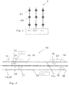
- the double strand 10 has two individual strands 11, 12.
- the single strand 11 consists of an (inner) copper wire 11k and an (outer) plastic sheath 11u. It has in the axial direction (arrow A) alternately a plurality of electrically insulated regions / sections 14, 16, 18 and in between a plurality of stripped sections / regions 13, 15. Each stripped portion 13, 15 has been obtained by cutting away the electrical insulation 11u, and accordingly has an oval shape in view.
- the strands 11, 12 are parallel to each other and are connected together at 23, since their respective sheath 11u, 12u are material fit. Due to the axial offset (English: offset) of the non-insulated sections 13, 17 and 15, 19, however, there is normally no electrical contact between the two individual strands 11, 12.
- the total strand / double strand 10 has two detection areas D1 and D2. In the first detection area D1, the stripped regions 13 and 17 are arranged, with a spacing in the axial direction (arrow A). In the second detection area D2, this is analogous (areas 15, 19).
- Fig. 1 is the axial length of the stripped regions 13, 15, 17, 19 each 1 cm and the electrically insulated sections each 20 cm.
- the stripped regions 13, 17 and 15, 19 are arranged axially offset by 2 cm in each case.
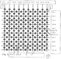
- FIG. 2 shows a plan view of a moisture detection device according to a first embodiment of the present invention.
- the device is integrated in a flat roof and runs parallel to a building ceiling in the thermal insulation of the roof.
- corresponding channels / slots are provided in the heat insulation, in which the lines / strands are laid.
- the device has a plurality of double strands 10.1 ... 10.10 and 20.1 ... 20.10.
- the double strands 10, 20 are arranged in a grid pattern.
- the double strands 10 run parallel to each other in the Y direction and are spaced in the X direction.
- the double strands 20 extend parallel to each other in the X direction (a normal coordinate system) at a distance in the Y direction.
- At nodal points K are two double strands 10, 20 with their isolated sections one above the other; an electrical connection does not exist at these nodes K.
- Each double strand 10,20 is analogous to the example to Fig. 1 constructed and has a plurality of detection areas, which are shown schematically by circles D.
- the detection areas are arranged at the same distance within the grid to each other.
- the detection areas are analogous as in Fig. 1 designed illustrated.
- the double strands 10, 20 are connected to a power source, not shown, and to an evaluation device. Electric power flows through the double strands 10, 20. When liquid occurs in the region of at least one detection point D, a corresponding electrical resistance can be measured by the evaluation device. Above all, the location at which the moisture occurs can also be determined via the evaluation device, as will be explained below by way of example.
- the flat roof has a surface of 10m by 10m.
- FIG. 3 shows a plan view of a moisture detection device 1 according to a second embodiment of the invention, which can be used in the field of insulation between rafters.
- three double strands 10.1, 10.2, 10.3 are arranged parallel and spaced apart by 20 cm.
- the double strands are essentially analog Fig.1 designed and form together with a corresponding data processing system (evaluation) a moisture detection device.
Landscapes
- Physics & Mathematics (AREA)
- General Physics & Mathematics (AREA)
- Engineering & Computer Science (AREA)
- Architecture (AREA)
- Civil Engineering (AREA)
- Structural Engineering (AREA)
- Investigating Or Analyzing Materials By The Use Of Electric Means (AREA)
Priority Applications (4)
| Application Number | Priority Date | Filing Date | Title |
|---|---|---|---|
| SI201530159T SI3176342T1 (en) | 2015-12-03 | 2015-12-03 | A procedure for the location of humidity detection devices in roofs of buildings, in particular flat roofs |
| DK15197752.7T DK3176342T3 (en) | 2015-12-03 | 2015-12-03 | Method of arranging a device for detecting moisture in roofs of buildings, especially flat roofs |
| PL15197752T PL3176342T3 (pl) | 2015-12-03 | 2015-12-03 | Sposób rozmieszczania urządzenia do wykrywania wilgoci w dachach budynków, a w szczególności w dachach płaskich |
| EP15197752.7A EP3176342B1 (de) | 2015-12-03 | 2015-12-03 | Verfahren zur verlegung einer feuchtigkeitsdetektionsvorrichtung in dächern von gebäuden, insbesondere flachdächer |
Applications Claiming Priority (1)
| Application Number | Priority Date | Filing Date | Title |
|---|---|---|---|
| EP15197752.7A EP3176342B1 (de) | 2015-12-03 | 2015-12-03 | Verfahren zur verlegung einer feuchtigkeitsdetektionsvorrichtung in dächern von gebäuden, insbesondere flachdächer |
Publications (2)
| Publication Number | Publication Date |
|---|---|
| EP3176342A1 EP3176342A1 (de) | 2017-06-07 |
| EP3176342B1 true EP3176342B1 (de) | 2017-12-13 |
Family
ID=54783423
Family Applications (1)
| Application Number | Title | Priority Date | Filing Date |
|---|---|---|---|
| EP15197752.7A Active EP3176342B1 (de) | 2015-12-03 | 2015-12-03 | Verfahren zur verlegung einer feuchtigkeitsdetektionsvorrichtung in dächern von gebäuden, insbesondere flachdächer |
Country Status (4)
| Country | Link |
|---|---|
| EP (1) | EP3176342B1 (pl) |
| DK (1) | DK3176342T3 (pl) |
| PL (1) | PL3176342T3 (pl) |
| SI (1) | SI3176342T1 (pl) |
Families Citing this family (1)
| Publication number | Priority date | Publication date | Assignee | Title |
|---|---|---|---|---|
| EP3608648A1 (de) * | 2018-08-10 | 2020-02-12 | Johann Trummer | Vorrichtung und verfahren zur erkennung eines lecks |
Family Cites Families (3)
| Publication number | Priority date | Publication date | Assignee | Title |
|---|---|---|---|---|
| DE3600374A1 (de) | 1986-01-09 | 1987-07-23 | Gerd Neumann | Vorrichtung zur frueherkennung und eingrenzung von wasserschaeden durch kondensatbildung und leckagen an einem flachdach |
| EP0325665A1 (de) * | 1988-01-26 | 1989-08-02 | Klaus-Peter Kolbatz | Ortung von in eine geschlossene Decke eingedrungener Flüssigkeit, insbesondere Wasser |
| WO2009023956A1 (en) * | 2007-08-17 | 2009-02-26 | Detec Systems Llc | A method and apparatus to detect and locate roof leaks |
-
2015
- 2015-12-03 EP EP15197752.7A patent/EP3176342B1/de active Active
- 2015-12-03 PL PL15197752T patent/PL3176342T3/pl unknown
- 2015-12-03 DK DK15197752.7T patent/DK3176342T3/en active
- 2015-12-03 SI SI201530159T patent/SI3176342T1/en unknown
Non-Patent Citations (1)
| Title |
|---|
| None * |
Also Published As
| Publication number | Publication date |
|---|---|
| EP3176342A1 (de) | 2017-06-07 |
| DK3176342T3 (en) | 2018-01-15 |
| PL3176342T3 (pl) | 2018-04-30 |
| SI3176342T1 (en) | 2018-02-28 |
Similar Documents
| Publication | Publication Date | Title |
|---|---|---|
| EP4073327B1 (de) | Erkennen und orten von feuchtigkeit unter dacheindeckungen | |
| EP1875189B1 (de) | Leckprüf- und Leckortungsanordnung zur Leckprüfung und Leckortung von Flachdächern oder dergleichen | |
| EP0510045B1 (de) | Abdichtungsfolie mit einer elektrischen messeinrichtung zur erfassung von lecks in der folie | |
| EP3176342A1 (de) | Verfahren zur verlegung einer feuchtigkeitsdetektionsvorrichtung in dächern von gebäuden, insbesondere flachdächer | |
| EP3933137B1 (de) | Matte zur erstellung eines leckageortungs-sensors, ein solcher sensor, ein überwachungsgerät, eine gebäudefläche und ein verfahren zur herstellung und verwendung eines solchen sensors | |
| EP4130700A2 (de) | Verfahren zum feststellen der anwesenheit von wasser | |
| EP1601235A2 (de) | Überwachungseinrichtung für flexible Heizelemente | |
| EP3635358B1 (de) | Vorrichtung zur leckortung und feuchteüberwachung | |
| DE20018040U1 (de) | Wetterfeste Bodenmatte mit elektrischer Beheizung | |
| WO2018095487A1 (de) | Modul zur passiven flächenüberwachung | |
| EP2869050B1 (de) | Detektionsvorrichtung für Flachdächer | |
| EP3771907B1 (de) | Verfahren zur bestimmung des feuchtegehalts von beton und estrich | |
| EP4187238B1 (de) | Anordnung und verfahren zur feuchtigkeitsmessung in bauwerken | |
| EP4180791A1 (de) | Sensoranordnung | |
| DE202006000073U1 (de) | Diebstahlsicherungsvorrichtung für eine Photovoltaikanlage | |
| EP3176341A1 (de) | Flachdach-einbauteil | |
| DE4440389A1 (de) | Kombinationssensor zur Erfassung atmosphärischer Größen insbesondere zur Diagnose von Vereisungs- und Windbelastung technischer Objekte | |
| AT10487U1 (de) | System zur lokalisation, abschottung und quantifizierung von feuchtigkeit in dachaufbauten | |
| DE68909607T2 (de) | Heizsystem für Bodenbeläge. | |
| EP4471224A1 (de) | Baubahn | |
| EP1615019A1 (de) | Anlage zur Feuchtigkeitsermittlung | |
| EP4471223A1 (de) | Baubahn | |
| EP4352317A1 (de) | Verfahren und vorrichtung zum detektieren und lokalisieren von feuchtigkeit auf feuchteführenden flächen und/oder in feuchteführenden schichten | |
| EP4575521A1 (de) | Verfahren zur erfassung einer windeigenschaft an einer freileitung | |
| EP0325665A1 (de) | Ortung von in eine geschlossene Decke eingedrungener Flüssigkeit, insbesondere Wasser |
Legal Events
| Date | Code | Title | Description |
|---|---|---|---|
| 17P | Request for examination filed |
Effective date: 20161202 |
|
| AK | Designated contracting states |
Kind code of ref document: A1 Designated state(s): AL AT BE BG CH CY CZ DE DK EE ES FI FR GB GR HR HU IE IS IT LI LT LU LV MC MK MT NL NO PL PT RO RS SE SI SK SM TR |
|
| AX | Request for extension of the european patent |
Extension state: BA ME |
|
| PUAI | Public reference made under article 153(3) epc to a published international application that has entered the european phase |
Free format text: ORIGINAL CODE: 0009012 |
|
| STAA | Information on the status of an ep patent application or granted ep patent |
Free format text: STATUS: REQUEST FOR EXAMINATION WAS MADE |
|
| GRAP | Despatch of communication of intention to grant a patent |
Free format text: ORIGINAL CODE: EPIDOSNIGR1 |
|
| STAA | Information on the status of an ep patent application or granted ep patent |
Free format text: STATUS: GRANT OF PATENT IS INTENDED |
|
| INTG | Intention to grant announced |
Effective date: 20170626 |
|
| GRAS | Grant fee paid |
Free format text: ORIGINAL CODE: EPIDOSNIGR3 |
|
| GRAA | (expected) grant |
Free format text: ORIGINAL CODE: 0009210 |
|
| STAA | Information on the status of an ep patent application or granted ep patent |
Free format text: STATUS: THE PATENT HAS BEEN GRANTED |
|
| REG | Reference to a national code |
Ref country code: GB Ref legal event code: FG4D Free format text: NOT ENGLISH |
|
| REG | Reference to a national code |
Ref country code: AT Ref legal event code: REF Ref document number: 954509 Country of ref document: AT Kind code of ref document: T Effective date: 20171215 Ref country code: CH Ref legal event code: EP |
|
| REG | Reference to a national code |
Ref country code: IE Ref legal event code: FG4D Free format text: LANGUAGE OF EP DOCUMENT: GERMAN |
|
| REG | Reference to a national code |
Ref country code: DK Ref legal event code: T3 Effective date: 20180109 |
|
| REG | Reference to a national code |
Ref country code: DE Ref legal event code: R096 Ref document number: 502015002570 Country of ref document: DE |
|
| REG | Reference to a national code |
Ref country code: SE Ref legal event code: TRGR |
|
| REG | Reference to a national code |
Ref country code: NL Ref legal event code: MP Effective date: 20171213 |
|
| PG25 | Lapsed in a contracting state [announced via postgrant information from national office to epo] |
Ref country code: FI Free format text: LAPSE BECAUSE OF FAILURE TO SUBMIT A TRANSLATION OF THE DESCRIPTION OR TO PAY THE FEE WITHIN THE PRESCRIBED TIME-LIMIT Effective date: 20171213 Ref country code: NO Free format text: LAPSE BECAUSE OF FAILURE TO SUBMIT A TRANSLATION OF THE DESCRIPTION OR TO PAY THE FEE WITHIN THE PRESCRIBED TIME-LIMIT Effective date: 20180313 |
|
| PG25 | Lapsed in a contracting state [announced via postgrant information from national office to epo] |
Ref country code: HR Free format text: LAPSE BECAUSE OF FAILURE TO SUBMIT A TRANSLATION OF THE DESCRIPTION OR TO PAY THE FEE WITHIN THE PRESCRIBED TIME-LIMIT Effective date: 20171213 Ref country code: RS Free format text: LAPSE BECAUSE OF FAILURE TO SUBMIT A TRANSLATION OF THE DESCRIPTION OR TO PAY THE FEE WITHIN THE PRESCRIBED TIME-LIMIT Effective date: 20171213 Ref country code: LV Free format text: LAPSE BECAUSE OF FAILURE TO SUBMIT A TRANSLATION OF THE DESCRIPTION OR TO PAY THE FEE WITHIN THE PRESCRIBED TIME-LIMIT Effective date: 20171213 Ref country code: GR Free format text: LAPSE BECAUSE OF FAILURE TO SUBMIT A TRANSLATION OF THE DESCRIPTION OR TO PAY THE FEE WITHIN THE PRESCRIBED TIME-LIMIT Effective date: 20180314 Ref country code: BG Free format text: LAPSE BECAUSE OF FAILURE TO SUBMIT A TRANSLATION OF THE DESCRIPTION OR TO PAY THE FEE WITHIN THE PRESCRIBED TIME-LIMIT Effective date: 20180313 |
|
| PG25 | Lapsed in a contracting state [announced via postgrant information from national office to epo] |
Ref country code: NL Free format text: LAPSE BECAUSE OF FAILURE TO SUBMIT A TRANSLATION OF THE DESCRIPTION OR TO PAY THE FEE WITHIN THE PRESCRIBED TIME-LIMIT Effective date: 20171213 |
|
| PG25 | Lapsed in a contracting state [announced via postgrant information from national office to epo] |
Ref country code: CZ Free format text: LAPSE BECAUSE OF FAILURE TO SUBMIT A TRANSLATION OF THE DESCRIPTION OR TO PAY THE FEE WITHIN THE PRESCRIBED TIME-LIMIT Effective date: 20171213 Ref country code: SK Free format text: LAPSE BECAUSE OF FAILURE TO SUBMIT A TRANSLATION OF THE DESCRIPTION OR TO PAY THE FEE WITHIN THE PRESCRIBED TIME-LIMIT Effective date: 20171213 Ref country code: EE Free format text: LAPSE BECAUSE OF FAILURE TO SUBMIT A TRANSLATION OF THE DESCRIPTION OR TO PAY THE FEE WITHIN THE PRESCRIBED TIME-LIMIT Effective date: 20171213 Ref country code: CY Free format text: LAPSE BECAUSE OF FAILURE TO SUBMIT A TRANSLATION OF THE DESCRIPTION OR TO PAY THE FEE WITHIN THE PRESCRIBED TIME-LIMIT Effective date: 20171213 Ref country code: ES Free format text: LAPSE BECAUSE OF FAILURE TO SUBMIT A TRANSLATION OF THE DESCRIPTION OR TO PAY THE FEE WITHIN THE PRESCRIBED TIME-LIMIT Effective date: 20171213 |
|
| PG25 | Lapsed in a contracting state [announced via postgrant information from national office to epo] |
Ref country code: IT Free format text: LAPSE BECAUSE OF FAILURE TO SUBMIT A TRANSLATION OF THE DESCRIPTION OR TO PAY THE FEE WITHIN THE PRESCRIBED TIME-LIMIT Effective date: 20171213 Ref country code: RO Free format text: LAPSE BECAUSE OF FAILURE TO SUBMIT A TRANSLATION OF THE DESCRIPTION OR TO PAY THE FEE WITHIN THE PRESCRIBED TIME-LIMIT Effective date: 20171213 Ref country code: IS Free format text: LAPSE BECAUSE OF FAILURE TO SUBMIT A TRANSLATION OF THE DESCRIPTION OR TO PAY THE FEE WITHIN THE PRESCRIBED TIME-LIMIT Effective date: 20180413 Ref country code: SM Free format text: LAPSE BECAUSE OF FAILURE TO SUBMIT A TRANSLATION OF THE DESCRIPTION OR TO PAY THE FEE WITHIN THE PRESCRIBED TIME-LIMIT Effective date: 20171213 |
|
| REG | Reference to a national code |
Ref country code: DE Ref legal event code: R097 Ref document number: 502015002570 Country of ref document: DE |
|
| PG25 | Lapsed in a contracting state [announced via postgrant information from national office to epo] |
Ref country code: MT Free format text: LAPSE BECAUSE OF FAILURE TO SUBMIT A TRANSLATION OF THE DESCRIPTION OR TO PAY THE FEE WITHIN THE PRESCRIBED TIME-LIMIT Effective date: 20171213 |
|
| PLBE | No opposition filed within time limit |
Free format text: ORIGINAL CODE: 0009261 |
|
| STAA | Information on the status of an ep patent application or granted ep patent |
Free format text: STATUS: NO OPPOSITION FILED WITHIN TIME LIMIT |
|
| 26N | No opposition filed |
Effective date: 20180914 |
|
| PG25 | Lapsed in a contracting state [announced via postgrant information from national office to epo] |
Ref country code: LU Free format text: LAPSE BECAUSE OF NON-PAYMENT OF DUE FEES Effective date: 20181203 Ref country code: MC Free format text: LAPSE BECAUSE OF FAILURE TO SUBMIT A TRANSLATION OF THE DESCRIPTION OR TO PAY THE FEE WITHIN THE PRESCRIBED TIME-LIMIT Effective date: 20171213 |
|
| REG | Reference to a national code |
Ref country code: IE Ref legal event code: MM4A |
|
| PG25 | Lapsed in a contracting state [announced via postgrant information from national office to epo] |
Ref country code: IE Free format text: LAPSE BECAUSE OF NON-PAYMENT OF DUE FEES Effective date: 20181203 |
|
| PG25 | Lapsed in a contracting state [announced via postgrant information from national office to epo] |
Ref country code: TR Free format text: LAPSE BECAUSE OF FAILURE TO SUBMIT A TRANSLATION OF THE DESCRIPTION OR TO PAY THE FEE WITHIN THE PRESCRIBED TIME-LIMIT Effective date: 20171213 |
|
| PG25 | Lapsed in a contracting state [announced via postgrant information from national office to epo] |
Ref country code: PT Free format text: LAPSE BECAUSE OF FAILURE TO SUBMIT A TRANSLATION OF THE DESCRIPTION OR TO PAY THE FEE WITHIN THE PRESCRIBED TIME-LIMIT Effective date: 20171213 |
|
| PG25 | Lapsed in a contracting state [announced via postgrant information from national office to epo] |
Ref country code: LT Free format text: LAPSE BECAUSE OF FAILURE TO SUBMIT A TRANSLATION OF THE DESCRIPTION OR TO PAY THE FEE WITHIN THE PRESCRIBED TIME-LIMIT Effective date: 20171213 Ref country code: HU Free format text: LAPSE BECAUSE OF FAILURE TO SUBMIT A TRANSLATION OF THE DESCRIPTION OR TO PAY THE FEE WITHIN THE PRESCRIBED TIME-LIMIT; INVALID AB INITIO Effective date: 20151203 Ref country code: MK Free format text: LAPSE BECAUSE OF NON-PAYMENT OF DUE FEES Effective date: 20171213 |
|
| PG25 | Lapsed in a contracting state [announced via postgrant information from national office to epo] |
Ref country code: AL Free format text: LAPSE BECAUSE OF FAILURE TO SUBMIT A TRANSLATION OF THE DESCRIPTION OR TO PAY THE FEE WITHIN THE PRESCRIBED TIME-LIMIT Effective date: 20171213 |
|
| REG | Reference to a national code |
Ref country code: CH Ref legal event code: U11 Free format text: ST27 STATUS EVENT CODE: U-0-0-U10-U11 (AS PROVIDED BY THE NATIONAL OFFICE) Effective date: 20260101 |
|
| PGFP | Annual fee paid to national office [announced via postgrant information from national office to epo] |
Ref country code: GB Payment date: 20251218 Year of fee payment: 11 |
|
| PGFP | Annual fee paid to national office [announced via postgrant information from national office to epo] |
Ref country code: AT Payment date: 20251215 Year of fee payment: 11 |
|
| PGFP | Annual fee paid to national office [announced via postgrant information from national office to epo] |
Ref country code: DK Payment date: 20251217 Year of fee payment: 11 |
|
| PGFP | Annual fee paid to national office [announced via postgrant information from national office to epo] |
Ref country code: FR Payment date: 20251217 Year of fee payment: 11 |
|
| PGFP | Annual fee paid to national office [announced via postgrant information from national office to epo] |
Ref country code: BE Payment date: 20251218 Year of fee payment: 11 |
|
| PGFP | Annual fee paid to national office [announced via postgrant information from national office to epo] |
Ref country code: SE Payment date: 20251217 Year of fee payment: 11 |
|
| PGFP | Annual fee paid to national office [announced via postgrant information from national office to epo] |
Ref country code: PL Payment date: 20251219 Year of fee payment: 11 |
|
| PGFP | Annual fee paid to national office [announced via postgrant information from national office to epo] |
Ref country code: SI Payment date: 20251219 Year of fee payment: 11 |
|
| PGFP | Annual fee paid to national office [announced via postgrant information from national office to epo] |
Ref country code: DE Payment date: 20251222 Year of fee payment: 11 |
|
| PGFP | Annual fee paid to national office [announced via postgrant information from national office to epo] |
Ref country code: CH Payment date: 20260101 Year of fee payment: 11 |