EP3176437B1 - Compresseur fermé et dispositif frigorifique - Google Patents
Compresseur fermé et dispositif frigorifique Download PDFInfo
- Publication number
- EP3176437B1 EP3176437B1 EP16831700.6A EP16831700A EP3176437B1 EP 3176437 B1 EP3176437 B1 EP 3176437B1 EP 16831700 A EP16831700 A EP 16831700A EP 3176437 B1 EP3176437 B1 EP 3176437B1
- Authority
- EP
- European Patent Office
- Prior art keywords
- stator
- closed compressor
- bearing
- fixed
- crankshaft
- Prior art date
- Legal status (The legal status is an assumption and is not a legal conclusion. Google has not performed a legal analysis and makes no representation as to the accuracy of the status listed.)
- Active
Links
Images


Classifications
-
- F—MECHANICAL ENGINEERING; LIGHTING; HEATING; WEAPONS; BLASTING
- F04—POSITIVE - DISPLACEMENT MACHINES FOR LIQUIDS; PUMPS FOR LIQUIDS OR ELASTIC FLUIDS
- F04B—POSITIVE-DISPLACEMENT MACHINES FOR LIQUIDS; PUMPS
- F04B35/00—Piston pumps specially adapted for elastic fluids and characterised by the driving means to their working members, or by combination with, or adaptation to, specific driving engines or motors, not otherwise provided for
- F04B35/04—Piston pumps specially adapted for elastic fluids and characterised by the driving means to their working members, or by combination with, or adaptation to, specific driving engines or motors, not otherwise provided for the means being electric
-
- F—MECHANICAL ENGINEERING; LIGHTING; HEATING; WEAPONS; BLASTING
- F04—POSITIVE - DISPLACEMENT MACHINES FOR LIQUIDS; PUMPS FOR LIQUIDS OR ELASTIC FLUIDS
- F04B—POSITIVE-DISPLACEMENT MACHINES FOR LIQUIDS; PUMPS
- F04B35/00—Piston pumps specially adapted for elastic fluids and characterised by the driving means to their working members, or by combination with, or adaptation to, specific driving engines or motors, not otherwise provided for
- F04B35/01—Piston pumps specially adapted for elastic fluids and characterised by the driving means to their working members, or by combination with, or adaptation to, specific driving engines or motors, not otherwise provided for the means being mechanical
-
- F—MECHANICAL ENGINEERING; LIGHTING; HEATING; WEAPONS; BLASTING
- F04—POSITIVE - DISPLACEMENT MACHINES FOR LIQUIDS; PUMPS FOR LIQUIDS OR ELASTIC FLUIDS
- F04B—POSITIVE-DISPLACEMENT MACHINES FOR LIQUIDS; PUMPS
- F04B39/00—Component parts, details, or accessories, of pumps or pumping systems specially adapted for elastic fluids, not otherwise provided for in, or of interest apart from, groups F04B25/00 - F04B37/00
- F04B39/0027—Pulsation and noise damping means
- F04B39/0044—Pulsation and noise damping means with vibration damping supports
-
- F—MECHANICAL ENGINEERING; LIGHTING; HEATING; WEAPONS; BLASTING
- F04—POSITIVE - DISPLACEMENT MACHINES FOR LIQUIDS; PUMPS FOR LIQUIDS OR ELASTIC FLUIDS
- F04B—POSITIVE-DISPLACEMENT MACHINES FOR LIQUIDS; PUMPS
- F04B39/00—Component parts, details, or accessories, of pumps or pumping systems specially adapted for elastic fluids, not otherwise provided for in, or of interest apart from, groups F04B25/00 - F04B37/00
- F04B39/02—Lubrication
- F04B39/0223—Lubrication characterised by the compressor type
- F04B39/023—Hermetic compressors
-
- F—MECHANICAL ENGINEERING; LIGHTING; HEATING; WEAPONS; BLASTING
- F04—POSITIVE - DISPLACEMENT MACHINES FOR LIQUIDS; PUMPS FOR LIQUIDS OR ELASTIC FLUIDS
- F04B—POSITIVE-DISPLACEMENT MACHINES FOR LIQUIDS; PUMPS
- F04B39/00—Component parts, details, or accessories, of pumps or pumping systems specially adapted for elastic fluids, not otherwise provided for in, or of interest apart from, groups F04B25/00 - F04B37/00
- F04B39/12—Casings; Cylinders; Cylinder heads; Fluid connections
- F04B39/122—Cylinder block
-
- F—MECHANICAL ENGINEERING; LIGHTING; HEATING; WEAPONS; BLASTING
- F04—POSITIVE - DISPLACEMENT MACHINES FOR LIQUIDS; PUMPS FOR LIQUIDS OR ELASTIC FLUIDS
- F04B—POSITIVE-DISPLACEMENT MACHINES FOR LIQUIDS; PUMPS
- F04B39/00—Component parts, details, or accessories, of pumps or pumping systems specially adapted for elastic fluids, not otherwise provided for in, or of interest apart from, groups F04B25/00 - F04B37/00
- F04B39/12—Casings; Cylinders; Cylinder heads; Fluid connections
- F04B39/127—Mounting of a cylinder block in a casing
-
- F—MECHANICAL ENGINEERING; LIGHTING; HEATING; WEAPONS; BLASTING
- F04—POSITIVE - DISPLACEMENT MACHINES FOR LIQUIDS; PUMPS FOR LIQUIDS OR ELASTIC FLUIDS
- F04B—POSITIVE-DISPLACEMENT MACHINES FOR LIQUIDS; PUMPS
- F04B41/00—Pumping installations or systems specially adapted for elastic fluids
- F04B41/02—Pumping installations or systems specially adapted for elastic fluids having reservoirs
-
- F—MECHANICAL ENGINEERING; LIGHTING; HEATING; WEAPONS; BLASTING
- F04—POSITIVE - DISPLACEMENT MACHINES FOR LIQUIDS; PUMPS FOR LIQUIDS OR ELASTIC FLUIDS
- F04B—POSITIVE-DISPLACEMENT MACHINES FOR LIQUIDS; PUMPS
- F04B53/00—Component parts, details or accessories not provided for in, or of interest apart from, groups F04B1/00 - F04B23/00 or F04B39/00 - F04B47/00
- F04B53/16—Casings; Cylinders; Cylinder liners or heads; Fluid connections
-
- F—MECHANICAL ENGINEERING; LIGHTING; HEATING; WEAPONS; BLASTING
- F04—POSITIVE - DISPLACEMENT MACHINES FOR LIQUIDS; PUMPS FOR LIQUIDS OR ELASTIC FLUIDS
- F04B—POSITIVE-DISPLACEMENT MACHINES FOR LIQUIDS; PUMPS
- F04B53/00—Component parts, details or accessories not provided for in, or of interest apart from, groups F04B1/00 - F04B23/00 or F04B39/00 - F04B47/00
- F04B53/22—Arrangements for enabling ready assembly or disassembly
-
- F—MECHANICAL ENGINEERING; LIGHTING; HEATING; WEAPONS; BLASTING
- F25—REFRIGERATION OR COOLING; COMBINED HEATING AND REFRIGERATION SYSTEMS; HEAT PUMP SYSTEMS; MANUFACTURE OR STORAGE OF ICE; LIQUEFACTION SOLIDIFICATION OF GASES
- F25B—REFRIGERATION MACHINES, PLANTS OR SYSTEMS; COMBINED HEATING AND REFRIGERATION SYSTEMS; HEAT PUMP SYSTEMS
- F25B1/00—Compression machines, plants or systems with non-reversible cycle
- F25B1/02—Compression machines, plants or systems with non-reversible cycle with compressor of reciprocating-piston type
-
- H—ELECTRICITY
- H02—GENERATION; CONVERSION OR DISTRIBUTION OF ELECTRIC POWER
- H02K—DYNAMO-ELECTRIC MACHINES
- H02K1/00—Details of the magnetic circuit
- H02K1/06—Details of the magnetic circuit characterised by the shape, form or construction
- H02K1/12—Stationary parts of the magnetic circuit
- H02K1/18—Means for mounting or fastening magnetic stationary parts on to, or to, the stator structures
- H02K1/187—Means for mounting or fastening magnetic stationary parts on to, or to, the stator structures to inner stators
-
- H—ELECTRICITY
- H02—GENERATION; CONVERSION OR DISTRIBUTION OF ELECTRIC POWER
- H02K—DYNAMO-ELECTRIC MACHINES
- H02K1/00—Details of the magnetic circuit
- H02K1/06—Details of the magnetic circuit characterised by the shape, form or construction
- H02K1/22—Rotating parts of the magnetic circuit
- H02K1/27—Rotor cores with permanent magnets
- H02K1/2786—Outer rotors
-
- H—ELECTRICITY
- H02—GENERATION; CONVERSION OR DISTRIBUTION OF ELECTRIC POWER
- H02K—DYNAMO-ELECTRIC MACHINES
- H02K11/00—Structural association of dynamo-electric machines with electric components or with devices for shielding, monitoring or protection
- H02K11/30—Structural association with control circuits or drive circuits
- H02K11/33—Drive circuits, e.g. power electronics
-
- H—ELECTRICITY
- H02—GENERATION; CONVERSION OR DISTRIBUTION OF ELECTRIC POWER
- H02K—DYNAMO-ELECTRIC MACHINES
- H02K21/00—Synchronous motors having permanent magnets; Synchronous generators having permanent magnets
- H02K21/12—Synchronous motors having permanent magnets; Synchronous generators having permanent magnets with stationary armatures and rotating magnets
- H02K21/22—Synchronous motors having permanent magnets; Synchronous generators having permanent magnets with stationary armatures and rotating magnets with magnets rotating around the armatures, e.g. flywheel magnetos
-
- H—ELECTRICITY
- H02—GENERATION; CONVERSION OR DISTRIBUTION OF ELECTRIC POWER
- H02K—DYNAMO-ELECTRIC MACHINES
- H02K7/00—Arrangements for handling mechanical energy structurally associated with dynamo-electric machines, e.g. structural association with mechanical driving motors or auxiliary dynamo-electric machines
- H02K7/08—Structural association with bearings
- H02K7/083—Structural association with bearings radially supporting the rotary shaft at both ends of the rotor
-
- H—ELECTRICITY
- H02—GENERATION; CONVERSION OR DISTRIBUTION OF ELECTRIC POWER
- H02K—DYNAMO-ELECTRIC MACHINES
- H02K7/00—Arrangements for handling mechanical energy structurally associated with dynamo-electric machines, e.g. structural association with mechanical driving motors or auxiliary dynamo-electric machines
- H02K7/14—Structural association with mechanical loads, e.g. with hand-held machine tools or fans
Definitions
- the present invention relates to a closed compressor using an outer rotor motor as an electric motor, and a refrigeration device equipped with the closed compressor.
- a type of closed compressor includes a closed compressor in which a rotor is fixed to a crankshaft on an upper side of a stator, an auxiliary bearing that pivotally supports the crankshaft is provided below an electric motor, and the stator is fixed to the auxiliary bearing (for example, see PTL 1).
- FIG. 3 illustrates a longitudinal-sectional view of the closed compressor of the related art disclosed in PTL 1.
- the closed compressor includes compressing mechanism 2 that is accommodated in an upper portion of closed vessel 1 and compresses refrigerant gas, and electric motor 3 provided below the compressing mechanism 2, in which compressing mechanism 2 has crankshaft 4 that transmits rotation of electric motor 3 to compressing mechanism 2.
- Crankshaft 4 described above has an upper portion that is pivotally supported by main bearing 6 provided in main frame 5 of compressing mechanism 2, and a lower portion that is pivotally supported by auxiliary bearing 7 fixed to a lower portion of closed vessel 1.
- Compressing mechanism 2 configures a scroll-type compressing mechanism and is fixed to closed vessel 1 with fixed scroll 8 press-fitted into closed vessel 1.
- Electric motor 3 is an outer-rotor type motor and is configured to include stator 9 and rotor 10 provided to have a predetermined clearance from outer circumferential surface 9a of stator 9.
- Stator 9 is fixed to closed vessel 1 by being fastened, with bolt 11, to auxiliary bearing 7 fixed to closed vessel 1.
- rotor 10 is fixed to crankshaft 4 via bowl-shaped rotor housing 10a on an upper portion of stator 9.
- PTL 2 describes a closed compressor according to the preamble of claim 1.
- the invention provides a closed compressor that is able to reduce an occurrence of twist of crankshaft without processing the component members with high accuracy, and that is able to narrow the clearance between the inner circumference of the rotor and the outer circumference of the stator, thereby achieving high efficiency and reliability at low costs.
- the closed compressor of the invention comprises: a closed vessel that accommodates an electric element and a compression element which is driven by the electric element, wherein the compression element includes: a crankshaft having a main shaft, an eccentric shaft, and an auxiliary shaft provided under the main shaft; a cylinder block having a cylinder bore penetrating the cylinder block, the cylinder bore having a circular cylinder shape; a piston that reciprocates in the cylinder bore; a conrod that connects the piston and the eccentric shaft; a main bearing that is formed in the cylinder block and that pivotally supports a load in a radial direction, which acts on the main shaft of the crankshaft, and an auxiliary bearing that pivotally supports a load in a radial direction, which acts on the auxiliary shaft of the crankshaft, wherein the electric element is an outer-rotor type motor having a rotor fixed to the crankshaft on a main shaft side and a stator disposed on an inner side of the rotor, wherein the stator is fixed to a stat
- the closed compressor in the invention has a configuration in which a stator is fixed to a stator fixing member, the stator fixing member is fixed to a member of a compression element, which has a main bearing, and an auxiliary bearing is configured to be a member separate from the stator fixing member and is fixed to a stator fixing member.
- FIG. 1 is a longitudinal-sectional view of a closed compressor according to a first exemplary embodiment of the invention.
- a closed compressor according to the exemplary embodiment has closed vessel 101 formed through drawing of an iron plate, and electric element 102 and compressor body 104 having, as a main body, compression element 103, which is driven by electric element 102, are disposed inside the closed vessel.
- Compressor body 104 is elastically supported by suspension spring 105.
- refrigerant gas 106 such as hydrocarbon-based R600a having a low global warming potential, for example, is sealed in closed vessel 101 in a state in which the refrigerant gas has a relatively low temperature at the same pressure as on a low-pressure side of a refrigeration device (not illustrated), and lubricant 107 for lubrication is sealed in a bottom portion in closed vessel 101.
- closed vessel 101 is provided with suction pipe 108 having one end that communicates with a space inside closed vessel 101 and the other end that is connected to the refrigeration device (not illustrated), and a discharge pipe (not illustrated) that guides, to the refrigeration device (not illustrated), refrigerant gas 106 compressed in compression element 103.
- Compression element 103 is configured to include crankshaft 110, cylinder block 111, piston 112, conrod 113, or the like.
- Crankshaft 110 has eccentric shaft 114, main shaft 115, and auxiliary shaft 116 under main shaft 115.
- Cylinder block 111 is integrally provided with cylinder bore 118 that forms compression chamber 117, and is also provided with main bearing 119 that pivotally supports main shaft 115 such that the main shaft freely rotates, and thrust ball bearing 121 that supports a load of crankshaft 110 in a vertical direction on thrust surface 120.
- Piston 112 reciprocates in cylinder bore 118, and a piston pin (not illustrated) is disposed to have an axial core that is parallel to an axial core of eccentric shaft 114.
- Conrod 113 has large end hole 124 and a small end hole (not illustrated), eccentric shaft 114 is fitted into large end hole 124, and the piston pin is fitted into the small end hole. In this manner, eccentric shaft 114 is connected to piston 112.
- valve plate 126 provided with a suction hole (not illustrated) and a discharge hole (not illustrated), a suction valve (not illustrated) that opens and closes the suction hole (not illustrated), and cylinder head 127 that blocks valve plate 126 are fixed by being jointly fastened by a head bolt (not illustrated) in an end plane of an opening of cylinder bore 118 on a side opposite to crankshaft 110.
- Cylinder head 127 is provided in a discharge space to which refrigerant gas 106 is discharged, and the discharge space directly communicates with a discharge pipe (not illustrated) via discharge piping (not illustrated).
- Electric element 102 is an outer-rotor type motor configured to include rotor 128 fixed to the main shaft 115 side of crankshaft 110 via rotor housing 128b, and stator 129 disposed on an inner side of rotor 128.
- Stator 129 is fixed to stator fixing member 130 with screw 131, and stator fixing member 130 is fixed to leg 132 extending downward from cylinder block 111.
- Auxiliary bearing 133 which pivotally supports auxiliary shaft 116 of crankshaft 110 such that the auxiliary shaft freely rotates, is fixed to stator fixing member 130.
- the closed compressor configures a refrigeration cycle, with suction pipe 108 and the discharge pipe (not illustrated) connected to a refrigeration device (not illustrated) having a known configuration.
- crankshaft 110 rotates in response to the rotation thereof, and piston 112 reciprocates in cylinder bore 118 via conrod 113 that is attached to eccentric shaft 114 such that the conrod freely rotates.
- rotor 128 as a rotating member is positioned above a lower end of stator 129, and is far from an oil level of lubricant 107, it is possible to prevent lubricant 107 from being stirred such that it is possible to reduce a stirring loss.
- Rotor 128 is fixed through shrink-fitting to main shaft 115 side of crankshaft 110, and stator 129 is fixed to stator fixing member 130 with screw 131.
- Stator 129 fixed to stator fixing member 130 in a manner described above is installed in the inner side of rotor 128. After positioning is performed with a jig such that an even clearance is formed between inner circumference 128a of rotor 128 and outer circumference 129a of stator 129, stator fixing member 130 is fixed to leg 132 extending downward from cylinder block 111. In this manner, it is possible to obtain coaxiality between inner circumference 128a of rotor 128 and outer circumference 129a of stator 129 with accuracy. Therefore, it is possible to narrow the clearance between inner circumference 128a of rotor 128 and outer circumference 129a of stator 129 such that it is possible to achieve high efficiency of the motor.
- Auxiliary bearing 133 is temporarily joined to stator fixing member 130, crankshaft 110 is rotated and the rotational torque is measured while the position of auxiliary bearing 133 is changed.
- crankshaft 110 is rotated and the rotational torque is measured while the position of auxiliary bearing 133 is changed.
- auxiliary bearing 133 is fixed to stator fixing member 130 at a position at which the minimum rotational torque is produced. In this manner, since it is possible to perform the assembling in a state in which crankshaft 110 has the minimum twist, it is possible to reduce a sliding loss such that it is possible to enhance reliability.
- auxiliary bearing 133 is a spherical bearing, it is possible to reduce an occurrence of the twist of crankshaft 110 without positioning auxiliary bearing 133 unlike the above description such that it is possible to improve productivity.
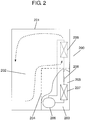
- FIG. 2 illustrates a refrigeration device according to a second exemplary embodiment of the invention, and a configuration in which the closed compressor described in the first exemplary embodiment is equipped on a refrigerant circuit is adopted.
- a basic configuration of the refrigeration device is schematically described.
- refrigeration device 200 includes main body 201 configured to include a box member that has one open side and has thermal insulation properties, and a door body which opens and closes the opening, partition wall 204 that partitions the inside of main body 201 into storage space 202 of goods and mechanical chamber 203, and refrigerant circuit 205 that cools the inside of storage space 202.
- Refrigerant circuit 205 is configured of ring-shaped piping connection with closed compressor 206, radiator 207, decompressor 208, and heat sink 209.
- Closed compressor 206 is the closed compressor described in the first exemplary embodiment.
- heat sink 209 is disposed in storage space 202 provided with a blower (not illustrated). As illustrated with a dashed-line arrow, cooling heat of heat sink 209 is stirred by the blower so as to circulate inside storage space 202.
- the refrigeration device described above is equipped with closed compressor 206 described in the first exemplary embodiment.
- closed compressor 206 described in the first exemplary embodiment.
- a closed vessel accommodates the electric element and the compression element that is driven by the electric element.
- the compression element includes the crankshaft that is configured to have the main shaft, the eccentric shaft, and the auxiliary shaft provided under the main shaft, the cylinder block having the cylinder bore provided to have a penetrating circular cylinder shape, the piston that reciprocates in the cylinder bore, and the conrod that connects the piston and the eccentric shaft.
- the compression element includes the main bearing that is formed in the cylinder block and that pivotally supports a load in a radial direction, which acts on the main shaft of the crankshaft, and the auxiliary bearing that pivotally supports a load in a radial direction, which acts on the auxiliary shaft of the crankshaft.
- the electric element is the outer-rotor type motor that is configured to have a rotor fixed to the crankshaft on the main shaft side and a stator disposed on an inner side of the rotor, in which the stator is fixed to the stator fixing member disposed on the auxiliary shaft side, the stator fixing member is fixed to the compression element, and the auxiliary bearing is fixed to the stator fixing member.
- the stator may be configured to be fixed to the stator fixing member through screwing.
- a spherical bearing may be used as the auxiliary bearing.
- the electric element may be configured to be driven at a plurality of operation frequencies using the inverter.
- the refrigeration device may include: the closed compressor described above; and the refrigerant circuit that connects the radiator, the decompressor, and the heat sink with piping in the ring shape.
- the invention is not limited to an electric refrigerator or an air conditioner for a household use, and can be widely applied to a refrigeration device in an industrial showcase, a vending machine, or the like.
Landscapes
- Engineering & Computer Science (AREA)
- Mechanical Engineering (AREA)
- General Engineering & Computer Science (AREA)
- Power Engineering (AREA)
- Physics & Mathematics (AREA)
- Thermal Sciences (AREA)
- Microelectronics & Electronic Packaging (AREA)
- Compressor (AREA)
Claims (9)
- Compresseur fermé comprenant:un récipient fermé (101) qui loge un élément électrique (102) et un élément de compression (103) qui est entraîné par l'élément électrique (102),dans lequel l'élément de compression (103) inclut:un vilebrequin (110) ayant un arbre principal (115), un arbre excentrique (114), et un arbre auxiliaire (116) disposé sous l'arbre principal;un bloc-cylindres (111) ayant un alésage de cylindre (118) pénétrant dans le bloc-cylindres (111), l'alésage de cylindre (118) ayant une forme de cylindre circulaire;un piston (112) qui effectue un mouvement de va-et-vient dans l'alésage de cylindre (118);une bielle (113) qui relie le piston (112) et l'arbre excentrique (114);un palier principal (119) qui est formé dans le bloc-cylindres (111) et supporte de manière pivotante une charge dans une direction radiale, qui agit sur l'arbre principal (115) du vilebrequin (110), etun palier auxiliaire (133) qui supporte de manière pivotante une charge dans une direction radiale, qui agit sur l'arbre auxiliaire (116) du vilebrequin (110),dans lequel l'élément électrique (102) est un moteur de type à rotor externe ayant un rotor (128) fixé au vilebrequin (110) sur un côté arbre principal et un stator (129) disposé sur un côté interne du rotor (128),dans lequel le stator (129) est fixé à un élément de fixation de stator (130) disposé sur un côté arbre auxiliaire,dans lequel l'élément de fixation de stator (130) est fixé à l'élément de compression (103),caractérisé en ce quele palier auxiliaire (133) est un élément séparé de l'élément de fixation de stator (130) et est fixé à l'élément de fixation de stator (130) dans un état dans lequel le palier auxiliaire (133) est coaxial au palier principal (119).
- Compresseur fermé selon la revendication 1,
dans lequel le stator (129) est fixé à l'élément de fixation de stator (130) par une vis (131). - Compresseur fermé selon la revendication 1,
dans lequel le palier auxiliaire (133) est un palier sphérique. - Compresseur fermé selon la revendication 2,
dans lequel le palier auxiliaire (133) est un palier sphérique. - Compresseur fermé selon la revendication 1,
dans lequel l'élément électrique (102) est configuré pour être entraîné à une pluralité de fréquences de fonctionnement à l'aide d'un onduleur. - Compresseur fermé selon la revendication 2,
dans lequel l'élément électrique (102) est configuré pour être entraîné à une pluralité de fréquences de fonctionnement à l'aide d'un onduleur. - Compresseur fermé selon la revendication 3,
dans lequel l'élément électrique (102) est configuré pour être entraîné à une pluralité de fréquences de fonctionnement à l'aide d'un onduleur. - Compresseur fermé selon la revendication 4,
dans lequel l'élément électrique (102) est configuré pour être entraîné à une pluralité de fréquences de fonctionnement à l'aide d'un onduleur. - Dispositif de réfrigération comprenant:le compresseur fermé selon l'une quelconque des revendications 1 à 8; etun circuit de réfrigérant qui relie un radiateur, un décompresseur et un dissipateur thermique avec une tuyauterie en forme d'anneau.
Applications Claiming Priority (2)
| Application Number | Priority Date | Filing Date | Title |
|---|---|---|---|
| JP2015165789 | 2015-08-25 | ||
| PCT/JP2016/003598 WO2017033413A1 (fr) | 2015-08-25 | 2016-08-04 | Compresseur fermé et dispositif frigorifique |
Publications (3)
| Publication Number | Publication Date |
|---|---|
| EP3176437A1 EP3176437A1 (fr) | 2017-06-07 |
| EP3176437A4 EP3176437A4 (fr) | 2017-11-22 |
| EP3176437B1 true EP3176437B1 (fr) | 2019-01-30 |
Family
ID=58099727
Family Applications (1)
| Application Number | Title | Priority Date | Filing Date |
|---|---|---|---|
| EP16831700.6A Active EP3176437B1 (fr) | 2015-08-25 | 2016-08-04 | Compresseur fermé et dispositif frigorifique |
Country Status (5)
| Country | Link |
|---|---|
| US (1) | US10830222B2 (fr) |
| EP (1) | EP3176437B1 (fr) |
| JP (1) | JP6214821B2 (fr) |
| CN (1) | CN106662092B (fr) |
| WO (1) | WO2017033413A1 (fr) |
Families Citing this family (7)
| Publication number | Priority date | Publication date | Assignee | Title |
|---|---|---|---|---|
| WO2018126208A1 (fr) * | 2016-12-30 | 2018-07-05 | Aspen Compressor, Llc | Compresseurs rotatifs assistés par volant |
| WO2019155998A1 (fr) * | 2018-02-08 | 2019-08-15 | パナソニック アプライアンシズ リフリジレーション デヴァイシズ シンガポール | Compresseur et dispositif de réfrigération l'utilisant |
| WO2020085427A1 (fr) * | 2018-10-26 | 2020-04-30 | パナソニック アプライアンシズ リフリジレーション デヴァイシズ シンガポール | Compresseur hermétique et dispositif de réfrigération |
| KR102319349B1 (ko) * | 2020-01-09 | 2021-10-28 | 엘지전자 주식회사 | 모터 조립체 및 이를 포함하는 왕복동식 압축기 |
| CN114251245B (zh) * | 2021-12-22 | 2024-09-24 | 黄石东贝压缩机有限公司 | 一种活塞式压缩机结构 |
| CN117212099B (zh) * | 2022-06-02 | 2026-03-24 | 安徽美芝制冷设备有限公司 | 压缩机及制冷设备 |
| US20240426286A1 (en) * | 2023-06-22 | 2024-12-26 | Samsung Electronics Co., Ltd. | Reciprocating compressor using outer rotor motor |
Family Cites Families (22)
| Publication number | Priority date | Publication date | Assignee | Title |
|---|---|---|---|---|
| US2349845A (en) * | 1942-02-05 | 1944-05-30 | Westinghouse Electric & Mfg Co | Refrigerating apparatus |
| KR950007515B1 (ko) * | 1990-01-08 | 1995-07-11 | 가부시기가이샤 히다찌 세아사꾸쇼 | 스크롤 압축기 |
| KR960015822B1 (ko) * | 1991-10-03 | 1996-11-21 | 가부시끼가이샤 히다찌세이사꾸쇼 | 밀폐형 전동압축기 |
| JP3640815B2 (ja) * | 1998-11-05 | 2005-04-20 | 株式会社東芝 | ファン装置及び冷蔵庫 |
| JP4331852B2 (ja) * | 2000-03-16 | 2009-09-16 | 国産電機株式会社 | 電動圧縮機及び電動圧縮機の電動機組立方法 |
| JP3600781B2 (ja) * | 2000-06-06 | 2004-12-15 | 株式会社日立製作所 | 密閉形電動圧縮機用保護装置、並びにこれを用いた密閉形電動圧縮機及び冷却システム |
| JP2003166467A (ja) * | 2001-11-29 | 2003-06-13 | Toyota Industries Corp | 車両用回転機械 |
| JP4595408B2 (ja) * | 2004-07-08 | 2010-12-08 | パナソニック株式会社 | 圧縮機 |
| JP2006170005A (ja) | 2004-12-14 | 2006-06-29 | Toshiba Kyaria Kk | 密閉型圧縮機及びこれを用いた冷凍サイクル装置 |
| JP2009138521A (ja) * | 2007-12-03 | 2009-06-25 | Sanden Corp | 電動圧縮機の制御方法 |
| JP4510098B2 (ja) * | 2008-01-07 | 2010-07-21 | 日立アプライアンス株式会社 | スクロール圧縮機 |
| BRPI0801482A2 (pt) * | 2008-05-13 | 2010-01-12 | Whirlpool Sa | motor, compressor de gás e elemento de agitação |
| KR101720536B1 (ko) * | 2010-01-08 | 2017-03-28 | 삼성전자주식회사 | 밀폐형 압축기 |
| FR2961268B1 (fr) | 2010-06-15 | 2012-08-03 | Valeo Thermal Sys Japan Co | Compresseur electrique a arbre court |
| JP5503494B2 (ja) * | 2010-10-21 | 2014-05-28 | 日立アプライアンス株式会社 | 密閉型圧縮機およびこれを用いた冷蔵庫 |
| JP2013024064A (ja) | 2011-07-19 | 2013-02-04 | Hitachi Appliances Inc | 密閉型圧縮機 |
| JP5652359B2 (ja) * | 2011-09-12 | 2015-01-14 | 株式会社豊田自動織機 | 電動圧縮機 |
| JP6010762B2 (ja) * | 2011-12-27 | 2016-10-19 | パナソニックIpマネジメント株式会社 | 密閉型圧縮機およびそれを備える冷蔵庫 |
| JP2013160291A (ja) * | 2012-02-03 | 2013-08-19 | Nsk Ltd | スラスト玉軸受 |
| US9995291B2 (en) | 2012-07-25 | 2018-06-12 | Panasonic Appliances Refrigeration Devices Singapore | Sealed compressor and refrigeration unit including sealed compressor |
| CN203962397U (zh) * | 2014-06-17 | 2014-11-26 | 广东美芝制冷设备有限公司 | 制冷循环系统及其外转子旋转式压缩机 |
| CN203962324U (zh) * | 2014-07-01 | 2014-11-26 | 安徽美芝制冷设备有限公司 | 具有外转子式电机的压缩机 |
-
2016
- 2016-08-04 US US15/503,306 patent/US10830222B2/en active Active
- 2016-08-04 CN CN201680002275.6A patent/CN106662092B/zh active Active
- 2016-08-04 JP JP2017512064A patent/JP6214821B2/ja active Active
- 2016-08-04 EP EP16831700.6A patent/EP3176437B1/fr active Active
- 2016-08-04 WO PCT/JP2016/003598 patent/WO2017033413A1/fr not_active Ceased
Non-Patent Citations (1)
| Title |
|---|
| None * |
Also Published As
| Publication number | Publication date |
|---|---|
| JP6214821B2 (ja) | 2017-10-18 |
| EP3176437A4 (fr) | 2017-11-22 |
| JPWO2017033413A1 (ja) | 2017-08-24 |
| WO2017033413A1 (fr) | 2017-03-02 |
| US20180216609A1 (en) | 2018-08-02 |
| CN106662092A (zh) | 2017-05-10 |
| CN106662092B (zh) | 2018-03-09 |
| US10830222B2 (en) | 2020-11-10 |
| EP3176437A1 (fr) | 2017-06-07 |
Similar Documents
| Publication | Publication Date | Title |
|---|---|---|
| EP3176437B1 (fr) | Compresseur fermé et dispositif frigorifique | |
| US10491088B2 (en) | Permanent magnet motor with a rotor having press fitted rivets and press fitted shaft and pin holes and a method for manufacturing the rotor | |
| JP6585588B2 (ja) | 密閉型圧縮機および冷凍装置 | |
| EP3168474A1 (fr) | Compresseur hermétique, et dispositif de réfrigération mettant en oeuvre celui-ci | |
| US20170306941A1 (en) | Hermetic compressor and refrigeration device | |
| JP6648342B2 (ja) | 密閉型冷媒圧縮機および冷凍装置 | |
| JP2020112032A (ja) | 密閉型圧縮機およびそれを用いた冷凍装置 | |
| KR102320908B1 (ko) | 압축기 및 냉동 사이클 장치 | |
| JP2017145787A (ja) | 密閉型圧縮機およびそれを用いた冷凍装置 | |
| KR101300961B1 (ko) | 로터리 압축기 | |
| US7993114B2 (en) | Electric compressor | |
| JP2009197644A (ja) | 密閉型圧縮機 | |
| KR101992586B1 (ko) | 압축기 및 냉동 사이클 장치 | |
| JP2019138269A (ja) | 密閉型圧縮機および冷凍装置 | |
| US20210102539A1 (en) | Compressor | |
| JP6348298B2 (ja) | 密閉型圧縮機および冷凍装置 | |
| EP2212557A1 (fr) | Compresseur | |
| WO2015078532A1 (fr) | Compresseur alternatif de taille réduite et de forme améliorée à utiliser dans un appareil de réfrigération | |
| JP2020094558A (ja) | 密閉型圧縮機及び冷凍装置 | |
| JP2010242565A (ja) | 密閉形圧縮機及びこれを備えた冷蔵庫 | |
| JP2018025142A (ja) | 密閉型圧縮機およびそれを用いた冷凍装置 | |
| JP2019138267A (ja) | 冷媒圧縮機およびそれを用いた冷凍装置 | |
| JP2007198335A (ja) | 電動圧縮機 | |
| JP2013181516A (ja) | スクロール圧縮機 |
Legal Events
| Date | Code | Title | Description |
|---|---|---|---|
| STAA | Information on the status of an ep patent application or granted ep patent |
Free format text: STATUS: UNKNOWN |
|
| STAA | Information on the status of an ep patent application or granted ep patent |
Free format text: STATUS: THE INTERNATIONAL PUBLICATION HAS BEEN MADE |
|
| 17P | Request for examination filed |
Effective date: 20170208 |
|
| AK | Designated contracting states |
Kind code of ref document: A1 Designated state(s): AL AT BE BG CH CY CZ DE DK EE ES FI FR GB GR HR HU IE IS IT LI LT LU LV MC MK MT NL NO PL PT RO RS SE SI SK SM TR |
|
| AX | Request for extension of the european patent |
Extension state: BA ME |
|
| PUAI | Public reference made under article 153(3) epc to a published international application that has entered the european phase |
Free format text: ORIGINAL CODE: 0009012 |
|
| STAA | Information on the status of an ep patent application or granted ep patent |
Free format text: STATUS: REQUEST FOR EXAMINATION WAS MADE |
|
| A4 | Supplementary search report drawn up and despatched |
Effective date: 20171020 |
|
| RIC1 | Information provided on ipc code assigned before grant |
Ipc: F04B 39/00 20060101AFI20171016BHEP Ipc: F25B 1/02 20060101ALI20171016BHEP Ipc: F25B 31/02 20060101ALI20171016BHEP Ipc: F04B 39/02 20060101ALI20171016BHEP Ipc: H02K 1/27 20060101ALI20171016BHEP Ipc: H02K 21/22 20060101ALI20171016BHEP Ipc: F04B 35/04 20060101ALI20171016BHEP |
|
| RAP1 | Party data changed (applicant data changed or rights of an application transferred) |
Owner name: PANASONIC CORPORATION |
|
| GRAP | Despatch of communication of intention to grant a patent |
Free format text: ORIGINAL CODE: EPIDOSNIGR1 |
|
| STAA | Information on the status of an ep patent application or granted ep patent |
Free format text: STATUS: GRANT OF PATENT IS INTENDED |
|
| RIC1 | Information provided on ipc code assigned before grant |
Ipc: F04B 35/04 20060101ALI20180710BHEP Ipc: H02K 7/14 20060101ALI20180710BHEP Ipc: F25B 31/02 20060101ALI20180710BHEP Ipc: H02K 7/08 20060101ALI20180710BHEP Ipc: F25B 1/02 20060101ALI20180710BHEP Ipc: H02K 21/22 20060101ALI20180710BHEP Ipc: F04B 39/00 20060101AFI20180710BHEP Ipc: F04B 39/02 20060101ALI20180710BHEP |
|
| INTG | Intention to grant announced |
Effective date: 20180801 |
|
| DAV | Request for validation of the european patent (deleted) | ||
| DAX | Request for extension of the european patent (deleted) | ||
| GRAS | Grant fee paid |
Free format text: ORIGINAL CODE: EPIDOSNIGR3 |
|
| GRAA | (expected) grant |
Free format text: ORIGINAL CODE: 0009210 |
|
| STAA | Information on the status of an ep patent application or granted ep patent |
Free format text: STATUS: THE PATENT HAS BEEN GRANTED |
|
| AK | Designated contracting states |
Kind code of ref document: B1 Designated state(s): AL AT BE BG CH CY CZ DE DK EE ES FI FR GB GR HR HU IE IS IT LI LT LU LV MC MK MT NL NO PL PT RO RS SE SI SK SM TR |
|
| REG | Reference to a national code |
Ref country code: GB Ref legal event code: FG4D |
|
| REG | Reference to a national code |
Ref country code: CH Ref legal event code: EP |
|
| REG | Reference to a national code |
Ref country code: AT Ref legal event code: REF Ref document number: 1093495 Country of ref document: AT Kind code of ref document: T Effective date: 20190215 |
|
| REG | Reference to a national code |
Ref country code: IE Ref legal event code: FG4D |
|
| REG | Reference to a national code |
Ref country code: DE Ref legal event code: R096 Ref document number: 602016009730 Country of ref document: DE |
|
| REG | Reference to a national code |
Ref country code: LT Ref legal event code: MG4D |
|
| REG | Reference to a national code |
Ref country code: NL Ref legal event code: MP Effective date: 20190130 |
|
| RAP2 | Party data changed (patent owner data changed or rights of a patent transferred) |
Owner name: PANASONIC APPLIANCES REFRIGERATION DEVICES SINGAPO |
|
| PG25 | Lapsed in a contracting state [announced via postgrant information from national office to epo] |
Ref country code: ES Free format text: LAPSE BECAUSE OF FAILURE TO SUBMIT A TRANSLATION OF THE DESCRIPTION OR TO PAY THE FEE WITHIN THE PRESCRIBED TIME-LIMIT Effective date: 20190130 Ref country code: PL Free format text: LAPSE BECAUSE OF FAILURE TO SUBMIT A TRANSLATION OF THE DESCRIPTION OR TO PAY THE FEE WITHIN THE PRESCRIBED TIME-LIMIT Effective date: 20190130 Ref country code: PT Free format text: LAPSE BECAUSE OF FAILURE TO SUBMIT A TRANSLATION OF THE DESCRIPTION OR TO PAY THE FEE WITHIN THE PRESCRIBED TIME-LIMIT Effective date: 20190530 Ref country code: NO Free format text: LAPSE BECAUSE OF FAILURE TO SUBMIT A TRANSLATION OF THE DESCRIPTION OR TO PAY THE FEE WITHIN THE PRESCRIBED TIME-LIMIT Effective date: 20190430 Ref country code: SE Free format text: LAPSE BECAUSE OF FAILURE TO SUBMIT A TRANSLATION OF THE DESCRIPTION OR TO PAY THE FEE WITHIN THE PRESCRIBED TIME-LIMIT Effective date: 20190130 Ref country code: FI Free format text: LAPSE BECAUSE OF FAILURE TO SUBMIT A TRANSLATION OF THE DESCRIPTION OR TO PAY THE FEE WITHIN THE PRESCRIBED TIME-LIMIT Effective date: 20190130 Ref country code: LT Free format text: LAPSE BECAUSE OF FAILURE TO SUBMIT A TRANSLATION OF THE DESCRIPTION OR TO PAY THE FEE WITHIN THE PRESCRIBED TIME-LIMIT Effective date: 20190130 Ref country code: NL Free format text: LAPSE BECAUSE OF FAILURE TO SUBMIT A TRANSLATION OF THE DESCRIPTION OR TO PAY THE FEE WITHIN THE PRESCRIBED TIME-LIMIT Effective date: 20190130 |
|
| REG | Reference to a national code |
Ref country code: AT Ref legal event code: MK05 Ref document number: 1093495 Country of ref document: AT Kind code of ref document: T Effective date: 20190130 |
|
| PG25 | Lapsed in a contracting state [announced via postgrant information from national office to epo] |
Ref country code: IS Free format text: LAPSE BECAUSE OF FAILURE TO SUBMIT A TRANSLATION OF THE DESCRIPTION OR TO PAY THE FEE WITHIN THE PRESCRIBED TIME-LIMIT Effective date: 20190530 Ref country code: BG Free format text: LAPSE BECAUSE OF FAILURE TO SUBMIT A TRANSLATION OF THE DESCRIPTION OR TO PAY THE FEE WITHIN THE PRESCRIBED TIME-LIMIT Effective date: 20190430 Ref country code: LV Free format text: LAPSE BECAUSE OF FAILURE TO SUBMIT A TRANSLATION OF THE DESCRIPTION OR TO PAY THE FEE WITHIN THE PRESCRIBED TIME-LIMIT Effective date: 20190130 Ref country code: RS Free format text: LAPSE BECAUSE OF FAILURE TO SUBMIT A TRANSLATION OF THE DESCRIPTION OR TO PAY THE FEE WITHIN THE PRESCRIBED TIME-LIMIT Effective date: 20190130 Ref country code: GR Free format text: LAPSE BECAUSE OF FAILURE TO SUBMIT A TRANSLATION OF THE DESCRIPTION OR TO PAY THE FEE WITHIN THE PRESCRIBED TIME-LIMIT Effective date: 20190501 Ref country code: HR Free format text: LAPSE BECAUSE OF FAILURE TO SUBMIT A TRANSLATION OF THE DESCRIPTION OR TO PAY THE FEE WITHIN THE PRESCRIBED TIME-LIMIT Effective date: 20190130 |
|
| PG25 | Lapsed in a contracting state [announced via postgrant information from national office to epo] |
Ref country code: CZ Free format text: LAPSE BECAUSE OF FAILURE TO SUBMIT A TRANSLATION OF THE DESCRIPTION OR TO PAY THE FEE WITHIN THE PRESCRIBED TIME-LIMIT Effective date: 20190130 Ref country code: SK Free format text: LAPSE BECAUSE OF FAILURE TO SUBMIT A TRANSLATION OF THE DESCRIPTION OR TO PAY THE FEE WITHIN THE PRESCRIBED TIME-LIMIT Effective date: 20190130 Ref country code: AL Free format text: LAPSE BECAUSE OF FAILURE TO SUBMIT A TRANSLATION OF THE DESCRIPTION OR TO PAY THE FEE WITHIN THE PRESCRIBED TIME-LIMIT Effective date: 20190130 Ref country code: RO Free format text: LAPSE BECAUSE OF FAILURE TO SUBMIT A TRANSLATION OF THE DESCRIPTION OR TO PAY THE FEE WITHIN THE PRESCRIBED TIME-LIMIT Effective date: 20190130 Ref country code: IT Free format text: LAPSE BECAUSE OF FAILURE TO SUBMIT A TRANSLATION OF THE DESCRIPTION OR TO PAY THE FEE WITHIN THE PRESCRIBED TIME-LIMIT Effective date: 20190130 Ref country code: EE Free format text: LAPSE BECAUSE OF FAILURE TO SUBMIT A TRANSLATION OF THE DESCRIPTION OR TO PAY THE FEE WITHIN THE PRESCRIBED TIME-LIMIT Effective date: 20190130 Ref country code: DK Free format text: LAPSE BECAUSE OF FAILURE TO SUBMIT A TRANSLATION OF THE DESCRIPTION OR TO PAY THE FEE WITHIN THE PRESCRIBED TIME-LIMIT Effective date: 20190130 |
|
| REG | Reference to a national code |
Ref country code: DE Ref legal event code: R097 Ref document number: 602016009730 Country of ref document: DE |
|
| PG25 | Lapsed in a contracting state [announced via postgrant information from national office to epo] |
Ref country code: SM Free format text: LAPSE BECAUSE OF FAILURE TO SUBMIT A TRANSLATION OF THE DESCRIPTION OR TO PAY THE FEE WITHIN THE PRESCRIBED TIME-LIMIT Effective date: 20190130 |
|
| PLBE | No opposition filed within time limit |
Free format text: ORIGINAL CODE: 0009261 |
|
| STAA | Information on the status of an ep patent application or granted ep patent |
Free format text: STATUS: NO OPPOSITION FILED WITHIN TIME LIMIT |
|
| PG25 | Lapsed in a contracting state [announced via postgrant information from national office to epo] |
Ref country code: AT Free format text: LAPSE BECAUSE OF FAILURE TO SUBMIT A TRANSLATION OF THE DESCRIPTION OR TO PAY THE FEE WITHIN THE PRESCRIBED TIME-LIMIT Effective date: 20190130 |
|
| 26N | No opposition filed |
Effective date: 20191031 |
|
| PG25 | Lapsed in a contracting state [announced via postgrant information from national office to epo] |
Ref country code: SI Free format text: LAPSE BECAUSE OF FAILURE TO SUBMIT A TRANSLATION OF THE DESCRIPTION OR TO PAY THE FEE WITHIN THE PRESCRIBED TIME-LIMIT Effective date: 20190130 |
|
| PG25 | Lapsed in a contracting state [announced via postgrant information from national office to epo] |
Ref country code: TR Free format text: LAPSE BECAUSE OF FAILURE TO SUBMIT A TRANSLATION OF THE DESCRIPTION OR TO PAY THE FEE WITHIN THE PRESCRIBED TIME-LIMIT Effective date: 20190130 |
|
| PG25 | Lapsed in a contracting state [announced via postgrant information from national office to epo] |
Ref country code: MC Free format text: LAPSE BECAUSE OF FAILURE TO SUBMIT A TRANSLATION OF THE DESCRIPTION OR TO PAY THE FEE WITHIN THE PRESCRIBED TIME-LIMIT Effective date: 20190130 Ref country code: LI Free format text: LAPSE BECAUSE OF NON-PAYMENT OF DUE FEES Effective date: 20190831 Ref country code: CH Free format text: LAPSE BECAUSE OF NON-PAYMENT OF DUE FEES Effective date: 20190831 Ref country code: LU Free format text: LAPSE BECAUSE OF NON-PAYMENT OF DUE FEES Effective date: 20190804 |
|
| REG | Reference to a national code |
Ref country code: BE Ref legal event code: MM Effective date: 20190831 |
|
| PG25 | Lapsed in a contracting state [announced via postgrant information from national office to epo] |
Ref country code: IE Free format text: LAPSE BECAUSE OF NON-PAYMENT OF DUE FEES Effective date: 20190804 Ref country code: FR Free format text: LAPSE BECAUSE OF NON-PAYMENT OF DUE FEES Effective date: 20190831 |
|
| PG25 | Lapsed in a contracting state [announced via postgrant information from national office to epo] |
Ref country code: BE Free format text: LAPSE BECAUSE OF NON-PAYMENT OF DUE FEES Effective date: 20190831 |
|
| GBPC | Gb: european patent ceased through non-payment of renewal fee |
Effective date: 20200804 |
|
| PG25 | Lapsed in a contracting state [announced via postgrant information from national office to epo] |
Ref country code: CY Free format text: LAPSE BECAUSE OF FAILURE TO SUBMIT A TRANSLATION OF THE DESCRIPTION OR TO PAY THE FEE WITHIN THE PRESCRIBED TIME-LIMIT Effective date: 20190130 |
|
| PG25 | Lapsed in a contracting state [announced via postgrant information from national office to epo] |
Ref country code: MT Free format text: LAPSE BECAUSE OF FAILURE TO SUBMIT A TRANSLATION OF THE DESCRIPTION OR TO PAY THE FEE WITHIN THE PRESCRIBED TIME-LIMIT Effective date: 20190130 Ref country code: HU Free format text: LAPSE BECAUSE OF FAILURE TO SUBMIT A TRANSLATION OF THE DESCRIPTION OR TO PAY THE FEE WITHIN THE PRESCRIBED TIME-LIMIT; INVALID AB INITIO Effective date: 20160804 |
|
| PG25 | Lapsed in a contracting state [announced via postgrant information from national office to epo] |
Ref country code: GB Free format text: LAPSE BECAUSE OF NON-PAYMENT OF DUE FEES Effective date: 20200804 |
|
| PG25 | Lapsed in a contracting state [announced via postgrant information from national office to epo] |
Ref country code: MK Free format text: LAPSE BECAUSE OF FAILURE TO SUBMIT A TRANSLATION OF THE DESCRIPTION OR TO PAY THE FEE WITHIN THE PRESCRIBED TIME-LIMIT Effective date: 20190130 |
|
| REG | Reference to a national code |
Ref country code: DE Ref legal event code: R081 Ref document number: 602016009730 Country of ref document: DE Owner name: PANASONIC CORPORATION, KADOMA-SHI, JP Free format text: FORMER OWNER: PANASONIC CORPORATION, KADOMA-SHI, OSAKA, JP Ref country code: DE Ref legal event code: R081 Ref document number: 602016009730 Country of ref document: DE Owner name: PANASONIC APPLIANCES REFRIGERATION DEVICES SIN, SG Free format text: FORMER OWNER: PANASONIC CORPORATION, KADOMA-SHI, OSAKA, JP |
|
| REG | Reference to a national code |
Ref country code: DE Ref legal event code: R081 Ref document number: 602016009730 Country of ref document: DE Owner name: PANASONIC CORPORATION, KADOMA-SHI, JP Free format text: FORMER OWNER: PANASONIC APPLIANCES REFRIGERATION DEVICES SINGAPORE, SINGAPORE, SG |
|
| PGFP | Annual fee paid to national office [announced via postgrant information from national office to epo] |
Ref country code: DE Payment date: 20250820 Year of fee payment: 10 |