EP3176441A1 - Mehrstufige pumpe - Google Patents
Mehrstufige pumpe Download PDFInfo
- Publication number
- EP3176441A1 EP3176441A1 EP15197535.6A EP15197535A EP3176441A1 EP 3176441 A1 EP3176441 A1 EP 3176441A1 EP 15197535 A EP15197535 A EP 15197535A EP 3176441 A1 EP3176441 A1 EP 3176441A1
- Authority
- EP
- European Patent Office
- Prior art keywords
- pipe
- pump
- base element
- multistage pump
- outlet port
- Prior art date
- Legal status (The legal status is an assumption and is not a legal conclusion. Google has not performed a legal analysis and makes no representation as to the accuracy of the status listed.)
- Granted
Links
Images

Classifications
-
- F—MECHANICAL ENGINEERING; LIGHTING; HEATING; WEAPONS; BLASTING
- F04—POSITIVE - DISPLACEMENT MACHINES FOR LIQUIDS; PUMPS FOR LIQUIDS OR ELASTIC FLUIDS
- F04D—NON-POSITIVE-DISPLACEMENT PUMPS
- F04D1/00—Radial-flow pumps, e.g. centrifugal pumps; Helico-centrifugal pumps
- F04D1/06—Multi-stage pumps
-
- F—MECHANICAL ENGINEERING; LIGHTING; HEATING; WEAPONS; BLASTING
- F04—POSITIVE - DISPLACEMENT MACHINES FOR LIQUIDS; PUMPS FOR LIQUIDS OR ELASTIC FLUIDS
- F04D—NON-POSITIVE-DISPLACEMENT PUMPS
- F04D29/00—Details, component parts, or accessories
- F04D29/40—Casings; Connections of working fluid
- F04D29/42—Casings; Connections of working fluid for radial or helico-centrifugal pumps
- F04D29/426—Casings; Connections of working fluid for radial or helico-centrifugal pumps especially adapted for liquid pumps
- F04D29/4266—Casings; Connections of working fluid for radial or helico-centrifugal pumps especially adapted for liquid pumps made of sheet metal
-
- F—MECHANICAL ENGINEERING; LIGHTING; HEATING; WEAPONS; BLASTING
- F04—POSITIVE - DISPLACEMENT MACHINES FOR LIQUIDS; PUMPS FOR LIQUIDS OR ELASTIC FLUIDS
- F04D—NON-POSITIVE-DISPLACEMENT PUMPS
- F04D1/00—Radial-flow pumps, e.g. centrifugal pumps; Helico-centrifugal pumps
- F04D1/06—Multi-stage pumps
- F04D1/063—Multi-stage pumps of the vertically split casing type
-
- F—MECHANICAL ENGINEERING; LIGHTING; HEATING; WEAPONS; BLASTING
- F04—POSITIVE - DISPLACEMENT MACHINES FOR LIQUIDS; PUMPS FOR LIQUIDS OR ELASTIC FLUIDS
- F04D—NON-POSITIVE-DISPLACEMENT PUMPS
- F04D29/00—Details, component parts, or accessories
- F04D29/02—Selection of particular materials
- F04D29/026—Selection of particular materials especially adapted for liquid pumps
-
- F—MECHANICAL ENGINEERING; LIGHTING; HEATING; WEAPONS; BLASTING
- F04—POSITIVE - DISPLACEMENT MACHINES FOR LIQUIDS; PUMPS FOR LIQUIDS OR ELASTIC FLUIDS
- F04D—NON-POSITIVE-DISPLACEMENT PUMPS
- F04D29/00—Details, component parts, or accessories
- F04D29/40—Casings; Connections of working fluid
- F04D29/42—Casings; Connections of working fluid for radial or helico-centrifugal pumps
- F04D29/426—Casings; Connections of working fluid for radial or helico-centrifugal pumps especially adapted for liquid pumps
- F04D29/4293—Details of fluid inlet or outlet
-
- F—MECHANICAL ENGINEERING; LIGHTING; HEATING; WEAPONS; BLASTING
- F04—POSITIVE - DISPLACEMENT MACHINES FOR LIQUIDS; PUMPS FOR LIQUIDS OR ELASTIC FLUIDS
- F04D—NON-POSITIVE-DISPLACEMENT PUMPS
- F04D29/00—Details, component parts, or accessories
- F04D29/60—Mounting; Assembling; Disassembling
- F04D29/62—Mounting; Assembling; Disassembling of radial or helico-centrifugal pumps
- F04D29/628—Mounting; Assembling; Disassembling of radial or helico-centrifugal pumps especially adapted for liquid pumps
-
- F—MECHANICAL ENGINEERING; LIGHTING; HEATING; WEAPONS; BLASTING
- F16—ENGINEERING ELEMENTS AND UNITS; GENERAL MEASURES FOR PRODUCING AND MAINTAINING EFFECTIVE FUNCTIONING OF MACHINES OR INSTALLATIONS; THERMAL INSULATION IN GENERAL
- F16L—PIPES; JOINTS OR FITTINGS FOR PIPES; SUPPORTS FOR PIPES, CABLES OR PROTECTIVE TUBING; MEANS FOR THERMAL INSULATION IN GENERAL
- F16L25/00—Construction or details of pipe joints not provided for in, or of interest apart from, groups F16L13/00 - F16L23/00
-
- F—MECHANICAL ENGINEERING; LIGHTING; HEATING; WEAPONS; BLASTING
- F05—INDEXING SCHEMES RELATING TO ENGINES OR PUMPS IN VARIOUS SUBCLASSES OF CLASSES F01-F04
- F05D—INDEXING SCHEME FOR ASPECTS RELATING TO NON-POSITIVE-DISPLACEMENT MACHINES OR ENGINES, GAS-TURBINES OR JET-PROPULSION PLANTS
- F05D2230/00—Manufacture
- F05D2230/50—Building or constructing in particular ways
- F05D2230/54—Building or constructing in particular ways by sheet metal manufacturing
-
- F—MECHANICAL ENGINEERING; LIGHTING; HEATING; WEAPONS; BLASTING
- F05—INDEXING SCHEMES RELATING TO ENGINES OR PUMPS IN VARIOUS SUBCLASSES OF CLASSES F01-F04
- F05D—INDEXING SCHEME FOR ASPECTS RELATING TO NON-POSITIVE-DISPLACEMENT MACHINES OR ENGINES, GAS-TURBINES OR JET-PROPULSION PLANTS
- F05D2250/00—Geometry
- F05D2250/50—Inlet or outlet
- F05D2250/51—Inlet
-
- F—MECHANICAL ENGINEERING; LIGHTING; HEATING; WEAPONS; BLASTING
- F05—INDEXING SCHEMES RELATING TO ENGINES OR PUMPS IN VARIOUS SUBCLASSES OF CLASSES F01-F04
- F05D—INDEXING SCHEME FOR ASPECTS RELATING TO NON-POSITIVE-DISPLACEMENT MACHINES OR ENGINES, GAS-TURBINES OR JET-PROPULSION PLANTS
- F05D2250/00—Geometry
- F05D2250/50—Inlet or outlet
- F05D2250/52—Outlet
-
- F—MECHANICAL ENGINEERING; LIGHTING; HEATING; WEAPONS; BLASTING
- F05—INDEXING SCHEMES RELATING TO ENGINES OR PUMPS IN VARIOUS SUBCLASSES OF CLASSES F01-F04
- F05D—INDEXING SCHEME FOR ASPECTS RELATING TO NON-POSITIVE-DISPLACEMENT MACHINES OR ENGINES, GAS-TURBINES OR JET-PROPULSION PLANTS
- F05D2300/00—Materials; Properties thereof
- F05D2300/10—Metals, alloys or intermetallic compounds
- F05D2300/17—Alloys
- F05D2300/171—Steel alloys
Definitions
- the invention relates to a multistage pump according to the preamble of claim 1.
- Multistage rotary pumps known in prior art basically comprise a base element, a pump body, and a head element as main elements.
- the base element is provided with an inlet port equipped with a suction connecting piece through which a fluid enters the pump, and an outlet port equipped with a pressure connecting piece through which the fluid, after having been passed through a plurality of pump stages arranged one above or adjacent to the other in the pump body, is discharged from the pump again.
- the base element of such multistage pumps usually is made from cast iron in order to provide sufficient rigidity and stability to the pump.
- cast iron for the base element, on the one hand, imparts a certain weight to the pump and, on the other hand, also renders the pump expensive due to high material costs.
- a multistage pump comprising a pump body, at a lower end of which a base element is arranged, and at an upper end of which a head element is arranged, at least the base element being made from sheet steel and having an inlet port and an outlet port, wherein the inlet port and the outlet port are mechanically connected to each other by an elongate carrier running through the base element.
- This elongate carrier may be a rod or a bar with efficient strength and which is mechanically connected for example by welding the inlet port with the one end and to the outlet port at the other end.
- This carrier enforces stability of the base element especially in the region of the inlet port and the outlet port where pipes are connected and where mechanical forces may be high.
- the main idea of this invention is to use an elongate carrier running across the base element which on the one hand gives high stability to the base element and on the other hand to the inlet port and the outlet port.
- this elongate carrier is a pipe as pipe gives high stability in all directions across the pipe.
- the main advantage to use a pipe as an elongate carrier is that this is not only used to enforce the stability of the base element but also to create the channels leading to the inlet and outlet ports.
- a light-weight pump can be provided which nevertheless has sufficient stability and robustness due to the mechanical connection of the inlet port and outlet port within the base element.
- This pipe running through the base element and connecting the inlet port and the outlet port gives a high stability of the base element and can be used as channels from the inlet port and to the outlet port.
- the multistage pump according to the present invention can be produced at low costs compared to pumps comprising a cast iron base element.
- a suction connecting piece is fitted at a first end of the pipe located at the inlet port, and a pressure connecting piece is fitted at a second end of the pipe located at the outlet port.
- the base element comprises a base cup which forms a cylindrical outer circumferential wall of the base element.
- a base cup can be produced by metal forming from a sheet metal plate and gives high stability especially in combination with the pipe running through this base cup.
- the pipe may be connected fixedly, in particular, by welding, to the base element, in particular, to the base cup, thereby further enhancing the mechanical strength of the base element and thus, the entire multistage pump.
- This material connection provides for further improvements as to stability and mechanical strength of the pump.
- the pump further comprises an inner pipe for separating fluid entering the pump at the inlet port having a first pressure and fluid being discharged from the pump at the outlet port having a second pressure, the inner pipe comprising a number of stackable pipe elements.
- the inner pipe also serves for accommodating or enclosing the pump stack comprising a plurality of pump stages arranged one above the other, wherein it is especially preferred, if each element of the inner pipe respectively surrounds one pump stage.
- the stackable inner pipe elements preferably are also connected to each other fixedly.
- inlet port and the outlet port are arranged at opposing sides at the circumference of the base element.
- the pipe connecting the inlet port and the outlet port may be a straight pipe.
- this pipe has a circular cross section. This design of the pipe is simple and thus, may be produced at low costs. It guarantees high stability.
- At least one first hole is formed in the pipe for providing a passage for the fluid entering the pump through the inlet port to the pump body, in particular, so as to pass through a plurality of pump stages arranged within the pump body.
- At least one second hole may be formed in the pipe adjacent to the outlet port for providing a passage from the inner pipe to the outlet port for the fluid which has passed through the at least one pump stage.
- at least one first hole and at least one second hole it is noted that with respect to the pump efficiency, it is preferable to respectively only provide one first and several second holes in order to minimize turbulences in the fluid entering and leaving the base element.
- a disc-shaped member having substantially the same diameter as the inner diameter of the pipe may be arranged within the pipe, so as to seal the fluid entering the pump through the inlet port from the fluid being discharged from the pump through the outlet port.
- This disc-shaped member can be also produced from sheet metal and welded to the pipe.
- the disc-shaped member is arranged between the first hole and the at least one second hole of the pipe.
- the provision of the disc-shaped member between the first and second holes of the pipe serves for sealing the high pressure fluid flow from the low pressure fluid flow in the pipe between the inlet and outlet ports.
- the pipe runs through a suction chamber, in particular, through its center, formed within the base element.
- the pipe runs through an annular space formed between the inner pipe and the base cup.
- the pipe running through the base element is fixed to the inner pipe by expanding and to the base cup by welding.
- the base cup is connected at its upper end to a cylindrical sleeve of the pump body, which is also formed from sheet metal. Between this cylindrical sleeve and the inner pipe there is formed a ring channel which feeds back the fluid from the last pump stage to the outlet port. For entering the fluid from this ring channel into the elongate pipe across the base element there are preferably formed several holes along the circumference of the pipe.
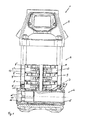
- Fig. 1 shows a multistage pump 1 according to a preferred embodiment of the invention, whereby the lower half of the pump 1 is shown in sectional view and the upper half in regular side view.
- the pump 1 can be subdivided in three sections, namely, the lowermost part of the pump 1 is formed by the base element 2, the uppermost part of the pump 1 is formed by a head element 3, and inbetween the base element 2 and the head element 3, there is arranged a pump body 4.
- fluid or in particular, water
- inlet port 5 in the base element 2
- pipe 6 so as to enter through a first hole 7 of the pipe 6 the pump body 4 in which a plurality of pump stages 8, 8', 8", etc. are provided, each having an impeller and an diffuser.
- the fluid is passed on from stage to stage upwards within a first annular space 12 surrounded by an inner pipe 9 which consists of a plurality of stackable pipe elements 9', 9", 9"', etc., whereby basically each one of the pump stages 8, 8', 8", etc. is surrounded by one of the stackable pipe elements 9', 9", 9"', etc.
- the stackable inner pipe 9 rests on an inner cup member 10 of the base element 2, which in turn is surrounded by an outer base cup 11 of the base element 2.
- the fluid after having been passed through the pump stages 8, 8', 8", etc.
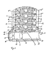
- Fig. 2 shows a detail of a lower portion of the multistage pump 1 of Fig. 1 in a cut open perspective view.
- the arrangement of a number of pump stages 8, 8', 8", 8"', etc. can be seen which are arranged one on top of the other, and each of which is surrounded by a respective element 9', 9", 9"', 9"", etc. of the stackable inner pipe 9.
- the elements 9', 9", 9"', 9"", etc. are connected to each other and together form the inner pipe 9.
- the lowermost member of the stackable inner pipe 9 rests on and is connected to the inner cup member 10 of the base element 2.
- the outer jacket of the pump 1 in its middle and lower sections is formed by the outer sleeve 14 encasing the pump body 4 with the plurality of pump stages 8, 8', 8", 8"', etc., and the outer base cup 11 of the base element 4.
- the base element 2 has an inlet port 5 and an outlet port 16 arranged at the opposing side at the circumference of the base cup 11.
- the inlet port 5 and the outlet port 16 are mechanically connected to each other by the pipe 6 which passes through the annular space 30 formed between the outer base cup 11 and the inner cup member 10 as well as through the interior space of inner cup member 10 itself, forming a suction chamber of the base element 1.
- a disk-shaped member 17 which basically has the same or a just slightly smaller diameter as the inner diameter of the pipe 6 so as to seal a low pressure section 18 on the inlet side of the pipe 6 from a high pressure section 19 at the outlet side of the pipe 6.
- both ends of the pipe 6 are provided with respective connecting pieces 20, 20' for connecting the pump 1 to respective external inflow and outflow pipes not shown here.
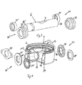
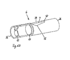
- FIG. 3 shows the pipe 6 as well as the respective connecting pieces 20, 20' for a multistage pump 1 according to embodiments of the invention in an exploded view.
- Each one of the connecting pieces 20, 20' can be formed for example by a sleeve 21, 21' which is substantially cylindrical, or by a stepped sleeve 22, 22'.
- the connecting pieces 20, 20' to be fitted on the pipe 6 at the suction or inlet side and the pressure or outlet side of the pump 1 are identical and connected to the pipe by welding
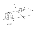
- Fig.4 shows a base element 2 including the pipe 6 and connecting pieces 20, 20' for a pump 1 according further embodiments of the invention.
- the connecting piece 20, 20' can consist of, a flange part 23, 23', a ring part 24, 24', or a ring part 25, 25' to be fixedly connected to the respective pipe end 26, 26', for example, by welding.
- Fig. 3 and 4 show different examples of connecting pieces 20, 20' which make clear that it is very easy to adapt this pump to any connecting system.
- Fig. 5 shows a perspective view of the base element 2, partially cut open at the outlet end of the pipe 6 and base cup 11.
- the ring part 25, 25' is fixedly connected to the pipe end 26' at the outlet or pressure side of the pump 1 by means of welding.
- the pipe 6 is connected to the base cup 11 by welding and to the inner cup member 10 by expanding so that sufficient mechanical strength is provided for the base element 2 of the pump 1, since the components of the base element 2, namely, the base cup 11 and the inner cup member 10 are formed from sheet metal.
- the disc-shaped member 17 is arranged within the pipe 6 between the first hole 7 on the inlet side or low pressure side, and the plurality of second holes 15 on the outlet side or high pressure side so as to sealingly separate the low pressure section 18 from a high pressure section 19.
- Fig. 6A and Fig. 6B respectively show perspective views of the pipe 6 of the multistage pump shown in Fig. 1 , whereby Fig. 6B shows the outlet side of the pipe 6 or high pressure section 19 with the front part of the pipe 6 cut out so that the arrangement of the disc-shaped member 17 between the first hole 7 and the plurality of second holes 15 can be seen. Further, it can be seen that the first hole is arranged at an upper or top part of the pipe 6 which, when assembled in the base element 2 and to the pump 1 is directed towards the pump body 4 or the annular space 12 in which the pump stages 8, 8', 8", etc. are arranged.
- the first hole 7 has an elongated shape with rounded corners 27 and substantially V-shaped recesses 28 at at least one of the lateral edges 29 of the first hole 7. This hole 7 is part of the suction mouth of the first pumpstage.
- the second holes 15 are arranged symmetrically around the outer circumference of the pipe 6 at the outlet end and are substantially rectangular, whereby all second holes 15 are formed identically and spaced apart from each other at equal distances.
- the multistage pump 1 being provided with the pipe 6 arranged within the outer base 11 of the base member 2 acts as a stiffening element and provides for sufficient strength when using sheet metal as material for the member of the base member 2.
Landscapes
- Engineering & Computer Science (AREA)
- General Engineering & Computer Science (AREA)
- Mechanical Engineering (AREA)
- Structures Of Non-Positive Displacement Pumps (AREA)
Priority Applications (3)
| Application Number | Priority Date | Filing Date | Title |
|---|---|---|---|
| EP15197535.6A EP3176441B1 (de) | 2015-12-02 | 2015-12-02 | Mehrstufige pumpe |
| US15/367,436 US10900495B2 (en) | 2015-12-02 | 2016-12-02 | Multistage pump |
| CN201611099807.0A CN107013466B (zh) | 2015-12-02 | 2016-12-02 | 多级泵 |
Applications Claiming Priority (1)
| Application Number | Priority Date | Filing Date | Title |
|---|---|---|---|
| EP15197535.6A EP3176441B1 (de) | 2015-12-02 | 2015-12-02 | Mehrstufige pumpe |
Publications (2)
| Publication Number | Publication Date |
|---|---|
| EP3176441A1 true EP3176441A1 (de) | 2017-06-07 |
| EP3176441B1 EP3176441B1 (de) | 2021-09-15 |
Family
ID=54780163
Family Applications (1)
| Application Number | Title | Priority Date | Filing Date |
|---|---|---|---|
| EP15197535.6A Not-in-force EP3176441B1 (de) | 2015-12-02 | 2015-12-02 | Mehrstufige pumpe |
Country Status (3)
| Country | Link |
|---|---|
| US (1) | US10900495B2 (de) |
| EP (1) | EP3176441B1 (de) |
| CN (1) | CN107013466B (de) |
Families Citing this family (1)
| Publication number | Priority date | Publication date | Assignee | Title |
|---|---|---|---|---|
| CN110967163B (zh) * | 2019-10-18 | 2020-10-02 | 清华大学 | 一种深邃泵站及扩压器综合试验台及其使用方法 |
Citations (4)
| Publication number | Priority date | Publication date | Assignee | Title |
|---|---|---|---|---|
| US5030061A (en) * | 1988-06-01 | 1991-07-09 | Ksb Aktiengesellschaft | Casing for inline centrifugal pumps |
| US5385444A (en) * | 1992-04-14 | 1995-01-31 | Ebara Corporation | Pump casing made of sheet metal |
| US5961301A (en) * | 1997-07-31 | 1999-10-05 | Ansimag Incorporated | Magnetic-drive assembly for a multistage centrifugal pump |
| CN103807179A (zh) * | 2012-11-08 | 2014-05-21 | 上海连成(集团)有限公司 | 一种新型的自平衡型立式多级泵 |
Family Cites Families (6)
| Publication number | Priority date | Publication date | Assignee | Title |
|---|---|---|---|---|
| DE1703908A1 (de) * | 1968-07-27 | 1972-03-23 | Grundfos As | Pumpengehaeuse fuer Kreiselpumpen |
| JP3986317B2 (ja) * | 2002-01-21 | 2007-10-03 | 株式会社荏原製作所 | 多段ポンプ |
| WO2008071592A1 (en) * | 2006-12-14 | 2008-06-19 | Dab Pumps S.P.A. | Hydraulic pump |
| EP2112380A1 (de) * | 2008-04-21 | 2009-10-28 | DP Industries B.V. | Mehrstufige Kreiselpumpe in Inline-Bauart |
| CN102312840A (zh) * | 2011-09-02 | 2012-01-11 | 南方泵业股份有限公司 | 一种高压多级离心泵 |
| CN203081864U (zh) * | 2013-01-25 | 2013-07-24 | 台州新宏基泵业有限公司 | 不锈钢立式多级离心泵进出水体 |
-
2015
- 2015-12-02 EP EP15197535.6A patent/EP3176441B1/de not_active Not-in-force
-
2016
- 2016-12-02 US US15/367,436 patent/US10900495B2/en active Active
- 2016-12-02 CN CN201611099807.0A patent/CN107013466B/zh not_active Expired - Fee Related
Patent Citations (4)
| Publication number | Priority date | Publication date | Assignee | Title |
|---|---|---|---|---|
| US5030061A (en) * | 1988-06-01 | 1991-07-09 | Ksb Aktiengesellschaft | Casing for inline centrifugal pumps |
| US5385444A (en) * | 1992-04-14 | 1995-01-31 | Ebara Corporation | Pump casing made of sheet metal |
| US5961301A (en) * | 1997-07-31 | 1999-10-05 | Ansimag Incorporated | Magnetic-drive assembly for a multistage centrifugal pump |
| CN103807179A (zh) * | 2012-11-08 | 2014-05-21 | 上海连成(集团)有限公司 | 一种新型的自平衡型立式多级泵 |
Also Published As
| Publication number | Publication date |
|---|---|
| CN107013466B (zh) | 2019-05-03 |
| CN107013466A (zh) | 2017-08-04 |
| EP3176441B1 (de) | 2021-09-15 |
| US10900495B2 (en) | 2021-01-26 |
| US20170159672A1 (en) | 2017-06-08 |
Similar Documents
| Publication | Publication Date | Title |
|---|---|---|
| RU2012106220A (ru) | Газоочистной сепаратор | |
| CN107126743B (zh) | 滤水组件 | |
| EP1563894A4 (de) | Mehrrohrtrennmembranmodul | |
| US20090274555A1 (en) | Multiple-stage centrifugal pump of inline design | |
| EP2474743A3 (de) | Fassartige Mehrstufenpumpe | |
| MX387121B (es) | Ensamblaje de filtro que incluye una tapa de flujo. | |
| JP6402247B2 (ja) | エアポンプ | |
| EP3176441B1 (de) | Mehrstufige pumpe | |
| US10844874B2 (en) | Inlet device for a vertical pump and an arrangement comprising such an inlet device | |
| EP2425136B1 (de) | Doppelmembranpumpen | |
| US20020134724A1 (en) | Apparatus for filtering and separating fluids | |
| EP3047145B1 (de) | Akustikfilter eines hermetischen verdichters | |
| CN105526195A (zh) | 多级离心泵 | |
| AU2012265619B2 (en) | Centrifugal pump | |
| RU2004131507A (ru) | Вставной клапан для радиатора, в частности секционного | |
| JP5784636B2 (ja) | 定量ポンプ | |
| CN204419606U (zh) | 高位储水引导装置及自吸泵 | |
| EP2678568B1 (de) | Anordnung einer seitenkanalmaschine | |
| RU2020112678A (ru) | Стабилизатор потока для регулирующего клапана | |
| JP6405049B2 (ja) | エアポンプ | |
| CN105756946B (zh) | 一种自吸泵 | |
| JP5791345B2 (ja) | 気液分離器 | |
| JP6596545B1 (ja) | 縦型多段ポンプ | |
| US20180045353A1 (en) | Damping device | |
| JPWO2021131048A5 (de) |
Legal Events
| Date | Code | Title | Description |
|---|---|---|---|
| AK | Designated contracting states |
Kind code of ref document: A1 Designated state(s): AL AT BE BG CH CY CZ DE DK EE ES FI FR GB GR HR HU IE IS IT LI LT LU LV MC MK MT NL NO PL PT RO RS SE SI SK SM TR |
|
| AX | Request for extension of the european patent |
Extension state: BA ME |
|
| PUAI | Public reference made under article 153(3) epc to a published international application that has entered the european phase |
Free format text: ORIGINAL CODE: 0009012 |
|
| STAA | Information on the status of an ep patent application or granted ep patent |
Free format text: STATUS: THE APPLICATION HAS BEEN PUBLISHED |
|
| STAA | Information on the status of an ep patent application or granted ep patent |
Free format text: STATUS: REQUEST FOR EXAMINATION WAS MADE |
|
| 17P | Request for examination filed |
Effective date: 20171206 |
|
| RBV | Designated contracting states (corrected) |
Designated state(s): AL AT BE BG CH CY CZ DE DK EE ES FI FR GB GR HR HU IE IS IT LI LT LU LV MC MK MT NL NO PL PT RO RS SE SI SK SM TR |
|
| GRAP | Despatch of communication of intention to grant a patent |
Free format text: ORIGINAL CODE: EPIDOSNIGR1 |
|
| STAA | Information on the status of an ep patent application or granted ep patent |
Free format text: STATUS: GRANT OF PATENT IS INTENDED |
|
| INTG | Intention to grant announced |
Effective date: 20210429 |
|
| GRAS | Grant fee paid |
Free format text: ORIGINAL CODE: EPIDOSNIGR3 |
|
| GRAA | (expected) grant |
Free format text: ORIGINAL CODE: 0009210 |
|
| STAA | Information on the status of an ep patent application or granted ep patent |
Free format text: STATUS: THE PATENT HAS BEEN GRANTED |
|
| AK | Designated contracting states |
Kind code of ref document: B1 Designated state(s): AL AT BE BG CH CY CZ DE DK EE ES FI FR GB GR HR HU IE IS IT LI LT LU LV MC MK MT NL NO PL PT RO RS SE SI SK SM TR |
|
| REG | Reference to a national code |
Ref country code: CH Ref legal event code: EP Ref country code: GB Ref legal event code: FG4D |
|
| REG | Reference to a national code |
Ref country code: DE Ref legal event code: R096 Ref document number: 602015073264 Country of ref document: DE |
|
| REG | Reference to a national code |
Ref country code: IE Ref legal event code: FG4D |
|
| REG | Reference to a national code |
Ref country code: AT Ref legal event code: REF Ref document number: 1430720 Country of ref document: AT Kind code of ref document: T Effective date: 20211015 |
|
| REG | Reference to a national code |
Ref country code: LT Ref legal event code: MG9D |
|
| REG | Reference to a national code |
Ref country code: NL Ref legal event code: MP Effective date: 20210915 |
|
| PG25 | Lapsed in a contracting state [announced via postgrant information from national office to epo] |
Ref country code: RS Free format text: LAPSE BECAUSE OF FAILURE TO SUBMIT A TRANSLATION OF THE DESCRIPTION OR TO PAY THE FEE WITHIN THE PRESCRIBED TIME-LIMIT Effective date: 20210915 Ref country code: SE Free format text: LAPSE BECAUSE OF FAILURE TO SUBMIT A TRANSLATION OF THE DESCRIPTION OR TO PAY THE FEE WITHIN THE PRESCRIBED TIME-LIMIT Effective date: 20210915 Ref country code: HR Free format text: LAPSE BECAUSE OF FAILURE TO SUBMIT A TRANSLATION OF THE DESCRIPTION OR TO PAY THE FEE WITHIN THE PRESCRIBED TIME-LIMIT Effective date: 20210915 Ref country code: LT Free format text: LAPSE BECAUSE OF FAILURE TO SUBMIT A TRANSLATION OF THE DESCRIPTION OR TO PAY THE FEE WITHIN THE PRESCRIBED TIME-LIMIT Effective date: 20210915 Ref country code: BG Free format text: LAPSE BECAUSE OF FAILURE TO SUBMIT A TRANSLATION OF THE DESCRIPTION OR TO PAY THE FEE WITHIN THE PRESCRIBED TIME-LIMIT Effective date: 20211215 Ref country code: FI Free format text: LAPSE BECAUSE OF FAILURE TO SUBMIT A TRANSLATION OF THE DESCRIPTION OR TO PAY THE FEE WITHIN THE PRESCRIBED TIME-LIMIT Effective date: 20210915 Ref country code: NO Free format text: LAPSE BECAUSE OF FAILURE TO SUBMIT A TRANSLATION OF THE DESCRIPTION OR TO PAY THE FEE WITHIN THE PRESCRIBED TIME-LIMIT Effective date: 20211215 |
|
| REG | Reference to a national code |
Ref country code: AT Ref legal event code: MK05 Ref document number: 1430720 Country of ref document: AT Kind code of ref document: T Effective date: 20210915 |
|
| PG25 | Lapsed in a contracting state [announced via postgrant information from national office to epo] |
Ref country code: LV Free format text: LAPSE BECAUSE OF FAILURE TO SUBMIT A TRANSLATION OF THE DESCRIPTION OR TO PAY THE FEE WITHIN THE PRESCRIBED TIME-LIMIT Effective date: 20210915 Ref country code: GR Free format text: LAPSE BECAUSE OF FAILURE TO SUBMIT A TRANSLATION OF THE DESCRIPTION OR TO PAY THE FEE WITHIN THE PRESCRIBED TIME-LIMIT Effective date: 20211216 |
|
| PG25 | Lapsed in a contracting state [announced via postgrant information from national office to epo] |
Ref country code: AT Free format text: LAPSE BECAUSE OF FAILURE TO SUBMIT A TRANSLATION OF THE DESCRIPTION OR TO PAY THE FEE WITHIN THE PRESCRIBED TIME-LIMIT Effective date: 20210915 |
|
| PG25 | Lapsed in a contracting state [announced via postgrant information from national office to epo] |
Ref country code: IS Free format text: LAPSE BECAUSE OF FAILURE TO SUBMIT A TRANSLATION OF THE DESCRIPTION OR TO PAY THE FEE WITHIN THE PRESCRIBED TIME-LIMIT Effective date: 20220115 Ref country code: SM Free format text: LAPSE BECAUSE OF FAILURE TO SUBMIT A TRANSLATION OF THE DESCRIPTION OR TO PAY THE FEE WITHIN THE PRESCRIBED TIME-LIMIT Effective date: 20210915 Ref country code: SK Free format text: LAPSE BECAUSE OF FAILURE TO SUBMIT A TRANSLATION OF THE DESCRIPTION OR TO PAY THE FEE WITHIN THE PRESCRIBED TIME-LIMIT Effective date: 20210915 Ref country code: RO Free format text: LAPSE BECAUSE OF FAILURE TO SUBMIT A TRANSLATION OF THE DESCRIPTION OR TO PAY THE FEE WITHIN THE PRESCRIBED TIME-LIMIT Effective date: 20210915 Ref country code: PT Free format text: LAPSE BECAUSE OF FAILURE TO SUBMIT A TRANSLATION OF THE DESCRIPTION OR TO PAY THE FEE WITHIN THE PRESCRIBED TIME-LIMIT Effective date: 20220117 Ref country code: PL Free format text: LAPSE BECAUSE OF FAILURE TO SUBMIT A TRANSLATION OF THE DESCRIPTION OR TO PAY THE FEE WITHIN THE PRESCRIBED TIME-LIMIT Effective date: 20210915 Ref country code: NL Free format text: LAPSE BECAUSE OF FAILURE TO SUBMIT A TRANSLATION OF THE DESCRIPTION OR TO PAY THE FEE WITHIN THE PRESCRIBED TIME-LIMIT Effective date: 20210915 Ref country code: ES Free format text: LAPSE BECAUSE OF FAILURE TO SUBMIT A TRANSLATION OF THE DESCRIPTION OR TO PAY THE FEE WITHIN THE PRESCRIBED TIME-LIMIT Effective date: 20210915 Ref country code: EE Free format text: LAPSE BECAUSE OF FAILURE TO SUBMIT A TRANSLATION OF THE DESCRIPTION OR TO PAY THE FEE WITHIN THE PRESCRIBED TIME-LIMIT Effective date: 20210915 Ref country code: CZ Free format text: LAPSE BECAUSE OF FAILURE TO SUBMIT A TRANSLATION OF THE DESCRIPTION OR TO PAY THE FEE WITHIN THE PRESCRIBED TIME-LIMIT Effective date: 20210915 Ref country code: AL Free format text: LAPSE BECAUSE OF FAILURE TO SUBMIT A TRANSLATION OF THE DESCRIPTION OR TO PAY THE FEE WITHIN THE PRESCRIBED TIME-LIMIT Effective date: 20210915 |
|
| REG | Reference to a national code |
Ref country code: DE Ref legal event code: R097 Ref document number: 602015073264 Country of ref document: DE |
|
| PLBE | No opposition filed within time limit |
Free format text: ORIGINAL CODE: 0009261 |
|
| STAA | Information on the status of an ep patent application or granted ep patent |
Free format text: STATUS: NO OPPOSITION FILED WITHIN TIME LIMIT |
|
| PG25 | Lapsed in a contracting state [announced via postgrant information from national office to epo] |
Ref country code: MC Free format text: LAPSE BECAUSE OF FAILURE TO SUBMIT A TRANSLATION OF THE DESCRIPTION OR TO PAY THE FEE WITHIN THE PRESCRIBED TIME-LIMIT Effective date: 20210915 Ref country code: DK Free format text: LAPSE BECAUSE OF FAILURE TO SUBMIT A TRANSLATION OF THE DESCRIPTION OR TO PAY THE FEE WITHIN THE PRESCRIBED TIME-LIMIT Effective date: 20210915 |
|
| REG | Reference to a national code |
Ref country code: CH Ref legal event code: PL |
|
| 26N | No opposition filed |
Effective date: 20220616 |
|
| PG25 | Lapsed in a contracting state [announced via postgrant information from national office to epo] |
Ref country code: SI Free format text: LAPSE BECAUSE OF FAILURE TO SUBMIT A TRANSLATION OF THE DESCRIPTION OR TO PAY THE FEE WITHIN THE PRESCRIBED TIME-LIMIT Effective date: 20210915 |
|
| REG | Reference to a national code |
Ref country code: BE Ref legal event code: MM Effective date: 20211231 |
|
| REG | Reference to a national code |
Ref country code: DE Ref legal event code: R082 Ref document number: 602015073264 Country of ref document: DE |
|
| PG25 | Lapsed in a contracting state [announced via postgrant information from national office to epo] |
Ref country code: LU Free format text: LAPSE BECAUSE OF NON-PAYMENT OF DUE FEES Effective date: 20211202 Ref country code: IE Free format text: LAPSE BECAUSE OF NON-PAYMENT OF DUE FEES Effective date: 20211202 |
|
| PG25 | Lapsed in a contracting state [announced via postgrant information from national office to epo] |
Ref country code: FR Free format text: LAPSE BECAUSE OF NON-PAYMENT OF DUE FEES Effective date: 20211231 Ref country code: BE Free format text: LAPSE BECAUSE OF NON-PAYMENT OF DUE FEES Effective date: 20211231 |
|
| PG25 | Lapsed in a contracting state [announced via postgrant information from national office to epo] |
Ref country code: LI Free format text: LAPSE BECAUSE OF NON-PAYMENT OF DUE FEES Effective date: 20211231 Ref country code: CH Free format text: LAPSE BECAUSE OF NON-PAYMENT OF DUE FEES Effective date: 20211231 |
|
| PG25 | Lapsed in a contracting state [announced via postgrant information from national office to epo] |
Ref country code: IT Free format text: LAPSE BECAUSE OF FAILURE TO SUBMIT A TRANSLATION OF THE DESCRIPTION OR TO PAY THE FEE WITHIN THE PRESCRIBED TIME-LIMIT Effective date: 20210915 |
|
| PG25 | Lapsed in a contracting state [announced via postgrant information from national office to epo] |
Ref country code: HU Free format text: LAPSE BECAUSE OF FAILURE TO SUBMIT A TRANSLATION OF THE DESCRIPTION OR TO PAY THE FEE WITHIN THE PRESCRIBED TIME-LIMIT; INVALID AB INITIO Effective date: 20151202 |
|
| PG25 | Lapsed in a contracting state [announced via postgrant information from national office to epo] |
Ref country code: CY Free format text: LAPSE BECAUSE OF FAILURE TO SUBMIT A TRANSLATION OF THE DESCRIPTION OR TO PAY THE FEE WITHIN THE PRESCRIBED TIME-LIMIT Effective date: 20210915 |
|
| PGFP | Annual fee paid to national office [announced via postgrant information from national office to epo] |
Ref country code: GB Payment date: 20231220 Year of fee payment: 9 |
|
| PGFP | Annual fee paid to national office [announced via postgrant information from national office to epo] |
Ref country code: DE Payment date: 20231214 Year of fee payment: 9 |
|
| PG25 | Lapsed in a contracting state [announced via postgrant information from national office to epo] |
Ref country code: MK Free format text: LAPSE BECAUSE OF FAILURE TO SUBMIT A TRANSLATION OF THE DESCRIPTION OR TO PAY THE FEE WITHIN THE PRESCRIBED TIME-LIMIT Effective date: 20210915 |
|
| PG25 | Lapsed in a contracting state [announced via postgrant information from national office to epo] |
Ref country code: MT Free format text: LAPSE BECAUSE OF FAILURE TO SUBMIT A TRANSLATION OF THE DESCRIPTION OR TO PAY THE FEE WITHIN THE PRESCRIBED TIME-LIMIT Effective date: 20210915 |
|
| REG | Reference to a national code |
Ref country code: DE Ref legal event code: R119 Ref document number: 602015073264 Country of ref document: DE |
|
| GBPC | Gb: european patent ceased through non-payment of renewal fee |
Effective date: 20241202 |
|
| PG25 | Lapsed in a contracting state [announced via postgrant information from national office to epo] |
Ref country code: DE Free format text: LAPSE BECAUSE OF NON-PAYMENT OF DUE FEES Effective date: 20250701 |
|
| PG25 | Lapsed in a contracting state [announced via postgrant information from national office to epo] |
Ref country code: GB Free format text: LAPSE BECAUSE OF NON-PAYMENT OF DUE FEES Effective date: 20241202 |
|
| PG25 | Lapsed in a contracting state [announced via postgrant information from national office to epo] |
Ref country code: TR Free format text: LAPSE BECAUSE OF FAILURE TO SUBMIT A TRANSLATION OF THE DESCRIPTION OR TO PAY THE FEE WITHIN THE PRESCRIBED TIME-LIMIT Effective date: 20210915 |