EP3176534A2 - Vorrichtung und verfahren zur reinigung eines wärmetauschers - Google Patents
Vorrichtung und verfahren zur reinigung eines wärmetauschers Download PDFInfo
- Publication number
- EP3176534A2 EP3176534A2 EP16201397.3A EP16201397A EP3176534A2 EP 3176534 A2 EP3176534 A2 EP 3176534A2 EP 16201397 A EP16201397 A EP 16201397A EP 3176534 A2 EP3176534 A2 EP 3176534A2
- Authority
- EP
- European Patent Office
- Prior art keywords
- heat exchanger
- evaporation module
- cleaning device
- cleaning
- evaporation
- Prior art date
- Legal status (The legal status is an assumption and is not a legal conclusion. Google has not performed a legal analysis and makes no representation as to the accuracy of the status listed.)
- Granted
Links
Images

Classifications
-
- F—MECHANICAL ENGINEERING; LIGHTING; HEATING; WEAPONS; BLASTING
- F28—HEAT EXCHANGE IN GENERAL
- F28G—CLEANING OF INTERNAL OR EXTERNAL SURFACES OF HEAT-EXCHANGE OR HEAT-TRANSFER CONDUITS, e.g. WATER TUBES OR BOILERS
- F28G1/00—Non-rotary, e.g. reciprocated, appliances
- F28G1/16—Non-rotary, e.g. reciprocated, appliances using jets of fluid for removing debris
- F28G1/166—Non-rotary, e.g. reciprocated, appliances using jets of fluid for removing debris from external surfaces of heat exchange conduits
-
- F—MECHANICAL ENGINEERING; LIGHTING; HEATING; WEAPONS; BLASTING
- F02—COMBUSTION ENGINES; HOT-GAS OR COMBUSTION-PRODUCT ENGINE PLANTS
- F02G—HOT GAS OR COMBUSTION-PRODUCT POSITIVE-DISPLACEMENT ENGINE PLANTS; USE OF WASTE HEAT OF COMBUSTION ENGINES; NOT OTHERWISE PROVIDED FOR
- F02G1/00—Hot gas positive-displacement engine plants
- F02G1/04—Hot gas positive-displacement engine plants of closed-cycle type
- F02G1/043—Hot gas positive-displacement engine plants of closed-cycle type the engine being operated by expansion and contraction of a mass of working gas which is heated and cooled in one of a plurality of constantly communicating expansible chambers, e.g. Stirling cycle type engines
- F02G1/053—Component parts or details
- F02G1/055—Heaters or coolers
-
- F—MECHANICAL ENGINEERING; LIGHTING; HEATING; WEAPONS; BLASTING
- F02—COMBUSTION ENGINES; HOT-GAS OR COMBUSTION-PRODUCT ENGINE PLANTS
- F02G—HOT GAS OR COMBUSTION-PRODUCT POSITIVE-DISPLACEMENT ENGINE PLANTS; USE OF WASTE HEAT OF COMBUSTION ENGINES; NOT OTHERWISE PROVIDED FOR
- F02G2254/00—Heat inputs
Definitions
- the invention is in the field of heat exchangers and relates in particular to the purification of heat exchangers which come into contact with flue gases.
- a combined heat and power by means of Stirling engines has the advantage that the hot flue gases (eg flue gases produced in biomass combustion plants) are separated from the process gas of the engine and the heat transfer to the process gas takes place via a heat exchanger to which However, accumulate for the reasons described above, ash particles and other particles contained in the flue gas, which deteriorates the heat transfer in the heat exchanger.
- the hot flue gases eg flue gases produced in biomass combustion plants
- the object underlying the invention can be seen to provide an improved apparatus and an improved method for cleaning a heat exchanger in a cogeneration machine.
- the cleaning device has an evaporation module which is arranged in the vicinity of the heat exchanger, so that it is exposed to the same gas flow as the heat exchanger.
- the cleaning device further comprises a supply line, which is connected to the evaporation module and via which a liquid can be passed into the evaporation module.
- the evaporation module has outlet nozzles which are arranged so that the vapor, which is formed in the evaporation module by evaporation of the liquid, can exit through the outlet nozzles in the direction of the heat exchanger.
- Stirling engine This has, according to an embodiment of the invention, a heat exchanger (heater), which is flowed through by hot hot gas, so that the heating gas gives off heat to the heat exchanger.
- the Stirling engine further includes the above-described cleaning device located near the heat exchanger.
- the method comprises the method of feeding a defined amount of liquid into the evaporation module, wherein the liquid in vaporizes the evaporation module and steam exits through outlet nozzles of the evaporation module in the direction of the heat exchanger.
- the embodiments of a cleaning device described here are designed to generate high-pressure steam within an evaporation module of the cleaning device and to direct it via outlet nozzles to the heat exchanger to be cleaned.
- the embodiments described here relate to a cleaning device for cleaning a heat exchanger of a Stirling engine.
- the cleaning device can also be used in other environments for cleaning heat exchangers.
- the evaporation module of the cleaning device can be arranged, for example, where the heating gases that heat the heat exchanger, leaving this.
- the module assumes the temperature of the exiting hot gases, which in the case of Stirling machines or other thermodynamic machines can be up to 700 degrees Celsius.
- a defined amount of liquid eg water
- the steam then exits the module at high pressure on nozzles with the nozzles aligned so that the steam is directed onto the surface of the heat exchanger to be cleaned.
- This process can be cyclically controlled, for example, time-dependent or depending on the degree of contamination of the heat exchanger.
- the cleaning device described here offers the possibility of pivoting the evaporation module about its longitudinal axis in order to gradually spray the surface of the heat exchanger with only a limited number of nozzles, which causes a particularly intensive partial cleaning.
- the cleaning can be done without interrupting the operation of the machine and the superheated steam jet does not cause a damaging temperature shock at the heat exchanger.
- the invention is eminently suitable for removing dust and particulate deposits from the heat exchanger without the use of external energy. Rather, the temperature level of the flue gases is used when exiting the heat exchanger to heat the evaporation module of the cleaning device. While the hot gases (flue gases) can flow with temperatures of over 1200 degrees Celsius on the heat exchanger, they cool at the surfaces of the heat exchanger whose temperatures are about 600 to 650 degrees C, to about 700 degrees C from. Depending on the design of the Stirling engine as a medium or high-temperature machine, this value can still vary significantly upwards or downwards. In any case, however, it is a temperature level at which on the one hand materials such as steels are still available with considerable strengths, on the other hand, a highly superheated steam with pressures of more than 100 bar can be generated.
- the evaporation module is, for example, a cuboid or cylindrical body comprising a housing, for example of heat-resistant steel.
- the housing is filled with a material with high heat capacity, for example made of alloy steel, and is immediately (relative to the flow direction of the hot gases) arranged behind the heat exchanger, so that the evaporation module is heated by the hot gases over time substantially to their temperature.
- a material with high heat capacity for example made of alloy steel
- the input side are connected to a water supply line and the output side with one or more outlet nozzles.
- the nozzles may be arranged in rows and are directed to the heat exchanger.
- the evaporation module is supplied via a pipe, in the course of which is a check valve, cyclically supplied via a water supply device with a defined amount of water.
- the check valve protects the water supply device against pressure surges (shock waves) that may arise during the evaporation process in the evaporation module.
- the water supply may optionally comprise a high-pressure line, a pump or a pump cylinder, which emits the defined amount of water to the evaporation module.
- a high-pressure shut-off valve may allow the controlled supply of certain amounts of water at certain time intervals, which are adapted to the cleaning requirements of the heat exchanger. In the case of the application of a pump cylinder, a high-pressure shut-off valve (solenoid valve 3.2) is unnecessary, since the supply of a defined amount of water depends directly on the stroke of the pump cylinder.
- the number of exit nozzles on the evaporation module and their orientation can be chosen so that they cover the entire heat exchanger. It may be advantageous in view of a short-term Schugasumledge to clean only a portion of the heat exchanger.
- the concomitant reduction in the number of nozzles can be used for faster pressure build-up and higher final pressure resulting in significantly more concentrated cleaning.
- To operate the entire heat exchanger surface it may be provided to pivot or displace the evaporator continuously or stepwise.
- the water supply can be done via a flexible hose or a rotary feedthrough. Such are known per se and therefore need no further explanation here, as well as a pivoting or Verschubmechanismus for the evaporation module by step or pivot motors here requires no further explanation.
- cleaning the heat exchanger does not require service interruption and that the purge jet is superheated steam, so that there is no thermal shock on the heat exchanger surface is triggered, as would be the case for example with cold compressed air or even with cold liquids.
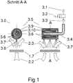
- FIG. 1 schematically shows a simple example of the cleaning device 3.0 generally described above, which is in the vicinity of a heat exchanger 1.7 (which may be part of a Stirling machine 1.0, for example, see also Fig. 2 ).
- the hot fuel gas 2.2 is generated by a furnace 2.0, not shown.
- FIG. 1 shows right longitudinal section through the evaporation module 3.5 of the cleaning device 3.0 and left a corresponding cross-section.
- the evaporation module 3.5 has a housing 3.9, which can be made of heat-resistant steel, for example.
- the housing 3.9 is filled with a material 3.10 high heat capacity (eg alloy steel), are provided in the channels 3.6.
- the water supplied via the supply line 3.4 to the evaporation module 3.5 is vaporized while the channels 3.6. flows through abruptly, and the resulting steam exits through the outlet nozzle 3.7, in which the channels open 3.6, from.
- the resulting steam jet 3.8 is directed to the heat exchanger 1.7 and frees it from the aforementioned deposits.
- the volume of water supplied to the evaporation module 3.5 is determined via the valves 3.2 and 3.3 connected in series.
- the valve 3.2 may be, for example, a solenoid valve which is driven at regular intervals to open the valve for a short time.
- the second valve 3.3 is a check valve, which closes due to the resulting in the sudden evaporation of the supplied water pressure wave in the supply line 3.4 and prevents backflow of the water in the supply line 3.4.
- the solenoid valve 3.2 and the water supply is protected from the pressure wave.
- the water supply 3.1 can also consist of a pump cylinder 3.11, which is cyclically actuated and a metered amount of water to the evaporation module 3.5 supplies (see also Fig. 4 ).
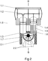
- FIG. 2 shows a longitudinal section along the cylinder axes and Fig. 3 a corresponding cross section through the cleaning device 3.0.
- the Stirling engine 1.0 includes two cylinders 1.3 and 1.4, in each of which a piston is guided.
- the pistons are mechanically coupled to the crankshaft 1.2 so that the linear motion of the pistons is converted into rotational motion of the crankshaft.
- the pistons move linearly along the cylinder axes, which are approximately parallel in the present example (which need not necessarily be the case).
- the cylinder 1.3 is “hot” and the cylinder 1.4 is “cold”, wherein the cold cylinder 1.3 lags the hot by a certain phase angle (based on the rotation angle of the crankshaft 1.2).
- the crankshaft 1.2 is arranged in a housing, the crankcase 1.1.
- a regenerator 1.6 is arranged at the cylinder end of the cold cylinder 1.4.
- the high-temperature heat exchanger 1.7 (heater) is arranged, which comes into operation during operation with the hot fuel gas 2.2 (eg over 1000 ° C.) and thus by deposits of dust, ash and other particles , which carries the fuel gas 2.2 with it, is charged.
- the heating gas 2.2 gives heat to the heat exchanger 1.7, thereby cooling to e.g. around 700 ° C.
- the cooled, but still warm fuel gas is designated by the reference numeral 2.3.
- Around the heat exchanger 1.7 around a heating gas 2.1 is arranged, which ensures that the heating gas flows through the heat exchanger 1.7.
- the operation of a Stirling machine in alpha configuration is known per se and will not be explained further here.
- the heater or heat exchanger 1.7 extends arcuately (approximately semicircular in longitudinal section Fig. 2 ) between the two cylinders 1.3 and 1.4, and consists of several channels, which are traversed by the process gas of the Stirling engine. Other than arcuate compounds may be advantageous in specific applications, but do not affect the idea of the invention.
- the cleaning device 3.0 is arranged in the immediate vicinity of the heat exchanger 1.7, that it is flowed around by the warm (cooled to eg about 700 ° C.) heating gas and heated. In operation, therefore, the cleaning device 3.0 has approximately the same temperature as the warm fuel gas 2.3.
- the heat exchanger 1.7 extends arcuately in such a way that at least partially surrounds the cleaning direction 3.0.
- the longitudinal axis of the cleaning device 3.0 is approximately in the center of the arc.
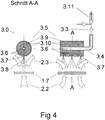
- FIG. 4 shows the same example Fig. 1 with an alternative water supply instead of a pressure port of the check valve 3.3 is preceded by a pump cylinder 3.11.
- the solenoid valve 3.2 can be omitted in this case.
- the evaporation module 3.5 Upon actuation of the pump cylinder 3.11 the evaporation module 3.5 a defined amount of liquid via the check valve 3.3 is supplied. This defined amount of liquid depends directly on the geometry (cross-sectional area and stroke) of the pumping cylinder 3.11, which can be matched to the evaporation module 3.5.
- the cleaning process may be cyclically controlled (for example, time dependent or depending on the degree of fouling of the heat exchanger), with the pump cylinder being operated once in each cycle to inject the defined amount of liquid into the evaporation module 3.5.
- Fig. 4 identical with Fig. 1 ,
Landscapes
- Engineering & Computer Science (AREA)
- Chemical & Material Sciences (AREA)
- Combustion & Propulsion (AREA)
- Mechanical Engineering (AREA)
- General Engineering & Computer Science (AREA)
- Cleaning By Liquid Or Steam (AREA)
- Cleaning Or Drying Semiconductors (AREA)
Abstract
Description
- Die Erfindung liegt auf dem Gebiet der Wärmetauscher und betrifft insbesondere die Reinigung von Wärmetauschern, die mit Rauchgasen in Berührung kommen.
- Die direkte Nutzung der heißen Rauchgase aus Biomasse-Verbrennungsanlagen für Kraft-Wärme-Kopplungsmaschinen bedeutet eine dramatische Systemvereinfachung im Vergleich zu beispielsweise einem Holzgas-Blockheizkraftwerk. Letzteres benötigen eine Vergaseranlage, eine Gaskühlung und eine Teerkondensationsanlage, bevor das resultierende Gas einem Ottomotor zugeführt werden kann. Abgesehen davon, dass wegen der Gaskühlung der elektrische Gesamtwirkungsgrad sinkt, steigt infolge der Anzahl der Systemkomponenten der Aufwand für Wartung und Instandhaltung. Jedoch auch andere Brennstoffe, wie beispielsweise Deponie- oder Klärgase (Schwachgase) beinhalten Reststoffe, die bei der Verbrennung zu Ablagerungen am Wärmetauscher führen. Typisches Beispiel dafür sind Siloxane in Klärgasen, die bei der Verbrennung in Form von Siliciumdioxid ausfallen.
- Eine Kraft-Wärme-Kopplung mittels Stirling-Motoren hat den Vorteil, dass die heißen Rauchgase (z.B. Rauchgase, die in Biomasse-Feuerungsanlagen entstehen) von dem Prozessgas des Motors getrennt sind und die Wärmeübertragung auf das Prozessgas über einen Wärmetauscher erfolgt, an dem sich jedoch aus den oben beschriebenen Gründen Ascheteile und andere im Rauchgas enthaltenen Partikel anlagern, was die Wärmeübertragung im Wärmetauscher verschlechtert.
- Es sind verschiedene Reinigungsvorrichtungen zur Reinigung von Wärmetauscher bekannt, die beispielsweise mechanisch wirken oder mit Druckluft oder Dampf betrieben werden. Der Aufsatz Marinitsch et al.: "Development of a hot gas heat exchanger an a cleaning system for a 35 kWel hermetic four cylinder stirling engine for solid biomass", in: Proceedings of the 12th ISEC, Sept. 2005, beschreibt die automatische Reinigung eines Wärmetauschers mittels Pressluft. An anderen Stellen wird auf den schädlichen Einfluss von Siloxanen berichtet, die in Verbrennungsmotoren in Form von Quarzstaub ausfallen und zu erheblichen Schäden, jedenfalls zu erhöhtem Instandsetzungsaufwand führen. In der Publikation
EP 1 988 352 A2 ist ein System beschrieben, bei dem der Wärmetauscher mit einer Art Bürste mechanisch gereinigt wird. - Die der Erfindung zugrunde liegende Aufgabe kann darin gesehen werden ein eine verbesserte Vorrichtung sowie eine verbessertes Verfahren zur Reinigung eines Wärmetauschers in einer Kraft-Wärme-Kopplungs-Maschine zu schaffen.
- Die oben genannte Aufgabe wird durch eine Vorrichtung gemäß Anspruch 1 und 8 sowie durch ein Verfahren gemäß Anspruch 12 gelöst. Verschiedene Ausführungsformen und Weiterentwicklungen der Erfindung sind Gegenstand der abhängigen Ansprüche.
- Es wird eine Vorrichtung zur Reinigung eines Wärmetauschers beschrieben. Gemäß einem Ausführungsbeispiel der Erfindung weist die Reinigungsvorrichtung ein Verdampfungsmodul auf, das in der Nähe des Wärmetauschers angeordnet ist, sodass es derselben Gasströmung ausgesetzt ist wie der Wärmetauscher. Die Reinigungsvorrichtung weist des Weiteren eine Zuleitung auf, die mit dem Verdampfungsmodul verbunden ist und über die eine Flüssigkeit in das Verdampfungsmodul geleitet werden kann. Das Verdampfungsmodul weist Auslassdüsen auf, die so angeordnet sind, das Dampf, der in dem Verdampfungsmodul durch Verdampfen der Flüssigkeit entsteht, durch die Auslassdüsen in Richtung des Wärmetauschers austreten kann.
- Des Weiteren wird ein Stirling-Motor beschrieben. Dieser weist gemäß einem Ausführungsbeispiel der Erfindung einen Wärmetauscher (Erhitzer) auf, der von heißem Heizgas angeströmt wird, sodass das Heizgas Wärme an den Wärmetauscher abgibt. Der Stirling-Motor weist des Weiteren die oben beschriebene Reinigungsvorrichtung auf, die in der Nähe des Wärmetauschers angeordnet ist.
- Schließlich wird ein Verfahren zur Reinigung eines Wärmetauschers beschrieben. Dazu wird ein Verdampfungsmodul verwendet, welches in der Nähe des Wärmetauschers angeordnet ist, sodass es derselben Gasströmung ausgesetzt ist wie der Wärmetauscher. Gemäß einem Beispiel der Erfindung umfasst das Verfahren das Verfahren das Zuführen einer definierten Flüssigkeitsmenge in das Verdampfungsmodul, wobei die Flüssigkeit in dem Verdampfungsmodul verdampft und Dampf durch Auslassdüsen des Verdampfungsmoduls in Richtung des Wärmetauschers austritt.
- Die Erfindung wird nachfolgend anhand von den in den Abbildungen dargestellten Beispielen näher erläutert. Die Darstellungen sind nicht zwangsläufig maßstabsgetreu und die Erfindung beschränkt sich nicht nur auf die dargestellten Aspekte. Vielmehr wird Wert darauf gelegt, die der Erfindung zugrunde liegenden Prinzipien darzustellen. Zu den Abbildungen:
-
Figur 1 zeigt das Reinigungssystem in tlw. vereinfachter Darstellung. -
Figur 2 zeigt beispielhaft eine Anwendung der Erfindung an einer Stirling-Maschine in Alpha-Konfiguration. -
Figur 3 zeigt einen Längsschnitt durch die Stirling-Maschine gemäßFig. 2 . -
Figur 4 zeigt das Beispiel ausFig. 1 mit einer alternativen Wasserversorgung. - In den Abbildungen bezeichnen gleiche Bezugszeichen gleiche oder Ähnliche Komponenten mit gleicher oder ähnlicher Bedeutung.
- Die hier beschriebenen Ausführungsbeispiele einer Reinigungsvorrichtung sind dazu ausgebildet, innerhalb eines Verdampfungsmoduls der Reinigungsvorrichtung Hochdruckdampf zu generieren und diesen über Austrittsdüsen auf den zu reinigenden Wärmetauscher zu leiten. Die hier beschriebenen Ausführungsbeispiele betreffen eine Reinigungsvorrichtung zum Reinigen eines Wärmetauschers einer Stirling-Maschine. Die Reinigungsvorrichtung kann jedoch auch in anderen Umgebungen zur Reinigung von Wärmetauschern eingesetzt werden.
- Das Verdampfungsmodul der Reinigungsvorrichtung kann beispielsweise dort angeordnet werden, wo die Heizgase, die den Wärmetauscher heizen, diesen verlassen. Im Betrieb nimmt nach einer gewissen Zeit das Modul die Temperatur der austretenden Heizgase an, die im Fall von Stirling-Maschinen oder anderen thermodynamischen Maschinen bis zu 700 Grad Celsius betragen können. Gemäß den hier beschriebenen Ausführungsbeispielen wird dem heißen Modul eine definierte Menge Flüssigkeit (z.B. Wasser) zugeführt, die in Kanälen, welche innerhalb des Moduls vorgesehen sind, schlagartig zu Dampf umgewandelt wird. Der Dampf tritt dann mit hohem Druck an Düsen aus dem Modul aus, wobei die Düsen so ausgerichtet sind, dass der Dampf auf die zu reinigende Oberfläche des Wärmetauschers geleitet wird. Dieser Vorgang kann zyklisch gesteuert werden, beispielsweis zeitabhängig oder abhängig vom Grad der Verschmutzung des Wärmetauschers. Darüber hinaus bietet die hier beschriebene Reinigungsvorrichtung die Möglichkeit, das Verdampfungsmodul um seine Längsachse zu schwenken, um nur mit einer begrenzten Anzahl an Düsen schrittweise die Oberfläche des Wärmetauschers zu besprühen, was eine besonders intensive Teilreinigung bewirkt. Die Reinigung kann ohne Betriebsunterbrechung der Maschine erfolgen und der überhitzte Dampfstrahl bewirkt keinen schädlichen Temperaturschock am Wärmetauscher.
- Die Erfindung eignet sich hervorragend dafür, staub- und partikelartige Ablagerungen vom Wärmetauscher ohne den Einsatz von externer Energie zu entfernen. Vielmehr wird das Temperaturniveau der Rauchgase beim Austritt aus dem Wärmetauscher genutzt, um das Verdampfungsmodul der Reinigungsvorrichtung zu heizen. Während die Heizgase (Rauchgase) mit Temperaturen von über 1200 Grad Celsius auf den Wärmetauscher zuströmen können, kühlen sie an den Oberflächen des Wärmetauschers, deren Temperaturen etwa 600 bis 650 Grad C betragen, auf etwa 700 Grad C ab. Je nach Auslegung der Stirling-Maschine als Mittel- oder Hochtemperaturmaschine, kann dieser Wert noch erheblich nach oben oder nach unten variieren. In jedem Fall handelt es sich jedoch um ein Temperaturniveau, bei dem einerseits Werkstoffe wie Stähle noch mit erheblichen Festigkeiten verfügbar sind, andererseits ein hoch überhitzter Dampf mit Drücken von mehr als 100 bar erzeugbar ist.
- Das Verdampfungsmodul ist beispielsweise ein quaderförmiger oder zylindrischer Körper umfassend ein Gehäuse, z.B. aus warmfestem Stahl. Das Gehäuse ist ausgefüllt mit einem Material mit hoher Wärmekapazität, z.B. aus legiertem Stahl, und ist unmittelbar (bezogen auf die Strömungsrichtung der Heizgase) hinter dem Wärmetauscher angeordnet, sodass das Verdampfungsmodul von den Heizgasen im Laufe der Zeit im Wesentlichen auf deren Temperatur erhitzt wird. Im Inneren des Zylinders befinden sich im Bereich des Materials mit hoher Wärmekapazität Kanäle mit möglichst hoher Oberfläche, die eingangsseitig mit einer Wasserzuleitung und ausgangsseitig mit einer oder mehreren Austrittdüsen verbunden sind. Die Düsen können in Reihen angeordnet sein und sind auf den Wärmetauscher gerichtet.
- Das Verdampfungsmodul wird über eine Rohrleitung, in deren Verlauf sich ein Rückschlagventil befindet, zyklisch über eine Wasserversorgungseinrichtung mit einer definierten Wassermenge versorgt. Das Rückschlagventil schützt die Wasserversorgungseinrichtung vor Druckschlägen (Stoßwellen), die während des Verdampfungsvorganges in dem Verdampfungsmodul entstehen können. Die Wasserversorgung kann wahlweise eine Hochdruckleitung, eine Pumpe oder einen Pumpenzylinder umfassen, welche bzw. welcher die definierte Wassermenge an das Verdampfungsmodul abgibt. Ein Hochdruck-Absperrventil kann die gesteuerte Zuführung von bestimmten Wassermengen in bestimmten Zeitintervallen, die dem Reinigungsbedarf des Wärmetauschers angepasst sind, ermöglichen. Im Falle der Anwendung eines Pumpzylinders erübrigt sich ein Hochdruck-Absperrventil (Magnetventil 3.2), da die Zuführung einer definierten Wassermenge direkt vom Hub des Pumpzylinders abhängt.
- Die Anzahl der Austrittdüsen am Verdampfungsmodul und deren Ausrichtung können so gewählt werden, dass sie den gesamten Wärmetauscher erfassen. Es kann im Hinblick auf eine kurzfristige Heizgasumkehr vorteilhaft sein, jeweils nur einen Teil des Wärmetauschers zu reinigen. Die einhergehende Reduzierung der Anzahl der Düsen kann für einen rascheren Druckaufbau und einen höheren Enddruck genutzt werden, was zu einer erheblich konzentrierteren Reinigung führt. Um die gesamte Wärmetauscherfläche zu bedienen, kann vorgesehen sein, den Verdampfer kontinuierlich oder schrittweise zu schwenken oder zu verschieben. Die Wasserzuführung kann dabei über einen flexiblen Schlauch oder über eine Drehdurchführung erfolgen. Solche sind an sich bekannt und bedürfen daher hier keiner weiteren Erläuterung, wie auch ein Schwenk- oder Verschubmechanismus für das Verdampfungsmodul mittels Schritt- oder Schwenkmotoren hier keiner weiteren Erläuterungen bedarf.
- Abhängig von der Anwendung kann es vorteilhaft sein, dass die Reinigung des Wärmetauschers keine Betriebsunterbrechung erfordert und dass der Reinigungsstrahl aus überhitztem Dampf besteht, sodass kein thermischer Schock auf der Wärmetauscheroberfläche ausgelöst wird, wie dies beispielsweise bei kalter Pressluft oder gar bei kalten Flüssigkeiten der Fall wäre.
-
Figur 1 zeigt schematisch ein einfaches Beispiel der oben allgemein beschriebenen Reinigungsvorrichtung 3.0, die in der Nähe eines Wärmetauschers 1.7 (die z.B. Teil einer Stirling-Maschine 1.0 sein kann, siehe auchFig. 2 ). Das heiße Heizgas 2.2 wird von einer nicht näher dargestellten Feuerungsanlage 2.0 erzeugt.Figur 1 zeigt rechts einen Längsschnitt durch das Verdampfungsmodul 3.5 der Reinigungsvorrichtung 3.0 und links einen korrespondierenden Querschnitt. Wie oben erwähnt weist das Verdampfungsmodul 3.5 ein Gehäuse 3.9 auf, das z.B. aus warmfesten Stahl bestehen kann. Das Gehäuse 3.9 ist mit einem Material 3.10 hoher Wärmekapazität (z.B. legierter Stahl) gefüllt, in dem Kanäle 3.6 vorgesehen sind. Im Betrieb verdampft das über die Zuleitung 3.4 dem Verdampfungsmodul 3.5 zugeführte Wasser während es die Kanäle 3.6. durchströmt schlagartig, und der entstehende Dampf tritt über die Austrittsdüsen 3.7, in die die Kanäle 3.6 münden, aus. Der resultierende Dampfstrahl 3.8 ist auf den Wärmetauscher 1.7 gerichtet und befreit diesen von den erwähnten Ablagerungen. - Über die Zuleitung 3.4 wird Wasser von einem Druckanschluss einer Wasserversorgungseinrichtung 3.1 zu dem Verdampfungsmodul 3.5 geleitet werden. Die dem Verdampfungsmodul 3.5 zugeführte Wassermenge wird über die hintereinander geschalteten Ventile 3.2 und 3.3 festgelegt. Das Ventil 3.2 kann z.B. ein Magnetventil sein, welches in regelmäßigen Zeitabständen angesteuert wird, um das Ventil für kurze Zeit zu öffnen. Das zweite Ventil 3.3 ist ein Rückschlagventil, welches aufgrund der bei der schlagartigen Verdampfung des zugeführten Wassers entstehende Druckwelle in der Zuleitung 3.4 schließt und ein Zurückfließen des Wassers in der Zuleitung 3.4 verhindert. Gleichzeitig wird das Magnetventil 3.2 und die Wasserversorgung vor der Druckwelle geschützt. Die Wasserversorgung 3.1 kann auch aus einem Pumpzylinder 3.11 bestehen, der zyklisch betätigt wird und eine dosierte Wassermenge dem Verdampfungsmodul 3.5 zuführt (siehe auch
Fig. 4 ). - In den
Figuren 2 und3 ist die Anwendung der Reinigungsvorrichtung 3.0 in einer Stirling-Maschine 1.0 in Alpha-Konfiguration dargestellt, wobeiFig. 2 einen Längsschnitt entlang der Zylinderachsen zeigt undFig. 3 einen korrespondierenden Querschnitt durch die Reinigungsvorrichtung 3.0. Die Stirling-Maschine 1.0 umfasst zwei Zylinder 1.3 und 1.4, in denen jeweils ein Kolben geführt ist. Die Kolben sind mit der Kurbelwelle 1.2 mechanisch so gekoppelt, dass die Linearbewegung der Kolben in eine Drehbewegung der Kurbelwelle umgewandelt wird. Die Kolben bewegen sich linear entlang der Zylinderachsen, die im vorliegenden Beispiel annähernd parallel liegen (was nicht notwendigerweise der Fall sein muss). Der Zylinder 1.3 ist "heiß" und der Zylinder 1.4 ist "kalt", wobei der kalte Zylinder 1.3 dem heißen um einen gewissen Phasenwinkel (bezogen auf den Drehwinkel der Kurbelwelle 1.2) nacheilt. Die Kurbelwelle 1.2 ist in einem Gehäuse, dem Kurbelgehäuse 1.1, angeordnet. - Am Zylinderende des kalten Zylinders 1.4 ist ein Niedertemperatur-Wärmetauscher 1.5 und daran anschließend (auf der dem Zylinder abgewandten Seite des Wärmetauschers 1.5) ein Regenerator 1.6 angeordnet. Zwischen dem Regenerator 1.6 und dem heißen Zylinder 1.3 ist der Hochtemperatur-Wärmetauscher 1.7 (Erhitzer) angeordnet, der im Betrieb mit dem heißen Heizgas 2.2 (z.B. über 1000° C.) in Berührung kommt und folglich durch Ablagerungen von Staub, Asche und sonstigen Partikel, die das Heizgas 2.2 mit sich führt, belastet ist. Das Heizgas 2.2 gibt Wärme an den Wärmetauscher 1.7 und kühlt dabei auf z.B. rund 700° C. ab. Das abgekühlte, jedoch noch warme Heizgas ist mit dem Bezugszeichen 2.3 bezeichnet. Um den Wärmetauscher 1.7 herum ist eine Heizgasführung 2.1 angeordnet, die dafür sorgt, dass das Heizgas den Wärmetauscher 1.7 durchströmt. Die Funktionsweise einer Stirling-Maschine in Alpha-Konfiguration ist an sich bekannt und wird hier nicht weiter erläutert.
- Der Erhitzer bzw. Wärmetauscher 1.7 erstreckt sich bogenförmig (annähernd halbkreisförmig im Längsschnitt gemäß
Fig. 2 ) zwischen den beiden Zylindern 1.3 und 1.4, und besteht aus mehreren Kanälen, die von dem Prozessgas der Stirling-Maschine durchströmt werden. Andere als kreisbogenförmige Verbindungen können in speziellen Anwendungsfällen von Vorteil sein, beeinflussen aber nicht den erfindungsgemäßen Gedanken. Die Reinigungsvorrichtung 3.0 ist so in unmittelbarer Nähe des Wärmetauschers 1.7 angeordnet, dass sie von dem warmen (auf z.B. etwa 700° C. abgekühlten) Heizgas umströmt und aufgeheizt wird. Im Betrieb hat somit die Reinigungsvorrichtung 3.0 annähernd die gleiche Temperatur wie das warme Heizgas 2.3. Wie bereits erwähnt erstreckt sich der Wärmetauscher 1.7 bogenförmig und zwar so, dass der zumindest teilweise die Reinigungsrichtung 3.0 umschließt. Bei einem (um einen Mittelpunkt) halbkreisförmig ausgestalteten Wärmetauscher 1.7 liegt die Längsachse der Reinigungsvorrichtung 3.0 annähernd im Mittelpunkt des Kreisbogens. Durch eine einfache Drehung der Reinigungsvorrichtung kann somit der gesamte Wärmetauscher 1.7 gereinigt werden. Die Auslassdüsen (sieheFig. 1 ) der Reinigungsvorrichtung sind zu dem Wärmetauscher 1.7 hin orientiert, sodass der austretende Dampf direkt auf die Oberfläche des Wärmetauschers 1.7 anströmt. -
Figur 4 zeigt das gleiche Beispiel ausFig. 1 mit einer alternativen Wasserversorgung statt eines Druckanschlusses ist dem Rückschlagventil 3.3 ein Pumpzylinder 3.11 vorgeschaltet. Das Magnetventil 3.2 kann in diesem Fall weggelassen werden. Bei Betätigung des Pumpzylinder 3.11 wird dem Verdampfungsmodul 3.5 eine definierte Menge Flüssigkeit über das Rückschlagventil 3.3 zugeführt. Diese definierte Menge Flüssigkeit hängt unmittelbar von der Geometrie (Querschnittsfläche und Hub) des Pumpzylinders 3.11 ab, die auf das Verdampfungsmodul 3.5 abgestimmt sein kann. Wie oben erwähnt kann der Reinigungsvorgang zyklisch gesteuert (beispielsweis zeitabhängig oder abhängig vom Grad der Verschmutzung des Wärmetauschers) gesteuert werden, wobei der Pumpzylinder in jedem Zyklus einmal betätigt wird, um die definierte Menge Flüssigkeit in das Verdampfungsmodul 3.5 zu injizieren. Abgesehen von der Wasserversorgung istFig. 4 identisch mitFig. 1 .
Claims (12)
- Vorrichtung zur Reinigung eines Wärmetauschers (1.7), die folgendes aufweist:ein Verdampfungsmodul (3.5), welches in der Nähe des Wärmetauschers angeordnet ist, sodass es derselben Gasströmung ausgesetzt ist wie der Wärmetauscher (1.7);eine Zuleitung (3.4), die mit dem Verdampfungsmodul (3.5) verbunden ist und über die eine Flüssigkeit in das Verdampfungsmodul (3.5) geleitet werden kann,wobei das Verdampfungsmodul (3.5) Auslassdüsen (3.7) aufweist, die so angeordnet sind, das Dampf, der in dem Verdampfungsmodul (3.5) durch Verdampfen der Flüssigkeit entsteht, durch die Auslassdüsen (3.7) in Richtung des Wärmetauschers (1.7) austreten kann.
- Vorrichtung gemäß Anspruch 1,
wobei das Verdampfungsmodul (3.5) ein Gehäuse (3.9) aufweist, in dem Material (3.10) hoher Wärmekapazität, in dem Kanäle (3.6) vorgesehen sind, angeordnet ist, wobei die über die Zuleitung (3.4) zugeführte Flüssigkeit über die Kanäle (3.6) zu den Auslassdüsen (3.7) transportiert wird. - Vorrichtung gemäß Anspruch 1 oder 2,
wobei in der Zuleitung (3.4) ein Rückschlagventil (3.3) angeordnet ist. - Vorrichtung gemäß einem der Ansprüche 1 bis 3,
wobei in der Zuleitung (3.4) in Serie zu dem Rückschlagventil (3.3) ein elektrisch ansteuerbares Magnetventil (3.2) angeordnet ist. - Vorrichtung gemäß einem der Ansprüche 1 bis 3,
wobei die Zuleitung (3.4) mit einem Pumpzylinder (3.11) verbunden ist. - Vorrichtung gemäß einem der Ansprüche 1 bis 5,
wobei die Reinigungsvorrichtung (3.0) verschiebbar oder schwenkbar gelagert ist. - Vorrichtung gemäß Anspruch 4 oder 5, die weiter aufweist:einen mechanischen Antrieb, der dazu ausgebildet ist, das Verdampfungsmodul (3.5) schrittweise zu drehen oder zu verschieben,wobei der mechanischer Antrieb und das Magnetventil (3.2) so angesteuert werden, dass in jedem Schritt, bei dem das Verdampfungsmodul (3.5) gedreht bzw. verschoben wird, eine definierte Menge Flüssigkeit dem Verdampfungsmodul (3.5) zugeführt wird.
- Stirling-Motor, der folgendes aufweist:einen Wärmetauscher (1.7), der von heißem Heizgas (2.2) angeströmt wird, sodass das Heizgas (2.2) Wärme an den Wärmetauscher (1.7) abgibt,eine Reinigungsvorrichtung (3.0) gemäß einem der Ansprüche 1 bis 7.
- Stirling-Motor gemäß Anspruch 8, wobei die Reinigungsvorrichtung (3.0) benachbart zu dem Wärmetauscher (1.7) so angeordnet ist, dass das Heizgas (2.2) zuerst den Wärmetauscher (1.7) und danach die Reinigungsvorrichtung (3.0) anströmt.
- Stirling-Motor gemäß Anspruch 8 oder 9, der weiter aufweist:zwei Zylinder (1.3, 1.4), wobei der Wärmetauscher (1.7) zwischen den beiden Zylindern (1.3, 1.4) bogenförmig angeordnet ist,wobei die Reinigungsvorrichtung (3.0) so angeordnet ist, dass der Wärmetauscher (1.7) diese zumindest teilweise umschließt.
- Stirling-Motor gemäß Anspruch 8 oder 9, der weiter aufweist:zwei Zylinder (1.3, 1.4), wobei der Wärmetauscher (1.7) zwischen den beiden Zylindern (1.3, 1.4) bogenförmig um einen Mittelpunkt angeordnet ist,wobei die Reinigungsvorrichtung (3.0) so angeordnet ist, dass deren Längsachse durch den Mitteilpunkt verläuft.
- Verfahren zur Reinigung eines Wärmetauschers (1.7) mit einem ein Verdampfungsmodul (3.5), welches in der Nähe des Wärmetauschers angeordnet ist, sodass es derselben Gasströmung ausgesetzt ist wie der Wärmetauscher (1.7); das Verfahren weist auf;
Zuführen einer definierten Flüssigkeitsmenge in das Verdampfungsmodul (3.5), wobei die Flüssigkeit in dem Verdampfungsmodul (3.5) verdampft und Dampf durch Auslassdüsen (3.7) des Verdampfungsmoduls (3.5) in Richtung des Wärmetauschers (1.7) austritt.
Applications Claiming Priority (1)
| Application Number | Priority Date | Filing Date | Title |
|---|---|---|---|
| DE102015120801.6A DE102015120801B3 (de) | 2015-12-01 | 2015-12-01 | Stirling-Motor mit einem Wärmetauscher und Verfahren zur Reinigung eines Wärmetauschers in einem Stirling-Motor |
Publications (3)
| Publication Number | Publication Date |
|---|---|
| EP3176534A2 true EP3176534A2 (de) | 2017-06-07 |
| EP3176534A3 EP3176534A3 (de) | 2017-06-14 |
| EP3176534B1 EP3176534B1 (de) | 2019-05-01 |
Family
ID=57471673
Family Applications (1)
| Application Number | Title | Priority Date | Filing Date |
|---|---|---|---|
| EP16201397.3A Active EP3176534B1 (de) | 2015-12-01 | 2016-11-30 | Vorrichtung und verfahren zur reinigung eines wärmetauschers |
Country Status (2)
| Country | Link |
|---|---|
| EP (1) | EP3176534B1 (de) |
| DE (1) | DE102015120801B3 (de) |
Citations (1)
| Publication number | Priority date | Publication date | Assignee | Title |
|---|---|---|---|---|
| EP1988352A2 (de) | 2007-05-03 | 2008-11-05 | Josef Ing. Frauscher | Wärmetauscher |
Family Cites Families (7)
| Publication number | Priority date | Publication date | Assignee | Title |
|---|---|---|---|---|
| US2115885A (en) * | 1935-06-11 | 1938-05-03 | Simpson John William Leslie | Soot blowing and cleaning apparatus for boilers, economizers, or the like |
| DD33945A1 (de) * | 1964-01-16 | 1964-11-25 | Heinz Siebeck | Sonde zur Reinigung von Dampferzeugern |
| DE102005004007B4 (de) * | 2005-01-27 | 2007-08-30 | Isenmann, Hermann, Dipl.-Ing. (FH) | Reinigung des Brennraums einer Wärmekraftmaschine, insbesondere eines Stirlingmotors |
| DE102008036686B4 (de) * | 2008-08-06 | 2011-03-17 | BRÜNDERMANN, Georg | Rußbläser |
| JP4650580B2 (ja) * | 2009-04-09 | 2011-03-16 | トヨタ自動車株式会社 | スターリングエンジン |
| DE102010036749A1 (de) * | 2010-07-19 | 2012-01-19 | Heizkraftwerksgesellschaft Cottbus Mbh | Verfahren zur Leistungssteigerung bei gleichzeitiger Verminderung von Ablagerungen in Kesseln mit Wirbelschicht-Feuerung |
| DE102010061072B4 (de) * | 2010-08-05 | 2015-01-15 | Qalovis Farmer Automatic Energy Gmbh | Reinigung eines mit einem Aggregat verbundenen Wärmetauschers |
-
2015
- 2015-12-01 DE DE102015120801.6A patent/DE102015120801B3/de active Active
-
2016
- 2016-11-30 EP EP16201397.3A patent/EP3176534B1/de active Active
Patent Citations (1)
| Publication number | Priority date | Publication date | Assignee | Title |
|---|---|---|---|---|
| EP1988352A2 (de) | 2007-05-03 | 2008-11-05 | Josef Ing. Frauscher | Wärmetauscher |
Non-Patent Citations (1)
| Title |
|---|
| MARINITSCH ET AL.: "Development of a hot gas heat exchanger an a cleaning system for a 35 kW i hermetic four cylinder stirling engine for solid biomass", PROCEEDINGS OFTHE 12TH ISEC, September 2005 (2005-09-01) |
Also Published As
| Publication number | Publication date |
|---|---|
| EP3176534B1 (de) | 2019-05-01 |
| EP3176534A3 (de) | 2017-06-14 |
| DE102015120801B3 (de) | 2017-03-09 |
Similar Documents
| Publication | Publication Date | Title |
|---|---|---|
| EP1330592B1 (de) | Verfahren zum betreiben einer dampf-wärmekraftmaschine, insbesondere als fahrzeug-antriebsaggregat | |
| EP0874188B2 (de) | Verfahren zum Aufbereiten von tiefgekühltem Flüssiggas | |
| DE102008042828B4 (de) | Verfahren und Vorrichtung zum Betreiben eines Stirling-Kreisprozesses | |
| EP0308567A1 (de) | Vorrichtung zum Verdampfen eines cryogenen Fluidums | |
| EP2825737A1 (de) | Anlage zur speicherung und abgabe von thermischer energie mit einem wärmespeicher und einem kältespeicher und verfahren zu deren betrieb | |
| DE19814742C1 (de) | Kreiskolben-Wärmemotor-Vorrichtung | |
| DE10358233A1 (de) | Luftspeicherkraftanlage | |
| DE69711608T2 (de) | Methode und einrichtung zur rückgewinnung von wärme aus der ladeluft eines motors | |
| WO2013023231A2 (de) | Hochdruck-gas-antriebseinheit | |
| DE102008032831A1 (de) | Vorrichtung und Verfahren zur Gewinnung von mechanischer Energie aus heißen Gasströmen insbesondere eines Verbrennungsmotors | |
| DE102015120801B3 (de) | Stirling-Motor mit einem Wärmetauscher und Verfahren zur Reinigung eines Wärmetauschers in einem Stirling-Motor | |
| DE4022632A1 (de) | Verfahren zum umwandeln von waermeenergie in eine mechanische drehbewegung sowie vorrichtung zum durchfuehren des verfahrens | |
| EP4061548B1 (de) | Reinigungsanlage mit einer wärmepumpe | |
| AT15044U2 (de) | Brennkraftmaschine mit einem abwärmerückgewinnungssystem | |
| WO2024017559A1 (de) | Brayton-kreisprozess-maschine und verfahren zum betreiben einer brayton-kreisprozess-maschine | |
| DE632897C (de) | Verfahren zur Erzeugung mechanischer Arbeit mit Hilfe der Ausdehnung von Fluessigkeiten | |
| EP3775518A1 (de) | Erweiterter gasturbinenprozess mit erdgasregasifizierung | |
| DE2850457A1 (de) | Thermodynamische maschine mit einem geschlossenen kreislauf | |
| EP0465956B1 (de) | Pumpvorrichtung | |
| WO2010045925A2 (de) | Kolbenmaschine mit einem teiltoruszylinder und einem teiltoruskolben | |
| WO2023011997A1 (de) | Wärmekraftmaschine | |
| DE2304783A1 (de) | Waermekraftanlage | |
| DE19827474C2 (de) | Wärmemaschinenvorrichtung | |
| EP2530257A2 (de) | Abwärmenutzungsanlage | |
| DE804149C (de) | Arbeitsverfahren fuer Waermekraftanlagen und Waermekraftanlage |
Legal Events
| Date | Code | Title | Description |
|---|---|---|---|
| PUAL | Search report despatched |
Free format text: ORIGINAL CODE: 0009013 |
|
| AK | Designated contracting states |
Kind code of ref document: A2 Designated state(s): AL AT BE BG CH CY CZ DE DK EE ES FI FR GB GR HR HU IE IS IT LI LT LU LV MC MK MT NL NO PL PT RO RS SE SI SK SM TR |
|
| AX | Request for extension of the european patent |
Extension state: BA ME |
|
| AK | Designated contracting states |
Kind code of ref document: A3 Designated state(s): AL AT BE BG CH CY CZ DE DK EE ES FI FR GB GR HR HU IE IS IT LI LT LU LV MC MK MT NL NO PL PT RO RS SE SI SK SM TR |
|
| AX | Request for extension of the european patent |
Extension state: BA ME |
|
| RIC1 | Information provided on ipc code assigned before grant |
Ipc: F02G 1/055 20060101ALI20170509BHEP Ipc: F28G 1/16 20060101AFI20170509BHEP |
|
| PUAI | Public reference made under article 153(3) epc to a published international application that has entered the european phase |
Free format text: ORIGINAL CODE: 0009012 |
|
| STAA | Information on the status of an ep patent application or granted ep patent |
Free format text: STATUS: THE APPLICATION HAS BEEN PUBLISHED |
|
| STAA | Information on the status of an ep patent application or granted ep patent |
Free format text: STATUS: REQUEST FOR EXAMINATION WAS MADE |
|
| 17P | Request for examination filed |
Effective date: 20171214 |
|
| RBV | Designated contracting states (corrected) |
Designated state(s): AL AT BE BG CH CY CZ DE DK EE ES FI FR GB GR HR HU IE IS IT LI LT LU LV MC MK MT NL NO PL PT RO RS SE SI SK SM TR |
|
| GRAP | Despatch of communication of intention to grant a patent |
Free format text: ORIGINAL CODE: EPIDOSNIGR1 |
|
| STAA | Information on the status of an ep patent application or granted ep patent |
Free format text: STATUS: GRANT OF PATENT IS INTENDED |
|
| INTG | Intention to grant announced |
Effective date: 20181127 |
|
| GRAS | Grant fee paid |
Free format text: ORIGINAL CODE: EPIDOSNIGR3 |
|
| GRAA | (expected) grant |
Free format text: ORIGINAL CODE: 0009210 |
|
| STAA | Information on the status of an ep patent application or granted ep patent |
Free format text: STATUS: THE PATENT HAS BEEN GRANTED |
|
| AK | Designated contracting states |
Kind code of ref document: B1 Designated state(s): AL AT BE BG CH CY CZ DE DK EE ES FI FR GB GR HR HU IE IS IT LI LT LU LV MC MK MT NL NO PL PT RO RS SE SI SK SM TR |
|
| REG | Reference to a national code |
Ref country code: GB Ref legal event code: FG4D Free format text: NOT ENGLISH |
|
| REG | Reference to a national code |
Ref country code: CH Ref legal event code: EP Ref country code: AT Ref legal event code: REF Ref document number: 1127521 Country of ref document: AT Kind code of ref document: T Effective date: 20190515 |
|
| REG | Reference to a national code |
Ref country code: DE Ref legal event code: R096 Ref document number: 502016004409 Country of ref document: DE |
|
| REG | Reference to a national code |
Ref country code: IE Ref legal event code: FG4D Free format text: LANGUAGE OF EP DOCUMENT: GERMAN |
|
| REG | Reference to a national code |
Ref country code: NL Ref legal event code: MP Effective date: 20190501 |
|
| REG | Reference to a national code |
Ref country code: LT Ref legal event code: MG4D |
|
| PG25 | Lapsed in a contracting state [announced via postgrant information from national office to epo] |
Ref country code: FI Free format text: LAPSE BECAUSE OF FAILURE TO SUBMIT A TRANSLATION OF THE DESCRIPTION OR TO PAY THE FEE WITHIN THE PRESCRIBED TIME-LIMIT Effective date: 20190501 Ref country code: AL Free format text: LAPSE BECAUSE OF FAILURE TO SUBMIT A TRANSLATION OF THE DESCRIPTION OR TO PAY THE FEE WITHIN THE PRESCRIBED TIME-LIMIT Effective date: 20190501 Ref country code: SE Free format text: LAPSE BECAUSE OF FAILURE TO SUBMIT A TRANSLATION OF THE DESCRIPTION OR TO PAY THE FEE WITHIN THE PRESCRIBED TIME-LIMIT Effective date: 20190501 Ref country code: NO Free format text: LAPSE BECAUSE OF FAILURE TO SUBMIT A TRANSLATION OF THE DESCRIPTION OR TO PAY THE FEE WITHIN THE PRESCRIBED TIME-LIMIT Effective date: 20190801 Ref country code: PT Free format text: LAPSE BECAUSE OF FAILURE TO SUBMIT A TRANSLATION OF THE DESCRIPTION OR TO PAY THE FEE WITHIN THE PRESCRIBED TIME-LIMIT Effective date: 20190901 Ref country code: LT Free format text: LAPSE BECAUSE OF FAILURE TO SUBMIT A TRANSLATION OF THE DESCRIPTION OR TO PAY THE FEE WITHIN THE PRESCRIBED TIME-LIMIT Effective date: 20190501 Ref country code: HR Free format text: LAPSE BECAUSE OF FAILURE TO SUBMIT A TRANSLATION OF THE DESCRIPTION OR TO PAY THE FEE WITHIN THE PRESCRIBED TIME-LIMIT Effective date: 20190501 Ref country code: NL Free format text: LAPSE BECAUSE OF FAILURE TO SUBMIT A TRANSLATION OF THE DESCRIPTION OR TO PAY THE FEE WITHIN THE PRESCRIBED TIME-LIMIT Effective date: 20190501 |
|
| PG25 | Lapsed in a contracting state [announced via postgrant information from national office to epo] |
Ref country code: LV Free format text: LAPSE BECAUSE OF FAILURE TO SUBMIT A TRANSLATION OF THE DESCRIPTION OR TO PAY THE FEE WITHIN THE PRESCRIBED TIME-LIMIT Effective date: 20190501 Ref country code: RS Free format text: LAPSE BECAUSE OF FAILURE TO SUBMIT A TRANSLATION OF THE DESCRIPTION OR TO PAY THE FEE WITHIN THE PRESCRIBED TIME-LIMIT Effective date: 20190501 Ref country code: BG Free format text: LAPSE BECAUSE OF FAILURE TO SUBMIT A TRANSLATION OF THE DESCRIPTION OR TO PAY THE FEE WITHIN THE PRESCRIBED TIME-LIMIT Effective date: 20190801 Ref country code: GR Free format text: LAPSE BECAUSE OF FAILURE TO SUBMIT A TRANSLATION OF THE DESCRIPTION OR TO PAY THE FEE WITHIN THE PRESCRIBED TIME-LIMIT Effective date: 20190802 |
|
| PG25 | Lapsed in a contracting state [announced via postgrant information from national office to epo] |
Ref country code: IS Free format text: LAPSE BECAUSE OF FAILURE TO SUBMIT A TRANSLATION OF THE DESCRIPTION OR TO PAY THE FEE WITHIN THE PRESCRIBED TIME-LIMIT Effective date: 20190901 |
|
| PG25 | Lapsed in a contracting state [announced via postgrant information from national office to epo] |
Ref country code: DK Free format text: LAPSE BECAUSE OF FAILURE TO SUBMIT A TRANSLATION OF THE DESCRIPTION OR TO PAY THE FEE WITHIN THE PRESCRIBED TIME-LIMIT Effective date: 20190501 Ref country code: SK Free format text: LAPSE BECAUSE OF FAILURE TO SUBMIT A TRANSLATION OF THE DESCRIPTION OR TO PAY THE FEE WITHIN THE PRESCRIBED TIME-LIMIT Effective date: 20190501 Ref country code: EE Free format text: LAPSE BECAUSE OF FAILURE TO SUBMIT A TRANSLATION OF THE DESCRIPTION OR TO PAY THE FEE WITHIN THE PRESCRIBED TIME-LIMIT Effective date: 20190501 Ref country code: CZ Free format text: LAPSE BECAUSE OF FAILURE TO SUBMIT A TRANSLATION OF THE DESCRIPTION OR TO PAY THE FEE WITHIN THE PRESCRIBED TIME-LIMIT Effective date: 20190501 Ref country code: RO Free format text: LAPSE BECAUSE OF FAILURE TO SUBMIT A TRANSLATION OF THE DESCRIPTION OR TO PAY THE FEE WITHIN THE PRESCRIBED TIME-LIMIT Effective date: 20190501 |
|
| REG | Reference to a national code |
Ref country code: DE Ref legal event code: R097 Ref document number: 502016004409 Country of ref document: DE |
|
| PG25 | Lapsed in a contracting state [announced via postgrant information from national office to epo] |
Ref country code: SM Free format text: LAPSE BECAUSE OF FAILURE TO SUBMIT A TRANSLATION OF THE DESCRIPTION OR TO PAY THE FEE WITHIN THE PRESCRIBED TIME-LIMIT Effective date: 20190501 Ref country code: IT Free format text: LAPSE BECAUSE OF FAILURE TO SUBMIT A TRANSLATION OF THE DESCRIPTION OR TO PAY THE FEE WITHIN THE PRESCRIBED TIME-LIMIT Effective date: 20190501 |
|
| PLBE | No opposition filed within time limit |
Free format text: ORIGINAL CODE: 0009261 |
|
| STAA | Information on the status of an ep patent application or granted ep patent |
Free format text: STATUS: NO OPPOSITION FILED WITHIN TIME LIMIT |
|
| PG25 | Lapsed in a contracting state [announced via postgrant information from national office to epo] |
Ref country code: TR Free format text: LAPSE BECAUSE OF FAILURE TO SUBMIT A TRANSLATION OF THE DESCRIPTION OR TO PAY THE FEE WITHIN THE PRESCRIBED TIME-LIMIT Effective date: 20190501 |
|
| 26N | No opposition filed |
Effective date: 20200204 |
|
| PG25 | Lapsed in a contracting state [announced via postgrant information from national office to epo] |
Ref country code: PL Free format text: LAPSE BECAUSE OF FAILURE TO SUBMIT A TRANSLATION OF THE DESCRIPTION OR TO PAY THE FEE WITHIN THE PRESCRIBED TIME-LIMIT Effective date: 20190501 |
|
| PG25 | Lapsed in a contracting state [announced via postgrant information from national office to epo] |
Ref country code: SI Free format text: LAPSE BECAUSE OF FAILURE TO SUBMIT A TRANSLATION OF THE DESCRIPTION OR TO PAY THE FEE WITHIN THE PRESCRIBED TIME-LIMIT Effective date: 20190501 |
|
| PG25 | Lapsed in a contracting state [announced via postgrant information from national office to epo] |
Ref country code: MC Free format text: LAPSE BECAUSE OF FAILURE TO SUBMIT A TRANSLATION OF THE DESCRIPTION OR TO PAY THE FEE WITHIN THE PRESCRIBED TIME-LIMIT Effective date: 20190501 Ref country code: LU Free format text: LAPSE BECAUSE OF NON-PAYMENT OF DUE FEES Effective date: 20191130 |
|
| REG | Reference to a national code |
Ref country code: BE Ref legal event code: MM Effective date: 20191130 |
|
| PG25 | Lapsed in a contracting state [announced via postgrant information from national office to epo] |
Ref country code: FR Free format text: LAPSE BECAUSE OF NON-PAYMENT OF DUE FEES Effective date: 20191130 Ref country code: IE Free format text: LAPSE BECAUSE OF NON-PAYMENT OF DUE FEES Effective date: 20191130 Ref country code: ES Free format text: LAPSE BECAUSE OF FAILURE TO SUBMIT A TRANSLATION OF THE DESCRIPTION OR TO PAY THE FEE WITHIN THE PRESCRIBED TIME-LIMIT Effective date: 20190501 |
|
| PG25 | Lapsed in a contracting state [announced via postgrant information from national office to epo] |
Ref country code: BE Free format text: LAPSE BECAUSE OF NON-PAYMENT OF DUE FEES Effective date: 20191130 |
|
| PG25 | Lapsed in a contracting state [announced via postgrant information from national office to epo] |
Ref country code: CY Free format text: LAPSE BECAUSE OF FAILURE TO SUBMIT A TRANSLATION OF THE DESCRIPTION OR TO PAY THE FEE WITHIN THE PRESCRIBED TIME-LIMIT Effective date: 20190501 |
|
| GBPC | Gb: european patent ceased through non-payment of renewal fee |
Effective date: 20201130 |
|
| PG25 | Lapsed in a contracting state [announced via postgrant information from national office to epo] |
Ref country code: HU Free format text: LAPSE BECAUSE OF FAILURE TO SUBMIT A TRANSLATION OF THE DESCRIPTION OR TO PAY THE FEE WITHIN THE PRESCRIBED TIME-LIMIT; INVALID AB INITIO Effective date: 20161130 Ref country code: MT Free format text: LAPSE BECAUSE OF FAILURE TO SUBMIT A TRANSLATION OF THE DESCRIPTION OR TO PAY THE FEE WITHIN THE PRESCRIBED TIME-LIMIT Effective date: 20190501 |
|
| PG25 | Lapsed in a contracting state [announced via postgrant information from national office to epo] |
Ref country code: GB Free format text: LAPSE BECAUSE OF NON-PAYMENT OF DUE FEES Effective date: 20201130 |
|
| PG25 | Lapsed in a contracting state [announced via postgrant information from national office to epo] |
Ref country code: MK Free format text: LAPSE BECAUSE OF FAILURE TO SUBMIT A TRANSLATION OF THE DESCRIPTION OR TO PAY THE FEE WITHIN THE PRESCRIBED TIME-LIMIT Effective date: 20190501 |
|
| PGFP | Annual fee paid to national office [announced via postgrant information from national office to epo] |
Ref country code: DE Payment date: 20241212 Year of fee payment: 9 |
|
| REG | Reference to a national code |
Ref country code: CH Ref legal event code: U11 Free format text: ST27 STATUS EVENT CODE: U-0-0-U10-U11 (AS PROVIDED BY THE NATIONAL OFFICE) Effective date: 20251201 |
|
| PGFP | Annual fee paid to national office [announced via postgrant information from national office to epo] |
Ref country code: AT Payment date: 20251117 Year of fee payment: 10 |
|
| PGFP | Annual fee paid to national office [announced via postgrant information from national office to epo] |
Ref country code: CH Payment date: 20251201 Year of fee payment: 10 |