EP3176534B1 - Dispositif et procédé de nettoyage d'un échangeur de chaleur - Google Patents
Dispositif et procédé de nettoyage d'un échangeur de chaleur Download PDFInfo
- Publication number
- EP3176534B1 EP3176534B1 EP16201397.3A EP16201397A EP3176534B1 EP 3176534 B1 EP3176534 B1 EP 3176534B1 EP 16201397 A EP16201397 A EP 16201397A EP 3176534 B1 EP3176534 B1 EP 3176534B1
- Authority
- EP
- European Patent Office
- Prior art keywords
- heat exchanger
- evaporation module
- cleaning
- cleaning device
- feed pipe
- Prior art date
- Legal status (The legal status is an assumption and is not a legal conclusion. Google has not performed a legal analysis and makes no representation as to the accuracy of the status listed.)
- Active
Links
Images


Classifications
-
- F—MECHANICAL ENGINEERING; LIGHTING; HEATING; WEAPONS; BLASTING
- F28—HEAT EXCHANGE IN GENERAL
- F28G—CLEANING OF INTERNAL OR EXTERNAL SURFACES OF HEAT-EXCHANGE OR HEAT-TRANSFER CONDUITS, e.g. WATER TUBES OR BOILERS
- F28G1/00—Non-rotary, e.g. reciprocated, appliances
- F28G1/16—Non-rotary, e.g. reciprocated, appliances using jets of fluid for removing debris
- F28G1/166—Non-rotary, e.g. reciprocated, appliances using jets of fluid for removing debris from external surfaces of heat exchange conduits
-
- F—MECHANICAL ENGINEERING; LIGHTING; HEATING; WEAPONS; BLASTING
- F02—COMBUSTION ENGINES; HOT-GAS OR COMBUSTION-PRODUCT ENGINE PLANTS
- F02G—HOT GAS OR COMBUSTION-PRODUCT POSITIVE-DISPLACEMENT ENGINE PLANTS; USE OF WASTE HEAT OF COMBUSTION ENGINES; NOT OTHERWISE PROVIDED FOR
- F02G1/00—Hot gas positive-displacement engine plants
- F02G1/04—Hot gas positive-displacement engine plants of closed-cycle type
- F02G1/043—Hot gas positive-displacement engine plants of closed-cycle type the engine being operated by expansion and contraction of a mass of working gas which is heated and cooled in one of a plurality of constantly communicating expansible chambers, e.g. Stirling cycle type engines
- F02G1/053—Component parts or details
- F02G1/055—Heaters or coolers
-
- F—MECHANICAL ENGINEERING; LIGHTING; HEATING; WEAPONS; BLASTING
- F02—COMBUSTION ENGINES; HOT-GAS OR COMBUSTION-PRODUCT ENGINE PLANTS
- F02G—HOT GAS OR COMBUSTION-PRODUCT POSITIVE-DISPLACEMENT ENGINE PLANTS; USE OF WASTE HEAT OF COMBUSTION ENGINES; NOT OTHERWISE PROVIDED FOR
- F02G2254/00—Heat inputs
Definitions
- the invention is in the field of heat exchangers and relates in particular to the purification of heat exchangers which come into contact with flue gases.
- a combined heat and power by means of Stirling engines has the advantage that the hot flue gases (eg flue gases produced in biomass combustion plants) are separated from the process gas of the engine and the heat transfer to the process gas takes place via a heat exchanger to which However, accumulate for the reasons described above, ash particles and other particles contained in the flue gas, which deteriorates the heat transfer in the heat exchanger.
- the hot flue gases eg flue gases produced in biomass combustion plants
- the publication DE 10 2010 036 749 A1 describes a device according to the preamble of claim 1 and a method for reducing deposits on boiler tubes in boilers with a fluidized bed furnace. In this case, water or steam is injected by means of a lance into the combustion chamber in the vicinity of the boiler tubes.
- the publication US 2,115,885 describes a sootblower system for boilers, heat exchangers and the like, wherein steam is passed via nozzles under pressure to the parts to be cleaned.
- the publication DE 10 2008 036 383 A1 also describes a sootblower, which is also blown with steam on the parts to be cleaned.
- the publication DD 33 945 describes a probe for cleaning fly ash and slag steam generators, wherein a cleaning medium, after complete or partial evaporation, exits into the steam generator space or is used for cleaning purposes.
- the publication DE 10 2010 061 072 A1 relates to the cleaning of a heat exchanger of a Stirling engine.
- the cleaning of the heat exchanger is carried out by means of an automatically controlled cleaning lance, the front end has a nozzle head, which can be introduced into the heat exchanger.
- the nozzle head rotates about the longitudinal axis of the cleaning lance and in an angularly oriented direction of movement, so that it is ensured by this superposition of the two different movements that all surfaces of the heat exchanger are wetted with the cleaning liquid.
- the publication DE 10 2005 004 007 A1 also relates to the cleaning of a heat exchanger in a Stirling engine by means of a sandblasting process. For many applications, this method is not suitable due to the abrasion caused.
- the publication US 2010/0257857 A1 relates generally to a two-cylinder Stirling Alpha-type arcuate heat exchanger machine.
- the object underlying the invention can be seen to provide an improved apparatus and an improved method for cleaning a heat exchanger in a cogeneration machine.
- the cleaning device has an evaporation module which is arranged in the vicinity of the heat exchanger, so that it is exposed to the same gas flow as the heat exchanger.
- the cleaning device further comprises a supply line, which is connected to the evaporation module and via which a liquid can be passed into the evaporation module.
- the evaporation module has outlet nozzles which are arranged so that the vapor, which is formed in the evaporation module by evaporation of the liquid, can exit through the outlet nozzles in the direction of the heat exchanger.
- Stirling engine This has, according to an embodiment of the invention, a heat exchanger (heater), which is flowed through by hot hot gas, so that the heating gas gives off heat to the heat exchanger.
- the Stirling engine further includes the above-described cleaning device located near the heat exchanger.
- the method comprises the method of feeding a defined amount of liquid into the evaporation module, wherein the liquid in vaporizes the evaporation module and steam exits through outlet nozzles of the evaporation module in the direction of the heat exchanger.
- the embodiments of a cleaning device described here are designed to generate high-pressure steam within an evaporation module of the cleaning device and to direct it via outlet nozzles to the heat exchanger to be cleaned.
- the embodiments described here relate to a cleaning device for cleaning a heat exchanger of a Stirling engine.
- the cleaning device can also be used in other environments for cleaning heat exchangers.
- the evaporation module of the cleaning device can be arranged, for example, where the heating gases that heat the heat exchanger, leaving this.
- the module assumes the temperature of the exiting hot gases, which in the case of Stirling machines or other thermodynamic machines can be up to 700 degrees Celsius.
- a defined amount of liquid eg water
- the steam then exits the module at high pressure on nozzles with the nozzles aligned so that the steam is directed onto the surface of the heat exchanger to be cleaned.
- This process can be cyclically controlled, for example, time-dependent or depending on the degree of contamination of the heat exchanger.
- the cleaning device described here offers the possibility of pivoting the evaporation module about its longitudinal axis in order to gradually spray the surface of the heat exchanger with only a limited number of nozzles, which causes a particularly intensive partial cleaning.
- the cleaning can be done without interrupting the operation of the machine and the superheated steam jet does not cause a damaging temperature shock at the heat exchanger.
- the invention is eminently suitable for removing dust and particulate deposits from the heat exchanger without the use of external energy. Rather, the temperature level of the flue gases is used when exiting the heat exchanger to heat the evaporation module of the cleaning device. While the hot gases (flue gases) can flow with temperatures of over 1200 degrees Celsius on the heat exchanger, they cool at the surfaces of the heat exchanger whose temperatures are about 600 to 650 degrees C, to about 700 degrees C from. Depending on the design of the Stirling engine as a medium or high-temperature machine, this value can still vary significantly upwards or downwards. In any case, however, it is a temperature level at which on the one hand materials such as steels are still available with considerable strengths, on the other hand, a highly superheated steam with pressures of more than 100 bar can be generated.
- the evaporation module is, for example, a cuboid or cylindrical body comprising a housing, for example of heat-resistant steel.
- the housing is filled with a material with high heat capacity, for example made of alloy steel, and is immediately (relative to the flow direction of the hot gases) arranged behind the heat exchanger, so that the evaporation module is heated by the hot gases over time substantially to their temperature.
- a material with high heat capacity for example made of alloy steel
- the input side are connected to a water supply line and the output side with one or more outlet nozzles.
- the nozzles may be arranged in rows and are directed to the heat exchanger.
- the evaporation module is supplied via a pipe, in the course of which is a check valve, cyclically supplied via a water supply device with a defined amount of water.
- the check valve protects the water supply device against pressure surges (shock waves) that may arise during the evaporation process in the evaporation module.
- the water supply may optionally comprise a high-pressure line, a pump or a pump cylinder, which emits the defined amount of water to the evaporation module.
- a high-pressure shut-off valve may allow the controlled supply of certain amounts of water at certain time intervals, which are adapted to the cleaning requirements of the heat exchanger. In the case of the application of a pump cylinder, a high-pressure shut-off valve (solenoid valve 3.2) is unnecessary, since the supply of a defined amount of water depends directly on the stroke of the pump cylinder.
- the number of exit nozzles on the evaporation module and their orientation can be chosen so that they cover the entire heat exchanger. It may be advantageous in view of a short-term Schugasumledge to clean only a portion of the heat exchanger.
- the concomitant reduction in the number of nozzles can be used for faster pressure build-up and higher final pressure resulting in significantly more concentrated cleaning.
- To operate the entire heat exchanger surface it may be provided to pivot or displace the evaporator continuously or stepwise.
- the water supply can be done via a flexible hose or a rotary feedthrough. Such are known per se and therefore require no further explanation here, as well as a swivel or Verschubmechanismus for the evaporation module by step or pivot motors here requires no further explanation.
- cleaning the heat exchanger does not require service interruption and that the purge jet is superheated steam, so that there is no thermal shock on the heat exchanger surface is triggered, as would be the case for example with cold compressed air or even with cold liquids.
- FIG. 1 schematically shows a simple example of the cleaning device 3.0 generally described above, which is in the vicinity of a heat exchanger 1.7 (which may be part of a Stirling machine 1.0, for example, see also Fig. 2 ).
- the hot fuel gas 2.2 is generated by a furnace 2.0, not shown.
- FIG. 1 shows right longitudinal section through the evaporation module 3.5 of the cleaning device 3.0 and left a corresponding cross-section.
- the evaporation module 3.5 has a housing 3.9, which can be made of heat-resistant steel, for example.
- the housing 3.9 is filled with a material 3.10 high heat capacity (eg alloy steel), are provided in the channels 3.6.
- the water supplied via the supply line 3.4 to the evaporation module 3.5 is vaporized while the channels 3.6. flows through abruptly, and the resulting steam exits through the outlet nozzle 3.7, in which the channels open 3.6, from.
- the resulting steam jet 3.8 is directed to the heat exchanger 1.7 and frees it from the aforementioned deposits.
- the volume of water supplied to the evaporation module 3.5 is determined via the valves 3.2 and 3.3 connected in series.
- the valve 3.2 may be, for example, a solenoid valve which is driven at regular intervals to open the valve for a short time.
- the second valve 3.3 is a check valve, which closes due to the resulting in the sudden evaporation of the supplied water pressure wave in the supply line 3.4 and prevents backflow of the water in the supply line 3.4.
- the solenoid valve 3.2 and the water supply is protected from the pressure wave.
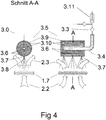
- the water supply 3.1 can also consist of a pump cylinder 3.11, which is cyclically actuated and a metered amount of water to the evaporation module 3.5 supplies (see also Fig. 4 ).
- FIG. 2 shows a longitudinal section along the cylinder axes and Fig. 3 a corresponding cross section through the cleaning device 3.0.
- the Stirling engine 1.0 includes two cylinders 1.3 and 1.4, in each of which a piston is guided.
- the pistons are mechanically coupled to the crankshaft 1.2 so that the linear motion of the pistons is converted into rotational motion of the crankshaft.
- the pistons move linearly along the cylinder axes, which are approximately parallel in the present example (which need not necessarily be the case).
- the cylinder 1.3 is “hot” and the cylinder 1.4 is “cold”, wherein the cold cylinder 1.3 lags the hot by a certain phase angle (based on the rotation angle of the crankshaft 1.2).
- the crankshaft 1.2 is arranged in a housing, the crankcase 1.1.
- a regenerator 1.6 is arranged at the cylinder end of the cold cylinder 1.4.
- the high-temperature heat exchanger 1.7 (heater) is arranged, which comes into operation during operation with the hot fuel gas 2.2 (eg over 1000 ° C.) and thus by deposits of dust, ash and other particles , which carries the fuel gas 2.2 with it, is charged.
- the heating gas 2.2 gives heat to the heat exchanger 1.7, thereby cooling to e.g. around 700 ° C.
- the cooled, but still warm fuel gas is designated by the reference numeral 2.3.
- Around the heat exchanger 1.7 around a heating gas 2.1 is arranged, which ensures that the heating gas flows through the heat exchanger 1.7.
- the operation of a Stirling machine in alpha configuration is known per se and will not be explained further here.
- the heater or heat exchanger 1.7 extends arcuately (approximately semicircular in longitudinal section Fig. 2 ) between the two cylinders 1.3 and 1.4, and consists of several channels, which are traversed by the process gas of the Stirling engine. Other than arcuate compounds may be advantageous in specific applications, but do not affect the idea of the invention.
- the cleaning device 3.0 is arranged in the immediate vicinity of the heat exchanger 1.7, that it is flowed around by the warm (cooled to eg about 700 ° C.) heating gas and heated. In operation, therefore, the cleaning device 3.0 has approximately the same temperature as the warm fuel gas 2.3.
- the heat exchanger 1.7 extends arcuately in such a way that at least partially surrounds the cleaning direction 3.0.
- the longitudinal axis of the cleaning device 3.0 is approximately in the center of the arc.
- FIG. 4 shows the same example Fig. 1 with an alternative water supply instead of a pressure port of the check valve 3.3 is preceded by a pump cylinder 3.11.
- the solenoid valve 3.2 can be omitted in this case.
- the evaporation module 3.5 Upon actuation of the pump cylinder 3.11 the evaporation module 3.5 a defined amount of liquid via the check valve 3.3 is supplied. This defined amount of liquid depends directly on the geometry (cross-sectional area and stroke) of the pumping cylinder 3.11, which can be matched to the evaporation module 3.5.
- the cleaning process may be cyclically controlled (for example, time dependent or depending on the degree of fouling of the heat exchanger), with the pump cylinder being operated once in each cycle to inject the defined amount of liquid into the evaporation module 3.5.
- Fig. 4 identical with Fig. 1 ,
Landscapes
- Engineering & Computer Science (AREA)
- Chemical & Material Sciences (AREA)
- Combustion & Propulsion (AREA)
- Mechanical Engineering (AREA)
- General Engineering & Computer Science (AREA)
- Cleaning By Liquid Or Steam (AREA)
- Cleaning Or Drying Semiconductors (AREA)
Claims (11)
- Dispositif de nettoyage d'un échangeur de chaleur (1.7), comprenant :un module d'évaporation (3.5) disposé à proximité de l'échangeur de chaleur (1.7), si bien qu'il est soumis au même flux gazeux que l'échangeur de chaleur (1.7) ;un équipement d'alimentation en eau (3.1) adapté de manière à guider une certaine quantité de liquide dans le module d'évaporation (3.5) via une conduite d'alimentation (3.4), la conduite d'alimentation (3.4) reliant l'équipement d'alimentation en eau (3.1) au module d'évaporation (3.5),caractérisé en ce quele module d'évaporation (3.5) comporte un boîtier (3.9), dans lequel est disposé un matériau (3.10) à haute capacité thermique, dans lequel sont disposés des canaux (3.6),dans lequel les canaux (3.6) affluent dans des buses de sortie (3.7), qui sont dirigées vers l'échangeur de chaleur (1.7), si bien que de la vapeur, qui est produite dans le module d'évaporation (3.5) par vaporisation du liquide dans les canaux (3.6), peut s'échapper à travers les buses de sortie (3.7) en direction de l'échangeur de chaleur (1.7).
- Dispositif selon la revendication 1,
dans lequel un clapet anti-retour (3.3) est disposé dans la conduite d'alimentation (3.4). - Dispositif selon la revendication 2,
dans lequel une soupape magnétique (3.2) à commande électrique est disposée dans la conduite d'alimentation (3.4) en série avec le clapet de non-retour (3.3). - Dispositif selon l'une des revendications 1 ou 2,
dans lequel la conduite d'alimentation (3.4) est reliée à un cylindre de pompe (3.11) de l'équipement d'alimentation en eau (3.1). - Dispositif selon l'une des revendications 1 à 4,
dans lequel le dispositif de nettoyage (3.0) est monté de façon déplaçable ou pivotante. - Dispositif selon l'une des revendications 3 ou 4, comprenant en outre :un entraînement mécanique adapté pour tourner ou déplacer progressivement le module d'évaporation (3.5),dans lequel l'entraînement mécanique et la soupape magnétique (3.2) sont contrôlés de telle manière qu'à chaque étape pendant laquelle le module d'évaporation (3.5) est tourné ou déplacé une quantité définie de liquide est amenée au module d'évaporation (3.5).
- Moteur Stirling, comprenant en outre :un échangeur de chaleur (1.7) qui est traversé par une gaz de chauffage (2.2) chaud, si bien que le gaz chauffant (2.2) délivre de la chaleur à l'échangeur de chaleur (1.7),un dispositif de nettoyage (3.0) selon l'une des revendications 1 à 5.
- Moteur Stirling selon la revendication 7, dans lequel le dispositif de nettoyage (3.0) est disposé à côté de l'échangeur de chaleur (1.7), de manière à ce que le gaz chauffant (2.2) traverse d'abord l'échangeur de chaleur (1,7) et ensuite le dispositif de nettoyage (3.0).
- Moteur Stirling selon l'une des revendications 7 ou 8, comprenant en outre :deux cylindres (1.3, 1.4), dans lequel l'échangeur de chaleur (1.7) est disposé en forme d'arc entre les deux cylindres (1.3, 1.4),dans lequel le dispositif de nettoyage (3.0) est disposé de manière à ce que l'échangeur de chaleur (1.7) l'entoure au moins en partie.
- Moteur Stirling selon l'une des revendications 7 ou 8, comprenant en outre :deux cylindres (1.3, 1.4), dans lequel l'échangeur de chaleur (1.7) est disposé autour d'un point central en forme d'arc entre les deux cylindres (1.3, 1.4),dans lequel le dispositif de nettoyage (3.0) est disposé de manière à ce son axe longitudinal passe par le point central.
- Procédé de nettoyage d'un échangeur de chaleur (1.7) ayant un module d'évaporation (3.5) disposé à proximité de l'échangeur de chaleur (1.7), si bien qu'il est soumis au même flux gazeux que l'échangeur de chaleur (1.7) ; le procédé comprend:
l'alimentation du module d'évaporation (3.5) avec une quantité de liquide définie via une conduite d'alimentation (3.4), dans lequel le liquide s'évapore dans le module d'évaporation (3.5) et de la vapeur passe vers des buses de sortie (3.7) du module d'évaporation (3.5) via des canaux (3.6) qui passent dans un matériau à haute capacité thermique à l'intérieur d'un boîtier (3.9) du module d'évaporation (3.5) et s'échappe en direction de l'échangeur de chaleur (1.7).
Applications Claiming Priority (1)
| Application Number | Priority Date | Filing Date | Title |
|---|---|---|---|
| DE102015120801.6A DE102015120801B3 (de) | 2015-12-01 | 2015-12-01 | Stirling-Motor mit einem Wärmetauscher und Verfahren zur Reinigung eines Wärmetauschers in einem Stirling-Motor |
Publications (3)
| Publication Number | Publication Date |
|---|---|
| EP3176534A2 EP3176534A2 (fr) | 2017-06-07 |
| EP3176534A3 EP3176534A3 (fr) | 2017-06-14 |
| EP3176534B1 true EP3176534B1 (fr) | 2019-05-01 |
Family
ID=57471673
Family Applications (1)
| Application Number | Title | Priority Date | Filing Date |
|---|---|---|---|
| EP16201397.3A Active EP3176534B1 (fr) | 2015-12-01 | 2016-11-30 | Dispositif et procédé de nettoyage d'un échangeur de chaleur |
Country Status (2)
| Country | Link |
|---|---|
| EP (1) | EP3176534B1 (fr) |
| DE (1) | DE102015120801B3 (fr) |
Family Cites Families (8)
| Publication number | Priority date | Publication date | Assignee | Title |
|---|---|---|---|---|
| US2115885A (en) * | 1935-06-11 | 1938-05-03 | Simpson John William Leslie | Soot blowing and cleaning apparatus for boilers, economizers, or the like |
| DD33945A1 (de) * | 1964-01-16 | 1964-11-25 | Heinz Siebeck | Sonde zur Reinigung von Dampferzeugern |
| DE102005004007B4 (de) * | 2005-01-27 | 2007-08-30 | Isenmann, Hermann, Dipl.-Ing. (FH) | Reinigung des Brennraums einer Wärmekraftmaschine, insbesondere eines Stirlingmotors |
| AT504666B1 (de) * | 2007-05-03 | 2008-07-15 | Frauscher Josef | Wärmetauscher |
| DE102008036686B4 (de) * | 2008-08-06 | 2011-03-17 | BRÜNDERMANN, Georg | Rußbläser |
| JP4650580B2 (ja) * | 2009-04-09 | 2011-03-16 | トヨタ自動車株式会社 | スターリングエンジン |
| DE102010036749A1 (de) * | 2010-07-19 | 2012-01-19 | Heizkraftwerksgesellschaft Cottbus Mbh | Verfahren zur Leistungssteigerung bei gleichzeitiger Verminderung von Ablagerungen in Kesseln mit Wirbelschicht-Feuerung |
| DE102010061072B4 (de) * | 2010-08-05 | 2015-01-15 | Qalovis Farmer Automatic Energy Gmbh | Reinigung eines mit einem Aggregat verbundenen Wärmetauschers |
-
2015
- 2015-12-01 DE DE102015120801.6A patent/DE102015120801B3/de active Active
-
2016
- 2016-11-30 EP EP16201397.3A patent/EP3176534B1/fr active Active
Non-Patent Citations (1)
| Title |
|---|
| None * |
Also Published As
| Publication number | Publication date |
|---|---|
| DE102015120801B3 (de) | 2017-03-09 |
| EP3176534A2 (fr) | 2017-06-07 |
| EP3176534A3 (fr) | 2017-06-14 |
Similar Documents
| Publication | Publication Date | Title |
|---|---|---|
| DE10054022A1 (de) | Verfahren zum Betreiben einer Wärmekraftmaschine | |
| EP0781897A2 (fr) | Méthode et dispositif pour le nettoyage humide des anneaux de tuyères de turbocompresseur | |
| EP1692450A1 (fr) | Souffleur de suie compact | |
| DE19541914A1 (de) | Kühlluftkühler für Kraftwerksanlagen | |
| EP0523466B1 (fr) | Procédé de fonctionnement d'une installation à turbines à gaz et à vapeur et installation pour la mise en oeuvre du procédé | |
| EP0308567A1 (fr) | Dispositif pour l'évaporation d'un fluide cryogénique | |
| AT504666B1 (de) | Wärmetauscher | |
| DE3406516C2 (fr) | ||
| WO1986006464A1 (fr) | Dispositif et procede pour nettoyer un echangeur de chaleur regenerateur du type a recirculation | |
| DE2725045A1 (de) | Verfahren zur reinigung eines waermetauschers | |
| DE10358233A1 (de) | Luftspeicherkraftanlage | |
| DE2630456A1 (de) | Brennkraftmaschine | |
| EP3176534B1 (fr) | Dispositif et procédé de nettoyage d'un échangeur de chaleur | |
| DE19720789B4 (de) | Verfahren und Vorrichtung zur Erzeugung von Dampf | |
| DE102008032831A1 (de) | Vorrichtung und Verfahren zur Gewinnung von mechanischer Energie aus heißen Gasströmen insbesondere eines Verbrennungsmotors | |
| DE4409338C2 (de) | Dampferzeuger | |
| DE654640C (de) | Hochleistungsdampferzeuger mit Zwangdurchlauf des Arbeitsmittels | |
| DE632897C (de) | Verfahren zur Erzeugung mechanischer Arbeit mit Hilfe der Ausdehnung von Fluessigkeiten | |
| DE102011110926A1 (de) | Reinigungsgerät für einen Konvektionsabschnitt einer Wärmekraftanlage | |
| DE102006052615B4 (de) | Einrichtung zum Bestrahlen von Reinigungsgut mit Flüssigkeit in einer Bestrahlungskammer | |
| DE102010061072B4 (de) | Reinigung eines mit einem Aggregat verbundenen Wärmetauschers | |
| DE572395C (de) | Verfahren zur Gewinnung eines Druckmittels zur Fernkraftuebertragung | |
| WO2010045925A2 (fr) | Moteur à piston avec un cylindre torique partiel et un piston torique partiel | |
| WO2013110366A2 (fr) | Dispositif d'injection d'eau pour circuit de dérivation de vapeur d'une centrale électrique | |
| DE804149C (de) | Arbeitsverfahren fuer Waermekraftanlagen und Waermekraftanlage |
Legal Events
| Date | Code | Title | Description |
|---|---|---|---|
| PUAL | Search report despatched |
Free format text: ORIGINAL CODE: 0009013 |
|
| AK | Designated contracting states |
Kind code of ref document: A2 Designated state(s): AL AT BE BG CH CY CZ DE DK EE ES FI FR GB GR HR HU IE IS IT LI LT LU LV MC MK MT NL NO PL PT RO RS SE SI SK SM TR |
|
| AX | Request for extension of the european patent |
Extension state: BA ME |
|
| AK | Designated contracting states |
Kind code of ref document: A3 Designated state(s): AL AT BE BG CH CY CZ DE DK EE ES FI FR GB GR HR HU IE IS IT LI LT LU LV MC MK MT NL NO PL PT RO RS SE SI SK SM TR |
|
| AX | Request for extension of the european patent |
Extension state: BA ME |
|
| RIC1 | Information provided on ipc code assigned before grant |
Ipc: F02G 1/055 20060101ALI20170509BHEP Ipc: F28G 1/16 20060101AFI20170509BHEP |
|
| PUAI | Public reference made under article 153(3) epc to a published international application that has entered the european phase |
Free format text: ORIGINAL CODE: 0009012 |
|
| STAA | Information on the status of an ep patent application or granted ep patent |
Free format text: STATUS: THE APPLICATION HAS BEEN PUBLISHED |
|
| STAA | Information on the status of an ep patent application or granted ep patent |
Free format text: STATUS: REQUEST FOR EXAMINATION WAS MADE |
|
| 17P | Request for examination filed |
Effective date: 20171214 |
|
| RBV | Designated contracting states (corrected) |
Designated state(s): AL AT BE BG CH CY CZ DE DK EE ES FI FR GB GR HR HU IE IS IT LI LT LU LV MC MK MT NL NO PL PT RO RS SE SI SK SM TR |
|
| GRAP | Despatch of communication of intention to grant a patent |
Free format text: ORIGINAL CODE: EPIDOSNIGR1 |
|
| STAA | Information on the status of an ep patent application or granted ep patent |
Free format text: STATUS: GRANT OF PATENT IS INTENDED |
|
| INTG | Intention to grant announced |
Effective date: 20181127 |
|
| GRAS | Grant fee paid |
Free format text: ORIGINAL CODE: EPIDOSNIGR3 |
|
| GRAA | (expected) grant |
Free format text: ORIGINAL CODE: 0009210 |
|
| STAA | Information on the status of an ep patent application or granted ep patent |
Free format text: STATUS: THE PATENT HAS BEEN GRANTED |
|
| AK | Designated contracting states |
Kind code of ref document: B1 Designated state(s): AL AT BE BG CH CY CZ DE DK EE ES FI FR GB GR HR HU IE IS IT LI LT LU LV MC MK MT NL NO PL PT RO RS SE SI SK SM TR |
|
| REG | Reference to a national code |
Ref country code: GB Ref legal event code: FG4D Free format text: NOT ENGLISH |
|
| REG | Reference to a national code |
Ref country code: CH Ref legal event code: EP Ref country code: AT Ref legal event code: REF Ref document number: 1127521 Country of ref document: AT Kind code of ref document: T Effective date: 20190515 |
|
| REG | Reference to a national code |
Ref country code: DE Ref legal event code: R096 Ref document number: 502016004409 Country of ref document: DE |
|
| REG | Reference to a national code |
Ref country code: IE Ref legal event code: FG4D Free format text: LANGUAGE OF EP DOCUMENT: GERMAN |
|
| REG | Reference to a national code |
Ref country code: NL Ref legal event code: MP Effective date: 20190501 |
|
| REG | Reference to a national code |
Ref country code: LT Ref legal event code: MG4D |
|
| PG25 | Lapsed in a contracting state [announced via postgrant information from national office to epo] |
Ref country code: FI Free format text: LAPSE BECAUSE OF FAILURE TO SUBMIT A TRANSLATION OF THE DESCRIPTION OR TO PAY THE FEE WITHIN THE PRESCRIBED TIME-LIMIT Effective date: 20190501 Ref country code: AL Free format text: LAPSE BECAUSE OF FAILURE TO SUBMIT A TRANSLATION OF THE DESCRIPTION OR TO PAY THE FEE WITHIN THE PRESCRIBED TIME-LIMIT Effective date: 20190501 Ref country code: SE Free format text: LAPSE BECAUSE OF FAILURE TO SUBMIT A TRANSLATION OF THE DESCRIPTION OR TO PAY THE FEE WITHIN THE PRESCRIBED TIME-LIMIT Effective date: 20190501 Ref country code: NO Free format text: LAPSE BECAUSE OF FAILURE TO SUBMIT A TRANSLATION OF THE DESCRIPTION OR TO PAY THE FEE WITHIN THE PRESCRIBED TIME-LIMIT Effective date: 20190801 Ref country code: PT Free format text: LAPSE BECAUSE OF FAILURE TO SUBMIT A TRANSLATION OF THE DESCRIPTION OR TO PAY THE FEE WITHIN THE PRESCRIBED TIME-LIMIT Effective date: 20190901 Ref country code: LT Free format text: LAPSE BECAUSE OF FAILURE TO SUBMIT A TRANSLATION OF THE DESCRIPTION OR TO PAY THE FEE WITHIN THE PRESCRIBED TIME-LIMIT Effective date: 20190501 Ref country code: HR Free format text: LAPSE BECAUSE OF FAILURE TO SUBMIT A TRANSLATION OF THE DESCRIPTION OR TO PAY THE FEE WITHIN THE PRESCRIBED TIME-LIMIT Effective date: 20190501 Ref country code: NL Free format text: LAPSE BECAUSE OF FAILURE TO SUBMIT A TRANSLATION OF THE DESCRIPTION OR TO PAY THE FEE WITHIN THE PRESCRIBED TIME-LIMIT Effective date: 20190501 |
|
| PG25 | Lapsed in a contracting state [announced via postgrant information from national office to epo] |
Ref country code: LV Free format text: LAPSE BECAUSE OF FAILURE TO SUBMIT A TRANSLATION OF THE DESCRIPTION OR TO PAY THE FEE WITHIN THE PRESCRIBED TIME-LIMIT Effective date: 20190501 Ref country code: RS Free format text: LAPSE BECAUSE OF FAILURE TO SUBMIT A TRANSLATION OF THE DESCRIPTION OR TO PAY THE FEE WITHIN THE PRESCRIBED TIME-LIMIT Effective date: 20190501 Ref country code: BG Free format text: LAPSE BECAUSE OF FAILURE TO SUBMIT A TRANSLATION OF THE DESCRIPTION OR TO PAY THE FEE WITHIN THE PRESCRIBED TIME-LIMIT Effective date: 20190801 Ref country code: GR Free format text: LAPSE BECAUSE OF FAILURE TO SUBMIT A TRANSLATION OF THE DESCRIPTION OR TO PAY THE FEE WITHIN THE PRESCRIBED TIME-LIMIT Effective date: 20190802 |
|
| PG25 | Lapsed in a contracting state [announced via postgrant information from national office to epo] |
Ref country code: IS Free format text: LAPSE BECAUSE OF FAILURE TO SUBMIT A TRANSLATION OF THE DESCRIPTION OR TO PAY THE FEE WITHIN THE PRESCRIBED TIME-LIMIT Effective date: 20190901 |
|
| PG25 | Lapsed in a contracting state [announced via postgrant information from national office to epo] |
Ref country code: DK Free format text: LAPSE BECAUSE OF FAILURE TO SUBMIT A TRANSLATION OF THE DESCRIPTION OR TO PAY THE FEE WITHIN THE PRESCRIBED TIME-LIMIT Effective date: 20190501 Ref country code: SK Free format text: LAPSE BECAUSE OF FAILURE TO SUBMIT A TRANSLATION OF THE DESCRIPTION OR TO PAY THE FEE WITHIN THE PRESCRIBED TIME-LIMIT Effective date: 20190501 Ref country code: EE Free format text: LAPSE BECAUSE OF FAILURE TO SUBMIT A TRANSLATION OF THE DESCRIPTION OR TO PAY THE FEE WITHIN THE PRESCRIBED TIME-LIMIT Effective date: 20190501 Ref country code: CZ Free format text: LAPSE BECAUSE OF FAILURE TO SUBMIT A TRANSLATION OF THE DESCRIPTION OR TO PAY THE FEE WITHIN THE PRESCRIBED TIME-LIMIT Effective date: 20190501 Ref country code: RO Free format text: LAPSE BECAUSE OF FAILURE TO SUBMIT A TRANSLATION OF THE DESCRIPTION OR TO PAY THE FEE WITHIN THE PRESCRIBED TIME-LIMIT Effective date: 20190501 |
|
| REG | Reference to a national code |
Ref country code: DE Ref legal event code: R097 Ref document number: 502016004409 Country of ref document: DE |
|
| PG25 | Lapsed in a contracting state [announced via postgrant information from national office to epo] |
Ref country code: SM Free format text: LAPSE BECAUSE OF FAILURE TO SUBMIT A TRANSLATION OF THE DESCRIPTION OR TO PAY THE FEE WITHIN THE PRESCRIBED TIME-LIMIT Effective date: 20190501 Ref country code: IT Free format text: LAPSE BECAUSE OF FAILURE TO SUBMIT A TRANSLATION OF THE DESCRIPTION OR TO PAY THE FEE WITHIN THE PRESCRIBED TIME-LIMIT Effective date: 20190501 |
|
| PLBE | No opposition filed within time limit |
Free format text: ORIGINAL CODE: 0009261 |
|
| STAA | Information on the status of an ep patent application or granted ep patent |
Free format text: STATUS: NO OPPOSITION FILED WITHIN TIME LIMIT |
|
| PG25 | Lapsed in a contracting state [announced via postgrant information from national office to epo] |
Ref country code: TR Free format text: LAPSE BECAUSE OF FAILURE TO SUBMIT A TRANSLATION OF THE DESCRIPTION OR TO PAY THE FEE WITHIN THE PRESCRIBED TIME-LIMIT Effective date: 20190501 |
|
| 26N | No opposition filed |
Effective date: 20200204 |
|
| PG25 | Lapsed in a contracting state [announced via postgrant information from national office to epo] |
Ref country code: PL Free format text: LAPSE BECAUSE OF FAILURE TO SUBMIT A TRANSLATION OF THE DESCRIPTION OR TO PAY THE FEE WITHIN THE PRESCRIBED TIME-LIMIT Effective date: 20190501 |
|
| PG25 | Lapsed in a contracting state [announced via postgrant information from national office to epo] |
Ref country code: SI Free format text: LAPSE BECAUSE OF FAILURE TO SUBMIT A TRANSLATION OF THE DESCRIPTION OR TO PAY THE FEE WITHIN THE PRESCRIBED TIME-LIMIT Effective date: 20190501 |
|
| PG25 | Lapsed in a contracting state [announced via postgrant information from national office to epo] |
Ref country code: MC Free format text: LAPSE BECAUSE OF FAILURE TO SUBMIT A TRANSLATION OF THE DESCRIPTION OR TO PAY THE FEE WITHIN THE PRESCRIBED TIME-LIMIT Effective date: 20190501 Ref country code: LU Free format text: LAPSE BECAUSE OF NON-PAYMENT OF DUE FEES Effective date: 20191130 |
|
| REG | Reference to a national code |
Ref country code: BE Ref legal event code: MM Effective date: 20191130 |
|
| PG25 | Lapsed in a contracting state [announced via postgrant information from national office to epo] |
Ref country code: FR Free format text: LAPSE BECAUSE OF NON-PAYMENT OF DUE FEES Effective date: 20191130 Ref country code: IE Free format text: LAPSE BECAUSE OF NON-PAYMENT OF DUE FEES Effective date: 20191130 Ref country code: ES Free format text: LAPSE BECAUSE OF FAILURE TO SUBMIT A TRANSLATION OF THE DESCRIPTION OR TO PAY THE FEE WITHIN THE PRESCRIBED TIME-LIMIT Effective date: 20190501 |
|
| PG25 | Lapsed in a contracting state [announced via postgrant information from national office to epo] |
Ref country code: BE Free format text: LAPSE BECAUSE OF NON-PAYMENT OF DUE FEES Effective date: 20191130 |
|
| PG25 | Lapsed in a contracting state [announced via postgrant information from national office to epo] |
Ref country code: CY Free format text: LAPSE BECAUSE OF FAILURE TO SUBMIT A TRANSLATION OF THE DESCRIPTION OR TO PAY THE FEE WITHIN THE PRESCRIBED TIME-LIMIT Effective date: 20190501 |
|
| GBPC | Gb: european patent ceased through non-payment of renewal fee |
Effective date: 20201130 |
|
| PG25 | Lapsed in a contracting state [announced via postgrant information from national office to epo] |
Ref country code: HU Free format text: LAPSE BECAUSE OF FAILURE TO SUBMIT A TRANSLATION OF THE DESCRIPTION OR TO PAY THE FEE WITHIN THE PRESCRIBED TIME-LIMIT; INVALID AB INITIO Effective date: 20161130 Ref country code: MT Free format text: LAPSE BECAUSE OF FAILURE TO SUBMIT A TRANSLATION OF THE DESCRIPTION OR TO PAY THE FEE WITHIN THE PRESCRIBED TIME-LIMIT Effective date: 20190501 |
|
| PG25 | Lapsed in a contracting state [announced via postgrant information from national office to epo] |
Ref country code: GB Free format text: LAPSE BECAUSE OF NON-PAYMENT OF DUE FEES Effective date: 20201130 |
|
| PG25 | Lapsed in a contracting state [announced via postgrant information from national office to epo] |
Ref country code: MK Free format text: LAPSE BECAUSE OF FAILURE TO SUBMIT A TRANSLATION OF THE DESCRIPTION OR TO PAY THE FEE WITHIN THE PRESCRIBED TIME-LIMIT Effective date: 20190501 |
|
| REG | Reference to a national code |
Ref country code: CH Ref legal event code: U11 Free format text: ST27 STATUS EVENT CODE: U-0-0-U10-U11 (AS PROVIDED BY THE NATIONAL OFFICE) Effective date: 20251201 |
|
| PGFP | Annual fee paid to national office [announced via postgrant information from national office to epo] |
Ref country code: AT Payment date: 20251117 Year of fee payment: 10 |
|
| PGFP | Annual fee paid to national office [announced via postgrant information from national office to epo] |
Ref country code: CH Payment date: 20251201 Year of fee payment: 10 |
|
| PGFP | Annual fee paid to national office [announced via postgrant information from national office to epo] |
Ref country code: DE Payment date: 20251218 Year of fee payment: 10 |