EP3176884A1 - Stromversorgungskabel mit integrierter gleichtaktdrossel - Google Patents
Stromversorgungskabel mit integrierter gleichtaktdrossel Download PDFInfo
- Publication number
- EP3176884A1 EP3176884A1 EP16188913.4A EP16188913A EP3176884A1 EP 3176884 A1 EP3176884 A1 EP 3176884A1 EP 16188913 A EP16188913 A EP 16188913A EP 3176884 A1 EP3176884 A1 EP 3176884A1
- Authority
- EP
- European Patent Office
- Prior art keywords
- power supply
- supply cable
- mode choke
- common mode
- operating state
- Prior art date
- Legal status (The legal status is an assumption and is not a legal conclusion. Google has not performed a legal analysis and makes no representation as to the accuracy of the status listed.)
- Granted
Links
- 238000000034 method Methods 0.000 claims description 7
- 238000010438 heat treatment Methods 0.000 claims description 6
- 230000001629 suppression Effects 0.000 claims description 6
- 238000004804 winding Methods 0.000 claims description 5
- XLYOFNOQVPJJNP-UHFFFAOYSA-N water Substances O XLYOFNOQVPJJNP-UHFFFAOYSA-N 0.000 claims description 4
- 239000004020 conductor Substances 0.000 description 6
- 230000001681 protective effect Effects 0.000 description 3
- 238000010586 diagram Methods 0.000 description 2
- 238000002955 isolation Methods 0.000 description 2
- 238000002347 injection Methods 0.000 description 1
- 239000007924 injection Substances 0.000 description 1
- 230000007935 neutral effect Effects 0.000 description 1
- 238000005476 soldering Methods 0.000 description 1
- 238000003466 welding Methods 0.000 description 1
- 229910000859 α-Fe Inorganic materials 0.000 description 1
Images

Classifications
-
- H—ELECTRICITY
- H01—ELECTRIC ELEMENTS
- H01B—CABLES; CONDUCTORS; INSULATORS; SELECTION OF MATERIALS FOR THEIR CONDUCTIVE, INSULATING OR DIELECTRIC PROPERTIES
- H01B9/00—Power cables
-
- H—ELECTRICITY
- H01—ELECTRIC ELEMENTS
- H01R—ELECTRICALLY-CONDUCTIVE CONNECTIONS; STRUCTURAL ASSOCIATIONS OF A PLURALITY OF MUTUALLY-INSULATED ELECTRICAL CONNECTING ELEMENTS; COUPLING DEVICES; CURRENT COLLECTORS
- H01R13/00—Details of coupling devices of the kinds covered by groups H01R12/70 or H01R24/00 - H01R33/00
- H01R13/66—Structural association with built-in electrical component
- H01R13/719—Structural association with built-in electrical component specially adapted for high frequency, e.g. with filters
- H01R13/7193—Structural association with built-in electrical component specially adapted for high frequency, e.g. with filters with ferrite filters
-
- H—ELECTRICITY
- H03—ELECTRONIC CIRCUITRY
- H03H—IMPEDANCE NETWORKS, e.g. RESONANT CIRCUITS; RESONATORS
- H03H7/00—Multiple-port networks comprising only passive electrical elements as network components
- H03H7/42—Networks for transforming balanced signals into unbalanced signals and vice versa, e.g. baluns
- H03H7/425—Balance-balance networks
- H03H7/427—Common-mode filters
-
- H—ELECTRICITY
- H01—ELECTRIC ELEMENTS
- H01F—MAGNETS; INDUCTANCES; TRANSFORMERS; SELECTION OF MATERIALS FOR THEIR MAGNETIC PROPERTIES
- H01F17/00—Fixed inductances of the signal type
- H01F17/04—Fixed inductances of the signal type with magnetic core
- H01F17/06—Fixed inductances of the signal type with magnetic core with core substantially closed in itself, e.g. toroid
- H01F2017/065—Core mounted around conductor to absorb noise, e.g. EMI filter
-
- H—ELECTRICITY
- H01—ELECTRIC ELEMENTS
- H01R—ELECTRICALLY-CONDUCTIVE CONNECTIONS; STRUCTURAL ASSOCIATIONS OF A PLURALITY OF MUTUALLY-INSULATED ELECTRICAL CONNECTING ELEMENTS; COUPLING DEVICES; CURRENT COLLECTORS
- H01R13/00—Details of coupling devices of the kinds covered by groups H01R12/70 or H01R24/00 - H01R33/00
- H01R13/66—Structural association with built-in electrical component
- H01R13/6608—Structural association with built-in electrical component with built-in single component
- H01R13/6633—Structural association with built-in electrical component with built-in single component with inductive component, e.g. transformer
Definitions
- the invention is based on a power supply cable with at least two wires, which are provided in at least one normal operating state to a current guide.
- the power supply cable has at least one integrated common mode choke.
- provided is intended to be understood in particular specially programmed, designed and / or equipped.
- the fact that an object is intended for a specific function should in particular mean that the object fulfills and / or executes this specific function in at least one application and / or operating state.
- the wires are, in particular, outer conductors and / or neutral conductors.
- the power supply cable may have a larger number of wires, in particular a larger number of outer conductors.
- a “common mode choke” should be understood to mean, in particular, a throttle which has a plurality of identical windings which are intended to be flowed through in opposite directions by a working current, so that their magnetic fields cancel in the core of the throttle.
- the common mode choke has in particular a one-piece, closed ferrite core in ring shape, E-shape, frame shape or so-called D-shape, wherein the winding wires are threaded through toroidal cores or wound on bobbins.
- integral should be understood in particular to mean that the common mode choke is at least partially integral with at least one further component and / or with at least one further element of the power supply cable.
- the wires are each electrically connected to one winding of the common mode choke.
- a generic power supply cable can be provided with advantageous properties in terms of EMC suppression of electrical appliances.
- the power supply cable can advantageously be easily used for power supply and suppression of electrical appliances that do not meet the EMC guidelines.
- the power supply cable has at least one further wire, which is provided in the normal operating state at least substantially de-energized and in at least one fault operating state to an at least temporary power supply.
- the further wire is arranged electrically separated from the common mode choke.
- the further wire can be designed as a protective conductor. In this way, advantageously, a power supply cable for use with electrical appliances, which provide a protective conductor, are provided.
- the power supply cable has at least one housing, in particular a plastic housing, which at least substantially completely encloses the common mode choke.
- the housing is formed as a Umspritzgeplouse. This can be an advantageous mechanical protection and / or advantageous electrical isolation of the common mode choke can be achieved.
- an electrical appliance with a power supply cable which has at least two cores, which are provided in at least one normal operating state to a current guide, and at least one integrated common mode choke proposed.
- a heating device in particular a hot water tank, with at least one electric device is proposed, which has a power supply cable with at least two wires, which are provided in at least a normal operating state to a current guide, and having at least one integrated common mode choke.
- the electrical appliance is designed as a circulation pump.
- a heating device should be understood as meaning, in particular, a permanently installed device for generating and / or at least temporary storage of hot water.
- a method for suppressing interference of an electrical appliance, in particular a circulation pump is proposed, wherein the electrical appliance is suppressed by means of a common mode choke integrated in a power supply cable.
- the power supply cable can advantageously be easily used for power supply and suppression of electrical appliances that do not meet the EMC guidelines.
- the power supply cable according to the invention should not be limited to the application and embodiment described above.
- the power supply cable according to the invention may have a number deviating from a number of individual elements, components and units specified herein for fulfilling a mode of operation described herein.
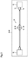
- FIG. 1 shows a power cable 10 with two wires 12, 14, which are provided in at least a normal operating state to a current guide.
- the power supply cable 10 has an integrated common mode choke 16.
- the common mode choke 16 is intended to at least reduce common mode noise that occurs.
- the cores 12, 14 are each electrically conductively connected to a respective winding 18, 20 of the common mode choke 16.
- the power supply cable 10 may have a further wire, not shown here, which is provided in the normal operating state at least substantially de-energized and in at least one fault operating state to an at least temporary power supply.
- the further wire can be designed as a protective conductor.
- the further wire is arranged electrically separated from the common mode choke 16.
- the power supply cable 10 has a housing 22 which completely encloses the common mode choke 16.
- the housing 22 is provided for mechanical protection and electrical isolation of the common mode choke 16.
- the housing 22 is formed as a Umspritzgephaseuse.
- FIG. 2 shows a simplified block diagram of an electrical system 28.
- the electrical system 28 includes an electrical device 24 with a power cable 10 according to FIG. 1 ,
- the power supply cable 10 is provided to supply electric power to the electric appliance 24.
- the electrical system 28 is designed, for example, as a heating device 26, in particular as a hot water storage.
- the electrical appliance 24 is designed, for example, as a circulation pump.
- the heating device 26 furthermore has a control unit 30, which is provided to provide a power supply of the electrical appliance 24.
- the electrical appliance 24 is connected to the control unit 30 by means of the power supply cable 10.
Landscapes
- Emergency Protection Circuit Devices (AREA)
- General Induction Heating (AREA)
Abstract
Description
- Es ist bereits ein Stromversorgungskabel mit zumindest zwei Adern, welche in zumindest einem Normalbetriebszustand zu einer Stromführung vorgesehen sind, vorgeschlagen worden.
- Die Erfindung geht aus von einem Stromversorgungskabel mit zumindest zwei Adern, welche in zumindest einem Normalbetriebszustand zu einer Stromführung vorgesehen sind.
- Es wird vorgeschlagen, dass das Stromversorgungskabel zumindest eine integrierte Gleichtaktdrossel aufweist. Unter "vorgesehen" soll insbesondere speziell programmiert, ausgelegt und/oder ausgestattet verstanden werden. Darunter, dass ein Objekt zu einer bestimmten Funktion vorgesehen ist, soll insbesondere verstanden werden, dass das Objekt diese bestimmte Funktion in zumindest einem Anwendungs- und/oder Betriebszustand erfüllt und/oder ausführt. Bei den Adern handelt es sich insbesondere um Außenleiter und/oder Neutralleiter. Insbesondere kann das Stromversorgungskabel eine größere Anzahl von Adern, insbesondere eine größere Anzahl von Außenleitern, aufweisen.
- Unter einer "Gleichtaktdrossel" soll insbesondere eine Drossel verstanden werden, welche eine Mehrzahl gleicher Wicklungen aufweist, welche dazu vorgesehen sind, gegensinnig von einem Arbeitsstrom durchflossen zu werden, sodass sich deren magnetische Felder im Kern der Drossel aufheben. Die Gleichtaktdrossel weist insbesondere einen einteiligen, geschlossenen Ferritkern in Ringform, E-Form, Rahmenform oder sogenannter D-Form auf, wobei die Wicklungsdrähte bei Ringkernen hindurchgefädelt oder auf Spulenkörpern aufgewickelt sind. Ferner soll unter "integriert" insbesondere verstanden werden, dass die Gleichtaktdrossel zumindest teilweise einstückig mit zumindest einer weiteren Komponente und/oder mit zumindest einem weiteren Element des Stromversorgungskabels ausgeführt ist. Unter "einstückig" soll insbesondere zumindest stoffschlüssig verbunden verstanden werden, beispielsweise durch einen Schweißprozess, einen Lötprozess, einen Klebeprozess, einen Anspritzprozess und/oder einen anderen, dem Fachmann als sinnvoll erscheinenden Prozess. Vorzugsweise sind die Adern jeweils elektrisch leitend mit jeweils einer Wicklung der Gleichtaktdrossel verbunden.
- Durch eine derartige Ausgestaltung kann ein gattungsgemäßes Stromversorgungskabel mit vorteilhaften Eigenschaften hinsichtlich einer EMV-Entstörung von Elektrogeräten bereitgestellt werden. Insbesondere kann das Stromversorgungskabel vorteilhaft einfach zu einer Stromversorgung und Entstörung von Elektrogeräten verwendet werden, welche nicht den EMV-Richtlinien entsprechen.
- Des Weiteren wird vorgeschlagen, dass das Stromversorgungskabel zumindest eine weitere Ader aufweist, welche im Normalbetriebszustand zumindest im Wesentlichen stromlos und in zumindest einem Fehlerbetriebszustand zu einer zumindest zeitweisen Stromführung vorgesehen ist. Vorzugsweise ist die weitere Ader elektrisch von der Gleichtaktdrossel getrennt angeordnet. Insbesondere kann die weitere Ader als ein Schutzleiter ausgebildet sein. Hierdurch kann vorteilhaft ein Stromversorgungskabel für die Verwendung mit Elektrogeräten, welche einen Schutzleiter vorsehen, bereitgestellt werden.
- Ferner wird vorgeschlagen, dass das Stromversorgungskabel zumindest ein Gehäuse, insbesondere ein Kunststoffgehäuse aufweist, welches die Gleichtaktdrossel zumindest im Wesentlichen vollständig umschließt. Vorzugsweise ist das Gehäuse als ein Umspritzgehäuse ausgebildet. Hierdurch können ein vorteilhafter mechanischer Schutz und/oder eine vorteilhafte elektrische Isolierung der Gleichtaktdrossel erreicht werden.
- Zudem wird ein Elektrogerät mit einem Stromversorgungskabel, welches zumindest zwei Adern, die in zumindest einem Normalbetriebszustand zu einer Stromführung vorgesehen sind, und zumindest einer integrierte Gleichtaktdrossel aufweist, vorgeschlagen. Hierdurch kann eine vorteilhaft einfache und/oder kostengünstige Entstörung des Elektrogeräts erreicht werden.
- Des Weiteren wird eine Heizvorrichtung, insbesondere ein Warmwasserspeicher, mit zumindest einem Elektrogerät vorgeschlagen, welches ein Stromversorgungskabel mit zumindest zwei Adern, die in zumindest einem Normalbetriebszustand zu einer Stromführung vorgesehen sind, und mit zumindest einer integrierte Gleichtaktdrossel aufweist. Vorzugsweise ist das Elektrogerät als eine Zirkulationspumpe ausgebildet. Unter einer Heizvorrichtung soll in diesem Zusammenhang insbesondere eine fest installierte Vorrichtung zur Erzeugung und/ oder zumindest temporären Speicherung von Warmwasser verstanden werden. Hierdurch kann eine vorteilhaft einfache und/oder kostengünstige Entstörung der Heizgerätevorrichtung erreicht werden
- Ferner wird ein Verfahren zur Entstörung eines Elektrogeräts, insbesondere einer Zirkulationspumpe vorgeschlagen, wobei das Elektrogerät mittels einer in einem Stromversorgungskabel integrierten Gleichtaktdrossel entstört wird. Insbesondere kann das Stromversorgungskabel vorteilhaft einfach zu einer Stromversorgung und Entstörung von Elektrogeräten verwendet werden, welche nicht den EMV-Richtlinien entsprechen.
- Das erfindungsgemäße Stromversorgungskabel soll hierbei nicht auf die oben beschriebene Anwendung und Ausführungsform beschränkt sein. Insbesondere kann das erfindungsgemäße Stromversorgungskabel zu einer Erfüllung einer hierin beschriebenen Funktionsweise eine von einer hierin genannten Anzahl von einzelnen Elementen, Bauteilen und Einheiten abweichende Anzahl aufweisen.
- Weitere Vorteile ergeben sich aus der folgenden Zeichnungsbeschreibung. In der Zeichnung ist ein Ausführungsbeispiel der Erfindung dargestellt. Die Zeichnung, die Beschreibung und die Ansprüche enthalten zahlreiche Merkmale in Kombination. Der Fachmann wird die Merkmale zweckmäßigerweise auch einzeln betrachten und zu sinnvollen weiteren Kombinationen zusammenfassen.
- Es zeigen:
- Fig. 1
- ein Stromversorgungskabel mit integrierter Gleichtaktdrossel und,
- Fig. 2
- ein vereinfachtes Blockschaltbild eines elektrischen Systems, welches ein Elektrogerät mit einem Stromversorgungskabel gemäß
Figur 1 umfasst. -
Figur 1 zeigt ein Stromversorgungskabel 10 mit zwei Adern 12, 14, welche in zumindest einem Normalbetriebszustand zu einer Stromführung vorgesehen sind. Das Stromversorgungskabel 10 weist eine integrierte Gleichtaktdrossel 16 auf. Die Gleichtaktdrossel 16 ist dazu vorgesehen, auftretende Gleichtaktstörungen zumindest zu vermindern. Die Adern 12, 14 sind jeweils elektrisch leitend mit jeweils einer Wicklung 18, 20 der Gleichtaktdrossel 16 verbunden. - Zusätzlich kann das Stromversorgungskabel 10 eine hier nicht gezeigte weitere Ader aufweisen, welche im Normalbetriebszustand zumindest im Wesentlichen stromlos und in zumindest einem Fehlerbetriebszustand zu einer zumindest zeitweisen Stromführung vorgesehen ist. Insbesondere kann die weitere Ader als ein Schutzleiter ausgebildet sein. Die weitere Ader ist elektrisch von der Gleichtaktdrossel 16 getrennt angeordnet.
- Das Stromversorgungskabel 10 weist ein Gehäuse 22 auf, welches die Gleichtaktdrossel 16 vollständig umschließt. Das Gehäuse 22 ist zu einem mechanischen Schutz und zu einer elektrischen Isolierung der Gleichtaktdrossel 16 vorgesehen. Vorzugsweise ist das Gehäuse 22 als ein Umspritzgehäuse ausgebildet.
-
Figur 2 zeigt ein vereinfachtes Blockschaltbild eines elektrischen Systems 28. Das elektrische System 28 umfasst ein Elektrogerät 24 mit einem Stromversorgungskabel 10 gemäßFigur 1 . Das Stromversorgungskabel 10 ist dazu vorgesehen, dem Elektrogerät 24 elektrische Energie zuzuführen. - Das elektrische System 28 ist beispielsweise als eine Heizvorrichtung 26, insbesondere als ein Warmwasserspeicher, ausgebildet. Das Elektrogerät 24 ist beispielsweise als eine Zirkulationspumpe ausgebildet. Die Heizvorrichtung 26 weist ferner ein Steuergerät 30 auf, welches dazu vorgesehen ist, eine Stromversorgung des Elektrogeräts 24 bereitzustellen. Das Elektrogerät 24 ist mittels des Stromversorgungskabels 10 mit dem Steuergerät 30 verbunden.
Claims (10)
- Stromversorgungskabel mit zumindest zwei Adern (12, 14), welche in zumindest einem Normalbetriebszustand zu einer Stromführung vorgesehen sind, gekennzeichnet durch zumindest eine integrierte Gleichtaktdrossel (16).
- Stromversorgungskabel nach Anspruch 1, dadurch gekennzeichnet, dass die Adern (12, 14) jeweils elektrisch leitend mit jeweils einer Wicklung (18, 20) der Gleichtaktdrossel (16) verbunden sind.
- Stromversorgungskabel nach Anspruch 1 oder 2, gekennzeichnet durch zumindest eine weitere Ader, welche im Normalbetriebszustand zumindest im Wesentlichen stromlos und in zumindest einem Fehlerbetriebszustand zu einer zumindest zeitweisen Stromführung vorgesehen ist.
- Stromversorgungskabel nach Anspruch 3, dadurch gekennzeichnet, dass die weitere Ader elektrisch von der Gleichtaktdrossel (16) getrennt angeordnet ist.
- Stromversorgungskabel nach einem der vorhergehenden Ansprüche gekennzeichnet durch zumindest ein Gehäuse (22), welches die Gleichtaktdrossel (16) zumindest im Wesentlichen vollständig umschließt.
- Stromversorgungskabel nach Anspruch 5, dadurch gekennzeichnet, dass das Gehäuse (22) als ein Umspritzgehäuse ausgebildet ist.
- Elektrogerät mit einem Stromversorgungskabel (10) nach einem der vorhergehenden Ansprüche.
- Heizvorrichtung, insbesondere Warmwasserspeicher, mit zumindest einem Elektrogerät (24) nach Anspruch 7.
- Heizvorrichtung nach Anspruch 8, dadurch gekennzeichnet, dass das Elektrogerät (24) als eine Zirkulationspumpe ausgebildet ist.
- Verfahren zur Entstörung eines Elektrogeräts (24), insbesondere einer Zirkulationspumpe, dadurch gekennzeichnet dass das Elektrogerät (24) mittels einer in einem Stromversorgungskabel (10) integrierten Gleichtaktdrossel (16) entstört wird.
Applications Claiming Priority (1)
| Application Number | Priority Date | Filing Date | Title |
|---|---|---|---|
| PT108993A PT108993A (pt) | 2015-11-30 | 2015-11-30 | Cabo de alimentação de energia elétrica com indutor de modo comum integrado |
Publications (2)
| Publication Number | Publication Date |
|---|---|
| EP3176884A1 true EP3176884A1 (de) | 2017-06-07 |
| EP3176884B1 EP3176884B1 (de) | 2019-05-29 |
Family
ID=57144738
Family Applications (1)
| Application Number | Title | Priority Date | Filing Date |
|---|---|---|---|
| EP16188913.4A Not-in-force EP3176884B1 (de) | 2015-11-30 | 2016-09-15 | Stromversorgungskabel mit integrierter gleichtaktdrossel |
Country Status (2)
| Country | Link |
|---|---|
| EP (1) | EP3176884B1 (de) |
| PT (2) | PT108993A (de) |
Cited By (2)
| Publication number | Priority date | Publication date | Assignee | Title |
|---|---|---|---|---|
| EP3676175A4 (de) * | 2017-08-30 | 2021-06-02 | Applied Signals Intelligence, Inc. | Hochfrequenzverschleiertes angebundenes flugzeug |
| WO2023186323A1 (en) * | 2022-04-01 | 2023-10-05 | HELLA GmbH & Co. KGaA | Electronic control unit for use in an electric power steering system of a vehicle |
Families Citing this family (1)
| Publication number | Priority date | Publication date | Assignee | Title |
|---|---|---|---|---|
| CN218386910U (zh) | 2019-11-25 | 2023-01-24 | 米沃奇电动工具公司 | 电池组充电系统 |
Citations (3)
| Publication number | Priority date | Publication date | Assignee | Title |
|---|---|---|---|---|
| DE102006012518A1 (de) * | 2006-03-18 | 2007-09-20 | Adc Gmbh | Steckverbinder für die Telekommunikations- und Datentechnik |
| US20130162370A1 (en) * | 2011-12-22 | 2013-06-27 | Rixin Lai | Systems and methods for providing an electric choke |
| DE202014005631U1 (de) * | 2014-07-10 | 2014-07-28 | Albert Chow | Pflanzenbeleuchtungsvorrichtung |
Family Cites Families (1)
| Publication number | Priority date | Publication date | Assignee | Title |
|---|---|---|---|---|
| DE2916403A1 (de) * | 1979-04-23 | 1980-11-06 | Basf Ag | Nadelfoermiges magnetisches eisenoxid und verfahren zu seiner herstellung |
-
2015
- 2015-11-30 PT PT108993A patent/PT108993A/pt unknown
-
2016
- 2016-09-15 EP EP16188913.4A patent/EP3176884B1/de not_active Not-in-force
- 2016-09-15 PT PT16188913T patent/PT3176884T/pt unknown
Patent Citations (3)
| Publication number | Priority date | Publication date | Assignee | Title |
|---|---|---|---|---|
| DE102006012518A1 (de) * | 2006-03-18 | 2007-09-20 | Adc Gmbh | Steckverbinder für die Telekommunikations- und Datentechnik |
| US20130162370A1 (en) * | 2011-12-22 | 2013-06-27 | Rixin Lai | Systems and methods for providing an electric choke |
| DE202014005631U1 (de) * | 2014-07-10 | 2014-07-28 | Albert Chow | Pflanzenbeleuchtungsvorrichtung |
Cited By (2)
| Publication number | Priority date | Publication date | Assignee | Title |
|---|---|---|---|---|
| EP3676175A4 (de) * | 2017-08-30 | 2021-06-02 | Applied Signals Intelligence, Inc. | Hochfrequenzverschleiertes angebundenes flugzeug |
| WO2023186323A1 (en) * | 2022-04-01 | 2023-10-05 | HELLA GmbH & Co. KGaA | Electronic control unit for use in an electric power steering system of a vehicle |
Also Published As
| Publication number | Publication date |
|---|---|
| PT108993A (pt) | 2017-05-30 |
| EP3176884B1 (de) | 2019-05-29 |
| PT3176884T (pt) | 2019-07-15 |
Similar Documents
| Publication | Publication Date | Title |
|---|---|---|
| DE102017203323B4 (de) | Fixierungsaufbau für einen abgeschirmten Steckverbinder | |
| DE102010004879A1 (de) | PMDC-Motor | |
| DE102017009352A1 (de) | Energiekoppler zum elektrischen Koppeln von elektrischen Bordnetzen und Verfahren zum elektrischen Koppeln von elektrischen Bordnetzen | |
| EP3176884B1 (de) | Stromversorgungskabel mit integrierter gleichtaktdrossel | |
| DE102017206187A1 (de) | Motor mit Verdrahtungsplatte, die durch Verbinden einer Wicklung durch Crimpen ausgebildet wird | |
| DE112015006677T5 (de) | Leitung mit Rauschfilter | |
| WO2019154685A1 (de) | Elektrische antriebseinheit für ein kraftfahrzeug | |
| DE102014213025A1 (de) | Spule für eine elektrischen Maschine | |
| WO2016050408A1 (de) | Elektrische verbindungseinrichtung zum übertragen von elektrischer energie und/oder daten, bordnetz und kraftfahrzeug | |
| DE102017206447A1 (de) | Anordnung mit Leitungsverbinder | |
| DE1763105A1 (de) | Einrichtung zur Geschwindigkeitsregelung fuer elektrische Motoren | |
| DE102018215769B4 (de) | Fahrzeugbordnetz mit einem Energiespeicher und Ladeanschlüssen | |
| DE102017221025A1 (de) | Verbindungsmittel zur elektrischen Verbindung elektrischer Leitungen | |
| WO2020165326A1 (de) | Vorrichtung zur unterdrückung von emv-gleichtaktstörungen in kfz-hochvoltanwendungen | |
| DE202010009961U1 (de) | Elektromotor | |
| DE102019112060A1 (de) | Elektrofahrzeug | |
| EP0050091A1 (de) | Wicklung für elektrische Maschinen oder Apparate | |
| DE102019008315A1 (de) | Strombegrenzungsvorrichtung für eine Leitungsschirmung eines elektrischen Leiters mit einem Kaltleiterelement, sowie elektrisches Bordnetz | |
| EP1436881A1 (de) | Vorrichtung mit einem entstörglied zur reduzierung einer störleistung | |
| DE102011103480A1 (de) | Entstördrossel für einen Elektromotor | |
| DE691981C (de) | perrenden Stromresonanzglied | |
| DE102017210209A1 (de) | Elektrisches Versorgungssystem sowie Stromkabel | |
| DE102014109269B4 (de) | Energieversorgungssystem für ein Kraftfahrzeug | |
| DE102017008550A1 (de) | Elektromagnet und damit betätigtes Ventil sowie Verfahren zum Betrieb des Ventils | |
| DE102017220705A1 (de) | Vorrichtung für eine elektrische Maschine |
Legal Events
| Date | Code | Title | Description |
|---|---|---|---|
| AK | Designated contracting states |
Kind code of ref document: A1 Designated state(s): AL AT BE BG CH CY CZ DE DK EE ES FI FR GB GR HR HU IE IS IT LI LT LU LV MC MK MT NL NO PL PT RO RS SE SI SK SM TR |
|
| AX | Request for extension of the european patent |
Extension state: BA ME |
|
| PUAI | Public reference made under article 153(3) epc to a published international application that has entered the european phase |
Free format text: ORIGINAL CODE: 0009012 |
|
| STAA | Information on the status of an ep patent application or granted ep patent |
Free format text: STATUS: THE APPLICATION HAS BEEN PUBLISHED |
|
| STAA | Information on the status of an ep patent application or granted ep patent |
Free format text: STATUS: REQUEST FOR EXAMINATION WAS MADE |
|
| 17P | Request for examination filed |
Effective date: 20171207 |
|
| RBV | Designated contracting states (corrected) |
Designated state(s): AL AT BE BG CH CY CZ DE DK EE ES FI FR GB GR HR HU IE IS IT LI LT LU LV MC MK MT NL NO PL PT RO RS SE SI SK SM TR |
|
| GRAP | Despatch of communication of intention to grant a patent |
Free format text: ORIGINAL CODE: EPIDOSNIGR1 |
|
| STAA | Information on the status of an ep patent application or granted ep patent |
Free format text: STATUS: GRANT OF PATENT IS INTENDED |
|
| INTG | Intention to grant announced |
Effective date: 20190107 |
|
| GRAS | Grant fee paid |
Free format text: ORIGINAL CODE: EPIDOSNIGR3 |
|
| GRAA | (expected) grant |
Free format text: ORIGINAL CODE: 0009210 |
|
| STAA | Information on the status of an ep patent application or granted ep patent |
Free format text: STATUS: THE PATENT HAS BEEN GRANTED |
|
| AK | Designated contracting states |
Kind code of ref document: B1 Designated state(s): AL AT BE BG CH CY CZ DE DK EE ES FI FR GB GR HR HU IE IS IT LI LT LU LV MC MK MT NL NO PL PT RO RS SE SI SK SM TR |
|
| REG | Reference to a national code |
Ref country code: GB Ref legal event code: FG4D Free format text: NOT ENGLISH |
|
| REG | Reference to a national code |
Ref country code: CH Ref legal event code: EP |
|
| REG | Reference to a national code |
Ref country code: AT Ref legal event code: REF Ref document number: 1138827 Country of ref document: AT Kind code of ref document: T Effective date: 20190615 |
|
| REG | Reference to a national code |
Ref country code: DE Ref legal event code: R096 Ref document number: 502016004846 Country of ref document: DE |
|
| REG | Reference to a national code |
Ref country code: IE Ref legal event code: FG4D Free format text: LANGUAGE OF EP DOCUMENT: GERMAN |
|
| REG | Reference to a national code |
Ref country code: PT Ref legal event code: SC4A Ref document number: 3176884 Country of ref document: PT Date of ref document: 20190715 Kind code of ref document: T Free format text: AVAILABILITY OF NATIONAL TRANSLATION Effective date: 20190704 |
|
| REG | Reference to a national code |
Ref country code: NL Ref legal event code: MP Effective date: 20190529 |
|
| REG | Reference to a national code |
Ref country code: LT Ref legal event code: MG4D |
|
| PG25 | Lapsed in a contracting state [announced via postgrant information from national office to epo] |
Ref country code: ES Free format text: LAPSE BECAUSE OF FAILURE TO SUBMIT A TRANSLATION OF THE DESCRIPTION OR TO PAY THE FEE WITHIN THE PRESCRIBED TIME-LIMIT Effective date: 20190529 Ref country code: AL Free format text: LAPSE BECAUSE OF FAILURE TO SUBMIT A TRANSLATION OF THE DESCRIPTION OR TO PAY THE FEE WITHIN THE PRESCRIBED TIME-LIMIT Effective date: 20190529 Ref country code: NO Free format text: LAPSE BECAUSE OF FAILURE TO SUBMIT A TRANSLATION OF THE DESCRIPTION OR TO PAY THE FEE WITHIN THE PRESCRIBED TIME-LIMIT Effective date: 20190829 Ref country code: LT Free format text: LAPSE BECAUSE OF FAILURE TO SUBMIT A TRANSLATION OF THE DESCRIPTION OR TO PAY THE FEE WITHIN THE PRESCRIBED TIME-LIMIT Effective date: 20190529 Ref country code: FI Free format text: LAPSE BECAUSE OF FAILURE TO SUBMIT A TRANSLATION OF THE DESCRIPTION OR TO PAY THE FEE WITHIN THE PRESCRIBED TIME-LIMIT Effective date: 20190529 Ref country code: HR Free format text: LAPSE BECAUSE OF FAILURE TO SUBMIT A TRANSLATION OF THE DESCRIPTION OR TO PAY THE FEE WITHIN THE PRESCRIBED TIME-LIMIT Effective date: 20190529 Ref country code: SE Free format text: LAPSE BECAUSE OF FAILURE TO SUBMIT A TRANSLATION OF THE DESCRIPTION OR TO PAY THE FEE WITHIN THE PRESCRIBED TIME-LIMIT Effective date: 20190529 |
|
| PG25 | Lapsed in a contracting state [announced via postgrant information from national office to epo] |
Ref country code: LV Free format text: LAPSE BECAUSE OF FAILURE TO SUBMIT A TRANSLATION OF THE DESCRIPTION OR TO PAY THE FEE WITHIN THE PRESCRIBED TIME-LIMIT Effective date: 20190529 Ref country code: GR Free format text: LAPSE BECAUSE OF FAILURE TO SUBMIT A TRANSLATION OF THE DESCRIPTION OR TO PAY THE FEE WITHIN THE PRESCRIBED TIME-LIMIT Effective date: 20190830 Ref country code: BG Free format text: LAPSE BECAUSE OF FAILURE TO SUBMIT A TRANSLATION OF THE DESCRIPTION OR TO PAY THE FEE WITHIN THE PRESCRIBED TIME-LIMIT Effective date: 20190829 Ref country code: RS Free format text: LAPSE BECAUSE OF FAILURE TO SUBMIT A TRANSLATION OF THE DESCRIPTION OR TO PAY THE FEE WITHIN THE PRESCRIBED TIME-LIMIT Effective date: 20190529 |
|
| PG25 | Lapsed in a contracting state [announced via postgrant information from national office to epo] |
Ref country code: DK Free format text: LAPSE BECAUSE OF FAILURE TO SUBMIT A TRANSLATION OF THE DESCRIPTION OR TO PAY THE FEE WITHIN THE PRESCRIBED TIME-LIMIT Effective date: 20190529 Ref country code: EE Free format text: LAPSE BECAUSE OF FAILURE TO SUBMIT A TRANSLATION OF THE DESCRIPTION OR TO PAY THE FEE WITHIN THE PRESCRIBED TIME-LIMIT Effective date: 20190529 Ref country code: CZ Free format text: LAPSE BECAUSE OF FAILURE TO SUBMIT A TRANSLATION OF THE DESCRIPTION OR TO PAY THE FEE WITHIN THE PRESCRIBED TIME-LIMIT Effective date: 20190529 Ref country code: RO Free format text: LAPSE BECAUSE OF FAILURE TO SUBMIT A TRANSLATION OF THE DESCRIPTION OR TO PAY THE FEE WITHIN THE PRESCRIBED TIME-LIMIT Effective date: 20190529 Ref country code: NL Free format text: LAPSE BECAUSE OF FAILURE TO SUBMIT A TRANSLATION OF THE DESCRIPTION OR TO PAY THE FEE WITHIN THE PRESCRIBED TIME-LIMIT Effective date: 20190529 Ref country code: SK Free format text: LAPSE BECAUSE OF FAILURE TO SUBMIT A TRANSLATION OF THE DESCRIPTION OR TO PAY THE FEE WITHIN THE PRESCRIBED TIME-LIMIT Effective date: 20190529 |
|
| PGFP | Annual fee paid to national office [announced via postgrant information from national office to epo] |
Ref country code: DE Payment date: 20191125 Year of fee payment: 4 |
|
| PG25 | Lapsed in a contracting state [announced via postgrant information from national office to epo] |
Ref country code: SM Free format text: LAPSE BECAUSE OF FAILURE TO SUBMIT A TRANSLATION OF THE DESCRIPTION OR TO PAY THE FEE WITHIN THE PRESCRIBED TIME-LIMIT Effective date: 20190529 Ref country code: IT Free format text: LAPSE BECAUSE OF FAILURE TO SUBMIT A TRANSLATION OF THE DESCRIPTION OR TO PAY THE FEE WITHIN THE PRESCRIBED TIME-LIMIT Effective date: 20190529 |
|
| REG | Reference to a national code |
Ref country code: DE Ref legal event code: R097 Ref document number: 502016004846 Country of ref document: DE |
|
| PLBE | No opposition filed within time limit |
Free format text: ORIGINAL CODE: 0009261 |
|
| STAA | Information on the status of an ep patent application or granted ep patent |
Free format text: STATUS: NO OPPOSITION FILED WITHIN TIME LIMIT |
|
| PG25 | Lapsed in a contracting state [announced via postgrant information from national office to epo] |
Ref country code: PL Free format text: LAPSE BECAUSE OF FAILURE TO SUBMIT A TRANSLATION OF THE DESCRIPTION OR TO PAY THE FEE WITHIN THE PRESCRIBED TIME-LIMIT Effective date: 20190529 |
|
| 26N | No opposition filed |
Effective date: 20200303 |
|
| PG25 | Lapsed in a contracting state [announced via postgrant information from national office to epo] |
Ref country code: MC Free format text: LAPSE BECAUSE OF FAILURE TO SUBMIT A TRANSLATION OF THE DESCRIPTION OR TO PAY THE FEE WITHIN THE PRESCRIBED TIME-LIMIT Effective date: 20190529 Ref country code: SI Free format text: LAPSE BECAUSE OF FAILURE TO SUBMIT A TRANSLATION OF THE DESCRIPTION OR TO PAY THE FEE WITHIN THE PRESCRIBED TIME-LIMIT Effective date: 20190529 |
|
| REG | Reference to a national code |
Ref country code: CH Ref legal event code: PL |
|
| PG25 | Lapsed in a contracting state [announced via postgrant information from national office to epo] |
Ref country code: LU Free format text: LAPSE BECAUSE OF NON-PAYMENT OF DUE FEES Effective date: 20190915 Ref country code: LI Free format text: LAPSE BECAUSE OF NON-PAYMENT OF DUE FEES Effective date: 20190930 Ref country code: CH Free format text: LAPSE BECAUSE OF NON-PAYMENT OF DUE FEES Effective date: 20190930 Ref country code: IE Free format text: LAPSE BECAUSE OF NON-PAYMENT OF DUE FEES Effective date: 20190915 |
|
| REG | Reference to a national code |
Ref country code: BE Ref legal event code: MM Effective date: 20190930 |
|
| PG25 | Lapsed in a contracting state [announced via postgrant information from national office to epo] |
Ref country code: BE Free format text: LAPSE BECAUSE OF NON-PAYMENT OF DUE FEES Effective date: 20190930 |
|
| PGFP | Annual fee paid to national office [announced via postgrant information from national office to epo] |
Ref country code: PT Payment date: 20200910 Year of fee payment: 5 Ref country code: FR Payment date: 20200922 Year of fee payment: 5 Ref country code: TR Payment date: 20200914 Year of fee payment: 5 |
|
| REG | Reference to a national code |
Ref country code: DE Ref legal event code: R119 Ref document number: 502016004846 Country of ref document: DE |
|
| GBPC | Gb: european patent ceased through non-payment of renewal fee |
Effective date: 20200915 |
|
| PG25 | Lapsed in a contracting state [announced via postgrant information from national office to epo] |
Ref country code: CY Free format text: LAPSE BECAUSE OF FAILURE TO SUBMIT A TRANSLATION OF THE DESCRIPTION OR TO PAY THE FEE WITHIN THE PRESCRIBED TIME-LIMIT Effective date: 20190529 |
|
| PG25 | Lapsed in a contracting state [announced via postgrant information from national office to epo] |
Ref country code: IS Free format text: LAPSE BECAUSE OF FAILURE TO SUBMIT A TRANSLATION OF THE DESCRIPTION OR TO PAY THE FEE WITHIN THE PRESCRIBED TIME-LIMIT Effective date: 20190929 |
|
| PG25 | Lapsed in a contracting state [announced via postgrant information from national office to epo] |
Ref country code: MT Free format text: LAPSE BECAUSE OF FAILURE TO SUBMIT A TRANSLATION OF THE DESCRIPTION OR TO PAY THE FEE WITHIN THE PRESCRIBED TIME-LIMIT Effective date: 20190529 Ref country code: DE Free format text: LAPSE BECAUSE OF NON-PAYMENT OF DUE FEES Effective date: 20210401 Ref country code: HU Free format text: LAPSE BECAUSE OF FAILURE TO SUBMIT A TRANSLATION OF THE DESCRIPTION OR TO PAY THE FEE WITHIN THE PRESCRIBED TIME-LIMIT; INVALID AB INITIO Effective date: 20160915 |
|
| PG25 | Lapsed in a contracting state [announced via postgrant information from national office to epo] |
Ref country code: GB Free format text: LAPSE BECAUSE OF NON-PAYMENT OF DUE FEES Effective date: 20200915 |
|
| PG25 | Lapsed in a contracting state [announced via postgrant information from national office to epo] |
Ref country code: PT Free format text: LAPSE BECAUSE OF NON-PAYMENT OF DUE FEES Effective date: 20220315 |
|
| PG25 | Lapsed in a contracting state [announced via postgrant information from national office to epo] |
Ref country code: MK Free format text: LAPSE BECAUSE OF FAILURE TO SUBMIT A TRANSLATION OF THE DESCRIPTION OR TO PAY THE FEE WITHIN THE PRESCRIBED TIME-LIMIT Effective date: 20190529 |
|
| PG25 | Lapsed in a contracting state [announced via postgrant information from national office to epo] |
Ref country code: FR Free format text: LAPSE BECAUSE OF NON-PAYMENT OF DUE FEES Effective date: 20210930 |
|
| REG | Reference to a national code |
Ref country code: AT Ref legal event code: MM01 Ref document number: 1138827 Country of ref document: AT Kind code of ref document: T Effective date: 20210915 |
|
| PG25 | Lapsed in a contracting state [announced via postgrant information from national office to epo] |
Ref country code: AT Free format text: LAPSE BECAUSE OF NON-PAYMENT OF DUE FEES Effective date: 20210915 |
|
| PG25 | Lapsed in a contracting state [announced via postgrant information from national office to epo] |
Ref country code: TR Free format text: LAPSE BECAUSE OF NON-PAYMENT OF DUE FEES Effective date: 20210915 |