EP3177437B1 - Dispositif articulé pour systèmes robotiques - Google Patents
Dispositif articulé pour systèmes robotiques Download PDFInfo
- Publication number
- EP3177437B1 EP3177437B1 EP15752979.3A EP15752979A EP3177437B1 EP 3177437 B1 EP3177437 B1 EP 3177437B1 EP 15752979 A EP15752979 A EP 15752979A EP 3177437 B1 EP3177437 B1 EP 3177437B1
- Authority
- EP
- European Patent Office
- Prior art keywords
- rigid body
- rotation axis
- rotation
- actuator
- articulated device
- Prior art date
- Legal status (The legal status is an assumption and is not a legal conclusion. Google has not performed a legal analysis and makes no representation as to the accuracy of the status listed.)
- Active
Links
Images







Classifications
-
- B—PERFORMING OPERATIONS; TRANSPORTING
- B25—HAND TOOLS; PORTABLE POWER-DRIVEN TOOLS; MANIPULATORS
- B25J—MANIPULATORS; CHAMBERS PROVIDED WITH MANIPULATION DEVICES
- B25J17/00—Joints
- B25J17/02—Wrist joints
-
- A—HUMAN NECESSITIES
- A61—MEDICAL OR VETERINARY SCIENCE; HYGIENE
- A61B—DIAGNOSIS; SURGERY; IDENTIFICATION
- A61B34/00—Computer-aided surgery; Manipulators or robots specially adapted for use in surgery
- A61B34/30—Surgical robots
-
- B—PERFORMING OPERATIONS; TRANSPORTING
- B25—HAND TOOLS; PORTABLE POWER-DRIVEN TOOLS; MANIPULATORS
- B25J—MANIPULATORS; CHAMBERS PROVIDED WITH MANIPULATION DEVICES
- B25J17/00—Joints
- B25J17/02—Wrist joints
- B25J17/0283—Three-dimensional joints
- B25J17/0291—Three-dimensional joints having axes crossing at an oblique angle, i.e. other than 90 degrees
-
- A—HUMAN NECESSITIES
- A61—MEDICAL OR VETERINARY SCIENCE; HYGIENE
- A61B—DIAGNOSIS; SURGERY; IDENTIFICATION
- A61B34/00—Computer-aided surgery; Manipulators or robots specially adapted for use in surgery
- A61B34/30—Surgical robots
- A61B2034/302—Surgical robots specifically adapted for manipulations within body cavities, e.g. within abdominal or thoracic cavities
-
- A—HUMAN NECESSITIES
- A61—MEDICAL OR VETERINARY SCIENCE; HYGIENE
- A61B—DIAGNOSIS; SURGERY; IDENTIFICATION
- A61B34/00—Computer-aided surgery; Manipulators or robots specially adapted for use in surgery
- A61B34/30—Surgical robots
- A61B2034/305—Details of wrist mechanisms at distal ends of robotic arms
-
- Y—GENERAL TAGGING OF NEW TECHNOLOGICAL DEVELOPMENTS; GENERAL TAGGING OF CROSS-SECTIONAL TECHNOLOGIES SPANNING OVER SEVERAL SECTIONS OF THE IPC; TECHNICAL SUBJECTS COVERED BY FORMER USPC CROSS-REFERENCE ART COLLECTIONS [XRACs] AND DIGESTS
- Y10—TECHNICAL SUBJECTS COVERED BY FORMER USPC
- Y10S—TECHNICAL SUBJECTS COVERED BY FORMER USPC CROSS-REFERENCE ART COLLECTIONS [XRACs] AND DIGESTS
- Y10S901/00—Robots
- Y10S901/19—Drive system for arm
- Y10S901/25—Gearing
- Y10S901/26—Gearing including bevel gear
-
- Y—GENERAL TAGGING OF NEW TECHNOLOGICAL DEVELOPMENTS; GENERAL TAGGING OF CROSS-SECTIONAL TECHNOLOGIES SPANNING OVER SEVERAL SECTIONS OF THE IPC; TECHNICAL SUBJECTS COVERED BY FORMER USPC CROSS-REFERENCE ART COLLECTIONS [XRACs] AND DIGESTS
- Y10—TECHNICAL SUBJECTS COVERED BY FORMER USPC
- Y10S—TECHNICAL SUBJECTS COVERED BY FORMER USPC CROSS-REFERENCE ART COLLECTIONS [XRACs] AND DIGESTS
- Y10S901/00—Robots
- Y10S901/27—Arm part
- Y10S901/28—Joint
- Y10S901/29—Wrist
Definitions
- the present invention relates to an articulated device for robotic systems, which is particularly adapted for use in robotic systems requiring particular dexterity, such as, for example, robotic systems operating in the field of robotic surgery and in particular in the field of minimally-invasive robotic surgery.
- the aim of the present invention is to provide an articulated device that overcomes the limitations of the background art, making it possible to achieve considerable dexterity.
- an object of the present invention is to provide a miniaturized articulated device.
- Another object of the invention is to provide an articulated device that is particularly adapted for use in robotic systems for minimally-invasive robotic surgery.
- Another object of the invention is to provide an articulated device that is capable of giving the greatest assurances of reliability and safety in use.
- Another object of the invention is to provide an articulated device that is easy to provide and economically and technically competitive when compared with the background art.
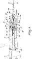
- the articulated device generally designated by the reference numeral 1, comprises:
- the first rotation axis 5, the second rotation axis 11 and the third rotation axis 15 coincide in at least one point P, which defines the center of rotation of the articulated device 1.
- the articulated device 1 advantageously provides a spherical joint.
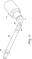
- the surface traced by the end point of the terminal element of the articulated device 1, i.e., the work space of the articulated device 1 is a spherical dome C centered in the point P of intersection of the rotation axes.
- the second rotation axis 11 is inclined with respect to the first rotation axis 5.
- the second rotation axis 11 is inclined with respect to the first rotation axis 5 by an angle comprised in the interval between 30° and 60° and even more preferably by an angle equal to approximately 45°. In the embodiment of the articulated device 1 shown in the accompanying figures, such angle is approximately equal to 35°.
- the third rotation axis 15 can coincide with the first rotation axis 5.
- the articulated device 1 can also comprise the rigid base body 7, which is configured advantageously to rotate about a fourth rotation axis 17 with respect to an additional rigid reference body, not shown in the accompanying figures.
- the articulated device 1 comprises advantageously first rotation means 19 which are adapted to rotate the first rigid body 3 with respect to the rigid base body 7, about the first rotation axis 5.
- Such first rotation means 19 comprise advantageously:
- the actuation of the first actuator 21 entails the rotation of the first rigid body 3 with respect to the rigid base body 7 about the first rotation axis 5.
- the first rotation means 19 comprise a first four-contact point bearing 27, which is interposed between the rigid base body 7 and the first rigid body 3.
- the first four-point contact bearing 27 is advantageously of the ball bearing type.
- Such bearing comprises a radially external annular element 29, which is integral with the rigid base body 7, and a radially internal annular element 31, which is integral with the first rigid body 3.
- the radially internal annular element 31 comprises two annular element halves that can face each other.
- the rigid base body 7 and the first rigid body 3 can be mutually fastened in an adjustable manner by way of the fastening and adjustment screws 28.
- the integration of the four-point contact bearing in such rotation joint makes it possible to obtain a mechanical structure that is compact, with a smaller axial and radial space occupation and therefore more space available inside the joint, using far fewer parts than alternative constructive solutions; the four-point contact bearing has a high radial and axial load capacity and high rigidity.
- an alternative solution is to use a pair of preloaded roller bearings; however, this last solution requires a higher number of parts and a greater physical space occupation.
- the integration of the four-point contact bearing in the joint is particularly advantageous for the intra-abdominal surgical robot application.
- the articulated device 1 comprises advantageously second rotation means 33 which are adapted to rotate the second rigid body 9 with respect to the first rigid body 3, about the second rotation axis 11.
- Such second rotation means 33 advantageously comprise:
- the motion transmission means 39 advantageously comprise a second pinion 45, which is rotated by the second actuator 35, and a gear 47 which engages the pinion 45 and, being integral with the first gear 41 of the gear pair 37, transmits its rotation.
- the actuation of the second actuator 35 entails the rotation of the second rigid body 9 with respect to the first rigid body 3, about the second rotation axis 11.
- the angle of inclination defined by the pair of gears 37 determines the angle of inclination of the second rotation axis 11 with respect to the first rotation axis 5.
- the second rotation means 33 comprise a second four-point contact bearing 49, which is interposed between the first rigid body 3 and the second rigid body 9.
- the second four-point contact bearing 49 is advantageously of the ball bearing type.
- Such bearing comprises a radially external annular element 51, which is integral with the second rigid body 9, and a radially internal annular element 53, which is integral with the first rigid body 3.
- the radially internal annular element 53 comprises two annular element halves which can face each other.
- the first rigid body 3 and the second rigid body 9 can be advantageously fastened adjustably with respect to each other with the interposition of the second four-point contact bearing 49, by way of a plurality of fastening and adjustment screws 55.
- the integration of the four-point contact ball bearing in such rotation joint makes it possible to obtain a mechanical structure that is compact, with a smaller axial and radial space occupation and therefore more space available inside the joint, using far fewer parts than alternative constructive solutions; the four-point contact ball bearing has a high radial and axial load capacity and high rigidity.
- an alternative solution is to use a pair of preloaded roller bearings; however, this last solution requires a higher number of parts and a greater physical space occupation.
- the integration of the four-point contact ball bearing in the joint is particularly advantageous for the intra-abdominal surgical robot application.
- the articulated device 1 advantageously comprises third rotation means 57 which are adapted to rotate the third rigid body 13 with respect to the second rigid body 9, about the third rotation axis 15.
- Such third rotation means 57 advantageously comprise:
- the flexible hollow shaft 65 is coupled rotationally to the third rigid body 13, so that the rotation imparted by the third actuator 59 is transmitted to the third rigid body 13, which consequently can rotate about the third rotation axis 15.
- the flexible hollow shaft 65 is advantageously coupled to the gear 63 by way of a first key-like end 67, which is configured to engage within such gear 63.
- the flexible hollow shaft 65 comprises advantageously a second key-like end 69, which is configured to engage within a corresponding cavity 71 provided in the third rigid body 13.
- the second key-like end 69 can have a square or rectangular transverse cross-section, and correspondingly a square or rectangular cavity 71 can be provided in the third rigid body 13.
- the flexible hollow shaft 65 is advantageously made of a flexible material, since it must be able to bend when the second rigid body 9 rotates with respect to the first rigid body 3 about the second rotation axis 11.
- the flexible hollow shaft 65 is adapted to transmit the rotation about the third rotation axis 15 to the third rigid body 13 regardless of the operating configuration assumed by the second rigid body 9.
- the second key-like end 69 is configured to be able to freely slide axially within the cavity 71 of the third rigid body 13, so that, regardless of the operating configuration assumed by the second rigid body 9, the flexible hollow shaft 65 is in any case capable of transmitting the rotation to the third rigid body 13.
- the second key-like end 69 engages in the cavity 71 only along the portion 73. If the second rigid body 9 assumes a different operating configuration, for example such as the one shown in Figure 2 , then the second key-like end 69 can slide further within the cavity 71, keeping the rotational coupling active in both cases.
- the articulated device 1 can be adopted for any type of articulation of a robotic system.
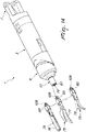
- the articulated device 1 is adopted for a terminal articulation of a robotic system, i.e., an articulation that supports, moves, and optionally actuates a terminal operating instrument 75, such as graspers 76, a dissector 77, or scissors 78.
- a terminal operating instrument 75 such as graspers 76, a dissector 77, or scissors 78.
- the articulated device 1 can comprise means 79 of fixing an operating instrument 75 to the third rigid body 13.
- the fixing means 79 comprise a threaded cavity 81 which is configured to engage a corresponding threaded portion 83 of the operating instrument 75.
- the articulated device 1 comprises means 85 of actuating the operating instrument 75.
- the actuation means 85 are adapted to allow the opening and closing of the graspers 75 or of the scissors 77.
- Such actuation means 85 advantageously comprise:
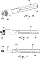
- the operating instrument 75 comprises advantageously a lever system 105, the traction and/or thrust of which entails the opening and/or closure of the graspers 76 or of the scissors 77.
- the traction and/or thrust of such lever system 105 is obtained by way of a rod 107 which has a threaded end 109.
- the third rigid body 13 in addition to comprising the fixing means 79 with the threaded cavity 81, also comprises a block 111, with a threaded cavity 112, which can slide within a cavity 113 provided in the rigid third rigid body 13, and is coupled to the second end of the flexible cable 97.
- the actuator 87 rotates the fourth pinion 89, which transmits the motion to the gear 95, which rotates about its own axis integrally with the worm gear 93. Consequently, the worm gear 93 screws into the threaded through hole 91 provided in the first rigid element 3, thus advancing or retracting along the axis of longitudinal extension of such first rigid body 3.
- the advancement of the worm gear 93, which also entrains with it the gear 95, is allowed by the fact that the gear 95 has a longitudinal extension that is such as to always be meshed with the fourth pinion 89, in any operating configuration.
- the axial movement of the worm gear 93 causes the thrust or the traction of the flexible cable 97, which produces the axial motion of the block 111 within the cavity 113 and consequently of the rod 107 connected thereto by way of the threaded end 109.
- the thrust or the traction of the threaded rod 107 actuates the lever system 105, which opens and closes the graspers 76 or the scissors 77.
- the threading of the threaded cavity 81 and the threading of the threaded cavity 112 of the block 111 have the same pitch.
- the block 111 can have a "key-like" external shape, configured to remain integral in rotation with the third rigid body 13.
- the block 111 there can be an axial hollow, configured to engage a corresponding axial lip that protrudes from the internal lateral surface of the third rigid body 13. The lip can slide axially within the hollow but is coupled rotationally thereto.
- the tool changing operation occurs by way of a single movement: by keeping the terminal operating instrument rotationally locked and turning the output shaft (rigid body 13) one achieves simultaneously the disengagement (or engagement) of the external body of the operating instrument and of the corresponding internal actuation rod 107.
- This characteristic makes the mechanism particularly adapted for the tool changing of terminal operating instruments during the surgical procedure.
- the articulated device 1 comprises an alternative embodiment of the second rotation means which are adapted to rotate the second rigid body 9 with respect to the first rigid body 3, about the second rotation axis 11, designated by the reference numeral 133.
- the second rotation means 133 comprise advantageously:
- the motion transmission means 139 advantageously comprise a second pinion 145, which is rotated by the second actuator 135, and a ring gear 147, which engages the pinion 145 and, being integral with the first end 141 of the second flexible hollow shaft 137, transmits its rotation.
- the second end 143 comprises a key-like element 151, which is configured to be accommodated in a corresponding key-like seat 153 provided in the second rigid body 9.
- the key-like element 151 inserted in the key-like seat 153 makes it possible to transmit the rotation of the second flexible hollow shaft 137 to the second rigid body 9.
- the second flexible hollow shaft 137 is advantageously made of a flexible material, since it must be able to bend when the second rigid body 9 rotates with respect to the first rigid body 3 about the second rotation axis 11.
- the second rigid body 9 faces the first rigid body 3 along a plane 150 which is inclined with respect to the first rotation axis 5. In its rotation, the second rigid body 9 is coupled so as to maintain contact with the first rigid body 3 along such inclined plane 150, and this determines the rotation of the second rigid body 9 about the second rotation axis 11, at right angles to such plane 150.
- the angle of inclination defined by such plane 150 determines the angle of inclination of the second rotation axis 11 with respect to the first rotation axis 5.
- the second flexible hollow shaft 137 can transmit the rotation to the second rigid body 9 in any operating configuration assumed by such second rigid body 9, the key-like element 151 is free to slide axially within the key-like seat 153.
- the distance between the second end 143 of the second flexible hollow shaft 137 and the third rigid body 13 varies depending on the operating configuration assumed by such second rigid body 9.
- the second flexible hollow shaft 137 is advantageously configured to contain, coaxially, the flexible hollow shaft 65 that belongs to the third rotation means 57 as described above. And likewise, the flexible hollow shaft 65 can coaxially accommodate the flexible cable 97, which belongs to the actuation means 85.
- the second rotation means 133 comprise a second four-point contact bearing 149, which is interposed between the first rigid body 3 and the second rigid body 9.
- Such second four-point contact bearing 149 is configured to ensure the sliding between the respective facing surfaces of the first rigid body 3 and of the second rigid body 9.
- the particular configuration of the rotation means 19, 33 and 57 makes it possible to actuate the articulated device 1 within a spherical dome C which has as its center of origin a point P that coincides with the center of rotation of such articulated device 1.
- additional actuation means 85 also makes it possible to actuate a terminal operating instrument 75, which can conveniently be connected to the articulated device 1.
- the articulated device achieves the intended aim and objects, since it makes it possible to achieve very high levels of dexterity.
- Another advantage of the articulated device, according to the invention consists in that it can assume miniaturized dimensions.
- a further advantage of the articulated device, according to the invention consists in that it can be adopted in robotic systems that are adapted to operate in the field of minimally-invasive robotic surgery, where work spaces are very confined and limited, and where extreme accuracy is required.
- Another advantage of the articulated device consists in that it can be adopted for any articulation of a robotic system, although it is particularly adapted for terminal articulations that operate an operating instrument.
Landscapes
- Engineering & Computer Science (AREA)
- Health & Medical Sciences (AREA)
- Robotics (AREA)
- Life Sciences & Earth Sciences (AREA)
- Surgery (AREA)
- Mechanical Engineering (AREA)
- Heart & Thoracic Surgery (AREA)
- Biomedical Technology (AREA)
- Nuclear Medicine, Radiotherapy & Molecular Imaging (AREA)
- Medical Informatics (AREA)
- Molecular Biology (AREA)
- Animal Behavior & Ethology (AREA)
- General Health & Medical Sciences (AREA)
- Public Health (AREA)
- Veterinary Medicine (AREA)
- Manipulator (AREA)
Claims (9)
- Dispositif articulé (1) pour systèmes robotiques, comportant :- un premier corps rigide (3), qui est configuré pour tourner autour d'un premier axe de rotation (5) par rapport à un corps de base rigide (7),- un deuxième corps rigide (9), qui est configuré pour tourner autour d'un deuxième axe de rotation (11) par rapport audit premier corps rigide (3),- un troisième corps rigide (13), qui est configuré pour tourner autour d'un troisième axe de rotation (15) par rapport audit deuxième corps rigide (9),
ledit premier axe de rotation (5), ledit deuxième axe de rotation (11) et ledit troisième axe de rotation (15) coïncidant en au moins un point (P), qui définit le centre de rotation dudit dispositif articulé (1) ,- des premiers moyens (19) pour la rotation dudit premier corps rigide (3) par rapport audit premier axe de rotation (5),- des deuxièmes moyens (33) pour la rotation dudit deuxième corps rigide (9) par rapport audit deuxième axe de rotation (11), et- des troisièmes moyens (57) pour la rotation dudit troisième corps rigide (13) par rapport audit troisième axe de rotation (15) ;- lesdits deuxièmes moyens de rotation (33) comportant :- un deuxième actionneur (35, 135), qui est couplé rigidement audit premier corps rigide (3),- une paire d'engrenages (37), qui comporte un premier engrenage (41) qui est mis en rotation par ledit deuxième actionneur (35), par des moyens de transmission de mouvement (39), et un second engrenage (43), qui est solidaire dudit deuxième corps rigide (9),- l'actionnement dudit deuxième actionneur (35) étant adapté pour faire tourner ledit deuxième corps rigide (9) par rapport audit premier corps rigide (3), autour dudit deuxième axe de rotation (11),caractérisé en ce que- lesdits premiers moyens de rotation (19) comportent un premier palier à quatre points de contact (27) qui est intercalé entre le corps de base rigide (7) et le premiers corps rigide (3), et en ce que- lesdits deuxièmes moyens de rotation (33) comportent un second palier à quatre points de contact (49) qui est agencé sur ledit centre de rotation (P) dudit dispositif articulé (1) et est intercalé entre le premier corps rigide (3) et le deuxième corps rigide (9), ledit second palier à quatre points de contact (49) étant agencé de sorte que le premier corps rigide (3) et le deuxième corps rigide (9) lorsqu'ils sont couplés ensemble et au repos sont agencés en ligne, ledit deuxième corps rigide (9) étant agencé dans la masse du premier corps rigide (3),- lesdits premiers moyens de rotation (19) comportant :- un premier actionneur (21), qui est couplé rigidement audit premier corps rigide (3),- un premier pignon (23), qui est mis en rotation par ledit premier actionneur (21),- une première couronne (25), qui est couplée rigidement audit corps de base rigide (7) et est adaptée pour s'engrener avec ledit premier pignon (23),- l'actionnement dudit premier actionneur (21) étant adapté pour faire tourner ledit premier corps rigide (3) par rapport audit corps de base rigide (7), autour dudit premier axe de rotation (5). - Dispositif articulé (1) selon la revendication 1, caractérisé en ce que ledit deuxième axe de rotation (11) est incliné par rapport audit premier axe de rotation (5).
- Dispositif articulé (1) selon la revendication 1 ou 2, caractérisé en ce que ledit deuxième axe de rotation (11) est incliné par rapport audit premier axe de rotation (5) d'un angle compris dans l'intervalle entre 30° et 60°.
- Dispositif articulé (1) selon la revendication 1, caractérisé en ce que lesdits deuxièmes moyens de rotation (133) comportent :- ledit deuxième actionneur (135), qui est couplé rigidement audit premier corps rigide (3),- un arbre creux souple (137), comportant une première extrémité (141), qui est mise en rotation par ledit deuxième actionneur (135) par des moyens de transmission de mouvement (139), et une seconde extrémité (143), qui tourne solidairement dudit deuxième corps rigide (9),l'actionnement dudit deuxième actionneur (135) étant adapté pour faire tourner ledit deuxième corps rigide (9) par rapport audit premier corps rigide (3), autour dudit deuxième axe de rotation (11).
- Dispositif articulé (1) selon la revendication 1, caractérisé en ce que lesdits troisièmes moyens de rotation (57) comportent :- un troisième actionneur (59), qui est couplé rigidement audit premier corps rigide (3),- un troisième pignon (61), qui est mis en rotation par ledit troisième actionneur (59),- un engrenage (63), qui est adapté pour s'engrener avec ledit troisième pignon (61) et est couplé rigidement à un arbre creux souple supplémentaire (65),ledit arbre creux souple supplémentaire (65) étant couplé en rotation audit troisième corps rigide (13), de sorte que la rotation induite par ledit troisième actionneur (59) est transmise audit troisième corps rigide (13) afin de faire tourner ledit troisième corps rigide (13) autour dudit troisième axe de rotation (15).
- Dispositif articulé (1) selon la revendication 5, caractérisé en ce que ledit premier actionneur (21), ledit deuxième actionneur (35, 135) et ledit troisième actionneur (59) sont reçus dans ledit premier corps rigide (3).
- Dispositif articulé (1) selon la revendication 1, caractérisé en ce que ledit troisième corps rigide (13) est configuré pour être associé à un instrument opératoire terminal (75), ledit dispositif articulé (1) comportant des moyens (85) pour l'actionnement dudit instrument opératoire terminal (75).
- Dispositif articulé (1) selon la revendication 7, caractérisé en ce que lesdits moyens d'actionnement (85) comportent un quatrième actionneur (87) qui est reçu dans ledit premier corps rigide (3).
- Système robotique, caractérisé en ce qu'il comporte un dispositif articulé selon une ou plusieurs des revendications précédentes.
Applications Claiming Priority (2)
| Application Number | Priority Date | Filing Date | Title |
|---|---|---|---|
| ITMI20141473 | 2014-08-08 | ||
| PCT/EP2015/068102 WO2016020456A1 (fr) | 2014-08-08 | 2015-08-05 | Dispositif articulé pour systèmes robotiques |
Publications (2)
| Publication Number | Publication Date |
|---|---|
| EP3177437A1 EP3177437A1 (fr) | 2017-06-14 |
| EP3177437B1 true EP3177437B1 (fr) | 2022-11-23 |
Family
ID=51703263
Family Applications (1)
| Application Number | Title | Priority Date | Filing Date |
|---|---|---|---|
| EP15752979.3A Active EP3177437B1 (fr) | 2014-08-08 | 2015-08-05 | Dispositif articulé pour systèmes robotiques |
Country Status (3)
| Country | Link |
|---|---|
| US (1) | US10583569B2 (fr) |
| EP (1) | EP3177437B1 (fr) |
| WO (1) | WO2016020456A1 (fr) |
Families Citing this family (4)
| Publication number | Priority date | Publication date | Assignee | Title |
|---|---|---|---|---|
| GB2531994B (en) * | 2014-10-15 | 2020-06-24 | Cmr Surgical Ltd | Surgical articulation |
| US11116595B2 (en) * | 2016-02-11 | 2021-09-14 | Valuebiotech S.R.L. | Guiding and support device, particularly for a robot for minimally-invasive surgery through a single parietal incision and/or natural orifice |
| DE102017217907B4 (de) | 2017-10-09 | 2019-06-19 | Kuka Deutschland Gmbh | Roboterarm mit einer Roboterhand-Antriebsvorrichtung |
| CN113894084A (zh) * | 2021-09-24 | 2022-01-07 | 塔里木大学 | 一种带回收装置的高压水射流机器人清洗机 |
Citations (1)
| Publication number | Priority date | Publication date | Assignee | Title |
|---|---|---|---|---|
| EP1996376A2 (fr) * | 2006-03-03 | 2008-12-03 | Syddansk Universitet | Robot programmable et interface utilisateur |
Family Cites Families (12)
| Publication number | Priority date | Publication date | Assignee | Title |
|---|---|---|---|---|
| US4246661A (en) * | 1979-03-15 | 1981-01-27 | The Boeing Company | Digitally-controlled artificial hand |
| US4402234A (en) * | 1981-08-13 | 1983-09-06 | General Motors Corporation | Three-axis wrist mechanism |
| US4499784A (en) | 1981-11-20 | 1985-02-19 | Westinghouse Electric Corp. | Split-ball type wrist and manipulating assembly for robot |
| DE3464021D1 (en) * | 1983-08-03 | 1987-07-09 | Kuka Schweissanlagen & Roboter | Manipulator gear head |
| SE454659B (sv) * | 1983-09-01 | 1988-05-24 | Asea Ab | Robothandled |
| JPS60135196A (ja) * | 1983-12-22 | 1985-07-18 | 株式会社安川電機 | 産業用ロボツトの手首機構 |
| US4708580A (en) * | 1985-01-22 | 1987-11-24 | Gmf Robotics Corporation | Mechanical wrist mechanism |
| EP0242438A1 (fr) * | 1986-04-17 | 1987-10-28 | Cincinnati Milacron Inc. | Manipulateur et machine robotique utilisant un manipulateur |
| US5887800A (en) | 1997-09-03 | 1999-03-30 | Fanuc Robotics North America, Inc. | Robot wrist and spray applicator |
| JP2012223849A (ja) * | 2011-04-19 | 2012-11-15 | Yaskawa Electric Corp | ロボット |
| DE102012208448A1 (de) | 2012-05-21 | 2013-11-21 | Kuka Roboter Gmbh | Industrieroboter mit in einem Handgrundgehäuse sich erstreckenden Antrieben |
| CN103770125B (zh) * | 2012-10-26 | 2016-12-21 | 鸿富锦精密工业(深圳)有限公司 | 机器人臂部件 |
-
2015
- 2015-08-05 WO PCT/EP2015/068102 patent/WO2016020456A1/fr not_active Ceased
- 2015-08-05 US US15/502,140 patent/US10583569B2/en active Active
- 2015-08-05 EP EP15752979.3A patent/EP3177437B1/fr active Active
Patent Citations (1)
| Publication number | Priority date | Publication date | Assignee | Title |
|---|---|---|---|---|
| EP1996376A2 (fr) * | 2006-03-03 | 2008-12-03 | Syddansk Universitet | Robot programmable et interface utilisateur |
Also Published As
| Publication number | Publication date |
|---|---|
| US10583569B2 (en) | 2020-03-10 |
| EP3177437A1 (fr) | 2017-06-14 |
| US20170225340A1 (en) | 2017-08-10 |
| WO2016020456A1 (fr) | 2016-02-11 |
Similar Documents
| Publication | Publication Date | Title |
|---|---|---|
| EP3177437B1 (fr) | Dispositif articulé pour systèmes robotiques | |
| US9126339B2 (en) | Remote controlled actuator assembly | |
| US9849586B2 (en) | Robotic manipulator | |
| US9687303B2 (en) | Dexterous wrists for surgical intervention | |
| US7717904B2 (en) | Manipulator | |
| US20160298696A1 (en) | Compliant safe joint and manufacturing method thereof | |
| US9796092B2 (en) | Multi-articulated manipulator | |
| US8245595B2 (en) | Two-axis non-singular robotic wrist | |
| US8770055B2 (en) | Multi-axis pivot assembly for control sticks and associated systems and methods | |
| WO2021038360A3 (fr) | Articulation comprenant des commandes antagonistes d'articulation et étalonnage | |
| EP2743042A2 (fr) | Appareil pour la fixation d'une structure de joint | |
| US20160221197A1 (en) | Robotic Arm and Wrist Mechanisms | |
| US9694493B2 (en) | Umbilical member arrangement structure of parallel link robot | |
| WO2009000898A3 (fr) | Instrument chirurgical | |
| WO2016129624A1 (fr) | Robot articulé mettant en œuvre un dispositif de fonctionnement de liaison | |
| CN111246982B (zh) | 机器人关节装置 | |
| JP2016154717A (ja) | 多関節構造の鉗子 | |
| Hammond et al. | Dexterous high-precision robotic wrist for micromanipulation | |
| US9656396B2 (en) | Annular spring and robot joint mechanism using the same | |
| GB2522950A (en) | Articulation | |
| KR101444386B1 (ko) | 로봇 핸드의 다중 링크 핑거 모듈 | |
| US11691299B2 (en) | Constraint mechanisms, systems, and methods | |
| KR101993902B1 (ko) | 재난 현장용 로봇팔 및 로봇팔 제어 시스템 | |
| JP7250316B2 (ja) | 関節機構 | |
| Knabe et al. | Two configurations of series elastic actuators for linearly actuated humanoid robots with large range of motion |
Legal Events
| Date | Code | Title | Description |
|---|---|---|---|
| STAA | Information on the status of an ep patent application or granted ep patent |
Free format text: STATUS: THE INTERNATIONAL PUBLICATION HAS BEEN MADE |
|
| PUAI | Public reference made under article 153(3) epc to a published international application that has entered the european phase |
Free format text: ORIGINAL CODE: 0009012 |
|
| STAA | Information on the status of an ep patent application or granted ep patent |
Free format text: STATUS: REQUEST FOR EXAMINATION WAS MADE |
|
| 17P | Request for examination filed |
Effective date: 20170303 |
|
| AK | Designated contracting states |
Kind code of ref document: A1 Designated state(s): AL AT BE BG CH CY CZ DE DK EE ES FI FR GB GR HR HU IE IS IT LI LT LU LV MC MK MT NL NO PL PT RO RS SE SI SK SM TR |
|
| AX | Request for extension of the european patent |
Extension state: BA ME |
|
| RIN1 | Information on inventor provided before grant (corrected) |
Inventor name: IOVINE, FEDERICA Inventor name: PANSINI, ALBERTO GIOVANNI Inventor name: JAUVTIS, LOUIS JUDAH Inventor name: ZALTIERI, RENZO Inventor name: FORGIONE, ANTONELLO Inventor name: DONELLA, NICOLO Inventor name: RIGHETTO, FILIPPO |
|
| DAV | Request for validation of the european patent (deleted) | ||
| DAX | Request for extension of the european patent (deleted) | ||
| STAA | Information on the status of an ep patent application or granted ep patent |
Free format text: STATUS: EXAMINATION IS IN PROGRESS |
|
| 17Q | First examination report despatched |
Effective date: 20201028 |
|
| GRAP | Despatch of communication of intention to grant a patent |
Free format text: ORIGINAL CODE: EPIDOSNIGR1 |
|
| STAA | Information on the status of an ep patent application or granted ep patent |
Free format text: STATUS: GRANT OF PATENT IS INTENDED |
|
| RIC1 | Information provided on ipc code assigned before grant |
Ipc: A61B 34/30 20160101ALI20220602BHEP Ipc: B25J 17/02 20060101AFI20220602BHEP |
|
| INTG | Intention to grant announced |
Effective date: 20220620 |
|
| RAP3 | Party data changed (applicant data changed or rights of an application transferred) |
Owner name: VALUEBIOTECH S.R.L. |
|
| GRAS | Grant fee paid |
Free format text: ORIGINAL CODE: EPIDOSNIGR3 |
|
| GRAA | (expected) grant |
Free format text: ORIGINAL CODE: 0009210 |
|
| STAA | Information on the status of an ep patent application or granted ep patent |
Free format text: STATUS: THE PATENT HAS BEEN GRANTED |
|
| AK | Designated contracting states |
Kind code of ref document: B1 Designated state(s): AL AT BE BG CH CY CZ DE DK EE ES FI FR GB GR HR HU IE IS IT LI LT LU LV MC MK MT NL NO PL PT RO RS SE SI SK SM TR |
|
| REG | Reference to a national code |
Ref country code: GB Ref legal event code: FG4D |
|
| REG | Reference to a national code |
Ref country code: CH Ref legal event code: EP |
|
| REG | Reference to a national code |
Ref country code: AT Ref legal event code: REF Ref document number: 1532860 Country of ref document: AT Kind code of ref document: T Effective date: 20221215 Ref country code: DE Ref legal event code: R096 Ref document number: 602015081684 Country of ref document: DE |
|
| REG | Reference to a national code |
Ref country code: IE Ref legal event code: FG4D |
|
| REG | Reference to a national code |
Ref country code: LT Ref legal event code: MG9D |
|
| REG | Reference to a national code |
Ref country code: NL Ref legal event code: MP Effective date: 20221123 |
|
| REG | Reference to a national code |
Ref country code: AT Ref legal event code: MK05 Ref document number: 1532860 Country of ref document: AT Kind code of ref document: T Effective date: 20221123 |
|
| PG25 | Lapsed in a contracting state [announced via postgrant information from national office to epo] |
Ref country code: SE Free format text: LAPSE BECAUSE OF FAILURE TO SUBMIT A TRANSLATION OF THE DESCRIPTION OR TO PAY THE FEE WITHIN THE PRESCRIBED TIME-LIMIT Effective date: 20221123 Ref country code: PT Free format text: LAPSE BECAUSE OF FAILURE TO SUBMIT A TRANSLATION OF THE DESCRIPTION OR TO PAY THE FEE WITHIN THE PRESCRIBED TIME-LIMIT Effective date: 20230323 Ref country code: NO Free format text: LAPSE BECAUSE OF FAILURE TO SUBMIT A TRANSLATION OF THE DESCRIPTION OR TO PAY THE FEE WITHIN THE PRESCRIBED TIME-LIMIT Effective date: 20230223 Ref country code: LT Free format text: LAPSE BECAUSE OF FAILURE TO SUBMIT A TRANSLATION OF THE DESCRIPTION OR TO PAY THE FEE WITHIN THE PRESCRIBED TIME-LIMIT Effective date: 20221123 Ref country code: FI Free format text: LAPSE BECAUSE OF FAILURE TO SUBMIT A TRANSLATION OF THE DESCRIPTION OR TO PAY THE FEE WITHIN THE PRESCRIBED TIME-LIMIT Effective date: 20221123 Ref country code: ES Free format text: LAPSE BECAUSE OF FAILURE TO SUBMIT A TRANSLATION OF THE DESCRIPTION OR TO PAY THE FEE WITHIN THE PRESCRIBED TIME-LIMIT Effective date: 20221123 Ref country code: AT Free format text: LAPSE BECAUSE OF FAILURE TO SUBMIT A TRANSLATION OF THE DESCRIPTION OR TO PAY THE FEE WITHIN THE PRESCRIBED TIME-LIMIT Effective date: 20221123 |
|
| PG25 | Lapsed in a contracting state [announced via postgrant information from national office to epo] |
Ref country code: RS Free format text: LAPSE BECAUSE OF FAILURE TO SUBMIT A TRANSLATION OF THE DESCRIPTION OR TO PAY THE FEE WITHIN THE PRESCRIBED TIME-LIMIT Effective date: 20221123 Ref country code: PL Free format text: LAPSE BECAUSE OF FAILURE TO SUBMIT A TRANSLATION OF THE DESCRIPTION OR TO PAY THE FEE WITHIN THE PRESCRIBED TIME-LIMIT Effective date: 20221123 Ref country code: LV Free format text: LAPSE BECAUSE OF FAILURE TO SUBMIT A TRANSLATION OF THE DESCRIPTION OR TO PAY THE FEE WITHIN THE PRESCRIBED TIME-LIMIT Effective date: 20221123 Ref country code: IS Free format text: LAPSE BECAUSE OF FAILURE TO SUBMIT A TRANSLATION OF THE DESCRIPTION OR TO PAY THE FEE WITHIN THE PRESCRIBED TIME-LIMIT Effective date: 20230323 Ref country code: HR Free format text: LAPSE BECAUSE OF FAILURE TO SUBMIT A TRANSLATION OF THE DESCRIPTION OR TO PAY THE FEE WITHIN THE PRESCRIBED TIME-LIMIT Effective date: 20221123 Ref country code: GR Free format text: LAPSE BECAUSE OF FAILURE TO SUBMIT A TRANSLATION OF THE DESCRIPTION OR TO PAY THE FEE WITHIN THE PRESCRIBED TIME-LIMIT Effective date: 20230224 |
|
| PG25 | Lapsed in a contracting state [announced via postgrant information from national office to epo] |
Ref country code: NL Free format text: LAPSE BECAUSE OF FAILURE TO SUBMIT A TRANSLATION OF THE DESCRIPTION OR TO PAY THE FEE WITHIN THE PRESCRIBED TIME-LIMIT Effective date: 20221123 |
|
| P01 | Opt-out of the competence of the unified patent court (upc) registered |
Effective date: 20230526 |
|
| PG25 | Lapsed in a contracting state [announced via postgrant information from national office to epo] |
Ref country code: SM Free format text: LAPSE BECAUSE OF FAILURE TO SUBMIT A TRANSLATION OF THE DESCRIPTION OR TO PAY THE FEE WITHIN THE PRESCRIBED TIME-LIMIT Effective date: 20221123 Ref country code: RO Free format text: LAPSE BECAUSE OF FAILURE TO SUBMIT A TRANSLATION OF THE DESCRIPTION OR TO PAY THE FEE WITHIN THE PRESCRIBED TIME-LIMIT Effective date: 20221123 Ref country code: EE Free format text: LAPSE BECAUSE OF FAILURE TO SUBMIT A TRANSLATION OF THE DESCRIPTION OR TO PAY THE FEE WITHIN THE PRESCRIBED TIME-LIMIT Effective date: 20221123 Ref country code: DK Free format text: LAPSE BECAUSE OF FAILURE TO SUBMIT A TRANSLATION OF THE DESCRIPTION OR TO PAY THE FEE WITHIN THE PRESCRIBED TIME-LIMIT Effective date: 20221123 Ref country code: CZ Free format text: LAPSE BECAUSE OF FAILURE TO SUBMIT A TRANSLATION OF THE DESCRIPTION OR TO PAY THE FEE WITHIN THE PRESCRIBED TIME-LIMIT Effective date: 20221123 |
|
| REG | Reference to a national code |
Ref country code: DE Ref legal event code: R097 Ref document number: 602015081684 Country of ref document: DE |
|
| PG25 | Lapsed in a contracting state [announced via postgrant information from national office to epo] |
Ref country code: SK Free format text: LAPSE BECAUSE OF FAILURE TO SUBMIT A TRANSLATION OF THE DESCRIPTION OR TO PAY THE FEE WITHIN THE PRESCRIBED TIME-LIMIT Effective date: 20221123 Ref country code: AL Free format text: LAPSE BECAUSE OF FAILURE TO SUBMIT A TRANSLATION OF THE DESCRIPTION OR TO PAY THE FEE WITHIN THE PRESCRIBED TIME-LIMIT Effective date: 20221123 |
|
| PLBE | No opposition filed within time limit |
Free format text: ORIGINAL CODE: 0009261 |
|
| STAA | Information on the status of an ep patent application or granted ep patent |
Free format text: STATUS: NO OPPOSITION FILED WITHIN TIME LIMIT |
|
| 26N | No opposition filed |
Effective date: 20230824 |
|
| PG25 | Lapsed in a contracting state [announced via postgrant information from national office to epo] |
Ref country code: SI Free format text: LAPSE BECAUSE OF FAILURE TO SUBMIT A TRANSLATION OF THE DESCRIPTION OR TO PAY THE FEE WITHIN THE PRESCRIBED TIME-LIMIT Effective date: 20221123 |
|
| PG25 | Lapsed in a contracting state [announced via postgrant information from national office to epo] |
Ref country code: MC Free format text: LAPSE BECAUSE OF FAILURE TO SUBMIT A TRANSLATION OF THE DESCRIPTION OR TO PAY THE FEE WITHIN THE PRESCRIBED TIME-LIMIT Effective date: 20221123 |
|
| REG | Reference to a national code |
Ref country code: CH Ref legal event code: PL |
|
| PG25 | Lapsed in a contracting state [announced via postgrant information from national office to epo] |
Ref country code: MC Free format text: LAPSE BECAUSE OF FAILURE TO SUBMIT A TRANSLATION OF THE DESCRIPTION OR TO PAY THE FEE WITHIN THE PRESCRIBED TIME-LIMIT Effective date: 20221123 |
|
| PG25 | Lapsed in a contracting state [announced via postgrant information from national office to epo] |
Ref country code: LU Free format text: LAPSE BECAUSE OF NON-PAYMENT OF DUE FEES Effective date: 20230805 |
|
| PG25 | Lapsed in a contracting state [announced via postgrant information from national office to epo] |
Ref country code: LU Free format text: LAPSE BECAUSE OF NON-PAYMENT OF DUE FEES Effective date: 20230805 Ref country code: CH Free format text: LAPSE BECAUSE OF NON-PAYMENT OF DUE FEES Effective date: 20230831 |
|
| REG | Reference to a national code |
Ref country code: BE Ref legal event code: MM Effective date: 20230831 |
|
| REG | Reference to a national code |
Ref country code: IE Ref legal event code: MM4A |
|
| PG25 | Lapsed in a contracting state [announced via postgrant information from national office to epo] |
Ref country code: IT Free format text: LAPSE BECAUSE OF FAILURE TO SUBMIT A TRANSLATION OF THE DESCRIPTION OR TO PAY THE FEE WITHIN THE PRESCRIBED TIME-LIMIT Effective date: 20221123 |
|
| PG25 | Lapsed in a contracting state [announced via postgrant information from national office to epo] |
Ref country code: IE Free format text: LAPSE BECAUSE OF NON-PAYMENT OF DUE FEES Effective date: 20230805 |
|
| PG25 | Lapsed in a contracting state [announced via postgrant information from national office to epo] |
Ref country code: IE Free format text: LAPSE BECAUSE OF NON-PAYMENT OF DUE FEES Effective date: 20230805 |
|
| PG25 | Lapsed in a contracting state [announced via postgrant information from national office to epo] |
Ref country code: BE Free format text: LAPSE BECAUSE OF NON-PAYMENT OF DUE FEES Effective date: 20230831 |
|
| PG25 | Lapsed in a contracting state [announced via postgrant information from national office to epo] |
Ref country code: BG Free format text: LAPSE BECAUSE OF FAILURE TO SUBMIT A TRANSLATION OF THE DESCRIPTION OR TO PAY THE FEE WITHIN THE PRESCRIBED TIME-LIMIT Effective date: 20221123 |
|
| PG25 | Lapsed in a contracting state [announced via postgrant information from national office to epo] |
Ref country code: BG Free format text: LAPSE BECAUSE OF FAILURE TO SUBMIT A TRANSLATION OF THE DESCRIPTION OR TO PAY THE FEE WITHIN THE PRESCRIBED TIME-LIMIT Effective date: 20221123 |
|
| PG25 | Lapsed in a contracting state [announced via postgrant information from national office to epo] |
Ref country code: CY Free format text: LAPSE BECAUSE OF FAILURE TO SUBMIT A TRANSLATION OF THE DESCRIPTION OR TO PAY THE FEE WITHIN THE PRESCRIBED TIME-LIMIT; INVALID AB INITIO Effective date: 20150805 |
|
| PG25 | Lapsed in a contracting state [announced via postgrant information from national office to epo] |
Ref country code: HU Free format text: LAPSE BECAUSE OF FAILURE TO SUBMIT A TRANSLATION OF THE DESCRIPTION OR TO PAY THE FEE WITHIN THE PRESCRIBED TIME-LIMIT; INVALID AB INITIO Effective date: 20150805 |
|
| PGFP | Annual fee paid to national office [announced via postgrant information from national office to epo] |
Ref country code: DE Payment date: 20250807 Year of fee payment: 11 |
|
| PGFP | Annual fee paid to national office [announced via postgrant information from national office to epo] |
Ref country code: GB Payment date: 20250721 Year of fee payment: 11 |
|
| PGFP | Annual fee paid to national office [announced via postgrant information from national office to epo] |
Ref country code: FR Payment date: 20250805 Year of fee payment: 11 |
|
| PG25 | Lapsed in a contracting state [announced via postgrant information from national office to epo] |
Ref country code: TR Free format text: LAPSE BECAUSE OF FAILURE TO SUBMIT A TRANSLATION OF THE DESCRIPTION OR TO PAY THE FEE WITHIN THE PRESCRIBED TIME-LIMIT Effective date: 20221123 |