EP3178277B1 - Koordination zwischen prosa-bsr und zellularer bsr - Google Patents
Koordination zwischen prosa-bsr und zellularer bsr Download PDFInfo
- Publication number
- EP3178277B1 EP3178277B1 EP15750140.4A EP15750140A EP3178277B1 EP 3178277 B1 EP3178277 B1 EP 3178277B1 EP 15750140 A EP15750140 A EP 15750140A EP 3178277 B1 EP3178277 B1 EP 3178277B1
- Authority
- EP
- European Patent Office
- Prior art keywords
- bsr
- sidelink
- transmission
- resources
- wireless device
- Prior art date
- Legal status (The legal status is an assumption and is not a legal conclusion. Google has not performed a legal analysis and makes no representation as to the accuracy of the status listed.)
- Active
Links
Images



Classifications
-
- H—ELECTRICITY
- H04—ELECTRIC COMMUNICATION TECHNIQUE
- H04W—WIRELESS COMMUNICATION NETWORKS
- H04W72/00—Local resource management
- H04W72/12—Wireless traffic scheduling
- H04W72/1263—Mapping of traffic onto schedule, e.g. scheduled allocation or multiplexing of flows
- H04W72/1268—Mapping of traffic onto schedule, e.g. scheduled allocation or multiplexing of flows of uplink data flows
-
- H—ELECTRICITY
- H04—ELECTRIC COMMUNICATION TECHNIQUE
- H04W—WIRELESS COMMUNICATION NETWORKS
- H04W76/00—Connection management
- H04W76/10—Connection setup
- H04W76/14—Direct-mode setup
-
- H—ELECTRICITY
- H04—ELECTRIC COMMUNICATION TECHNIQUE
- H04W—WIRELESS COMMUNICATION NETWORKS
- H04W72/00—Local resource management
- H04W72/20—Control channels or signalling for resource management
- H04W72/21—Control channels or signalling for resource management in the uplink direction of a wireless link, i.e. towards the network
-
- H—ELECTRICITY
- H04—ELECTRIC COMMUNICATION TECHNIQUE
- H04W—WIRELESS COMMUNICATION NETWORKS
- H04W28/00—Network traffic management; Network resource management
- H04W28/02—Traffic management, e.g. flow control or congestion control
- H04W28/0278—Traffic management, e.g. flow control or congestion control using buffer status reports
Definitions
- the present disclosure relates, in general, to wireless communications and, more particularly, to coordination between prose BSR and cellular BSR.
- D2D communication (which may interchangeably referred to herein as proximity services (ProSe) or sidelink communication) is a well-known and widely used component of many existing wireless technologies, including ad hoc and cellular networks. Examples include Bluetooth and several variants of the IEEE 802.11 standards suite, such as WiFi Direct. These systems operate in unlicensed spectrum.
- ProSe proximity services
- sidelink communication is a well-known and widely used component of many existing wireless technologies, including ad hoc and cellular networks. Examples include Bluetooth and several variants of the IEEE 802.11 standards suite, such as WiFi Direct. These systems operate in unlicensed spectrum.
- D2D communications as an underlay to cellular networks have been proposed as a means to take advantage of the proximity of communicating devices and at the same time to allow devices to operate in a controlled interference environment.
- D2D communications share the same spectrum as the cellular system, for example by reserving some of the cellular uplink resources for D2D purposes.
- Another possibility is allocating dedicated spectrum for D2D purposes. Allocating dedicated spectrum for D2D purposes is a less likely alternative, however, as spectrum is a scarce resource and (dynamic) sharing between the D2D services and cellular services is more flexible and provides higher spectrum efficiency.
- beacon signal which at least carries some form of identity and is transmitted by a device that wants to be discoverable by other devices.
- Other devices can scan for the beacon signal and, once they have detected the beacon, can take appropriate action-such as trying to initiate a connection setup with the device transmitting the beacon.
- the beacon signal might carry a scheduling assignment indicating the associated data transmission to potential receivers.
- Connectionless communication is typically a unidirectional communication mode that does not require acknowledged connection setup.
- UEs may synchronize to a global reference (e.g., a GPS), which is in general different from the synchronization reference of deployed networks.
- UEs may operate in a fully asynchronous fashion (i.e., no synchronization reference, at least for discovery).
- clusters of UEs may synchronize to a specific UE (in the following referred to as Cluster Head (CH)), which provides local synchronization to its neighbor UEs. Different clusters are not necessarily synchronized.
- CH Cluster Head
- CH suitable synchronization reference
- a number of procedures may be considered, with some similarities to cell search in cellular networks, in which idle UEs search for sync signals from different cells and synchronize to, for example, the cell with the best signal strength.
- ProSe enabled out of network coverage UEs might synchronize to the strongest CH in proximity.
- UEs may discover unsynchronized beacons on a given carrier (or sub-band) by searching for discovery beacons in time over their configured/predefined resources. This can be done, for example, by time domain correlation of the received signal with the beacon's waveforms, similar to the way UEs search for cells using primary/secondary synchronization signal (PSS/SSS).
- PSS/SSS primary/secondary synchronization signal
- UEs alternate wake-up and sleep cycles for reducing power consumption (i.e., discontinuous reception (DRX)).
- DRX discontinuous reception
- sleep periods only the memory and clocks are active, but the UE is unable to receive any signal.
- the receiver is on. It is essential that the wake-up time periods are as narrow as possible compared to the sleep time in order to save battery.
- the network also controls the D2D communication, such as synchronization, scheduling, etc.
- all communicating UEs are outside network coverage.
- out-of-coverage may mean that the UE is unable to successfully communicate with any cellular network which may act as support to ProSe operations, but other definitions of out-of-coverage are possible.
- the UEs will mostly rely on pre-configured information (i.e., information that was obtained when the UE was connected to a network).
- a third case results when some of the communicating UEs are within network coverage and some are not.
- the difficult case occurs when the receiving UE is within coverage (including either case that the transmitting UE is in or out-of-coverage). In such a case, it may be that the receiving UE communicated on the UL with the eNB; communication which will prevent the UE from receiving the broadcast from the UE out of coverage.
- the scheduling of D2D transmissions can be coordinated by the eNB when UEs are in network coverage.
- the UEs send ProSe buffer status reports (BSRs) to the eNB.
- BSRs ProSe buffer status reports
- the ProSe BSR contains information about the amount of data currently available for transmission on the sidelink interface. As the UE may have some data available for transmission on the sidelink interface as well as some data available for transmission on the uplink interface, there may be occurrences when the UE transmits both a ProSe BSR and an ordinary BSR.
- a UE performs buffer status reporting serially (i.e., the UE performs buffer status reporting for uplink and then sidelink, or vice versa, with only one buffer status report per MAC PDU).
- Such a solution may have certain deficiencies. For example, performing buffer status reporting serially delays network awareness of UE status, and may cause a service delay as a result of requesting/allocating resources for the UE's uplink data followed by the sidelink data.
- US 2014/0023008 discloses establishing a D2D link connection and scheduling for D2D communication and terminal relaying.
- BSR for D2D 3GPP TSG RAN WG2 Meeting #86, R2-142587, Seoul, Korea, 19-23 May 2014 , discusses user plane traffic flow and thr Group ID in the D2D BSR.
- Layer 2 procedures for D2D Communication 3GPP TSG RAN WG2 #85bis, R2-141256, Valencia, Spain, 31 March-4 April 2014 , discusses layer 2 procedures on resource allocation and data transmission for D2D communication.
- the method comprises sending a scheduling request to a network node and receiving, from the network node in response to the scheduling request, a grant of uplink resources.
- the method further comprises determining whether the granted uplink resources are at least equal to or larger than the resources required for transmission of both a buffer status report (BSR) and a sidelink BSR, and upon determining that the granted uplink resources are at least equal to or larger than the resources required for transmission of both the BSR and the sidelink BSR, communicating the BSR and the sidelink BSR to the network node in a single medium access control (MAC) protocol data unit (PDU).
- BSR buffer status report
- PDU protocol data unit
- the method may further comprise upon determining that the granted uplink resources are not at least equal to or larger than the resources required for transmission of both the BSR and the sidelink BSR, communicating the BSR and a truncated sidelink BSR to the network node in a single MAC PDU.
- the method may further comprise upon determining that the granted uplink resources are not at least equal to or larger than the resources required for transmission of both the BSR and the sidelink BSR, communicating a truncated BSR and the sidelink BSR to the network node in a single MAC PDU.
- the method may further comprise upon determining that the granted uplink resources are not at least equal to or larger than the resources required for transmission of both the BSR and the sidelink BSR, communicating a truncated BSR and a truncated sidelink BSR to the network node in a single MAC PDU.
- communicating the BSR and the sidelink BSR to the network node in a single MAC PDU may comprise communicating a combined BSR, the combined BSR comprising a single sub-header component and indicating buffer status for both LTE logical channels and sidelink logical channels.
- the BSR may indicate an amount of data available for transmission in an uplink buffer associated with the wireless device
- the sidelink BSR may indicate an amount of sidelink data available for transmission in a sidelink buffer of the wireless device.
- the method may further comprise upon determining that the granted uplink resources are not at least equal to or larger than the resources required for transmission of both the BSR and the sidelink BSR, determining an amount of additional resources needed to include the sidelink BSR in a subsequent uplink transmission, reporting, to the network node, an increased amount of data available for transmission, the increased amount of data available for transmission including the determined amount of additional resources needed to include the sidelink BSR in the subsequent uplink transmission, and communicating, in the subsequent uplink transmission, the sidelink BSR and the amount of data reported to be available for transmission.
- the wireless device comprises one or more processors.
- the one or more processors are configured to send a scheduling request to a network node and receive, from the network node in response to the scheduling request, a grant of uplink resources.
- the one or more processors are configured to determine whether the granted uplink resources are at least equal to or larger than the resources required for transmission of both a buffer status report (BSR) and a sidelink BSR, and upon determining that the granted uplink resources are at least equal to or larger than the resources required for transmission of both the BSR and the sidelink BSR, communicate the BSR and the sidelink BSR to the network node in a single medium access control (MAC) protocol data unit (PDU).
- BSR buffer status report
- PDU single medium access control protocol data unit
- the method comprises receiving a scheduling request from a wireless device and sending, in response to receiving the scheduling request, a grant of uplink resources to the wireless device.
- the method further comprises receiving, from the wireless device in response to the grant of uplink resources, a buffer status report (BSR) and a sidelink BSR in a single medium access control (MAC) protocol data unit (PDU).
- BSR buffer status report
- MAC medium access control
- the BSR may indicate an amount of data available for transmission in an uplink buffer associated with the wireless device.
- the sidelink BSR may indicate an amount of sidelink data available for transmission in a sidelink buffer of the wireless device.
- the granted uplink resources may be at least equal to or larger than the resources required for transmission by the wireless device of both a BSR and a sidelink BSR.
- the granted uplink resources may not be at least equal to or larger than the resources required for transmission by the wireless device of both the BSR and the sidelink BSR, and the received BSR may comprise a truncated BSR, the truncated BSR indicating to the network node that the wireless device needs additional resources to complete buffer status reporting.
- the granted uplink resources may not be at least equal to or larger than the resources required for transmission of both the BSR and the sidelink BSR, the received BSR may comprise a truncated BSR, and the received sidelink BSR may comprise a truncated sidelink BSR.
- Receiving, from the wireless device in response to the grant of uplink resources, the BSR and the sidelink BSR in a single MAC PDU may comprise receiving a combined BSR.
- the combined BSR may comprise a single sub-header component and indicate buffer status for both LTE logical channels and sidelink logical channels.
- the granted uplink resources may not be at least equal to or larger than the resources required for transmission by the wireless device of both the BSR and the sidelink BSR, and the received sidelink BSR may comprise a truncated sidelink BSR.
- the truncated sidelink BSR may indicate to the network node that the wireless device needs additional resources to report buffer status for one or more logical channels of logical channel groups for which buffer status was not reported.
- the method may further comprise granting an amount of resources adjusted to allow the wireless device to report buffer status for the one or more logical channels of logical channel groups for which buffer status was not reported.
- the granted uplink resources may not be at least equal to or larger than the resources required for transmission of both the BSR and the sidelink BSR.
- the method may further comprise receiving a report from the wireless device indicating an amount of data available for transmission, the amount of data available for transmission increased based on an amount of additional resources determined by the wireless device to be needed to include the sidelink BSR in a subsequent uplink transmission, and granting sufficient uplink resources so that the wireless device can include both the sidelink BSR and the amount of data reported to be available for transmission.
- the network node comprises one or more processors.
- the one or more processors are configured to receive a scheduling request from a wireless device and send, in response to receiving the scheduling request, a grant of uplink resources to the wireless device.
- the one or more processors are configured to receive, from the wireless device in response to the grant of uplink resources, a buffer status report (BSR) and a sidelink BSR in a single medium access control (MAC) protocol data unit (PDU).
- BSR buffer status report
- PDU protocol data unit
- Certain embodiments of the present disclosure may provide one or more technical advantages. For example, in certain embodiments a service delay associated with requesting/allocating resources for a UE having UL and sidelink data in buffer for transmission may be advantageously reduced or eliminated by enabling a UE to obtain sidelink and uplink resources jointly. Other advantages may be readily apparent to one having skill in the art. Certain embodiments may have none, some, or all of the recited advantages.
- D2D communications may provide the ability to take advantage of the proximity of communicating devices, and at the same time allow devices to operate in a controlled interference environment.
- D2D communication share the same spectrum as the cellular system, for example by reserving some of the cellular uplink resources for D2D purposes.
- Buffer status reporting is a process that allows a UE to inform the network of the amount of data for transmission by the UE.
- a UE may have both uplink data and sidelink data in buffer to report.
- Existing solutions require a UE to perform buffer status reporting serially.
- both BSRs are transmitted on the uplink, and a problem arises when the eNB has not assigned the UE with enough resources to transmit both.
- the present disclosure contemplates various embodiments that may advantageously reduce or eliminate this service delay and other deficiencies of existing solutions by enabling a UE to obtain sidelink and uplink resources jointly.
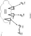
- FIGURE 1 is a block diagram illustrating an embodiment of a network 100, in accordance with certain embodiments.
- Network 100 includes one or more UE(s) 110 (which may be interchangeably referred to as wireless devices 110), network node(s) 115 (which may be interchangeably referred to as eNodeBs (eNBs) 115).
- UEs 110 may communicate with network nodes 115 over a wireless interface.
- UE 110A may transmit wireless signals to one or more of network nodes 115, and/or receive wireless signals from one or more of network nodes 115.
- the wireless signals may contain voice traffic, data traffic, control signals, and/or any other suitable information.
- an area of wireless signal coverage associated with a network node 115 may be referred to as a cell.
- UEs 110 may have D2D capability. Thus, UEs 110 may be able to receive signals from and/or transmit signals directly to another UE. For example, UE 110A may be able to receive signals from and/or transmit signals to UE 110D.
- network nodes 115 may interface with a radio network controller.
- the radio network controller may control network nodes 115 and may provide certain radio resource management functions, mobility management functions, and/or other suitable functions. In certain embodiments, the functions of the radio network controller may be performed by network node 115.
- the radio network controller may interface with a core network node. In certain embodiments, the radio network controller may interface with the core network node via an interconnecting network.
- the interconnecting network may refer to any interconnecting system capable of transmitting audio, video, signals, data, messages, or any combination of the preceding.
- the core network node may manage the establishment of communication sessions and various other functionalities for UEs 110. In some embodiments, the core network node may manage the establishment of communication sessions and various other functionality for UEs 110. UEs 110 may exchange certain signals with core network node using the non-access stratum layer. In non-access stratum signaling, signals between UEs 110 and the core network node may be transparently passed through the radio access network.
- network nodes 115 may interface with one or more network nodes over an internode interface. For example, network nodes 115A and 115B may interface over an X2 interface.
- UEs 110 described herein can be any type of wireless device capable of communicating with network nodes 115 or another UE over radio signals.
- UE 110 may also be a radio communication device, target device, device-to-device (D2D) UE, machine-type-communication UE or UE capable of machine to machine communication (M2M), a sensor equipped with UE, iPad, Tablet, mobile terminals, smart phone, laptop embedded equipped (LEE), laptop mounted equipment (LME), USB dongles, Customer Premises Equipment (CPE), etc.
- D2D device-to-device
- M2M machine to machine communication
- M2M machine to machine communication
- sensor equipped with UE iPad, Tablet
- smart phone laptop embedded equipped (LEE), laptop mounted equipment (LME), USB dongles
- CPE Customer Premises Equipment
- CPE Customer Premises Equipment
- Network node can be any kind of network node, which may comprise a base station, radio base station, base transceiver station, base station controller, network controller, evolved Node B (eNB), Node B, relay node, access point, radio access point, Remote Radio Unit (RRU), Remote Radio Head (RRH), or any other suitable network node.
- eNB evolved Node B
- RRU Remote Radio Unit
- RRH Remote Radio Head
- FIGURE 1 illustrates a particular arrangement of network 100
- network 100 may include any suitable number of UEs 110 and network nodes 115, as well as any additional elements suitable to support communication between UEs or between a UE and another communication device (such as a landline telephone).
- network 100 may include any suitable number of UEs 110 and network nodes 115, as well as any additional elements suitable to support communication between UEs or between a UE and another communication device (such as a landline telephone).
- RAT radio access technology
- the various embodiments described herein may be applicable to LTE FDD/TDD, WCDMA/HSPA, GSM/GERAN, WiFi, WLAN, CDMA2000, or any other suitable RAT.
- the communicating UEs 110 are within network coverage.
- the network also controls the D2D communication, such as synchronization, scheduling, etc.
- mode 1 UE 110 requests resources for sidelink transmission from a network node 115.
- UE 110A may request resources for sidelink transmission from network node 115A.
- mode 2 UE 110 selects resources for transmission from a known resource pool.
- a UE 110 when operating according to mode 1, may request different resources from network node 115A depending on what data is in UE buffer. For example, if UE 110A has only sidelink data in buffer, UE 110A may only request sidelink resources. If UE 110A has only uplink (UL) (e.g., LTE) data in buffer, UE 110A may only request UL resources. If UE 110A has both UL and sidelink data in buffer, UE 110A may request both UL and sidelink resources.
- UL uplink
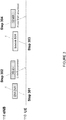
- FIGURE 2 is a signal flow diagram of the initiation of UL transmission by UE 110, in accordance with certain embodiments.
- UE 110 To start UL transmission (e.g., LTE UL transmission), UE 110 must request UL resources from network node 115.
- UE 110 sends a scheduling request (SR) to network node 115.
- SR scheduling request
- network node 115 grants UL resources to UE 110.
- the grant of UL resources may be scrambled with Cell Radio Network Temporary Identifier (C-RNTI).
- C-RNTI Cell Radio Network Temporary Identifier
- UE 110 sends a buffer status report (BSR) to network node 115 using the UL resource(s) granted at step 202.
- BSR buffer status report
- the BSR indicates an amount of data available for transmission in an uplink buffer associated with UE 110.
- Buffer status reporting for LTE data/logical channels is specified in 3GPP TS 36.321 v12.2.1. In LTE, buffer status reporting is done by means of MAC control elements comprising a (sub-)header part and a payload part.
- network node 115 grants UL resources to UE 110. The grant of UL resources is scrambled with C-RNTI.
- FIGURE 3 is a signal flow diagram of initiation of sidelink communication transmission, in accordance with certain embodiments.
- UE 110 to start sidelink communication in mode 1, UE 110 must request resources from network node 115.
- UE 110 sends a SR to network node 115.
- network node 115 grants UL resources to UE 110.
- the grant of UL resources may be scrambled with Cell Radio Network Temporary Identifier (C-RNTI).
- C-RNTI Cell Radio Network Temporary Identifier
- UE 110 sends a sidelink BSR to network node 115 using the UL resource(s) granted at step 302.
- network node 115 grants UL resources to UE 110.
- the sidelink BSR indicates an amount of sidelink data available for transmission in a sidelink buffer of the wireless device.
- the grant of UL resources may be scrambled with Sidelink-Radio Network Temporary Identifier (SL-RNTI) instead of C-RNTI described above in relation to FIGURE 2 .
- SL-RNTI Sidelink-Radio Network Temporary Identifier
- UE 110 when UE 110 has both UL data (e.g., LTE data) and sidelink data in buffer for transmission, UE 110 has to request/allocate resources for them serially. For example, in such a case UE 110 would first have to execute steps 201-204 described above in relation to FIGURE 2 for uplink, and then execute steps 301-304 described above in relation to FIGURE 3 for sidelink.
- UE 110 would first have to execute steps 201-204 described above in relation to FIGURE 2 for uplink, and then execute steps 301-304 described above in relation to FIGURE 3 for sidelink.
- Such a solution may have certain deficiencies.
- requiring UE 110 to serially request/allocate resources may increase service delay of sidelink.
- the present disclosure contemplates various embodiments that may advantageously reduce or eliminate the service delay associated with requesting/allocating resources for UL and sidelink data in buffer for transmission.
- a wireless device such as UE 110 may send a scheduling request to a network node, such as network node 115.
- UE 110 may receive, from network node 115 in response to the scheduling request, a grant of uplink resources.
- UE 110 may determine whether the granted uplink resources are at least equal to or larger than the resources required for transmission of both a buffer status report (BSR) and a sidelink BSR.
- BSR buffer status report
- sidelink BSR Upon determining that the granted uplink resources are at least equal to or larger than the resources required for transmission of both the BSR and the sidelink BSR, UE 110 may communicate the BSR and the sidelink BSR to network node 115 in a single medium access control (MAC) protocol data unit (PDU).
- MAC medium access control
- the wireless device may communicate the BSR and sidelink BSR in a various formats, thereby enabling joint allocation of UL and sidelink resources and eliminating the service delay associated with requesting/allocating resources for UL and sidelink data in buffer for transmission.
- network node 115 may: receive a scheduling request from UE 110; send, in response to receiving the scheduling request, a grant of uplink resources to UE 110; and receive, from UE 110 in response to the grant of uplink resources, a BSR and a sidelink BSR in a single MAC PDU.
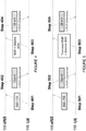
- FIGURE 4 is a signal flow diagram of the initiation of UL and sidelink transmission using a BSR and a sidelink BSR, in accordance with certain embodiments.
- UE 110 sends a SR to network node 115.
- network node 115 grants UL resources to UE 110.
- the grant of UL resources may be scrambled with Cell Radio Network Temporary Identifier (C-RNTI).
- C-RNTI Cell Radio Network Temporary Identifier
- the resources granted by network node 115 at step 402 may be enough for the transmission of BSR and sidelink BSR.
- the resources granted by network node 115 at step 402 may be at least equal to or larger than the resources required for transmission by UE 110 of both the BSR and the sidelink BSR.
- UE 110 transmits a BSR and a sidelink BSR within a single MAC PDU.
- network node 115 grants resources for UL and sidelink, respectively.
- FIGURE 5 is a signal flow diagram of the initiation of UL and sidelink transmission using a truncated BSR and a sidelink BSR, in accordance with certain embodiments.
- UE 110 sends a SR to network node 115.
- network node 115 grants UL resources to UE 110.
- the grant of UL resources may be scrambled with Cell Radio Network Temporary Identifier (C-RNTI).
- C-RNTI Cell Radio Network Temporary Identifier
- the granted uplink resources may be enough for the transmission of BSR, but not enough for BSR and sidelink BSR.
- UE 110 may replace the BSR with a truncated BSR and transmit the truncated BSR and sidelink BSR with a single MAC PDU.
- network node 115 may grant resources for further buffer status reporting (i.e., BSR and/or sidelink BSR) that could not be accommodated at step 503, and UL data, if any.
- BSR and/or sidelink BSR further buffer status reporting
- network node 115 may determine that UE 110 needs further resources to report buffer status for logical channels of logical channel groups for which buffer status was not reported yet.
- Network node 115 may adjust the amount of resources granted for UL data over an interface, such as the Uu interface, at step 504 to accommodate the further buffer status reporting which could not be accommodated at step 503.
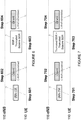
- FIGURE 6 is a signal flow diagram of the initiation of uplink and sidelink transmission using a BSR and a truncated sidelink BSR, in accordance with certain embodiments.
- UE 110 sends a SR to network node 115.
- network node 115 grants UL resources to UE 110.
- the grant of UL resources may be scrambled with Cell Radio Network Temporary Identifier (C-RNTI).
- C-RNTI Cell Radio Network Temporary Identifier
- the granted uplink resources may be enough for the transmission of BSR, but not enough for BSR and sidelink BSR.
- UE 110 may replace the sidelink BSR with a truncated sidelink BSR at step 603.
- network node 115 may grant resources for further buffer status reporting (i.e., BSR and/or sidelink BSR) that could not be accommodated at step 603, and UL data, if any. Based on receiving the truncated sidelink BSR, network node 115 may determine that UE 110 needs further resources to report sidelink buffer status for logical channels of logical channel groups for which buffer status was not reported yet. Network node 115 may adjust the amount of resources granted for sidelink data at step 604 to accommodate the further buffer status reporting which could not be accommodated at step 603.
- BSR and/or sidelink BSR resource for further buffer status reporting
- FIGURE 7 is a signal flow diagram of the initiation of uplink and sidelink transmission using a truncated BSR and a truncated sidelink BSR, in accordance with certain embodiments.
- UE 110 sends a SR to network node 115.
- network node 115 grants UL resources to UE 110.
- the grant of UL resources may be scrambled with Cell Radio Network Temporary Identifier (C-RNTI).
- C-RNTI Cell Radio Network Temporary Identifier
- replacing only BSR or sidelink BSR with a truncated BSR or truncated sidelink BSR, respectively may not be sufficient to fit buffer status reports for both LTE data/logical channels (Uu interface) and sidelink data/logical channels in a single MAC PDU.
- UE 110 may replace both BSR and sidelink BSR with a truncated BSR and a truncated sidelink BSR, respectively.
- the resources granted at step 702 may be enough for the transmission of BSR, but not enough for BSR and sidelink BSR.
- UE 110 may estimate and/or determine an amount of additional space which will be needed to include the sidelink BSR in a subsequent uplink transmission.
- UE 110 may increase the amount of data reported to be available for transmission by the estimated and/or determined amount to enable network node 115 to grant enough UL resources at step 704 for the successful inclusion and transmission of both the sidelink BSR and the data available for transmission reported for the logical channels of the logical channel groups for which buffer status was reported.
- UE 110 may determine an amount of additional resources needed to include the sidelink BSR in a subsequent uplink transmission.
- UE 110 may report, to network node 115, an increased amount of data available for transmission, the increased amount of data available for transmission including the estimated and/or determined amount of additional resources needed to include the sidelink BSR in the subsequent uplink transmission.
- UE 110 may communicate, in the subsequent uplink transmission, the sidelink BSR and the amount of data reported to be available for transmission.
- FIGURE 8 is a signal flow diagram of the initiation of uplink and sidelink transmission using a combined BSR, in accordance with certain embodiments.
- UE 110 sends a SR to network node 115.
- network node 115 grants UL resources to UE 110.
- the grant of UL resources may be scrambled with Cell Radio Network Temporary Identifier (C-RNTI).
- C-RNTI Cell Radio Network Temporary Identifier
- buffer status may be reported for both LTE logical channels (Uu interface) and sidelink logical channels with a combined BSR.
- the combined BSR may include information about buffer status for both types of logical channels.
- buffer status reporting may be done by means of MAC control elements comprising a (sub-)header part and a payload part.
- buffer status reporting for both LTE data/logical channels and ProSe data/logical channels may only require one (sub-header) component instead of one sub-header component for BSR and one for sidelink BSR.
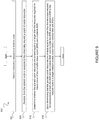
- FIGURE 9 is a flow chart of a method 900 in a wireless device, in accordance with an embodiment.
- the method begins at step 904, where the wireless device sends a scheduling request to a network node.
- the wireless device receives, from the network node in response to the scheduling request, a grant of uplink resources.
- the wireless device determines whether the granted uplink resources are at least equal to or larger than the resources required for transmission of both a BSR and a sidelink BSR.
- the BSR may indicate an amount of data available for transmission in an uplink buffer associated with the wireless device
- the sidelink BSR may indicate an amount of sidelink data available for transmission in a sidelink buffer of the wireless device.
- the wireless device upon determining that the granted uplink resources are at least equal to or larger than the resources required for transmission of both the BSR and the sidelink BSR, communicates the BSR and the sidelink BSR to the network node in a single MAC PDU.
- the method may further comprise upon determining that the granted uplink resources are not at least equal to or larger than the resources required for transmission of both the BSR and the sidelink BSR, communicating the BSR and a truncated sidelink BSR to the network node in a single MAC PDU.
- the method may further comprise upon determining that the granted uplink resources are not at least equal to or larger than the resources required for transmission of both the BSR and the sidelink BSR, communicating a truncated BSR and the sidelink BSR to the network node in a single MAC PDU.
- the method may further comprise upon determining that the granted uplink resources are not at least equal to or larger than the resources required for transmission of both the BSR and the sidelink BSR, communicating a truncated BSR and a truncated sidelink BSR to the network node in a single MAC PDU.
- the method may further comprise upon determining that the granted uplink resources are not at least equal to or larger than the resources required for transmission of both the BSR and the sidelink BSR, determining an amount of additional resources needed to include the sidelink BSR in a subsequent uplink transmission.
- the method may further comprise reporting, to the network node, an increased amount of data available for transmission, the increased amount of data available for transmission including the determined amount of additional resources needed to include the sidelink BSR in the subsequent uplink transmission, and communicating, in the subsequent uplink transmission, the sidelink BSR and the amount of data reported to be available for transmission.
- Communicating the BSR and the sidelink BSR to the network node in a single MAC PDU may comprise communicating a combined BSR.
- the combined BSR may comprise a single sub-header component and indicate buffer status for both LTE logical channels and sidelink logical channels.
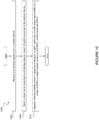
- FIGURE 10 is a flow chart of a method 1000 in a network node, in accordance with an embodiment.
- the method begins at step 1004, where the network node receives a scheduling request from a wireless device.
- the network node sends, in response to receiving the scheduling request, a grant of uplink resources to the wireless device.
- the granted uplink resources may be at least equal to or larger than the resources required for transmission by the wireless device of both a BSR and a sidelink BSR.
- the granted uplink resources are not at least equal to or larger than the resources required for transmission by the wireless device of both the BSR and the sidelink BSR.
- the BSR may indicate an amount of data available for transmission in an uplink buffer associated with the wireless device
- the sidelink BSR may indicate an amount of sidelink data available for transmission in a sidelink buffer of the wireless device.
- the network node receives, from the wireless device in response to the grant of uplink resources, a BSR and a sidelink BSR in a single MAC PDU.
- receiving the BSR and the sidelink BSR in a single MAC PDU may comprise receiving a combined BSR.
- the combined BSR may comprise a single sub-header component and indicate buffer status for both LTE logical channels and sidelink logical channels.
- the granted uplink resources may not be at least equal to or larger than the resources required for transmission by the wireless device of both the BSR and the sidelink BSR, and the received sidelink BSR may comprise a truncated sidelink BSR.
- the truncated sidelink BSR may indicate to the network node that the wireless device needs additional resources to report buffer status for one or more logical channels of logical channel groups for which buffer status was not reported.
- the method may further comprise granting an amount of resources adjusted to allow the wireless device to report buffer status for the one or more logical channels of logical channel groups for which buffer status was not reported.
- the granted uplink resources may not be at least equal to or larger than the resources required for transmission by the wireless device of both the BSR and the sidelink BSR, and the received BSR may comprise a truncated BSR.
- the truncated BSR may indicate to the network node that the wireless device needs additional resources to complete buffer status reporting.
- the granted uplink resources may not be at least equal to or larger than the resources required for transmission of both the BSR and the sidelink BSR
- the received BSR may comprise a truncated BSR
- the received sidelink BSR may comprise a truncated sidelink BSR.
- the granted uplink resources may not be at least equal to or larger than the resources required for transmission of both the BSR and the sidelink BSR.
- the method may further comprise receiving a report from the wireless device indicating an amount of data available for transmission, the amount of data available for transmission may be increased based on an amount of additional resources determined by the wireless device to be needed to include the sidelink BSR in a subsequent uplink transmission.
- the method may further comprise granting sufficient uplink resources so that the wireless device can include both the sidelink BSR and the amount of data reported to be available for transmission.
- FIGURE 11 is a block schematic of an exemplary wireless device 110, in accordance with certain embodiments.
- Wireless device 110 may refer to any type of wireless device communicating with a node and/or with another wireless device in a cellular or mobile communication system.
- Examples of wireless device 110 include a mobile phone, a smart phone, a PDA (Personal Digital Assistant), a portable computer (e.g., laptop, tablet), a sensor, a modem, a machine-type-communication (MTC) device / machine-to-machine (M2M) device, laptop embedded equipment (LEE), laptop mounted equipment (LME), USB dongles, a D2D capable device, or another device that can provide wireless communication.
- MTC machine-type-communication
- M2M machine-to-machine
- LME laptop mounted equipment
- USB dongles a D2D capable device, or another device that can provide wireless communication.
- a wireless device 110 may also be referred to as UE, a station (STA), a device, or a terminal in some embodiments.
- Wireless device 110 includes transceiver 1110, processor 1120, and memory 1130.
- transceiver 1110 facilitates transmitting wireless signals to and receiving wireless signals from network node 115 (e.g., via an antenna)
- processor 1120 executes instructions to provide some or all of the functionality described above as being provided by wireless device 110
- memory 1130 stores the instructions executed by processor 1120.
- Processor 1120 may include any suitable combination of hardware and software implemented in one or more modules to execute instructions and manipulate data to perform some or all of the described functions of wireless device 110.
- processor 1120 may include, for example, one or more computers, one or more central processing units (CPUs), one or more microprocessors, one or more applications, and/or other logic.
- CPUs central processing units
- microprocessors one or more applications, and/or other logic.
- Memory 1130 is generally operable to store instructions, such as a computer program, software, an application including one or more of logic, rules, algorithms, code, tables, etc. and/or other instructions capable of being executed by a processor.
- Examples of memory 1130 include computer memory (for example, Random Access Memory (RAM) or Read Only Memory (ROM)), mass storage media (for example, a hard disk), removable storage media (for example, a Compact Disk (CD) or a Digital Video Disk (DVD)), and/or or any other volatile or non-volatile, non-transitory computer-readable and/or computer-executable memory devices that store information.
- RAM Random Access Memory
- ROM Read Only Memory
- mass storage media for example, a hard disk
- removable storage media for example, a Compact Disk (CD) or a Digital Video Disk (DVD)
- CD Compact Disk
- DVD Digital Video Disk
- wireless device 110 may include additional components beyond those shown in FIGURE 11 that may be responsible for providing certain aspects of the wireless device's functionality, including any of the functionality described above and/or any additional functionality (including any functionality necessary to support the solution described above).
- wireless device 110 may include one or more modules.
- wireless device 110 may include a determining module, a communication module, a receiver module, an input module, a display module, and any other suitable modules.
- the determining module may perform the processing functions of wireless device 110. For example, the determining module may determine whether the granted uplink resources are at least equal to or larger than the resources required for transmission of both a BSR and a sidelink BSR. As another example, the determining module may determine an amount of additional resources needed to include the sidelink BSR in a subsequent uplink transmission.
- the determining module may include or be included in processor 1120.
- the determining module may include analog and/or digital circuitry configured to perform any of the functions of the determining module and/or processor 1120. The functions of the determining module described above may, in certain embodiments, be performed in one or more distinct modules.
- the communication module may perform the transmission functions of wireless device 110.
- the communication module may transmit messages to one or more of network nodes 115 of network 100.
- the communication module may send a scheduling request to a network node.
- the communication module may communicate the BSR and the sidelink BSR to the network node in a single MAC PDU.
- the communication module may communicate the BSR and a truncated sidelink BSR to the network node in a single MAC PDU.
- the communication module may communicate a truncated BSR and the sidelink BSR to the network node in a single MAC PDU.
- the network node may communicate a truncated BSR and a truncated sidelink BSR to the network node in a single MAC PDU.
- the communication module may report an increased amount of data available for transmission, the increased amount of data available for transmission including a determined amount of additional resources needed to include the sidelink BSR in a subsequent uplink transmission.
- the communication module may communicate, in the subsequent uplink transmission, the sidelink BSR and the amount of data reported to be available for transmission.
- the communication module may include a transmitter and/or a transceiver, such as transceiver 1110.
- the communication module may include circuitry configured to wirelessly transmit messages and/or signals. In particular embodiments, the communication module may receive messages and/or signals for transmission from the determining module.
- the receiving module may perform the receiving functions of wireless device 110. For example, the receiving module may receive, from a network node in response to a scheduling request, a grant of uplink resources.
- the receiving module may include a receiver and/or a transceiver.
- the receiving module may include circuitry configured to wirelessly receive messages and/or signals. In particular embodiments, the receiving module may communicate received messages and/or signals to the determining module.
- the input module may receive user input intended for wireless device 110.
- the input module may receive key presses, button presses, touches, swipes, audio signals, video signals, and/or any other appropriate signals.
- the input module may include one or more keys, buttons, levers, switches, touchscreens, microphones, and/or cameras.
- the input module may communicate received signals to the determining module.
- the display module may present signals on a display of wireless device 110.
- the display module may include the display and/or any appropriate circuitry and hardware configured to present signals on the display.
- the display module may receive signals to present on the display from the determining module.
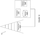
- FIGURE 12 is a block schematic of an exemplary network node 115, in accordance with certain embodiments.
- Network node 115 may be any type of radio network node or any network node that communicates with a UE and/or with another network node.
- Examples of network node 115 include an eNodeB, a node B, a base station, a wireless access point (e.g., a Wi-Fi access point), a low power node, a base transceiver station (BTS), relay, donor node controlling relay, transmission points, transmission nodes, remote RF unit (RRU), remote radio head (RRH), multi-standard radio (MSR) radio node such as MSR BS, nodes in distributed antenna system (DAS), O&M, OSS, SON, positioning node (e.g., E-SMLC), MDT, or any other suitable network node.
- MSR multi-standard radio
- Network nodes 115 may be deployed throughout network 100 as a homogenous deployment, heterogeneous deployment, or mixed deployment.
- a homogeneous deployment may generally describe a deployment made up of the same (or similar) type of network nodes 115 and/or similar coverage and cell sizes and inter-site distances.
- a heterogeneous deployment may generally describe deployments using a variety of types of network nodes 115 having different cell sizes, transmit powers, capacities, and inter-site distances.
- a heterogeneous deployment may include a plurality of low-power nodes placed throughout a macro-cell layout.
- Mixed deployments may include a mix of homogenous portions and heterogeneous portions.
- Network node 115 may include one or more of transceiver 1210, processor 1220, memory 1230, and network interface 1240.
- transceiver 1210 facilitates transmitting wireless signals to and receiving wireless signals from wireless device 110 (e.g., via an antenna)
- processor 1220 executes instructions to provide some or all of the functionality described above as being provided by a network node 115
- memory 1230 stores the instructions executed by processor 1220
- network interface 1240 communicates signals to backend network components, such as a gateway, switch, router, Internet, Public Switched Telephone Network (PSTN), core network nodes 130, radio network controllers 120, etc.
- PSTN Public Switched Telephone Network
- Processor 1220 may include any suitable combination of hardware and software implemented in one or more modules to execute instructions and manipulate data to perform some or all of the described functions of network node 115.
- processor 1220 may include, for example, one or more computers, one or more central processing units (CPUs), one or more microprocessors, one or more applications, and/or other logic.
- CPUs central processing units
- microprocessors one or more applications, and/or other logic.
- Memory 1230 is generally operable to store instructions, such as a computer program, software, an application including one or more of logic, rules, algorithms, code, tables, etc. and/or other instructions capable of being executed by a processor.
- Examples of memory 1230 include computer memory (for example, Random Access Memory (RAM) or Read Only Memory (ROM)), mass storage media (for example, a hard disk), removable storage media (for example, a Compact Disk (CD) or a Digital Video Disk (DVD)), and/or or any other volatile or non-volatile, non-transitory computer-readable and/or computer-executable memory devices that store information.
- RAM Random Access Memory
- ROM Read Only Memory
- mass storage media for example, a hard disk
- removable storage media for example, a Compact Disk (CD) or a Digital Video Disk (DVD)
- CD Compact Disk
- DVD Digital Video Disk
- network interface 1240 is communicatively coupled to processor 1220 and may refer to any suitable device operable to receive input for network node 115, send output from network node 115, perform suitable processing of the input or output or both, communicate to other devices, or any combination of the preceding.
- Network interface 1240 may include appropriate hardware (e.g., port, modem, network interface card, etc.) and software, including protocol conversion and data processing capabilities, to communicate through a network.
- network node 115 may include a determining module, a communication module, a receiving module, and any other suitable modules.
- one or more of the determining module, communication module, receiving module, or any other suitable module may be implemented using one or more processors 1220 of FIGURE 12 .
- the functions of two or more of the various modules may be combined into a single module.
- the determining module may perform the processing functions of network node 115. For example, the determining module may grant an amount of resources adjusted to allow a wireless device to report buffer status for one or more logical channels of logical channel groups for which buffer status was not reported. As another example, the determining module may grant sufficient uplink resources so that the wireless device can include both the sidelink BSR and an amount of data reported to be available for transmission.
- the determining module may include or be included in processor 1220.
- the determining module may include analog and/or digital circuitry configured to perform any of the functions of the determining module and/or processor 1220. The functions of the determining module described above may, in certain embodiments, be performed in one or more distinct modules.
- the communication module may perform the transmission functions of network node 115.
- the communication module may transmit messages to one or more of wireless devices 110.
- the communication module may send, in response to receiving a scheduling request, a grant of uplink resources to the wireless device.
- the communication module may include a transmitter and/or a transceiver, such as transceiver 1210.
- the communication module may include circuitry configured to wirelessly transmit messages and/or signals.
- the communication module may receive messages and/or signals for transmission from the determining module or any other module.
- the receiving module may perform the receiving functions of network node 115.
- the receiving module may receive any suitable information from a wireless device. For example, the receiving module may receive a scheduling request from a wireless device. As another example, the receiving module may receive, from the wireless device in response to a grant of uplink resources, a BSR and a sidelink BSR in a single MAC PDU. As yet another example, the receiving module may receive a report from the wireless device indicating an amount of data available for transmission, the amount of additional data available for transmission increased based on an amount of additional resources determined by the wireless device to be needed to include the sidelink BSR in a subsequent uplink transmission.
- the receiving module may include a receiver and/or a transceiver.
- the receiving module may include circuitry configured to wirelessly receive messages and/or signals. In particular embodiments, the receiving module may communicate received messages and/or signals to the determining module or any other suitable module.
- network node 115 may include additional components beyond those shown in FIGURE 12 that may be responsible for providing certain aspects of the radio network node's functionality, including any of the functionality described above and/or any additional functionality (including any functionality necessary to support the solutions described above).
- the various different types of network nodes may include components having the same physical hardware but configured (e.g., via programming) to support different radio access technologies, or may represent partly or entirely different physical components.
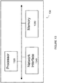
- FIGURE 13 is a block schematic of an exemplary radio network controller or core network node 130, in accordance with certain embodiments.
- network nodes can include a mobile switching center (MSC), a serving GPRS support node (SGSN), a mobility management entity (MME), a radio network controller (RNC), a base station controller (BSC), and so on.
- the radio network controller or core network node 130 include processor 1320, memory 1330, and network interface 1340.
- processor 1320 executes instructions to provide some or all of the functionality described above as being provided by the network node
- memory 1330 stores the instructions executed by processor 1320
- network interface 1340 communicates signals to any suitable node, such as a gateway, switch, router, Internet, Public Switched Telephone Network (PSTN), network nodes 115, radio network controllers or core network nodes 130, etc.
- PSTN Public Switched Telephone Network
- Processor 1320 may include any suitable combination of hardware and software implemented in one or more modules to execute instructions and manipulate data to perform some or all of the described functions of the radio network controller or core network node 130.
- processor 1320 may include, for example, one or more computers, one or more central processing units (CPUs), one or more microprocessors, one or more applications, and/or other logic.
- CPUs central processing units
- microprocessors one or more applications, and/or other logic.
- Memory 1330 is generally operable to store instructions, such as a computer program, software, an application including one or more of logic, rules, algorithms, code, tables, etc. and/or other instructions capable of being executed by a processor.
- Examples of memory 1330 include computer memory (for example, Random Access Memory (RAM) or Read Only Memory (ROM)), mass storage media (for example, a hard disk), removable storage media (for example, a Compact Disk (CD) or a Digital Video Disk (DVD)), and/or or any other volatile or non-volatile, non-transitory computer-readable and/or computer-executable memory devices that store information.
- RAM Random Access Memory
- ROM Read Only Memory
- mass storage media for example, a hard disk
- removable storage media for example, a Compact Disk (CD) or a Digital Video Disk (DVD)
- CD Compact Disk
- DVD Digital Video Disk
- network interface 1340 is communicatively coupled to processor 1320 and may refer to any suitable device operable to receive input for the network node, send output from the network node, perform suitable processing of the input or output or both, communicate to other devices, or any combination of the preceding.
- Network interface 1340 may include appropriate hardware (e.g., port, modem, network interface card, etc.) and software, including protocol conversion and data processing capabilities, to communicate through a network.
- network node may include additional components beyond those shown in FIGURE 13 that may be responsible for providing certain aspects of the network node's functionality, including any of the functionality described above and/or any additional functionality (including any functionality necessary to support the solution described above).
Landscapes
- Engineering & Computer Science (AREA)
- Computer Networks & Wireless Communication (AREA)
- Signal Processing (AREA)
- Mobile Radio Communication Systems (AREA)
Claims (15)
- Verfahren in einer drahtlosen Vorrichtung (110), umfassend:Senden (904) einer Dispositionsanforderung an einen Netzwerkknoten (115); undEmpfangen (908) einer Freigabe von Uplink-Ressourcen vom Netzwerkknoten;dadurch gekennzeichnet, dass das Verfahren ferner umfasst:Bestimmen (912), ob die freigegebenen Uplink-Ressourcen wenigstens gleich wie oder größer als die Ressourcen sind, die zur Übertragung sowohl eines Pufferstatusberichts, BSR, als auch eines Sidelink-BSRs erforderlich sind; undKommunizieren (916) bei Bestimmen, dass die freigegebenen Uplink-Ressourcen wenigstens gleich wie oder größer als die Ressourcen sind, die zur Übertragung sowohl des BSRs als auch des Sidelink-BSRs erforderlich sind, des BSRs und des Sidelink-BSRs in einer einzigen Medienzugriffssteuerungs, MAC,-Protokolldateneinheit, PDU, an den Netzwerkknoten.
- Verfahren nach Anspruch 1, ferner umfassend bei Bestimmen, dass die freigegebenen Uplink-Ressourcen nicht wenigstens gleich wie oder größer als die Ressourcen sind, die zur Übertragung sowohl des BSRs als auch des Sidelink-BSRs erforderlich sind, ein Kommunizieren (603) des BSRs und eines gekürzten Sidelink-BSRs in einer einzigen MAC-PDU an den Netzwerkknoten, Kommunizieren (503) eines gekürzten BSRs und des Sidelink-BSRs in einer einzigen MAC-PDU an den Netzwerkknoten oder Kommunizieren (703) eines gekürzten BSRs und eines gekürzten Sidelink-BSRs in einer einzigen MAC-PDU an den Netzwerkknoten.
- Verfahren nach Anspruch 1, ferner umfassend bei Bestimmen, dass die freigegebenen Uplink-Ressourcen nicht wenigstens gleich wie oder größer als die Ressourcen sind, die zur Übertragung sowohl des BSRs als auch des Sidelink-BSRs erforderlich sind:Bestimmen einer Menge von zusätzlichen Ressourcen, die benötigt wird, um den Sidelink-BSR in eine folgende Uplink-Übertragung einzubeziehen;Melden einer erhöhten Menge von Daten, die zur Übertragung verfügbar ist, an den Netzwerkknoten, wobei die erhöhte Menge von Daten, die zur Übertragung verfügbar ist, die bestimmte Menge von zusätzlichen Ressourcen umfasst, die zum Einbeziehen des Sidelink-BSRs in die folgende Uplink-Übertragung benötigt wird; undKommunizieren des Sidelink-BSRs und der als zur Übertragung verfügbar gemeldeten Menge von Daten in der folgenden Uplink-Übertragung.
- Verfahren nach Anspruch 1, wobei das Kommunizieren des BSRs und des Sidelink-BSRs in einer einzigen MAC-PDU an den Netzwerkknoten ein Kommunizieren (803) eines kombinierten BSRs umfasst, wobei der kombinierte BSR eine einzige Subheader-Komponente umfasst und sowohl den Pufferstatus für logische LTE-Kanäle als auch logische Sidelink-Kanäle anzeigt.
- Verfahren nach Anspruch 1, wobei:der BSR eine Menge von Daten anzeigt, die zur Übertragung in einem Uplink-Puffer verfügbar ist, der mit der drahtlosen Vorrichtung assoziiert ist; undder Sidelink-BSR eine Menge von Sidelink-Daten anzeigt, die zur Übertragung in einem Sidelink-Puffer mit der drahtlosen Vorrichtung verfügbar ist.
- Verfahren in einem Netzwerkknoten (115), umfassend:Empfangen (1004) einer Dispositionsanforderung von einer drahtlosen Vorrichtung (110); undSenden (1008) einer Freigabe von Uplink-Ressourcen an die drahtlose Vorrichtung;dadurch gekennzeichnet, dass das Verfahren ferner ein Empfangen (1012) eines Pufferstatusberichts, BSR, und eines Sidelink-BSRs in einer einzigen Medienzugriffssteuerungs, MAC,-Protokolldateneinheit, PDU, von der drahtlosen Vorrichtung in Reaktion auf die Freigabe von Uplink-Ressourcen umfasst, wobei die freigegebenen Uplink-Ressourcen wenigstens gleich wie oder größer als die Ressourcen sind, die zur Übertragung sowohl eines BSRs als auch eines Sidelink-BSRs durch die drahtlose Vorrichtung erforderlich sind.
- Verfahren nach Anspruch 6, wobei:die freigegebenen Uplink-Ressourcen nicht wenigstens gleich wie oder größer als die Ressourcen sind, die zur Übertragung sowohl des BSRs als auch des Sidelink-BSRs durch die drahtlose Vorrichtung erforderlich sind; undder empfangene Sidelink-BSR einen gekürzten Sidelink-BSR umfasst (603), wobei der gekürzte Sidelink-BSR dem Netzwerkknoten anzeigt, dass die drahtlose Vorrichtung zusätzliche Ressourcen benötigt, um den Pufferstatus für einen oder mehrere logische Kanäle von Gruppen logischer Kanäle zu melden, für welche der Pufferstatus nicht gemeldet wurde.
- Verfahren nach Anspruch 7, ferner umfassend ein Freigeben einer Menge von Ressourcen, die angepasst ist, um der drahtlosen Vorrichtung zu ermöglichen, den Pufferstatus für den einen oder die mehreren logischen Kanäle von Gruppen logischer Kanäle zu melden, für welche der Pufferstatus nicht gemeldet wurde.
- Verfahren nach Anspruch 6, wobei die freigegebenen Uplink-Ressourcen nicht wenigstens gleich wie oder größer als die Ressourcen sind, die zur Übertragung sowohl des BSRs als auch des Sidelink-BSRs durch die drahtlose Vorrichtung erforderlich sind, und der empfangene BSR einen gekürzten BSR umfasst (503), wobei der gekürzte BSR dem Netzwerkknoten anzeigt, dass die drahtlose Vorrichtung zusätzliche Ressourcen zum Durchführen des Meldens des Pufferstatus benötigt.
- Verfahren nach Anspruch 6, wobei:die freigegebenen Uplink-Ressourcen nicht wenigstens gleich wie oder größer als die Ressourcen sind, die zur Übertragung sowohl des BSRs als auch des Sidelink-BSRs erforderlich sind;der empfangene BSR einen gekürzten BSR umfasst (703); undder empfangene des Sidelink-BSR einen gekürzten Sidelink-BSR umfasst (703).
- Verfahren nach Anspruch 6, wobei die freigegebenen Uplink-Ressourcen nicht wenigstens gleich wie oder größer als die Ressourcen sind, die zur Übertragung sowohl des BSRs als auch des Sidelink-BSRs erforderlich sind, und das Verfahren ferner umfasst:Empfangen eines Berichts von der drahtlosen Vorrichtung, der eine Menge von Daten anzeigt, die zur Übertragung verfügbar ist, wobei die Menge von Daten, die zur Übertragung verfügbar ist, basierend auf einer Menge von zusätzlichen Ressourcen erhöht wird, die als von der drahtlosen Vorrichtung zum Einbeziehen des Sidelink-BSRs in eine folgende Uplink-Übertragung benötigt bestimmt wird; undFreigeben von genügen Uplink-Ressourcen, damit die drahtlose Vorrichtung sowohl den Sidelink-BSR als auch die als zur Übertragung verfügbar gemeldete Menge von Daten einbeziehen kann.
- Verfahren nach Anspruch 6, wobei das Empfangen des BSRs und des Sidelink-BSRs in einer einzigen MAC-PDU von der drahtlosen Vorrichtung in Reaktion auf die Freigabe von Uplink-Ressourcen ein Empfangen eines kombinierten BSRs umfasst (803), wobei der kombinierte BSR eine einzige Subheader-Komponente umfasst und sowohl den Pufferstatus für logische LTE-Kanäle als auch logische Sidelink-Kanäle anzeigt.
- Verfahren nach Anspruch 6, wobei:der BSR eine Menge von Daten anzeigt, die zur Übertragung in einem Uplink-Puffer verfügbar ist, der mit der drahtlosen Vorrichtung assoziiert ist; undder Sidelink-BSR eine Menge von Sidelink-Daten anzeigt, die zur Übertragung in des Sidelink-Puffer der drahtlosen Vorrichtung verfügbar ist.
- Drahtlose Vorrichtung (110), umfassend:
einen oder mehrere Prozessoren (1120), die zum Durchführen des Verfahrens nach einem der Ansprüche 1 bis 5 konfiguriert sind. - Netzwerkknoten (115), umfassend:
einen oder mehrere Prozessoren (1220), die zum Durchführen des Verfahrens nach einem der Ansprüche 6 bis 14 konfiguriert sind.
Priority Applications (4)
| Application Number | Priority Date | Filing Date | Title |
|---|---|---|---|
| PL15750140T PL3178277T3 (pl) | 2014-08-08 | 2015-08-06 | Koordynacja między sekwencyjnym BSR i komórkowym BSR |
| PL19204056T PL3624534T3 (pl) | 2014-08-08 | 2015-08-06 | Koordynacja między sekwencyjnym BSR i komórkowym BSR |
| DK19204056.6T DK3624534T3 (da) | 2014-08-08 | 2015-08-06 | Koordinering mellem prosa-BSR og cellulær BSR |
| EP19204056.6A EP3624534B1 (de) | 2014-08-08 | 2015-08-06 | Koordination zwischen prosa-bsr und zellularer bsr |
Applications Claiming Priority (2)
| Application Number | Priority Date | Filing Date | Title |
|---|---|---|---|
| US201462035091P | 2014-08-08 | 2014-08-08 | |
| PCT/IB2015/055988 WO2016020881A1 (en) | 2014-08-08 | 2015-08-06 | Coordination between prose bsr and cellular bsr |
Related Child Applications (2)
| Application Number | Title | Priority Date | Filing Date |
|---|---|---|---|
| EP19204056.6A Division EP3624534B1 (de) | 2014-08-08 | 2015-08-06 | Koordination zwischen prosa-bsr und zellularer bsr |
| EP19204056.6A Division-Into EP3624534B1 (de) | 2014-08-08 | 2015-08-06 | Koordination zwischen prosa-bsr und zellularer bsr |
Publications (2)
| Publication Number | Publication Date |
|---|---|
| EP3178277A1 EP3178277A1 (de) | 2017-06-14 |
| EP3178277B1 true EP3178277B1 (de) | 2019-11-27 |
Family
ID=53836147
Family Applications (2)
| Application Number | Title | Priority Date | Filing Date |
|---|---|---|---|
| EP19204056.6A Active EP3624534B1 (de) | 2014-08-08 | 2015-08-06 | Koordination zwischen prosa-bsr und zellularer bsr |
| EP15750140.4A Active EP3178277B1 (de) | 2014-08-08 | 2015-08-06 | Koordination zwischen prosa-bsr und zellularer bsr |
Family Applications Before (1)
| Application Number | Title | Priority Date | Filing Date |
|---|---|---|---|
| EP19204056.6A Active EP3624534B1 (de) | 2014-08-08 | 2015-08-06 | Koordination zwischen prosa-bsr und zellularer bsr |
Country Status (9)
| Country | Link |
|---|---|
| US (3) | US10057918B2 (de) |
| EP (2) | EP3624534B1 (de) |
| KR (1) | KR101982421B1 (de) |
| DK (2) | DK3624534T3 (de) |
| ES (2) | ES2765454T3 (de) |
| MX (1) | MX358807B (de) |
| PL (2) | PL3178277T3 (de) |
| PT (1) | PT3178277T (de) |
| WO (1) | WO2016020881A1 (de) |
Cited By (1)
| Publication number | Priority date | Publication date | Assignee | Title |
|---|---|---|---|---|
| EP3979743B1 (de) * | 2019-07-03 | 2023-12-13 | Guangdong Oppo Mobile Telecommunications Corp., Ltd. | Sidelink-implementierungsverfahren und -vorrichtung |
Families Citing this family (38)
| Publication number | Priority date | Publication date | Assignee | Title |
|---|---|---|---|---|
| US9923834B2 (en) * | 2014-05-09 | 2018-03-20 | Futurewei Technologies, Inc. | System and method for triggering and sending device-to-device buffer status report and scheduling request |
| US10057918B2 (en) * | 2014-08-08 | 2018-08-21 | Telefonaktiebolaget Lm Ericsson (Publ) | Coordination between prose BSR and cellular BSR |
| WO2016036196A1 (ko) * | 2014-09-04 | 2016-03-10 | 엘지전자 주식회사 | 무선 통신 시스템에서 d2d통신 및 wan통신을 위한 버퍼 운영 방법 및 이를 위한 장치 |
| US9769699B2 (en) * | 2014-09-17 | 2017-09-19 | Innovative Sonic Corporation | Method and apparatus for performing device to device (D2D) content estimation and triggering of buffer status reporting (BSR) in a wireless communication system |
| WO2016047900A1 (en) * | 2014-09-23 | 2016-03-31 | Lg Electronics Inc. | Method for priority handling for buffer status reporting in a d2d communication system and device therefor |
| CN107079327A (zh) * | 2014-11-06 | 2017-08-18 | Lg 电子株式会社 | 在d2d通信系统中取消侧链路缓冲器状态报告的方法及其设备 |
| US10111170B2 (en) * | 2014-11-06 | 2018-10-23 | Lg Electronics Inc. | Method for canceling scheduling requests triggered by a sidelink buffer status report in a D2D communication system and device therefor |
| CN107113651B (zh) | 2014-12-30 | 2020-12-08 | Lg 电子株式会社 | 在无线通信系统中发送用于双向传输的缓冲器状态报告的方法和装置 |
| WO2016153264A1 (ko) * | 2015-03-24 | 2016-09-29 | 삼성전자 주식회사 | 무선 통신 시스템에서 메시지를 송수신하는 방법 및 장치 |
| WO2016163762A1 (en) * | 2015-04-07 | 2016-10-13 | Lg Electronics Inc. | Method and apparatus for performing buffer status reporting procedure for relaying in wireless communication system |
| US10506623B2 (en) | 2015-08-21 | 2019-12-10 | Lg Electronics Inc. | Method for triggering a BSR for sidelink data in a D2D communication system and device therefor |
| TW201735581A (zh) * | 2016-03-16 | 2017-10-01 | 瑞昱半導體股份有限公司 | 網路通訊裝置與電子裝置 |
| WO2017160070A1 (ko) * | 2016-03-17 | 2017-09-21 | 엘지전자 주식회사 | 무선 통신 시스템에서 사이드링크 자원의 점유 정도를 보고하는 방법 및 장치 |
| EP3255950A1 (de) * | 2016-06-06 | 2017-12-13 | ASUSTek Computer Inc. | Verfahren und vorrichtung zur ressourcenzuweisung für ein d2d relais in einem drahtloskommunikationssystem |
| WO2017212314A1 (en) * | 2016-06-08 | 2017-12-14 | Telefonaktiebolaget Lm Ericsson (Publ) | Systems and methods for signaling and using transmit patterns |
| EP3972343A1 (de) | 2016-11-03 | 2022-03-23 | Guangdong Oppo Mobile Telecommunications Corp., Ltd. | Verfahren zum umschalten eines kommunikationsmodus sowie endgerätevorrichtung und netzwerkvorrichtung |
| CN109479292B (zh) * | 2017-02-20 | 2023-06-02 | 瑞典爱立信有限公司 | 用于侧链路传输控制的方法和装置 |
| CN109246743B (zh) * | 2017-04-28 | 2021-10-15 | 华为技术有限公司 | 一种波束管理方法及终端设备、网络设备 |
| CN109152025B (zh) * | 2017-06-16 | 2024-04-26 | 华为技术有限公司 | 通信方法、终端及基站 |
| CN110999397B (zh) * | 2017-08-11 | 2022-04-29 | 华为技术有限公司 | 一种设备发现方法及相关设备 |
| ES2944438T3 (es) * | 2018-02-09 | 2023-06-21 | Beijing Xiaomi Mobile Software Co Ltd | Método de retención de activación y aparato de retención de activación |
| CN110351684A (zh) * | 2018-04-04 | 2019-10-18 | 华为技术有限公司 | 传输数据的方法及其装置和系统 |
| US11889514B2 (en) * | 2018-06-28 | 2024-01-30 | Interdigital Patent Holdings, Inc. | Sidelink buffer status reports and scheduling requests for new radio vehicle sidelink shared channel data transmissions |
| CN110830955B (zh) * | 2018-08-14 | 2024-01-05 | 夏普株式会社 | 用户设备的控制方法、基站的控制方法以及用户设备 |
| WO2020064850A1 (en) * | 2018-09-27 | 2020-04-02 | Telefonaktiebolaget Lm Ericsson (Publ) | Latency reduction for network scheduled sidelink resource allocation |
| CN113273227A (zh) * | 2019-01-10 | 2021-08-17 | 联发科技(新加坡)私人有限公司 | 在用于车辆通信的单独资源池中的缓冲区状态报告传输 |
| CN111263457B (zh) * | 2019-01-23 | 2022-03-01 | 维沃移动通信有限公司 | 一种副链路缓存状态报告发送、接收方法和设备 |
| CN113287358B (zh) * | 2019-02-15 | 2024-09-20 | 索尼集团公司 | 实现附加数据的传送的方法和无线设备 |
| CN111866945B (zh) * | 2019-04-30 | 2023-03-10 | 华为技术有限公司 | 取消待处理sr的方法及装置 |
| EP3735075B1 (de) * | 2019-05-02 | 2026-01-07 | Comcast Cable Communications, LLC | D2d-sidelink-funkkommunikation mit angabe von empfängerinformationen |
| EP3973739A1 (de) * | 2019-05-21 | 2022-03-30 | Telefonaktiebolaget LM Ericsson (publ) | Verfahren und vorrichtungen zur ermöglichung einer gruppenübertragung in kommunikationsnetzen |
| CN111800866B (zh) | 2019-08-15 | 2023-09-19 | 维沃移动通信有限公司 | 资源请求方法、资源分配方法、装置、设备及介质 |
| WO2021068185A1 (en) * | 2019-10-11 | 2021-04-15 | Qualcomm Incorporated | Joint scheduling of sidelink and uu link |
| US11889541B2 (en) | 2020-01-24 | 2024-01-30 | Qualcomm Incorporated | Superposition transmission of sidelink and uplink |
| US11706660B2 (en) * | 2020-04-20 | 2023-07-18 | Qualcomm Incorporated | Sidelink and UU link buffer status report |
| GB2597271B (en) * | 2020-07-17 | 2023-06-14 | Canon Kk | Buffer status report signaling both buffered uplink traffic and buffered direct link traffic |
| CN114390691A (zh) * | 2020-10-21 | 2022-04-22 | 索尼公司 | 电子设备和通信方法 |
| CN115022978B (zh) * | 2022-05-18 | 2025-07-25 | 同济大学 | 基于自适应分组与强化学习的无线网络上行链路调度方法 |
Family Cites Families (24)
| Publication number | Priority date | Publication date | Assignee | Title |
|---|---|---|---|---|
| TWI336905B (en) | 2002-05-17 | 2011-02-01 | Semiconductor Energy Lab | Evaporation method, evaporation device and method of fabricating light emitting device |
| US8406179B2 (en) * | 2007-08-07 | 2013-03-26 | Samsung Electronics Co., Ltd. | Method and apparatus for performing random access procedure in a mobile communication system |
| US7993708B2 (en) | 2008-07-01 | 2011-08-09 | Clearedge Power, Inc. | Control for reformer, fuel cell and battery management system in a stationary power plant |
| KR100939722B1 (ko) * | 2008-08-11 | 2010-02-01 | 엘지전자 주식회사 | 데이터 전송 방법 및 이를 위한 사용자 기기 |
| US20140023008A1 (en) | 2010-12-27 | 2014-01-23 | Jae-Young Ahn | Method for establishing a device-to-device link connection and scheduling for device-to-device communication and terminal relaying |
| US11496948B2 (en) * | 2012-10-19 | 2022-11-08 | Samsung Electronics Co., Ltd. | System and method for ad-hoc/network assisted device discovery protocol for device to device communications |
| RU2627296C2 (ru) | 2013-01-11 | 2017-08-07 | ЭлДжи ЭЛЕКТРОНИКС ИНК. | Способ сообщения состояния буфера и устройство связи для этого |
| CN105191178B (zh) * | 2013-05-01 | 2019-06-28 | 三星电子株式会社 | 用于设备到设备通信系统的方法和装置 |
| KR102237199B1 (ko) * | 2013-06-28 | 2021-04-07 | 삼성전자주식회사 | 디바이스-투-디바이스 통신 방법 및 장치 |
| KR102130296B1 (ko) * | 2013-07-31 | 2020-07-08 | 삼성전자주식회사 | 단말 대 단말 통신을 지원하는 단말 및 그 동작 방법 |
| WO2015099321A1 (en) * | 2013-12-25 | 2015-07-02 | Lg Electronics Inc. | Method for reporting a buffer status and device therefor |
| US9769644B2 (en) * | 2014-03-14 | 2017-09-19 | Intel IP Corporation | Systems, methods, and devices for device-to-device communication mode selection |
| US10165572B2 (en) * | 2014-03-19 | 2018-12-25 | Lg Electronics Inc. | Method and apparatus for canceling triggered buffer status report for device-to-device transmission in wireless communication system |
| JP2017515431A (ja) * | 2014-03-19 | 2017-06-08 | インターデイジタル パテント ホールディングス インコーポレイテッド | デバイスツーデバイス同期 |
| CN106031284B (zh) * | 2014-03-20 | 2019-11-08 | 夏普株式会社 | 终端装置、集成电路以及无线通信方法 |
| CN103874049B (zh) * | 2014-03-31 | 2017-02-15 | 电信科学技术研究院 | 一种缓冲区状态上报bsr触发方法及装置 |
| US9661653B2 (en) * | 2014-05-08 | 2017-05-23 | Intel IP Corporation | Device to-device (D2D) communications |
| US20150327220A1 (en) * | 2014-05-09 | 2015-11-12 | Innovative Sonic Corporation | Method and apparatus for reception of a downlink control information (dci) for device-to-device (d2d) resource scheduling |
| US9923834B2 (en) * | 2014-05-09 | 2018-03-20 | Futurewei Technologies, Inc. | System and method for triggering and sending device-to-device buffer status report and scheduling request |
| EP2975903B1 (de) * | 2014-07-16 | 2018-01-31 | Innovative Sonic Corporation | Verfahren und vorrichtung zur durchführung eines direktzugriffsverfahrens (ra) für vorrichtung-zu-vorrichtung (d2d)-kommunikation in einem drahtlosen kommunikationssystem |
| US9907056B2 (en) * | 2014-08-06 | 2018-02-27 | Futurewei Technologies, Inc. | System and method for allocating resources for device-to-device communications |
| US10057918B2 (en) * | 2014-08-08 | 2018-08-21 | Telefonaktiebolaget Lm Ericsson (Publ) | Coordination between prose BSR and cellular BSR |
| WO2016047900A1 (en) * | 2014-09-23 | 2016-03-31 | Lg Electronics Inc. | Method for priority handling for buffer status reporting in a d2d communication system and device therefor |
| US9930690B2 (en) * | 2014-11-07 | 2018-03-27 | Futurewei Technologies, Inc. | System and method for processing buffer status reports in random access procedures |
-
2015
- 2015-08-04 US US14/817,661 patent/US10057918B2/en active Active
- 2015-08-06 WO PCT/IB2015/055988 patent/WO2016020881A1/en not_active Ceased
- 2015-08-06 KR KR1020177004628A patent/KR101982421B1/ko active Active
- 2015-08-06 PL PL15750140T patent/PL3178277T3/pl unknown
- 2015-08-06 ES ES15750140T patent/ES2765454T3/es active Active
- 2015-08-06 DK DK19204056.6T patent/DK3624534T3/da active
- 2015-08-06 DK DK15750140.4T patent/DK3178277T3/da active
- 2015-08-06 EP EP19204056.6A patent/EP3624534B1/de active Active
- 2015-08-06 MX MX2016017244A patent/MX358807B/es active IP Right Grant
- 2015-08-06 PL PL19204056T patent/PL3624534T3/pl unknown
- 2015-08-06 EP EP15750140.4A patent/EP3178277B1/de active Active
- 2015-08-06 PT PT157501404T patent/PT3178277T/pt unknown
- 2015-08-06 ES ES19204056T patent/ES2880785T3/es active Active
-
2018
- 2018-07-17 US US16/037,665 patent/US10588142B2/en active Active
-
2020
- 2020-01-28 US US16/774,187 patent/US11665688B2/en active Active
Non-Patent Citations (1)
| Title |
|---|
| None * |
Cited By (2)
| Publication number | Priority date | Publication date | Assignee | Title |
|---|---|---|---|---|
| EP3979743B1 (de) * | 2019-07-03 | 2023-12-13 | Guangdong Oppo Mobile Telecommunications Corp., Ltd. | Sidelink-implementierungsverfahren und -vorrichtung |
| US12167401B2 (en) | 2019-07-03 | 2024-12-10 | Guangdong Oppo Mobile Telecommunications Corp., Ltd. | Method for SL BSR implementation and related products |
Also Published As
| Publication number | Publication date |
|---|---|
| US20160044707A1 (en) | 2016-02-11 |
| US20200163106A1 (en) | 2020-05-21 |
| DK3178277T3 (da) | 2020-03-02 |
| KR20170040268A (ko) | 2017-04-12 |
| EP3624534B1 (de) | 2021-05-19 |
| PL3624534T3 (pl) | 2021-11-29 |
| PT3178277T (pt) | 2020-01-14 |
| EP3178277A1 (de) | 2017-06-14 |
| MX358807B (es) | 2018-09-04 |
| US10057918B2 (en) | 2018-08-21 |
| MX2016017244A (es) | 2017-04-25 |
| US11665688B2 (en) | 2023-05-30 |
| WO2016020881A1 (en) | 2016-02-11 |
| PL3178277T3 (pl) | 2020-06-01 |
| ES2765454T3 (es) | 2020-06-09 |
| DK3624534T3 (da) | 2021-06-28 |
| KR101982421B1 (ko) | 2019-05-24 |
| ES2880785T3 (es) | 2021-11-25 |
| US20180324838A1 (en) | 2018-11-08 |
| EP3624534A1 (de) | 2020-03-18 |
| US10588142B2 (en) | 2020-03-10 |
Similar Documents
| Publication | Publication Date | Title |
|---|---|---|
| US11665688B2 (en) | Coordination between prose BSR and cellular BSR | |
| US11082857B2 (en) | Inter-carrier D2D resource allocation | |
| EP3036951B1 (de) | Verfahren und netzwerkknoten zur verwaltung von ressourcen | |
| EP3143816B1 (de) | Zuweisung von komponententrägern bei betrieb mit doppelter konnektivität | |
| US10499318B2 (en) | Provisioning transmission pools for inter-carrier prose direct discovery | |
| US11240769B2 (en) | System information for narrowband | |
| CN110192414B (zh) | 利用轮询ue id列表的寻呼 | |
| CN121240185A (zh) | 用于无线通信的方法和装置 | |
| US10667290B2 (en) | Method for handling users with different timing alignment requirements | |
| EP4184968A1 (de) | Verfahren zur auswahl von direktzugriffsressourcen und zugehörige vorrichtung | |
| WO2017051381A1 (en) | Systems, methods, and apparatuses for reducing delay for sidelink transmissions |
Legal Events
| Date | Code | Title | Description |
|---|---|---|---|
| STAA | Information on the status of an ep patent application or granted ep patent |
Free format text: STATUS: THE INTERNATIONAL PUBLICATION HAS BEEN MADE |
|
| PUAI | Public reference made under article 153(3) epc to a published international application that has entered the european phase |
Free format text: ORIGINAL CODE: 0009012 |
|
| STAA | Information on the status of an ep patent application or granted ep patent |
Free format text: STATUS: REQUEST FOR EXAMINATION WAS MADE |
|
| 17P | Request for examination filed |
Effective date: 20170103 |
|
| AK | Designated contracting states |
Kind code of ref document: A1 Designated state(s): AL AT BE BG CH CY CZ DE DK EE ES FI FR GB GR HR HU IE IS IT LI LT LU LV MC MK MT NL NO PL PT RO RS SE SI SK SM TR |
|
| AX | Request for extension of the european patent |
Extension state: BA ME |
|
| DAV | Request for validation of the european patent (deleted) | ||
| DAX | Request for extension of the european patent (deleted) | ||
| STAA | Information on the status of an ep patent application or granted ep patent |
Free format text: STATUS: EXAMINATION IS IN PROGRESS |
|
| 17Q | First examination report despatched |
Effective date: 20190218 |
|
| REG | Reference to a national code |
Ref country code: DE Ref legal event code: R079 Ref document number: 602015042527 Country of ref document: DE Free format text: PREVIOUS MAIN CLASS: H04W0072120000 Ipc: H04W0076140000 |
|
| GRAP | Despatch of communication of intention to grant a patent |
Free format text: ORIGINAL CODE: EPIDOSNIGR1 |
|
| STAA | Information on the status of an ep patent application or granted ep patent |
Free format text: STATUS: GRANT OF PATENT IS INTENDED |
|
| RIC1 | Information provided on ipc code assigned before grant |
Ipc: H04W 76/14 20180101AFI20190611BHEP Ipc: H04W 72/12 20090101ALI20190611BHEP Ipc: H04W 28/02 20090101ALN20190611BHEP |
|
| INTG | Intention to grant announced |
Effective date: 20190628 |
|
| GRAS | Grant fee paid |
Free format text: ORIGINAL CODE: EPIDOSNIGR3 |
|
| GRAA | (expected) grant |
Free format text: ORIGINAL CODE: 0009210 |
|
| STAA | Information on the status of an ep patent application or granted ep patent |
Free format text: STATUS: THE PATENT HAS BEEN GRANTED |
|
| AK | Designated contracting states |
Kind code of ref document: B1 Designated state(s): AL AT BE BG CH CY CZ DE DK EE ES FI FR GB GR HR HU IE IS IT LI LT LU LV MC MK MT NL NO PL PT RO RS SE SI SK SM TR |
|
| REG | Reference to a national code |
Ref country code: GB Ref legal event code: FG4D |
|
| REG | Reference to a national code |
Ref country code: CH Ref legal event code: EP |
|
| REG | Reference to a national code |
Ref country code: AT Ref legal event code: REF Ref document number: 1208175 Country of ref document: AT Kind code of ref document: T Effective date: 20191215 |
|
| REG | Reference to a national code |
Ref country code: DE Ref legal event code: R096 Ref document number: 602015042527 Country of ref document: DE |
|
| REG | Reference to a national code |
Ref country code: IE Ref legal event code: FG4D |
|
| REG | Reference to a national code |
Ref country code: PT Ref legal event code: SC4A Ref document number: 3178277 Country of ref document: PT Date of ref document: 20200114 Kind code of ref document: T Free format text: AVAILABILITY OF NATIONAL TRANSLATION Effective date: 20191226 |
|
| REG | Reference to a national code |
Ref country code: SE Ref legal event code: TRGR |
|
| REG | Reference to a national code |
Ref country code: NL Ref legal event code: FP |
|
| REG | Reference to a national code |
Ref country code: DK Ref legal event code: T3 Effective date: 20200226 |
|
| REG | Reference to a national code |
Ref country code: LT Ref legal event code: MG4D |
|
| PG25 | Lapsed in a contracting state [announced via postgrant information from national office to epo] |
Ref country code: FI Free format text: LAPSE BECAUSE OF FAILURE TO SUBMIT A TRANSLATION OF THE DESCRIPTION OR TO PAY THE FEE WITHIN THE PRESCRIBED TIME-LIMIT Effective date: 20191127 Ref country code: LT Free format text: LAPSE BECAUSE OF FAILURE TO SUBMIT A TRANSLATION OF THE DESCRIPTION OR TO PAY THE FEE WITHIN THE PRESCRIBED TIME-LIMIT Effective date: 20191127 Ref country code: BG Free format text: LAPSE BECAUSE OF FAILURE TO SUBMIT A TRANSLATION OF THE DESCRIPTION OR TO PAY THE FEE WITHIN THE PRESCRIBED TIME-LIMIT Effective date: 20200227 Ref country code: NO Free format text: LAPSE BECAUSE OF FAILURE TO SUBMIT A TRANSLATION OF THE DESCRIPTION OR TO PAY THE FEE WITHIN THE PRESCRIBED TIME-LIMIT Effective date: 20200227 Ref country code: LV Free format text: LAPSE BECAUSE OF FAILURE TO SUBMIT A TRANSLATION OF THE DESCRIPTION OR TO PAY THE FEE WITHIN THE PRESCRIBED TIME-LIMIT Effective date: 20191127 |
|
| REG | Reference to a national code |
Ref country code: GR Ref legal event code: EP Ref document number: 20200400253 Country of ref document: GR Effective date: 20200511 |
|
| PG25 | Lapsed in a contracting state [announced via postgrant information from national office to epo] |
Ref country code: HR Free format text: LAPSE BECAUSE OF FAILURE TO SUBMIT A TRANSLATION OF THE DESCRIPTION OR TO PAY THE FEE WITHIN THE PRESCRIBED TIME-LIMIT Effective date: 20191127 Ref country code: RS Free format text: LAPSE BECAUSE OF FAILURE TO SUBMIT A TRANSLATION OF THE DESCRIPTION OR TO PAY THE FEE WITHIN THE PRESCRIBED TIME-LIMIT Effective date: 20191127 Ref country code: IS Free format text: LAPSE BECAUSE OF FAILURE TO SUBMIT A TRANSLATION OF THE DESCRIPTION OR TO PAY THE FEE WITHIN THE PRESCRIBED TIME-LIMIT Effective date: 20200327 |
|
| REG | Reference to a national code |
Ref country code: ES Ref legal event code: FG2A Ref document number: 2765454 Country of ref document: ES Kind code of ref document: T3 Effective date: 20200609 |
|
| PG25 | Lapsed in a contracting state [announced via postgrant information from national office to epo] |
Ref country code: AL Free format text: LAPSE BECAUSE OF FAILURE TO SUBMIT A TRANSLATION OF THE DESCRIPTION OR TO PAY THE FEE WITHIN THE PRESCRIBED TIME-LIMIT Effective date: 20191127 |
|
| PG25 | Lapsed in a contracting state [announced via postgrant information from national office to epo] |
Ref country code: CZ Free format text: LAPSE BECAUSE OF FAILURE TO SUBMIT A TRANSLATION OF THE DESCRIPTION OR TO PAY THE FEE WITHIN THE PRESCRIBED TIME-LIMIT Effective date: 20191127 Ref country code: EE Free format text: LAPSE BECAUSE OF FAILURE TO SUBMIT A TRANSLATION OF THE DESCRIPTION OR TO PAY THE FEE WITHIN THE PRESCRIBED TIME-LIMIT Effective date: 20191127 Ref country code: RO Free format text: LAPSE BECAUSE OF FAILURE TO SUBMIT A TRANSLATION OF THE DESCRIPTION OR TO PAY THE FEE WITHIN THE PRESCRIBED TIME-LIMIT Effective date: 20191127 |
|
| REG | Reference to a national code |
Ref country code: DE Ref legal event code: R097 Ref document number: 602015042527 Country of ref document: DE |
|
| PG25 | Lapsed in a contracting state [announced via postgrant information from national office to epo] |
Ref country code: SK Free format text: LAPSE BECAUSE OF FAILURE TO SUBMIT A TRANSLATION OF THE DESCRIPTION OR TO PAY THE FEE WITHIN THE PRESCRIBED TIME-LIMIT Effective date: 20191127 Ref country code: SM Free format text: LAPSE BECAUSE OF FAILURE TO SUBMIT A TRANSLATION OF THE DESCRIPTION OR TO PAY THE FEE WITHIN THE PRESCRIBED TIME-LIMIT Effective date: 20191127 |
|
| REG | Reference to a national code |
Ref country code: AT Ref legal event code: MK05 Ref document number: 1208175 Country of ref document: AT Kind code of ref document: T Effective date: 20191127 |
|
| PLBE | No opposition filed within time limit |
Free format text: ORIGINAL CODE: 0009261 |
|
| STAA | Information on the status of an ep patent application or granted ep patent |
Free format text: STATUS: NO OPPOSITION FILED WITHIN TIME LIMIT |
|
| 26N | No opposition filed |
Effective date: 20200828 |
|
| PG25 | Lapsed in a contracting state [announced via postgrant information from national office to epo] |
Ref country code: AT Free format text: LAPSE BECAUSE OF FAILURE TO SUBMIT A TRANSLATION OF THE DESCRIPTION OR TO PAY THE FEE WITHIN THE PRESCRIBED TIME-LIMIT Effective date: 20191127 Ref country code: SI Free format text: LAPSE BECAUSE OF FAILURE TO SUBMIT A TRANSLATION OF THE DESCRIPTION OR TO PAY THE FEE WITHIN THE PRESCRIBED TIME-LIMIT Effective date: 20191127 |
|
| PG25 | Lapsed in a contracting state [announced via postgrant information from national office to epo] |
Ref country code: MC Free format text: LAPSE BECAUSE OF FAILURE TO SUBMIT A TRANSLATION OF THE DESCRIPTION OR TO PAY THE FEE WITHIN THE PRESCRIBED TIME-LIMIT Effective date: 20191127 |
|
| REG | Reference to a national code |
Ref country code: CH Ref legal event code: PL |
|
| PG25 | Lapsed in a contracting state [announced via postgrant information from national office to epo] |
Ref country code: CH Free format text: LAPSE BECAUSE OF NON-PAYMENT OF DUE FEES Effective date: 20200831 Ref country code: LI Free format text: LAPSE BECAUSE OF NON-PAYMENT OF DUE FEES Effective date: 20200831 Ref country code: LU Free format text: LAPSE BECAUSE OF NON-PAYMENT OF DUE FEES Effective date: 20200806 |
|
| REG | Reference to a national code |
Ref country code: BE Ref legal event code: MM Effective date: 20200831 |
|
| PG25 | Lapsed in a contracting state [announced via postgrant information from national office to epo] |
Ref country code: IE Free format text: LAPSE BECAUSE OF NON-PAYMENT OF DUE FEES Effective date: 20200806 Ref country code: BE Free format text: LAPSE BECAUSE OF NON-PAYMENT OF DUE FEES Effective date: 20200831 |
|
| PG25 | Lapsed in a contracting state [announced via postgrant information from national office to epo] |
Ref country code: MT Free format text: LAPSE BECAUSE OF FAILURE TO SUBMIT A TRANSLATION OF THE DESCRIPTION OR TO PAY THE FEE WITHIN THE PRESCRIBED TIME-LIMIT Effective date: 20191127 Ref country code: CY Free format text: LAPSE BECAUSE OF FAILURE TO SUBMIT A TRANSLATION OF THE DESCRIPTION OR TO PAY THE FEE WITHIN THE PRESCRIBED TIME-LIMIT Effective date: 20191127 |
|
| PG25 | Lapsed in a contracting state [announced via postgrant information from national office to epo] |
Ref country code: MK Free format text: LAPSE BECAUSE OF FAILURE TO SUBMIT A TRANSLATION OF THE DESCRIPTION OR TO PAY THE FEE WITHIN THE PRESCRIBED TIME-LIMIT Effective date: 20191127 |
|
| PGFP | Annual fee paid to national office [announced via postgrant information from national office to epo] |
Ref country code: NL Payment date: 20220826 Year of fee payment: 8 |
|
| PGFP | Annual fee paid to national office [announced via postgrant information from national office to epo] |
Ref country code: TR Payment date: 20220727 Year of fee payment: 8 Ref country code: SE Payment date: 20220827 Year of fee payment: 8 Ref country code: IT Payment date: 20220819 Year of fee payment: 8 Ref country code: ES Payment date: 20220901 Year of fee payment: 8 Ref country code: DK Payment date: 20220829 Year of fee payment: 8 |
|
| PGFP | Annual fee paid to national office [announced via postgrant information from national office to epo] |
Ref country code: PL Payment date: 20220720 Year of fee payment: 8 Ref country code: GR Payment date: 20220829 Year of fee payment: 8 |
|
| P01 | Opt-out of the competence of the unified patent court (upc) registered |
Effective date: 20230523 |
|
| REG | Reference to a national code |
Ref country code: DK Ref legal event code: EBP Effective date: 20230831 |
|
| REG | Reference to a national code |
Ref country code: NL Ref legal event code: MM Effective date: 20230901 |
|
| PG25 | Lapsed in a contracting state [announced via postgrant information from national office to epo] |
Ref country code: GR Free format text: LAPSE BECAUSE OF NON-PAYMENT OF DUE FEES Effective date: 20240307 |
|
| PG25 | Lapsed in a contracting state [announced via postgrant information from national office to epo] |
Ref country code: GR Free format text: LAPSE BECAUSE OF NON-PAYMENT OF DUE FEES Effective date: 20240307 |
|
| PG25 | Lapsed in a contracting state [announced via postgrant information from national office to epo] |
Ref country code: NL Free format text: LAPSE BECAUSE OF NON-PAYMENT OF DUE FEES Effective date: 20230901 |
|
| PG25 | Lapsed in a contracting state [announced via postgrant information from national office to epo] |
Ref country code: SE Free format text: LAPSE BECAUSE OF NON-PAYMENT OF DUE FEES Effective date: 20230807 Ref country code: NL Free format text: LAPSE BECAUSE OF NON-PAYMENT OF DUE FEES Effective date: 20230901 |
|
| PG25 | Lapsed in a contracting state [announced via postgrant information from national office to epo] |
Ref country code: DK Free format text: LAPSE BECAUSE OF NON-PAYMENT OF DUE FEES Effective date: 20230831 |
|
| PG25 | Lapsed in a contracting state [announced via postgrant information from national office to epo] |
Ref country code: IT Free format text: LAPSE BECAUSE OF NON-PAYMENT OF DUE FEES Effective date: 20230806 Ref country code: DK Free format text: LAPSE BECAUSE OF NON-PAYMENT OF DUE FEES Effective date: 20230831 |
|
| REG | Reference to a national code |
Ref country code: ES Ref legal event code: FD2A Effective date: 20240927 |
|
| PG25 | Lapsed in a contracting state [announced via postgrant information from national office to epo] |
Ref country code: ES Free format text: LAPSE BECAUSE OF NON-PAYMENT OF DUE FEES Effective date: 20230807 |
|
| PG25 | Lapsed in a contracting state [announced via postgrant information from national office to epo] |
Ref country code: PL Free format text: LAPSE BECAUSE OF NON-PAYMENT OF DUE FEES Effective date: 20230806 |
|
| PG25 | Lapsed in a contracting state [announced via postgrant information from national office to epo] |
Ref country code: PL Free format text: LAPSE BECAUSE OF NON-PAYMENT OF DUE FEES Effective date: 20230806 Ref country code: ES Free format text: LAPSE BECAUSE OF NON-PAYMENT OF DUE FEES Effective date: 20230807 |
|
| PGFP | Annual fee paid to national office [announced via postgrant information from national office to epo] |
Ref country code: PT Payment date: 20250722 Year of fee payment: 11 |
|
| PGFP | Annual fee paid to national office [announced via postgrant information from national office to epo] |
Ref country code: DE Payment date: 20250827 Year of fee payment: 11 |
|
| PGFP | Annual fee paid to national office [announced via postgrant information from national office to epo] |
Ref country code: GB Payment date: 20250827 Year of fee payment: 11 |
|
| PGFP | Annual fee paid to national office [announced via postgrant information from national office to epo] |
Ref country code: FR Payment date: 20250825 Year of fee payment: 11 |
|
| PG25 | Lapsed in a contracting state [announced via postgrant information from national office to epo] |
Ref country code: TR Free format text: LAPSE BECAUSE OF NON-PAYMENT OF DUE FEES Effective date: 20230806 |