EP3178409B1 - Ensembles de rétracteur pour intervention chirurgicale chez un patient - Google Patents
Ensembles de rétracteur pour intervention chirurgicale chez un patient Download PDFInfo
- Publication number
- EP3178409B1 EP3178409B1 EP17151651.1A EP17151651A EP3178409B1 EP 3178409 B1 EP3178409 B1 EP 3178409B1 EP 17151651 A EP17151651 A EP 17151651A EP 3178409 B1 EP3178409 B1 EP 3178409B1
- Authority
- EP
- European Patent Office
- Prior art keywords
- engagement
- elongate support
- support member
- retractor
- arm
- Prior art date
- Legal status (The legal status is an assumption and is not a legal conclusion. Google has not performed a legal analysis and makes no representation as to the accuracy of the status listed.)
- Active
Links
Images




Classifications
-
- A—HUMAN NECESSITIES
- A61—MEDICAL OR VETERINARY SCIENCE; HYGIENE
- A61B—DIAGNOSIS; SURGERY; IDENTIFICATION
- A61B17/00—Surgical instruments, devices or methods
- A61B17/02—Surgical instruments, devices or methods for holding wounds open, e.g. retractors; Tractors
-
- A—HUMAN NECESSITIES
- A61—MEDICAL OR VETERINARY SCIENCE; HYGIENE
- A61B—DIAGNOSIS; SURGERY; IDENTIFICATION
- A61B1/00—Instruments for performing medical examinations of the interior of cavities or tubes of the body by visual or photographical inspection, e.g. endoscopes; Illuminating arrangements therefor
- A61B1/32—Devices for opening or enlarging the visual field, e.g. of a tube of the body
-
- A—HUMAN NECESSITIES
- A61—MEDICAL OR VETERINARY SCIENCE; HYGIENE
- A61B—DIAGNOSIS; SURGERY; IDENTIFICATION
- A61B17/00—Surgical instruments, devices or methods
-
- A—HUMAN NECESSITIES
- A61—MEDICAL OR VETERINARY SCIENCE; HYGIENE
- A61B—DIAGNOSIS; SURGERY; IDENTIFICATION
- A61B17/00—Surgical instruments, devices or methods
- A61B17/02—Surgical instruments, devices or methods for holding wounds open, e.g. retractors; Tractors
- A61B17/0206—Surgical instruments, devices or methods for holding wounds open, e.g. retractors; Tractors with antagonistic arms as supports for retractor elements
-
- A—HUMAN NECESSITIES
- A61—MEDICAL OR VETERINARY SCIENCE; HYGIENE
- A61B—DIAGNOSIS; SURGERY; IDENTIFICATION
- A61B17/00—Surgical instruments, devices or methods
- A61B17/02—Surgical instruments, devices or methods for holding wounds open, e.g. retractors; Tractors
- A61B17/0293—Surgical instruments, devices or methods for holding wounds open, e.g. retractors; Tractors with ring member to support retractor elements
Definitions
- the present application relates to retractor assemblies for use in performing surgery in a patient, and more particularly, but not exclusively, relates to assemblies for tissue retraction to facilitate a procedure within a patient through the retracted tissue.
- US 2004/0049101 A1 discloses a surgical retractor with arms.
- One nonlimiting embodiment of the present application is directed to an assembly for surgery in a patient that includes a pair of arm members removably positioned on and movable along an elongate support member.
- Each arm member includes a rotatable engagement portion engageable with a respective retractor portion and a locking element releasably biased into engagement with the engagement portion.
- the engagement between the locking elements and the engagement portion limits rotation of the engagement portions to a single direction about a longitudinal axis of a respective arm member.
- Instruments, assemblies and methods for performing surgery including spinal surgeries that include one or more techniques such as laminotomy, laminectomy, foramenotomy, facetectomy, discectomy, interbody fusion, spinal nucleus or disc replacement, and implant insertion including plates, rods, and bone engaging fasteners, for example, are provided.
- the surgery is performed through a working channel or passageway through skin and/or tissue of the patient provided by a retractor assembly which includes a retractor. Viewing of the surgical site at the working end of the retractor can be accomplished with naked eye visualization, microscopic viewing devices, loupes, viewing instruments mounted on the retractor, positioned over the retractor, positioned in other portals in the body, and/or through a viewing system such as lateral fluoroscopy.
- the retractor is movable in situ to increase the size of the working channel to facilitate access to the working space at the distal end of the retractor while minimizing trauma to tissue surrounding the retractor.
- the retractor can be used with any surgical approach to the spine, including anterior, posterior, posterior mid-line, lateral, postero-lateral, and/or antero-lateral approaches, and in other regions besides the spine.
- Assembly 10 includes an elongate support member 12 including an elongate body 14 extending along a longitudinal axis L between a first end 16 and an opposite second end 18.
- First end 16 and second end 18 are generally structured to engage with one or more operating room support structures. More particularly, first end 16 includes a pair of oppositely positioned flange members 20a and 20b which define a slot 22 positioned therebetween.
- second end 18 includes a pair of oppositely positioned flange members 24a and 24b which define a slot 26 positioned therebetween.
- slots 22, 26 can be configured to receive a corresponding fastening member from the operating room support structure.
- Elongate support member 12 also includes a plurality of teeth 28 positioned on proximal surface 15 thereof.
- teeth 28 positioned on proximal surface 15 thereof.
- other surface features such as serrations, knurling, notches, grooves, indentations, projections and/or polymeric, ceramic or metallic coatings, could be provided on proximal surface 15 of elongate support member 12 in addition to or in lieu of teeth 28, as well as on one or more additional surfaces of elongate support member 12. Still, in other embodiments, it is contemplated that elongate support member 12 is free from any surface features.
- Assembly 10 also includes a first arm member 30 and a second arm member 130.
- First and second arm members 30, 130 are removably positioned on and movable along elongate support member 12, further details of which will be provided below.
- First arm member 30 includes an external housing 32 that extends between a proximal end 34 and a distal end 36.
- External housing 32 also includes a pair of lateral sidewalls 38, 40 which extend between an upper surface 42 and a lower surface 44.
- Distal end 36 includes an engagement portion 46 which is structured to engage with first retractor portion 300.
- second arm member 130 includes an external housing 132 that extends between a proximal end 134 and a distal end 136.
- External housing 132 also includes a pair of lateral sidewalls 138, 140 which extend between an upper surface 142 and a lower surface 144.
- Distal end 136 includes an engagement portion 146 which is structured to engage with second retractor portion 340.
- First and second arm members 30, 130 are generally operable to move relative to each other to provide a working channel 390 to a surgical site between first retractor portion 300 and second retractor portion 340. Further details regarding operation of assembly 10 are provided below.
- Retractor portion 300 includes a retractor blade 302 extending between a first end 304 and an opposite second end 306.
- Retractor portion 300 also includes an engagement assembly 308 positioned at first end 304 of retractor blade 302.
- Engagement assembly 308 is structured to engage with engagement portion 46 of first arm member 30 and includes an extension 310 extending laterally from first end 304.
- extension 310 extends substantially transversely to and in the same plane as first end 304 of retractor blade 302.
- extension 310 could be angled relative to first end 304 and/or could be positioned in a separate plane from first end 304.
- Extension 310 is defined by an enlarged portion 312 and a reduced profile stem portion 314.
- Retractor portion 340 includes a retractor blade 342 extending between a first end 344 and an opposite second end 346. Retractor portion 340 also includes an engagement assembly 348 positioned at first end 344 of retractor blade 342. Engagement assembly 348 is structured to engage with engagement portion 146 of second arm member 130 and includes an extension 350 extending laterally from first end 344. In the illustrated embodiment, extension 350 extends substantially transversely to and in the same plane as first end 344 of retractor blade 342. However, in other non-illustrated embodiments, it is contemplated that extension 350 could be angled relative to first end 344 and/or could be positioned in a separate plane from first end 344. Extension 350 is defined by an enlarged portion 352 and a reduced profile stem portion 354.
- Engagement portions 46 and 146 each includes a respective recess 48, 148 which opens to receive a respective engagement assembly 308, 348 of first and second retractor portions 300, 340.
- Recess 48 includes a keyway opening 50 and a receptacle (not shown) in communication with opening 50. The receptacle is enlarged relative to opening 50, and is shaped to receive enlarged portion 312 of engagement assembly 308 of retractor portion 300 therein.
- recess 148 includes a keyway opening 150 and a receptacle (not shown) in communication with opening 150. The receptacle is enlarged relative to opening 150, and is shaped to receive enlarged portion 352 of engagement assembly 348 of retractor portion 340 therein.
- Openings 50, 150 and the receptacles in communication therewith are open along the bottom surface 44, 144 of the respective engagement portions 46, 146 to facilitate placement of enlarged portions 312, 352 of engagement assemblies 308, 348 therein.
- enlarged portions 312, 352 are positioned in the respective receptacle of engagement portions 46, 146, stems 314, 354 of engagement assemblies 308, 348 extend through openings 50, 150.
- engagement portions 46, 146 can include a locking or clamping mechanism structured to releasably hold engagement assemblies 308, 348 in engagement therewith.
- a ball detent mechanism is utilized. More particularly, a ball member 127 is biased distally by a spring member 126 and protrudes into the receptacle of engagement portion 46.
- Ball member 127 can be depressed proximally from the receptacle of engagement portion 46 when enlarged portion 312 of engagement assembly 308 is being positioned therein, and then return to its distally biased position and be received within an indentation (not shown) on enlarged portion 312 once engagement assembly 308 is positioned in the receptacle of engagement portion 46. Ball member 127 can be similarly depressed to facilitate removal of retractor portion 300 from engagement portion 46 by a user. While the ball detent mechanism has been described with respect to first arm member 30 and retractor portion 300, it should be appreciated that this arrangement and the description thereof are also applicable to the engagement between first arm member 130 and retractor portion 340.
- retractor portions 300, 340 ends 306, 346 can be beveled to facilitate insertion in an incision, although non-beveled ends are also contemplated.
- Retractor blade 302 can be positioned adjacent to or mated with retractor blade 342 along adjacent ones of the longitudinal edges 316 of retractor blade 302 and longitudinal edges 356 of retractor blade 342.
- a working channel 390 is formed between first retractor blade 302 and second retractor blade 342 and extends between and opens at first ends 304, 344 and second ends 306, 346.
- retractor portion 300, 340 may be provided with engagement members structured to engage with one or more surgical instruments, such as a separation instrument, which are used with assembly 10.
- one or both of arm members 30, 130 can include an engagement member in addition to or in lieu of the engagement members on retractor portions 300, 340.
- Retractor blades 302, 342 are insertable through an incision in skin and tissue of a patient to provide working channel 390 to a surgical site. It is contemplated that retractor blades 302, 342 are inserted through skin and tissue in an insertion configuration for working channel 390. In the insertion configuration, working channel 390 is substantially enclosed or circumscribed by retractor blades 302, 342. After insertion into the patient, working channel 390 can be enlarged by separating first retractor blade 302 and second retractor blade 342. Separation of retractor blades 302, 342 increases the size of working channel 390 from first ends 304, 344 to second ends 306, 346.
- Working channel 390 can have a size in the insertion configuration that allows passage of one or more surgical instruments and/or implants to the surgical location in the patient's body. It may be desirable during surgery to provide greater access to the surgical site in the patient's body beyond the locations provided through working channel 390 in its insertion configuration.
- First retractor blade 302 and second retractor blade 342 are movable away from one another to enlarge working channel 390.
- a space is formed between the adjacent longitudinal edges 316, 356 of retractor blades 302, 342. The space between the adjacent longitudinal edges 316, 356 exposes enlarged working channel 390 to skin and tissue of the patient between the separated first retractor blade 302 and second retractor blade 342.
- This exposed tissue can also be accessed by the surgeon through the enlarged working channel 390 with one or more instruments and/or implants. It is further contemplated that a shield, guard or tissue retractor could be placed in enlarged working channel 390 to maintain the exposed tissue away from the enlarged working channel 390.
- additional tissue retractors that can be positioned in the enlarged working channel 390 between retractor blades 302, 342 are provided in U.S. Patent Publication No. 2004/0176665 to Branch et al. Viewing instruments can be positioned in or adjacent to working channel 390 to facilitate surgeon viewing of the surgical site.
- an endoscopic viewing element can be mounted on the first end of one of retractor blades 302, 342 with a scope portion extending along working channel 390.
- a microscopic viewing element can be positioned over the first end of one of retractor blades 302, 342 for viewing the surgical site.
- Other imaging techniques such as lateral fluoroscopy, can be used alone or in combination with the endoscopic and microscopic viewing elements.
- other instruments can be mounted on the first end of one or both of retractor blades 302, 342, such as nerve root retractors, tissue retractors, forceps, cutter, drills, scrapers, reamers, separators, rongeurs, taps, cauterization instruments, irrigation and/or aspiration instruments, illumination instruments, inserter instruments, and the like for use in surgical procedures at the surgical site.
- Such viewing instruments and other instruments can be employed with working channel 390 in its initial insertion configuration and/or its enlarged configuration.
- retractor blades 302, 342 may be structured to align and releasably couple with one another in the insertion configuration.
- retractor blade 302 can include an alignment pin structured to engage with a corresponding alignment aperture on retractor blade 342.
- retractor blade 342 may include an alignment pin structured to engage with a corresponding alignment aperture on retractor blade 302.
- Other arrangements are also contemplated for aligning and releasably coupling first retractor blade 302 and second retractor blade 342 to one another.
- Examples of such arrangements include dovetail connections, fasteners, threaded coupling members, clamping members, snap rings, compression bands, straps, ball-detent mechanisms, and releasably interlocking cams or tabs, just to name a few possibilities.
- First retractor blade 302 has a perimeter length along second end 306 which can be about the same as the perimeter length of retractor blade 302 at first end 304.
- Second retractor blade 342 includes a perimeter length along second end 346 which can be about the same as the perimeter length of retractor blade 342 adjacent first end 344.
- Retractor blades 302, 342 can have a semi-circular cross-section, and form a generally circular cross-section for the working channel when placed adjacent one another.
- Other cross-sectional shapes are also contemplated for first and second retractor blades 302, 342, such as, for example, any open sided polygonal shape, curved shape, or combined curved/polygonal shape.
- working channel 390 can have a cylindrical or frusto-conical shape with, for example, a cross-section that is oval, elliptical, circular, curved, polygonal, or combined polygonal/curved in shape.
- Retractor blades 302, 342 can be provided with sufficient rigidity between their first and second ends to separate and maintain separation of tissue when blades 302, 342 are initially inserted and also when the tissue is retracted by moving first retractor blade 302 and second retractor blade 342 away from one another.
- retractor blades 302, 342 can include a thickness which provides sufficient rigidity to resist bending or bowing under the forces exerted on it by the retracted tissue.
- the semicircular shaped cross-section of blades 302, 342 can be configured to provide a sufficient section modulus or moment of inertia in the direction of movement of blades 302, 342 to resist bending, bowing and/or deflection forces applied during such movement.
- retractor assembly 10 is in spinal surgery. It is contemplated that, after insertion of retractor blades 302, 342, they are separated predominantly in one direction to retract muscle and tissue which extends between first and second retractor portions 300, 340.
- first and second retractor blades 302, 342 can be primarily or predominantly separable in the direction of the spinal column axis.
- the muscle tissue adjacent the spine has a fiber orientation that extends generally in the direction of the spinal column axis.
- the separation of retractor blades 302, 342 can also separate the muscle tissue along the fibers, thus the amount of separation and the resultant tearing and trauma to the muscle tissue can be minimized.
- working channel 390 can be enlarged primarily in a direction other than along the spinal column axis or in areas other than spine.
- a method for positioning retractor blades 302, 342 through the skin and tissue includes making an incision through skin adjacent the location of a surgical site.
- the incision can be made at a vertebral level at a location that provides access to the disc space between adjacent vertebrae or to one or more vertebra through a desired approach.
- the skin and tissue Prior to insertion of retractor blades 302, 342, the skin and tissue can be sequentially dilated via a dilation instrument set (not illustrated) which can include guidewires and/or one or more tissue dilators of increasing size. The tissue dilators are inserted one over another to form a pathway through the skin and tissue to the surgical site in the patient.
- retractor blades 302, 342 are positioned over the last inserted dilator to form the pathway in the skin and tissue.
- Working channel 390 through retractor blades 302, 342 provides access to the surgical site at the second ends 306, 346 of retractor blades 302, 342 when the guidewires and dilators, if used, are removed therefrom.
- First and second retractor blades 302, 342 of assembly 10 can be separated from their insertion configuration to a separated configuration in which working channel 390 is enlarged. In the enlarged configuration, first retractor blade 302 and second retractor blade 342 can be moved laterally away from one another by arm members 30, 130, further details of which are provided below. Adjacent ones of the edges 316, 356 are separated and working channel 390 is exposed to skin and tissue while first and second retractor blades 302, 342 hold tissue out of the operative field.
- first and second arm members 30, 130 can be moved along elongate support member 12 to adjust the spacing between first and second retractor portions 300, 340.
- first and second arm members 30, 130 can be moved along elongate support member 12 to adjust the spacing between first and second retractor portions 300, 340.
- FIGS. 1-6 further details regarding the engagement between first arm member 30 and elongate support member 12, as well as additional features of first arm member 30, will be described.
- second arm member 130 includes elements and features corresponding to those described with respect to first arm member 30, and the description regarding same is equally applicable to second arm member 130.
- like numbers will be used to describe like features of first arm member 30 and second arm member 130.
- assembly 10 could be provided with first arm member 30 and optionally include an alternatively configured arm member in lieu of second arm member 130.
- arm member 130 could be replaced with an arm member that is fixed relative to elongate support member 12.
- First arm member 30 includes a first passage 52 extending through lateral sidewall 38 (as shown in FIG. 1 ) and a second passage 54 extending through lateral sidewall 40.
- Passages 52, 54 communicate with an internal chamber 56 defined by external housing 32 and are each enclosed by a portion of the respective lateral sidewall 38, 40 extending continuously therearound.
- passages 52, 54 generally correspond in size and shape to the external profile of elongate support member 12, and are in substantial axial alignment with each other to facilitate positioning of elongate support member 12 through passages 52, 54, external housing 32 and internal chamber 56, as illustrated in FIG. 1 .
- passages 52, 54 have a generally rectangular configuration which corresponds to the size and shape of the cross-sectional profile of elongate support member 12 along longitudinal axis L, although it is contemplated that passages 52, 54 could be configured differently in alternative embodiments.
- Chamfer 53, 55 is provided between passages 52, 54 and lateral sidewalls 38, 40 to facilitate engagement with and movement along elongate support member 12 of first arm member 30, although embodiments excluding such feature are contemplated.
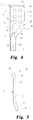
- Locking member 66 includes an intermediate portion 74 positioned between a proximal end portion 68 and a distal end portion 70. As illustrated in FIG. 5 for example, proximal end portion 68 and distal end portion 70 are angled relative to intermediate portion 74 such that proximal end portion 68 extends in a first direction from intermediate portion 74 and is laterally offset from distal end portion 70 which extends in a second direction from intermediate portion 74. Proximal end portion 68 and distal end portion 70 each includes a flat portion 76, 78, respectively, with flat portion 78 being larger than flat portion 76. Intermediate portion 74 includes an opening 72 extending through locking member 66.
- opening 72 When locking member 66 is positioned in internal chamber 56, opening 72 is generally aligned with passages 52, 54 to define a passageway through which elongate support member 12 can be positioned, as illustrated in FIG. 1 for example. With further reference to FIG. 5 for example, opening 72 is continuously enclosed by the surrounding portions of intermediate portion 74. In this configuration, opening 72 circumscribes elongate support member 12 when it is positioned in the passageway defined by opening 72 and passages 52, 54. As also illustrated in FIG. 5 for example, opening 72 includes a leading edge 80 which is engageable with proximal surface 15 of elongate support member 12 when it is positioned through opening 72, further details of which will be provided below.
- Internal chamber 56 extends from proximal end 34 of external housing 32 to a distal portion 58. While not illustrated, it should be appreciated that a cover can be provided to enclose internal chamber 56 at proximal end 34.
- Distal portion 58 includes a receptacle 60 positioned between lateral sidewalls 38, 40 and sized and structured to receive distal end portion 70 of locking member 66. When positioned in receptacle 60, distal end portion 70 is generally restrained from lateral movement in internal chamber 56.
- a transverse bore 62 extends through lateral sidewall 38 into communication with receptacle 60 and terminates at end wall 63. As illustrated in the assembly view of FIG.
- a compressible biasing member 82 in the form of coil spring 84 is positioned in transverse bore 62 and is compressed between locking member 66 and external housing 32. More particularly, a first end of spring 84 engages with end wall 63 of bore 62 and a second end of spring 84 engages with flat portion 78 of distal end portion 70 of locking member 66.
- biasing member 82 may be alternatively configured such as, for example, a leaf spring, a split washer or a compressible polymer of elastic member, just to name a few possibilities.
- First arm member 30 also includes a release button 88 that includes a user engagement portion 90 and an enlarged flange 92. Release button 88 is positionable in bore 64 which extends through lateral sidewall 38 into communication with internal chamber 56.
- user engagement portion 90 can extend through bore 64 with enlarged flange 92 positioned against the interior surface of lateral sidewall 38. Enlarged flange portion 92 is also engageable with flat portion 76 of proximal end portion 68 of locking member 66.
- release button 88 can be depressed by a user into engagement with locking member 66, moving proximal end portion 68 toward lateral sidewall 40. As a result, leading edge 80 of opening 72 becomes disengaged from proximal side 15 of elongate support member 12 and first arm member 30 is freely movable along elongate support member 12.
- a biasing mechanism can be utilized that positions release button 88 in an extended configuration (illustrated in FIG.
- release button 88 could be interconnected with locking member 66, utilizing for example, a threaded interconnection. Still, in yet another form it is contemplated that release button 88 could be integrally formed with locking member 66.
- biasing member 82 is replaced by a biasing member positioned in internal chamber 56 between proximal end portion 68 of locking member 66 and lateral sidewall 40.
- the biasing member directly applies a biasing force against proximal end portion 68 and forces proximal end portion 68 toward lateral sidewall 38.
- the biasing member can be compressed when release button 88 is depressed by a user to facilitate disengagement of locking member 66 from proximal surface 15 of elongate support member 12 so that first arm member 30 can be freely moved along elongate support member 12.
- External housing 32 also defines an elongated, internal receptacle 94 extending from distal end 36 to a proximal end portion 96.
- Proximal end portion 96 is positioned distally of distal portion 58 of internal chamber 56 and is reduced in size relative to the remainder of receptacle 94, thereby providing an enlarged shoulder portion 98 in receptacle 94 adjacent to proximal end portion 96.
- First arm member 30 further includes an elongated pin 102 having a cylindrical body extending between a proximal end 103 positionable in proximal end portion 96 and an opposite distal end 104. Elongated pin 102 includes transverse bore 107 adjacent to proximal end 103.
- transverse bore 107 is aligned with bore 101 which extends through lateral sidewalls 38, 40 of external housing 32.
- a cross pin 108 can be inserted through bores 101, 107 to couple elongated pin 102 with first arm member 30.
- First arm member 30 also includes a compressible biasing member 109 in the form of coil spring 110 and a first spline member 113, each of which includes an axial bore and is positionable over elongated pin 102 in receptacle 94.
- biasing member 109 may be alternatively configured such as, for example, a leaf spring, a split washer or a compressible polymer of elastic member, just to name a few possibilities. Further details of biasing member 109 and first spline member 113 will be provided below.
- a second spline member 120 is also provided and includes an axial bore structured to receive and engage with distal end 104 of pin elongated 102.
- Second spline member 120 is also engageable with a proximal internal receptacle (not shown) of engagement portion 46. More particularly, elongated pin 102 includes an annular groove 106 adjacent to distal end 104 which aligns with bore 124 of spline member 120 when elongated pin 102 is positioned in the axial bore thereof. Further, when spline member 120 is positioned in the proximal internal receptacle of engagement portion 46, annular groove 106, bore 124 and bore 128, which extends through engagement portion 46, are all aligned. A cross pin 129 can be inserted through bores 124, 128 and across annular groove 106 to couple engagement portion 46, spline member 120 and elongated pin 102.
- bores 124, 128 are offset from the center of engagement portion 46 and spline member 120, respectively, to allow cross pin 108 to extend across annular groove 106.
- engagement portion 46 is free to rotate about distal end 104 of elongated pin 102.
- ball member 127 and spring 126 should be assembled with engagement portion 46 before engagement portion 46, spline member 120 and elongated pin 102 are coupled together. More particularly, ball member 127 is positioned in an opening (not shown) between the proximal internal receptacle of engagement portion 46 and recess 48. The opening should be appropriately sized to allow a portion of ball member 127 to protrude into recess 48 while preventing ball member 127 from entirely passing into recess 48 from the proximal internal receptacle. Once ball member 127 is appropriately positioned, one end of spring 126 is positioned into engagement therewith.
- spring 126 extends through an opening 125 in distal end 122 of spline member 120 and engages with distal end 104 of elongated pin 102 when engagement portion 46, spline member 120 and elongated pin 102 are coupled together.
- the engagement between spring 126 and elongated pin 102 compresses spring 126 and distally biases ball member 127 as described herein above.
- spring 126 has a tapered configured and its proximal end engages with distal end 122 of spline member 120 instead of distal end 104 of elongated pin 102.
- engagement portion 46, spline member 120 and elongated pin 102 are first coupled together with cross pin 129.
- Spline member 113 and biasing member 109 are then placed over elongated pin 102 and elongated pin 102 is inserted into receptacle 94 until proximal end 103 engages with proximal end portion 96.
- cross pin 108 can be inserted through bores 101 and 107 to couple elongated pin 102 with external housing 32.
- spring 110 becomes compressed between shoulder portion 96 of receptacle 94, which engages with proximal end 111 of spring 110, and proximal end 114 of spline member 113, which engages with distal end 112 of spring 110, thereby distally biasing spline member 113 into engagement with spline member 120.
- hole 116 of spline member 113 is aligned with slot 100 extending through external housing 32 and release button 118 is engaged therewith. More particularly, release button 118 includes a stem 119 which extends through slot 100 and into engagement with hole 116.
- release button 118 prevents spline member 113 from rotating about elongated pin 102.
- spline member 113 serves as a locking element which limits the rotation of engagement portion 46 about elongated pin 102, further details of which will be provided below with respect to FIGS. 6-7 .
- release button 118 can be engaged by a user to compress spring 118 and disengage spline member 113 from spline member 120 to allow engagement portion 46 to rotate freely about elongated pin 102.
- spline member 120 will generally be coupled with engagement portion 46 when it interacts with spline member 113. Accordingly, the rotational movements described with respect to spline member 120 will correspond to those of engagement portion 46 relative to external housing 32.
- Distal end 115 of spline member 113 includes a plurality of teeth 117 which are structured to interdigitate and engage with a plurality of teeth 123 positioned on proximal end 121 of spline member 120. As illustrated in FIG.
- teeth 117 and 123 engage with one another spline member 120 is allowed to rotate in a first direction but is prevented from rotating in an opposite, second direction. More particularly, teeth 123 of spline member 120 slip past teeth 117 of spline member 113 when spline member 120 is rotated in the direction indicated by directional arrow R 1 , which corresponds to a clockwise direction, and spline member 120 is allowed to rotate freely in this direction relative to external housing 32. However, if a rotational force is applied to spline member 120 in the direction opposite of that indicated by directional arrow R 1 , a counterclockwise direction, teeth 123 interlock with teeth 117 and prevent rotation of spline member 120 in such direction relative to external housing 32. Once spline member 113 is disengaged from spline member 120, spline member 120 is able to rotate freely about elongated pin 102.
- Second arm member 130 includes spline members 213, 220 which are arranged differently from spline members 113, 120 described and illustrated with respect to first arm member 30. More particularly, with reference to FIG. 7 , an enlarged plan view of spline members 213, 220 is provided. While not illustrated, it should be appreciated that spline member 220 will generally be engaged with engagement portion 146 when it interacts with spline member 213. Accordingly, the rotational movements described with respect to spline member 220 will correspond to those of engagement portion 146 relative to external housing 132.
- Distal end 215 of spline member 213 includes a plurality of teeth 217 which are structured to interdigitate and engage with a plurality of teeth 223 positioned on proximal end 221 of spline member 220. As illustrated in FIG. 7 , when teeth 217 and 223 engage with one another, spline member 220 is allowed to rotate in a first direction but is prevented from rotating in an opposite, second direction.
- teeth 223 of spline member 220 slip past teeth 217 of spline member 213 when spline member 220 is rotated in the direction indicated by directional arrow RR 1 , which corresponds to a counter-clockwise direction, and spline member 220 is allowed to rotate freely in this direction relative to external housing 132.
- teeth 223 interlock with teeth 217 and prevent rotation of spline member 220 in such direction relative to external housing 132.
- assembly 10 is configured such that first and second retractor blades 302, 342 can be pivoted or rotated toward one another about their first ends 304, 344 to provide working channel 390 with a tapered configuration that reduces in size from the second ends 306, 346 of retractor blades 302, 342 through the skin to the first ends 304, 344 of retractor blades 302, 342. More particularly, when engagement portion 46 is rotated clockwise and engagement portion 146 is rotated counter-clockwise, a separation distance between second ends 306, 346 of retractor blades 302, 342 is increased.
- the engagement between teeth 113, 213 and teeth 123, 223 of spline members 113, 213 and 120, 220 allows a user to incrementally rotate engagement portions 46, 146 and increase the separation distance between second ends 306, 346 of retractor blades 302, 342.
- release buttons 118, 218 are depressed by a user, the biasing of spline members 113, 213 into engagement with spline members 120, 220 prevents rotation of engagement portions 46, 146 in opposite directions and reduction of the separation distance between second ends 306, 346 of retractor blades 302, 342, thereby providing a desired configuration of working channel 390 for the duration of the surgical procedure.
- a tapered working channel provides the surgeon greater access and increased visualization of the surgical site while minimizing tissue retraction.
- the tapered working channel 390 also allows greater angulation of instruments and implants placed through working channel 390, more selection in positioning of instruments and implants within working channel 390, and the ability to position instruments and implants adjacent the inner wall surfaces of the separated first and second retractor blades 302, 342, increasing the room available at the surgical site for multiple instruments and for orienting implants.
- Springs 84, 184 engage with the distal end portions of locking members 66, 166 and bias the distal end portions of locking members 66, 166 toward first end 16 and second end 18, respectively, of elongate support member 12. Additionally, the proximal end portions of locking members 66, 166 are biased toward first end 16 and second end 18, respectively, of elongate support member 12, thereby advancing leading edges 80, 180 into engagement with teeth 28 on proximal surface 15 of elongate support member 12.
- first arm member 30 is only movable toward first end 16 of elongate support member 12, as indicated by directional arrow 400, and second arm member 130 is only movable toward second end 18 of elongate support member 12, as indicated by directional arrow 402.
- first arm member 30 and second arm member 130 away from one another as illustrated in FIG. 8 facilitates enlargement of working channel 390 between retractor portions 300, 340.
- the engagement between arm members 30, 130 and elongate support member 12 allows a user to incrementally enlarge working channel 390 until a desired configuration is provided. Once a desired configuration of working channel 390 between retractor portions 300, 340 has been achieved, the engagement between leading edges 80, 180 and proximal surface 15 of elongate support member 12 retains working channel 390 in the desired configuration until the surgical procedure is complete. It should be appreciated that assembly 10 is operable to retain working channel 390 in the desired configuration without the use of additional instrumentation.
- arm members 30, 130 can be moved along elongate support member 12 by a health care professional to enlarge working channel 390.
- one or more separation instruments can be coupled to arm members 30, 130 or distractor portions 300, 340 to enlarge working channel 390.
- the separation instrument can be coupled between retractor portions 302, 342.
- Various non-limiting examples of separation instruments are provided in U.S. Patent Publication No. 2004/0176665 to Branch et al.
- engagement portions 46, 146 are limited to rotation in the clockwise and counter-clockwise directions, as indicated by directional arrows R 1 and RR 1 , respectively, and can be rotated to increase the separation distance between second ends 306, 346 of retractor blades 302, 342 and provide a tapered working channel 390.
- a user can engage one or both of engagement portions 46, 146 and retractor portions 300, 340 to facilitate rotation of engagement portions 46, 146 along axes A, AA, respectively.
- one or more instruments can be coupled to engagement portions 46, 146 or distractor portions 300, 340 to rotate engagement portions 46, 146 about axes A, AA.
- arm members 30, 130 can be moved toward one another to reduce the size of working channel 390 to facilitate removal or repositioning of retractor portions 300, 340 at the surgical site. More particularly, as illustrated in FIG. 9 , release buttons 88, 188 can be depressed as indicated by directional arrows 404, 406, respectively, thereby disengaging leading edges 80, 180 from engagement with proximal surface 15 of elongate support member 12 and allowing arm members 30, 130 to move freely along elongate support member 12 as indicated by directional arrows 408, 410, respectively.
- release buttons 118, 218 can be moved proximally as indicated by directional arrows 412, 414, respectively, thereby facilitating rotation of engagement portions 46, 146 in clockwise and counter-clockwise directions about axes A, AA, as indicated by directional arrows R 2 , RR 2 . Accordingly, any tapered configuration of working channel 390 can be released to facilitate removal or repositioning of retractor portions 300, 340 at the surgical site, or the tapered configuration can be reconfigured.
- an assembly for percutaneous surgery in a patient includes an elongate support member extending between a first end and an opposite second end.
- the assembly also includes a first arm member positionable along the elongate support member.
- the first arm member includes an external housing extending between a proximal end including a passage sized and structured to receive the elongate support member and a distal end structured to engage with a first retractor portion.
- the external housing defines an internal chamber and the first arm member includes a first locking member positioned in the internal chamber.
- the assembly also includes a second arm member positionable along the elongate support member.
- the second arm member includes an external housing extending between a proximal end including a passage sized and structured to receive the elongate support member and a distal end structured to engage with a second retractor portion.
- the external housing defines an internal chamber and the second arm member includes a second locking member positioned in the internal chamber.
- the elongate support member extends through an opening in each of the first and second locking members when the first and second arm members are positioned on the elongate support member.
- the first and second locking members are biased into engagement with the elongate support member, with the engagement between the first and second locking members and the elongate support member controlling movement of the first and second arm members along the elongate support member.
- an assembly for percutaneous surgery in a patient includes an elongate support member extending between a first end and an opposite second end.
- the assembly further includes a pair of arm members removably positioned on and movable along the elongate support member and engageable with a respective retractor portion.
- the arm members each include a passageway extending through an external housing and a locking member positioned in the external housing and the elongate support member extends through the passageway. Furthermore, the locking member of each of the arm members is releasably biased into engagement with the elongate support member.
- the engagement between the locking members and the elongate support member allows movement of the arm members along the elongate support member in opposite directions toward the first and second ends of the elongate support member and prevents movement of the arm members along the elongate support member toward one another.
- an assembly for percutaneous surgery in a patient includes an elongate support member extending between a first end and an opposite second end.
- the assembly also includes a first arm member including an external housing extending along a longitudinal axis between a proximal end engageable with the elongate support member and an opposite distal end.
- the distal end includes a first engagement portion rotatably coupled to the first arm member and structured to engage with a first retractor portion.
- the assembly further includes a second arm member including an external housing extending along a longitudinal axis between a proximal end engageable with the elongate support member and an opposite distal end.
- the distal end includes a second engagement portion rotatably coupled to the second arm member and structured to engage with a second retractor portion.
- the external housing of each of the first and second arm members defines an elongated receptacle extending along the longitudinal axis from a distal opening at the distal end.
- the elongated receptacle includes a locking element releasably biased into engagement with a respective engagement portion. The engagement between the locking element and the respective engagement portion allows rotation of the engagement portion in a first direction about the longitudinal axis of a respective arm member and prevents rotational movement of the engagement portion in a second direction about the longitudinal axis of the respective arm member.
- an assembly for percutaneous surgery in a patient includes an elongate support member extending between a first end and an opposite second end.
- the assembly also includes an arm member positionable along the elongate support member.
- the arm member includes an external housing extending between a proximal end including a passage sized and structured to receive the elongate support member and a distal end structured to engage with a retractor portion.
- the external housing defines an internal chamber and the arm member includes a locking member positioned in the internal chamber.
- the elongate support member extends through an opening in the locking member when the arm member is positioned on the elongate support member. The locking member is biased into engagement with the elongate support member, with the engagement between the locking member and the elongate support member controlling movement of the arm member along the elongate support member.
- an assembly for percutaneous surgery in a patient includes an elongate support member extending between a first end and an opposite second end.
- the assembly also includes an arm member including an external housing extending along a longitudinal axis between a proximal end engageable with the elongate support member and an opposite distal end.
- the distal end includes an engagement portion rotatably coupled to the arm member and structured to engage with a retractor portion.
- the external housing of the arm member defines an elongated receptacle extending along the longitudinal axis from a distal opening at the distal end.
- the elongated receptacle includes a locking element releasably biased into engagement with the engagement portion. The engagement between the locking element and the engagement portion allows rotation of the engagement portion in a first direction about the longitudinal axis of the arm member and prevents rotational movement of the engagement portion in a second direction about the longitudinal axis of the arm member.
Landscapes
- Health & Medical Sciences (AREA)
- Life Sciences & Earth Sciences (AREA)
- Surgery (AREA)
- Nuclear Medicine, Radiotherapy & Molecular Imaging (AREA)
- Molecular Biology (AREA)
- Veterinary Medicine (AREA)
- Public Health (AREA)
- General Health & Medical Sciences (AREA)
- Animal Behavior & Ethology (AREA)
- Engineering & Computer Science (AREA)
- Biomedical Technology (AREA)
- Heart & Thoracic Surgery (AREA)
- Medical Informatics (AREA)
- Physics & Mathematics (AREA)
- Biophysics (AREA)
- Radiology & Medical Imaging (AREA)
- Pathology (AREA)
- Optics & Photonics (AREA)
- Surgical Instruments (AREA)
Claims (8)
- Ensemble (10) de chirurgie sur un patient, comprenant :un élément de support allongé (12) s'étendant entre une première extrémité (16) et une deuxième extrémité opposée (18) ;un premier élément de bras (30) incluant un logement externe (32) s'étendant le long d'un axe longitudinal entre une extrémité proximale pouvant venant en prise avec ledit élément de support allongé et une extrémité distale opposée, ladite extrémité distale incluant une première partie de prise (46) couplée en rotation avec ledit premier élément de bras et structurée pour venir en prise avec une première partie d'écarteur (302) ;un deuxième élément de bras (130) incluant un logement externe (132) s'étendant le long d'un axe longitudinal entre une extrémité proximale pouvant venant en prise avec ledit élément de support allongé et une extrémité distale opposée, ladite extrémité distale incluant une deuxième partie de prise (146) couplée en rotation avec ledit deuxième élément de bras et structurée pour venir en prise avec une deuxième partie d'écarteur (342) ;dans lequel ledit logement externe de chacun desdits premier et deuxième éléments de bras définit un réceptacle allongé s'étendant le long dudit axe longitudinal à partir d'une ouverture distale au niveau de ladite extrémité distale, ledit réceptacle allongé incluant un élément de verrouillage rappelé en prise de manière détachable avec une partie de prise respective ;une première partie d'écarteur (302) incluant une première extrémité en prise avec ladite première partie de prise et une deuxième extrémité (306) positionnable dans une incision : etune deuxième partie d'écarteur (342) incluant une première extrémité en prise avec ladite deuxième partie de prise et une deuxième extrémité (346) positionnable dans l'incision face à ladite deuxième extrémité de ladite première partie d'écarteur ; caractérisé en ce que ladite prise entre ledit élément de verrouillage et ladite partie de prise respective permet une rotation de ladite partie de prise dans une première direction par rapport à l'axe longitudinal d'un élément de bras respectif et empêche le mouvement de rotation de ladite partie de prise dans une deuxième direction par rapport à l'axe longitudinal dudit élément de bras respectif ; eten ce que la rotation desdites première et deuxième parties de prise par rapport auxdits axes longitudinaux desdits premier et deuxième éléments de bras dans lesdites premières directions respectives (Ri, RRi) augmente une distance de séparation entre lesdites deuxièmes extrémités desdites première et deuxième parties d'écarteur.
- Ensemble (10) selon la revendication 1, dans lequel :lesdits premier et deuxième éléments de bras (30, 130) incluent chacun un élément cylindrique allongé s'étendant à distance de ladite ouverture distale à partir d'une partie proximale dudit réceptacle allongé ; etlesdites première et deuxième parties de prise définissent chacune un évidement interne recevant une extrémité distale d'un élément cylindrique allongé respectif.
- Ensemble (10) selon la revendication 1, dans lequel :
ledit élément de verrouillage est rappelé en prise de manière détachable avec une partie de prise respective par un ressort hélicoïdal (110). - Ensemble (10) selon la revendication 1, dans lequel :
ledit élément de verrouillage et la partie de prise respective comprennent une pluralité de dents. - Ensemble (10) selon la revendication 1, dans lequel :lesdits premier et deuxième éléments de bras (20, 130) incluent chacun un passage s'étendant à travers un logement externe et un élément de verrouillage positionné dans ledit logement externe, ledit élément de support allongé s'étendant à travers ledit passage ; etdans lequel ledit élément de verrouillage (66) de chacun desdits éléments de bras est rappelé en prise de manière détachable avec ledit élément de support allongé (112), ladite prise entre lesdits éléments de verrouillage et ledit élément de support allongé (112) permettant un déplacement desdits éléments de bras le long dudit élément de support allongé (12) dans des directions opposées vers lesdites première et deuxième extrémités (16, 18) dudit élément de support allongé (12) et empêchant un déplacement desdits éléments de bras le long dudit élément de support allongé (12) l'un vers l'autre.
- Ensemble (10) selon la revendication 5, dans lequel ledit élément de support allongé (12) s'étend à travers une ouverture dans chacun desdits premier et deuxième éléments de verrouillage quand lesdits premier et deuxième éléments de bras (30, 130) sont positionnés sur ledit élément de support allongé (12).
- Ensemble (10) selon la revendication 6, dans lequel ledit logement externe de chacun desdits premier et deuxième éléments de bras (30, 130) définit un réceptacle dans ladite chambre interne respective, lesdits premier et deuxième éléments de verrouillage incluant chacun une partie d'extrémité proximale positionnée adjacente à ladite extrémité proximale dudit logement externe et une partie d'extrémité distale positionnée dans ledit réceptacle.
- Ensemble (10) selon la revendication 7, dans lequel :ledit élément de support allongé (12) inclut une pluralité de dents (28) positionnées le long d'une surface proximale de celui-ci, ladite pluralité de dents (28) étant mises en prise par une partie d'une paroi latérale interne définissant ladite ouverture desdits premier et deuxième éléments de verrouillage respectifs ; etladite prise entre lesdits premier et deuxième éléments de verrouillage et ledit élément de support allongé permet le déplacement desdits premier et deuxième éléments de bras dans des directions opposées le long dudit élément de support allongé vers lesdites première et deuxième extrémités dudit élément de support allongé et empêche le déplacement desdits premier et deuxième éléments de bras le long dudit élément de support allongé l'un vers l'autre.
Applications Claiming Priority (3)
| Application Number | Priority Date | Filing Date | Title |
|---|---|---|---|
| US12/262,100 US8226554B2 (en) | 2008-10-30 | 2008-10-30 | Retractor assemblies for surgery in a patient |
| EP09827979.7A EP2344046A4 (fr) | 2008-10-30 | 2009-10-29 | Écarteurs chirurgicaux |
| PCT/US2009/062601 WO2010059383A2 (fr) | 2008-10-30 | 2009-10-29 | Écarteurs chirurgicaux |
Related Parent Applications (1)
| Application Number | Title | Priority Date | Filing Date |
|---|---|---|---|
| EP09827979.7A Division EP2344046A4 (fr) | 2008-10-30 | 2009-10-29 | Écarteurs chirurgicaux |
Publications (2)
| Publication Number | Publication Date |
|---|---|
| EP3178409A1 EP3178409A1 (fr) | 2017-06-14 |
| EP3178409B1 true EP3178409B1 (fr) | 2018-08-22 |
Family
ID=42132262
Family Applications (2)
| Application Number | Title | Priority Date | Filing Date |
|---|---|---|---|
| EP17151651.1A Active EP3178409B1 (fr) | 2008-10-30 | 2009-10-29 | Ensembles de rétracteur pour intervention chirurgicale chez un patient |
| EP09827979.7A Withdrawn EP2344046A4 (fr) | 2008-10-30 | 2009-10-29 | Écarteurs chirurgicaux |
Family Applications After (1)
| Application Number | Title | Priority Date | Filing Date |
|---|---|---|---|
| EP09827979.7A Withdrawn EP2344046A4 (fr) | 2008-10-30 | 2009-10-29 | Écarteurs chirurgicaux |
Country Status (7)
| Country | Link |
|---|---|
| US (1) | US8226554B2 (fr) |
| EP (2) | EP3178409B1 (fr) |
| JP (1) | JP5406932B2 (fr) |
| KR (1) | KR20110081882A (fr) |
| CN (1) | CN102202581B (fr) |
| AU (2) | AU2009317968A1 (fr) |
| WO (1) | WO2010059383A2 (fr) |
Families Citing this family (55)
| Publication number | Priority date | Publication date | Assignee | Title |
|---|---|---|---|---|
| US9795367B1 (en) | 2003-10-17 | 2017-10-24 | Nuvasive, Inc. | Surgical access system and related methods |
| US20080255567A1 (en) * | 2007-04-10 | 2008-10-16 | Joseph Accordino | Spinal distraction system |
| US9307971B2 (en) * | 2010-02-01 | 2016-04-12 | Warsaw Orthopedic, Inc. | Surgical retractor instrument systems and methods of using the same |
| US11998184B2 (en) | 2010-03-11 | 2024-06-04 | Globus Medical, Inc | Tissue retractor and methods of use |
| US9179903B2 (en) | 2010-03-11 | 2015-11-10 | Globus Medical, Inc. | Tissue retractor and method of use |
| US8353826B2 (en) * | 2010-03-11 | 2013-01-15 | Globus Medical, Inc. | Tissue retractor and method of use |
| US9861273B2 (en) | 2010-03-11 | 2018-01-09 | Globus Medical, Inc. | Tissue retractor and method of use |
| US9737288B2 (en) | 2010-03-11 | 2017-08-22 | Globus Medical, Inc | Tissue retractor and methods of use |
| US8968363B2 (en) * | 2010-03-11 | 2015-03-03 | Globus Medical, Inc. | Tissue retractor and methods of use |
| CN103167825B (zh) | 2010-08-23 | 2016-06-22 | 纽文思公司 | 外科入路系统及相关方法 |
| WO2012048337A1 (fr) * | 2010-10-08 | 2012-04-12 | K2M, Inc. | Système d'accès latéral et procédé d'utilisation |
| FR2971410B1 (fr) * | 2011-02-14 | 2013-03-15 | Assist Publ Hopitaux De Paris | Speculum vaginal a quatre valves |
| US20120259177A1 (en) * | 2011-04-05 | 2012-10-11 | Warsaw Orthopedic, Inc. | Overlapping Retractor Blade Assemblies |
| US20120271119A1 (en) * | 2011-04-19 | 2012-10-25 | NSI-US, Inc. | Auto-locking surgical retractor assembly |
| US9277906B2 (en) * | 2011-04-19 | 2016-03-08 | NSI-US, Inc. | Quick-release handle for retractor blades |
| US8900137B1 (en) | 2011-04-26 | 2014-12-02 | Nuvasive, Inc. | Cervical retractor |
| US8974381B1 (en) | 2011-04-26 | 2015-03-10 | Nuvasive, Inc. | Cervical retractor |
| WO2013028571A1 (fr) | 2011-08-19 | 2013-02-28 | Lanx, Inc. | Système d'écarteur chirurgical et procédés d'utilisation |
| US9113853B1 (en) | 2011-08-31 | 2015-08-25 | Nuvasive, Inc. | Systems and methods for performing spine surgery |
| WO2013044151A1 (fr) | 2011-09-23 | 2013-03-28 | Invuity, Inc. | Écarteur de tissus mous modulaire avec éclairage |
| JP2014533136A (ja) | 2011-10-05 | 2014-12-11 | マーク・エイ・ドッドソン | モジュール開創器および関連する方法 |
| US9592041B2 (en) * | 2011-10-18 | 2017-03-14 | Warsaw Orthopedic, Inc. | Surgical retractor assembly and method |
| US9301674B2 (en) * | 2011-11-14 | 2016-04-05 | Biomet Manufacturing, Llc | Self-retaining retractor |
| CN102525577B (zh) * | 2012-01-30 | 2013-10-23 | 上海拓腾医疗器械有限公司 | 微创手术撑开器及撑开装置 |
| US9066701B1 (en) | 2012-02-06 | 2015-06-30 | Nuvasive, Inc. | Systems and methods for performing neurophysiologic monitoring during spine surgery |
| US9655505B1 (en) | 2012-02-06 | 2017-05-23 | Nuvasive, Inc. | Systems and methods for performing neurophysiologic monitoring during spine surgery |
| EP2705799B1 (fr) * | 2012-09-06 | 2015-05-13 | Medacta International S.A. | Dispositif chirurgical pour soudure spinale minimalement invasive et système chirurgical comprenant celui-ci |
| US9084591B2 (en) * | 2012-10-23 | 2015-07-21 | Neurostructures, Inc. | Retractor |
| US9757067B1 (en) | 2012-11-09 | 2017-09-12 | Nuvasive, Inc. | Systems and methods for performing neurophysiologic monitoring during spine surgery |
| US10039539B2 (en) | 2014-02-18 | 2018-08-07 | Globus Medical, Inc. | Retracting tissue |
| US10285680B2 (en) * | 2014-02-18 | 2019-05-14 | Globus Medical, Inc. | Retracting tissue |
| US10278786B2 (en) | 2014-02-18 | 2019-05-07 | Globus Medical, Inc. | Retracting tissue |
| US9724137B2 (en) * | 2014-03-19 | 2017-08-08 | Warsaw Orthopedic, Inc. | Surgical instrumentation and method |
| GB2543468B (en) | 2014-08-13 | 2021-11-03 | Nuvasive Inc | Minimally disruptive retractor and associated methods for spinal surgery |
| US10111712B2 (en) | 2014-09-09 | 2018-10-30 | Medos International Sarl | Proximal-end securement of a minimally invasive working channel |
| US10264959B2 (en) | 2014-09-09 | 2019-04-23 | Medos International Sarl | Proximal-end securement of a minimally invasive working channel |
| WO2016081403A1 (fr) * | 2014-11-18 | 2016-05-26 | DePuy Synthes Products, Inc. | Fixation de l'extrémité proximale d'un canal de travail à invasivité minimale |
| US9848863B2 (en) | 2015-02-25 | 2017-12-26 | Globus Medical, Inc | Surgical retractor systems and methods |
| US9681899B2 (en) | 2015-03-23 | 2017-06-20 | Globus Medical, Inc. | Orthopedic derotation devices and methods of installation thereof |
| US11602379B2 (en) | 2015-03-23 | 2023-03-14 | Globus Medical, Inc. | Orthopedic derotation devices and methods of installation thereof |
| US9700293B2 (en) | 2015-08-18 | 2017-07-11 | Globus Medical, Inc. | Devices and systems for surgical retraction |
| DE102016104531A1 (de) * | 2016-03-11 | 2017-09-14 | Max Hauser Süddeutsche Chirurgiemechanik GmbH | Spreizvorrichtung zum Aufdehnen und Offenhalten von natürlichen oder geschaffenen Körperöffnungen |
| US10624622B2 (en) * | 2016-04-19 | 2020-04-21 | Worcester Polytechnic Institute | Surgical retraction device |
| US10786328B2 (en) * | 2016-10-26 | 2020-09-29 | Thompson Surgical Instruments, Inc. | Adaptor handle for surgical retractor |
| DE102016122593A1 (de) | 2016-11-23 | 2018-05-24 | Biowim Products Gmbh | Instrument zum Dehnen der Haut |
| ES2871543T3 (es) * | 2018-01-26 | 2021-10-29 | Aesculap Ag | Instrumento de reposicionamiento espinal y sistema de reposicionamiento espinal |
| MX2020008581A (es) | 2018-02-21 | 2020-09-21 | Bristol Myers Squibb Co | Oligonucleotidos antisentido de la proteina cinasa del tipo ii delta dependiente del calcio/calmodulina (camk2d) y sus usos. |
| US10660631B1 (en) * | 2018-12-13 | 2020-05-26 | Invictus Development & Engineering, Inc. | Pedicle screw mounted retractor system |
| US10959716B2 (en) * | 2019-02-11 | 2021-03-30 | Warsaw Orthopedic, Inc. | Surgical retractor system and method |
| KR102348007B1 (ko) * | 2019-10-24 | 2022-01-07 | 인제대학교 산학협력단 | 압력 표시 견인기 |
| USD956225S1 (en) | 2020-05-12 | 2022-06-28 | Innovasis, Inc. | Surgical retractor |
| USD956224S1 (en) | 2020-05-12 | 2022-06-28 | Innovasis, Inc. | Surgical retractor |
| US11432810B2 (en) | 2020-05-12 | 2022-09-06 | Innovasis, Inc. | Systems and methods for surgical retraction |
| USD956223S1 (en) | 2020-05-12 | 2022-06-28 | Innovasis, Inc. | Surgical retractor |
| US20230248347A1 (en) * | 2022-02-10 | 2023-08-10 | Warsaw Orthopedic, Inc. | Surgical system and method |
Family Cites Families (123)
| Publication number | Priority date | Publication date | Assignee | Title |
|---|---|---|---|---|
| US563236A (en) * | 1896-06-30 | Speculum | ||
| US1400616A (en) * | 1921-01-10 | 1921-12-20 | Harvey B Mccrory | Abdominal retractor |
| US1613141A (en) * | 1923-05-26 | 1927-01-04 | Herbert E Stein | Surgical retractor instrument |
| FR1019217A (fr) | 1950-03-10 | 1953-01-19 | Perfectionnements apportés aux écarteurs chirurgicaux, notamment à ceux pour opérations endothoraciques | |
| US2693795A (en) * | 1950-09-09 | 1954-11-09 | Herman R Grieshaber | Surgical retractor |
| US2670731A (en) * | 1952-02-11 | 1954-03-02 | Zoll Carl Michael | Abdominal retractor attachment |
| US2661735A (en) * | 1952-07-28 | 1953-12-08 | Davis Rachel Darden | Speculum |
| US3054398A (en) * | 1961-02-13 | 1962-09-18 | Arnold J Kobler | Eyelid spreader |
| US3227156A (en) * | 1962-12-04 | 1966-01-04 | William K Gauthier | Abdominal retractor device |
| US3747592A (en) * | 1970-06-30 | 1973-07-24 | M Santos | Multiply adjustable surgical retractor |
| US3752149A (en) * | 1971-12-16 | 1973-08-14 | L Ungar | Vaginal speculum |
| US3788318A (en) * | 1972-06-12 | 1974-01-29 | S Kim | Expandable cannular, especially for medical purposes |
| US3965890A (en) * | 1974-10-18 | 1976-06-29 | William Kohlmann Gauthier | Surgical retractor |
| US4156424A (en) * | 1978-05-01 | 1979-05-29 | Burgin Kermit H | Locking adjustable speculum |
| US4380999A (en) * | 1980-07-15 | 1983-04-26 | Healy Keelin E | Stepped surgical retractor |
| US4545374A (en) * | 1982-09-03 | 1985-10-08 | Jacobson Robert E | Method and instruments for performing a percutaneous lumbar diskectomy |
| GB8424436D0 (en) * | 1984-09-27 | 1984-10-31 | Pratt Int Ltd Burnerd | Surgical appliance |
| GB8513702D0 (en) * | 1985-05-30 | 1985-07-03 | Gill S S | Expansible trocar |
| SU1459658A1 (ru) * | 1986-04-24 | 1989-02-23 | Благовещенский государственный медицинский институт | Ранорасширитель |
| US4747394A (en) * | 1986-10-08 | 1988-05-31 | Watanabe Orthopedic Systems, Inc. | Spinal retractor |
| DE8704901U1 (de) | 1987-04-02 | 1987-07-23 | Kluger, Patrick, Dr.med., 3590 Bad Wildungen | Vorrichtung zum Einrichten einer Wirbelsäule mit geschädigten Wirbelkörpern |
| US4817587A (en) * | 1987-08-31 | 1989-04-04 | Janese Woodrow W | Ring para-spinal retractor |
| US4852552A (en) * | 1987-09-03 | 1989-08-01 | Pilling Co. | Sternal retractor |
| US4862891A (en) * | 1988-03-14 | 1989-09-05 | Canyon Medical Products | Device for sequential percutaneous dilation |
| US6120437A (en) | 1988-07-22 | 2000-09-19 | Inbae Yoon | Methods for creating spaces at obstructed sites endoscopically and methods therefor |
| US5052373A (en) * | 1988-07-29 | 1991-10-01 | Michelson Gary K | Spinal retractor |
| US5067477A (en) * | 1989-08-01 | 1991-11-26 | Codman & Shurtleff, Inc. | Low wear bearing for a surgical retractor |
| GB2240926A (en) * | 1990-02-14 | 1991-08-21 | Steven Streatfield Gill | An expansible cannula |
| US5163949A (en) * | 1990-03-02 | 1992-11-17 | Bonutti Peter M | Fluid operated retractors |
| US5197971A (en) * | 1990-03-02 | 1993-03-30 | Bonutti Peter M | Arthroscopic retractor and method of using the same |
| US5454365A (en) | 1990-11-05 | 1995-10-03 | Bonutti; Peter M. | Mechanically expandable arthroscopic retractors |
| US5514153A (en) | 1990-03-02 | 1996-05-07 | General Surgical Innovations, Inc. | Method of dissecting tissue layers |
| US5027793A (en) * | 1990-03-30 | 1991-07-02 | Boehringer Mannheim Corp. | Surgical retractor |
| US5088472A (en) * | 1990-04-04 | 1992-02-18 | Mehdi Fakhrai | Retractor |
| US5389080A (en) * | 1990-07-26 | 1995-02-14 | Yoon; Inbae | Endoscopic portal for use in endoscopic procedures and methods therefor |
| US5125396A (en) * | 1990-10-05 | 1992-06-30 | Ray R Charles | Surgical retractor |
| US5158545A (en) * | 1991-05-02 | 1992-10-27 | Brigham And Women's Hospital | Diameter expansion cannula |
| US5217451A (en) * | 1991-05-24 | 1993-06-08 | Dexide, Inc. | Gear activated trocar assembly |
| CA2110695A1 (fr) * | 1991-06-06 | 1992-12-07 | Victor Manuel Pracas | Speculum |
| US5490819A (en) * | 1991-08-05 | 1996-02-13 | United States Surgical Corporation | Articulating endoscopic surgical apparatus |
| US5312417A (en) * | 1992-07-29 | 1994-05-17 | Wilk Peter J | Laparoscopic cannula assembly and associated method |
| US5299563A (en) * | 1992-07-31 | 1994-04-05 | Seton Joseph Z | Method of using a surgical retractor |
| US5961499A (en) | 1993-02-04 | 1999-10-05 | Peter M. Bonutti | Expandable cannula |
| US5320611A (en) * | 1993-02-04 | 1994-06-14 | Peter M. Bonutti | Expandable cannula having longitudinal wire and method of use |
| US5674240A (en) * | 1993-02-04 | 1997-10-07 | Peter M. Bonutti | Expandable cannula |
| CN2154663Y (zh) * | 1993-02-27 | 1994-02-02 | 中国人民解放军第二五四医院 | 带灯自动脊柱牵开器 |
| US5431676A (en) | 1993-03-05 | 1995-07-11 | Innerdyne Medical, Inc. | Trocar system having expandable port |
| US5353784A (en) * | 1993-04-02 | 1994-10-11 | The Research Foundation Of Suny | Endoscopic device and method of use |
| US5339803A (en) * | 1993-04-13 | 1994-08-23 | Ilya Mayzels | Self-hinging disposable retractor instrument for endoscopic surgery |
| US5512038A (en) * | 1993-11-15 | 1996-04-30 | O'neal; Darrell D. | Spinal retractor apparatus having a curved blade |
| US5620458A (en) * | 1994-03-16 | 1997-04-15 | United States Surgical Corporation | Surgical instruments useful for endoscopic spinal procedures |
| DE4415074C1 (de) * | 1994-04-29 | 1995-08-17 | Aesculap Ag | Chirurgisches Instrument |
| US6162236A (en) | 1994-07-11 | 2000-12-19 | Terumo Kabushiki Kaisha | Trocar needle and expandable trocar tube |
| US5503617A (en) | 1994-07-19 | 1996-04-02 | Jako; Geza J. | Retractor and method for direct access endoscopic surgery |
| US5807243A (en) | 1994-08-31 | 1998-09-15 | Heartport, Inc. | Method for isolating a surgical site |
| US5681265A (en) * | 1994-09-02 | 1997-10-28 | Yufu Seiki Co., Ltd. | Cylindrical anal retractor |
| US5795291A (en) * | 1994-11-10 | 1998-08-18 | Koros; Tibor | Cervical retractor system |
| US5667481A (en) * | 1995-02-01 | 1997-09-16 | Villalta; Josue J. | Four blade medical retractor |
| US6027518A (en) | 1995-05-30 | 2000-02-22 | Gaber; Benny | Seizing instrument |
| DE19522879A1 (de) * | 1995-06-23 | 1997-01-02 | Aesculap Ag | Chirurgischer Wundsperrer |
| US5616117A (en) * | 1995-08-03 | 1997-04-01 | Ohio Medical Instrument Company, Inc. | Self locking surgical retractor |
| GB9518888D0 (en) | 1995-09-15 | 1995-11-15 | Byrne Phillip O | Device and method for transcutaneous surgery |
| US5688223A (en) * | 1995-11-08 | 1997-11-18 | Minnesota Scientific, Inc. | Retractor support with adjustable retractor blades |
| US5707359A (en) * | 1995-11-14 | 1998-01-13 | Bufalini; Bruno | Expanding trocar assembly |
| CA2198036C (fr) | 1996-02-20 | 2000-12-05 | Charles S. Taylor | Plate-forme d'acces pour la dissection de l'artere thoracique interne |
| US6132370A (en) * | 1996-04-26 | 2000-10-17 | Genzyme Corporation | Retractor-mounted coronary stabilizer |
| US5776054A (en) * | 1996-08-07 | 1998-07-07 | Bobra; Dilip | Apparatus for retracting tissue |
| US6431025B1 (en) | 1996-08-30 | 2002-08-13 | Tibor Koros | Ratchet mechanism for a surgical retractor assembly |
| US5931778A (en) * | 1996-09-25 | 1999-08-03 | Genzyme Corporation | Rib retractor |
| US5785648A (en) * | 1996-10-09 | 1998-07-28 | David Min, M.D., Inc. | Speculum |
| US5865731A (en) | 1997-01-25 | 1999-02-02 | Lenox-Maclaren | Surgical retractor having variable position retractor blades |
| FR2758969B1 (fr) | 1997-02-04 | 1999-04-30 | Jean Paul Couetil | Ecarteur sternal ou ecarteur thoracique |
| EP1344495B1 (fr) | 1997-02-13 | 2008-10-08 | Boston Scientific Limited | Attache de suture à connection rapide |
| US5967972A (en) | 1997-03-28 | 1999-10-19 | Kapp Surgical Instrument, Inc. | Minimally invasive surgical retractor and method of operation |
| US5976146A (en) | 1997-07-11 | 1999-11-02 | Olympus Optical Co., Ltd. | Surgical operation system and method of securing working space for surgical operation in body |
| US6042540A (en) | 1997-08-18 | 2000-03-28 | Pacific Surgical Innovations, Inc. | Side-loading surgical retractor |
| US5944658A (en) | 1997-09-23 | 1999-08-31 | Koros; Tibor B. | Lumbar spinal fusion retractor and distractor system |
| AU9666898A (en) | 1997-09-26 | 1999-04-12 | Alliance Medical Technologies, Inc. | Rib retractor and lifter |
| US5779629A (en) * | 1997-10-02 | 1998-07-14 | Hohlen; Robert D. | Dual axis retractor |
| US5879291A (en) * | 1997-10-08 | 1999-03-09 | Ethicon Endo-Surgery, Inc. | Device used with a surgical retractor to elevate body parts |
| FR2770124B1 (fr) | 1997-10-23 | 1999-12-10 | Materiel Orthopedique En Abreg | Instrumentation chirurgicale pour la retraction et l'ecartement de tissus mous et de vaisseaux en vue d'une approche du rachis par voie anterieure |
| US5931777A (en) | 1998-03-11 | 1999-08-03 | Sava; Gerard A. | Tissue retractor and method for use |
| US5951466A (en) | 1998-04-13 | 1999-09-14 | Viamedics, Llc | Self-seating surgical access device and method of gaining surgical access to a body cavity |
| US6450952B1 (en) | 1998-04-23 | 2002-09-17 | Scimed Life Systems, Inc. | Medical body access device |
| US5928139A (en) | 1998-04-24 | 1999-07-27 | Koros; Tibor B. | Retractor with adjustable length blades and light pipe guides |
| DE59808818D1 (de) | 1998-04-27 | 2003-07-31 | Link Waldemar Gmbh Co | Chirurgischer Spreizer |
| US6096046A (en) | 1998-06-24 | 2000-08-01 | Weiss; Sol | Surgical instrument |
| US6139493A (en) | 1998-07-08 | 2000-10-31 | Koros; Tibor B. | Retractor with adjustable length blades and light pipe guides |
| US6224545B1 (en) | 1998-07-24 | 2001-05-01 | Core Surgical, Inc. | Surgical retractor and method for use |
| US6187000B1 (en) | 1998-08-20 | 2001-02-13 | Endius Incorporated | Cannula for receiving surgical instruments |
| US6280447B1 (en) | 1998-12-23 | 2001-08-28 | Nuvasive, Inc. | Bony tissue resector |
| FR2788958B1 (fr) | 1999-02-02 | 2001-06-08 | Materiel Orthopedique En Abreg | Retracteur de tissus pour la chirurgie rachidienne par voie posterieure |
| US6074343A (en) | 1999-04-16 | 2000-06-13 | Nathanson; Michael | Surgical tissue retractor |
| US6196969B1 (en) | 1999-05-21 | 2001-03-06 | Lab Engineering & Manufacturing, Inc. | Tissue retractor adapted for the attachment of an auxiliary element |
| US6200322B1 (en) | 1999-08-13 | 2001-03-13 | Sdgi Holdings, Inc. | Minimal exposure posterior spinal interbody instrumentation and technique |
| DE19954442A1 (de) | 1999-11-11 | 2001-06-13 | Storz Karl Gmbh & Co Kg | Spreizbares medizinisches Instrument, insbesondere Laryngoskop |
| FR2807313B1 (fr) | 2000-04-07 | 2003-01-10 | Materiel Orthopedique En Abreg | Ensemble retracteur orthopedique de tissus mous notamment pour la chirurgie du rachis |
| US6296609B1 (en) | 2000-04-14 | 2001-10-02 | Salvador A. Brau | Surgical retractor and related surgical approach to access the anterior lumbar region |
| US6371911B1 (en) | 2000-08-10 | 2002-04-16 | Pilling Weck Incorporated | Surgical retractor |
| DE10048790A1 (de) | 2000-10-02 | 2002-04-25 | Aesculap Ag & Co Kg | Vorrichtung zur Schaffung eines perkutanen Zugangs |
| US6394950B1 (en) | 2000-10-17 | 2002-05-28 | Sol Weiss | Surgical instrument |
| US6616605B2 (en) | 2001-02-15 | 2003-09-09 | Genesee Biomedical, Inc. | Quadretractor and method of use |
| US6663562B2 (en) | 2001-09-14 | 2003-12-16 | David Chang | Surgical retractor |
| US6945933B2 (en) | 2002-06-26 | 2005-09-20 | Sdgi Holdings, Inc. | Instruments and methods for minimally invasive tissue retraction and surgery |
| US7473222B2 (en) | 2002-06-26 | 2009-01-06 | Warsaw Orthopedic, Inc. | Instruments and methods for minimally invasive tissue retraction and surgery |
| US7147599B2 (en) * | 2002-07-03 | 2006-12-12 | Boss Instruments, Ltd., Inc. | Surgical retractor with improved arms |
| US7654954B1 (en) * | 2002-07-03 | 2010-02-02 | Boss Instruments Ltd., Inc. | Surgical retractor clamp connectable to an arm of the retractor |
| AU2003295934B2 (en) | 2002-11-23 | 2009-02-26 | Frey, George A. | Distraction and retraction system for spinal surgery |
| US6869398B2 (en) | 2003-01-06 | 2005-03-22 | Theodore G. Obenchain | Four-blade surgical speculum |
| US7252673B2 (en) * | 2003-09-10 | 2007-08-07 | Warsaw Orthopedic, Inc. | Devices and methods for inserting spinal implants |
| WO2005030318A1 (fr) | 2003-09-25 | 2005-04-07 | Nuvasive, Inc. | Systeme d'acces chirurgical et procedes correspondant |
| AU2004303424C1 (en) * | 2003-12-18 | 2009-11-05 | Depuy Spine, Inc. | Surgical retractor systems, illuminated cannulae, and methods of use |
| JP4749412B2 (ja) * | 2004-03-03 | 2011-08-17 | ウォーソー・オーソペディック・インコーポレーテッド | 低侵襲性の組織開創および手術用器具および方法 |
| US7749269B2 (en) * | 2005-03-28 | 2010-07-06 | Warsaw Orthopedic, Inc. | Spinal system and method including lateral approach |
| ZA200503451B (en) * | 2005-04-29 | 2006-03-29 | Jacobus C Strauss | A surgical support arm |
| US7537565B2 (en) * | 2005-09-27 | 2009-05-26 | Daniel Bass | Surgical retractor with rotating blades |
| US7824332B2 (en) * | 2006-01-11 | 2010-11-02 | Mehdi Fakhrai | Retractor |
| US8197488B2 (en) * | 2006-10-16 | 2012-06-12 | Depuy Spine, Inc. | Automatic locking casper distractor |
| US7922658B2 (en) * | 2006-11-09 | 2011-04-12 | Ebi, Llc | Surgical retractor device and related methods |
| US8852089B2 (en) * | 2007-08-01 | 2014-10-07 | Warsaw Orthopedic, Inc. | Instrumentation for tissue retraction |
| US20090076516A1 (en) * | 2007-09-13 | 2009-03-19 | David Lowry | Device and method for tissue retraction in spinal surgery |
| US8968192B2 (en) * | 2008-06-06 | 2015-03-03 | Warsaw Orthopedic, Inc. | Systems and methods for tissue retraction |
| US8211012B2 (en) * | 2008-09-30 | 2012-07-03 | Aesculap Implant Systems, Llc | Tissue retractor system |
-
2008
- 2008-10-30 US US12/262,100 patent/US8226554B2/en active Active
-
2009
- 2009-10-29 AU AU2009317968A patent/AU2009317968A1/en not_active Abandoned
- 2009-10-29 CN CN200980143849.1A patent/CN102202581B/zh active Active
- 2009-10-29 EP EP17151651.1A patent/EP3178409B1/fr active Active
- 2009-10-29 WO PCT/US2009/062601 patent/WO2010059383A2/fr not_active Ceased
- 2009-10-29 KR KR1020117012222A patent/KR20110081882A/ko not_active Withdrawn
- 2009-10-29 JP JP2011534776A patent/JP5406932B2/ja not_active Expired - Fee Related
- 2009-10-29 EP EP09827979.7A patent/EP2344046A4/fr not_active Withdrawn
-
2016
- 2016-01-07 AU AU2016200069A patent/AU2016200069A1/en not_active Abandoned
Non-Patent Citations (1)
| Title |
|---|
| None * |
Also Published As
| Publication number | Publication date |
|---|---|
| JP2012507368A (ja) | 2012-03-29 |
| KR20110081882A (ko) | 2011-07-14 |
| WO2010059383A2 (fr) | 2010-05-27 |
| EP3178409A1 (fr) | 2017-06-14 |
| AU2009317968A1 (en) | 2010-05-27 |
| US8226554B2 (en) | 2012-07-24 |
| EP2344046A4 (fr) | 2016-08-03 |
| JP5406932B2 (ja) | 2014-02-05 |
| CN102202581B (zh) | 2014-04-02 |
| CN102202581A (zh) | 2011-09-28 |
| US20100113885A1 (en) | 2010-05-06 |
| EP2344046A2 (fr) | 2011-07-20 |
| WO2010059383A3 (fr) | 2010-08-12 |
| AU2016200069A1 (en) | 2016-01-28 |
Similar Documents
| Publication | Publication Date | Title |
|---|---|---|
| EP3178409B1 (fr) | Ensembles de rétracteur pour intervention chirurgicale chez un patient | |
| US8636656B2 (en) | Retractor assemblies with blade drive mechanisms | |
| US6206826B1 (en) | Devices and methods for percutaneous surgery | |
| EP1727477B1 (fr) | Instruments pour une chirurgie et pour une retraction de tissu minimalement invasives | |
| US7976463B2 (en) | Instruments and methods for minimally invasive tissue retraction and surgery | |
| EP1494592B1 (fr) | Dispositifs et methodes de retraction tissulaire et de chirurgie percutanee | |
| US20050251192A1 (en) | Access device having discrete visualization locations | |
| US8303496B2 (en) | Instruments and methods for selective tissue retraction through a retractor sleeve | |
| US20060195017A1 (en) | Expandable device for providing access to the spine | |
| WO2006115955A1 (fr) | Instruments et procedes pour une retraction selective de tissu par l'intermediaire d’un manchon d’ecarteur | |
| WO2007008417A2 (fr) | Dispositif et systeme d'acces chirurgical et procedes d'utilisation | |
| WO2017062569A1 (fr) | Système d'accès chirurgical, dispositif associé, et leurs méthodes d'utilisation | |
| US20120259177A1 (en) | Overlapping Retractor Blade Assemblies |
Legal Events
| Date | Code | Title | Description |
|---|---|---|---|
| PUAI | Public reference made under article 153(3) epc to a published international application that has entered the european phase |
Free format text: ORIGINAL CODE: 0009012 |
|
| AC | Divisional application: reference to earlier application |
Ref document number: 2344046 Country of ref document: EP Kind code of ref document: P |
|
| AK | Designated contracting states |
Kind code of ref document: A1 Designated state(s): AT BE BG CH CY CZ DE DK EE ES FI FR GB GR HR HU IE IS IT LI LT LU LV MC MK MT NL NO PL PT RO SE SI SK SM TR |
|
| 17P | Request for examination filed |
Effective date: 20171211 |
|
| RBV | Designated contracting states (corrected) |
Designated state(s): AT BE BG CH CY CZ DE DK EE ES FI FR GB GR HR HU IE IS IT LI LT LU LV MC MK MT NL NO PL PT RO SE SI SK SM TR |
|
| GRAP | Despatch of communication of intention to grant a patent |
Free format text: ORIGINAL CODE: EPIDOSNIGR1 |
|
| INTG | Intention to grant announced |
Effective date: 20180608 |
|
| GRAS | Grant fee paid |
Free format text: ORIGINAL CODE: EPIDOSNIGR3 |
|
| GRAA | (expected) grant |
Free format text: ORIGINAL CODE: 0009210 |
|
| AC | Divisional application: reference to earlier application |
Ref document number: 2344046 Country of ref document: EP Kind code of ref document: P |
|
| AK | Designated contracting states |
Kind code of ref document: B1 Designated state(s): AT BE BG CH CY CZ DE DK EE ES FI FR GB GR HR HU IE IS IT LI LT LU LV MC MK MT NL NO PL PT RO SE SI SK SM TR |
|
| REG | Reference to a national code |
Ref country code: GB Ref legal event code: FG4D |
|
| REG | Reference to a national code |
Ref country code: CH Ref legal event code: EP |
|
| REG | Reference to a national code |
Ref country code: AT Ref legal event code: REF Ref document number: 1031534 Country of ref document: AT Kind code of ref document: T Effective date: 20180915 |
|
| REG | Reference to a national code |
Ref country code: IE Ref legal event code: FG4D |
|
| REG | Reference to a national code |
Ref country code: DE Ref legal event code: R096 Ref document number: 602009054110 Country of ref document: DE Ref country code: FR Ref legal event code: PLFP Year of fee payment: 10 |
|
| REG | Reference to a national code |
Ref country code: NL Ref legal event code: MP Effective date: 20180822 |
|
| REG | Reference to a national code |
Ref country code: LT Ref legal event code: MG4D |
|
| PG25 | Lapsed in a contracting state [announced via postgrant information from national office to epo] |
Ref country code: LT Free format text: LAPSE BECAUSE OF FAILURE TO SUBMIT A TRANSLATION OF THE DESCRIPTION OR TO PAY THE FEE WITHIN THE PRESCRIBED TIME-LIMIT Effective date: 20180822 Ref country code: IS Free format text: LAPSE BECAUSE OF FAILURE TO SUBMIT A TRANSLATION OF THE DESCRIPTION OR TO PAY THE FEE WITHIN THE PRESCRIBED TIME-LIMIT Effective date: 20181222 Ref country code: BG Free format text: LAPSE BECAUSE OF FAILURE TO SUBMIT A TRANSLATION OF THE DESCRIPTION OR TO PAY THE FEE WITHIN THE PRESCRIBED TIME-LIMIT Effective date: 20181122 Ref country code: NL Free format text: LAPSE BECAUSE OF FAILURE TO SUBMIT A TRANSLATION OF THE DESCRIPTION OR TO PAY THE FEE WITHIN THE PRESCRIBED TIME-LIMIT Effective date: 20180822 Ref country code: FI Free format text: LAPSE BECAUSE OF FAILURE TO SUBMIT A TRANSLATION OF THE DESCRIPTION OR TO PAY THE FEE WITHIN THE PRESCRIBED TIME-LIMIT Effective date: 20180822 Ref country code: SE Free format text: LAPSE BECAUSE OF FAILURE TO SUBMIT A TRANSLATION OF THE DESCRIPTION OR TO PAY THE FEE WITHIN THE PRESCRIBED TIME-LIMIT Effective date: 20180822 Ref country code: GR Free format text: LAPSE BECAUSE OF FAILURE TO SUBMIT A TRANSLATION OF THE DESCRIPTION OR TO PAY THE FEE WITHIN THE PRESCRIBED TIME-LIMIT Effective date: 20181123 Ref country code: NO Free format text: LAPSE BECAUSE OF FAILURE TO SUBMIT A TRANSLATION OF THE DESCRIPTION OR TO PAY THE FEE WITHIN THE PRESCRIBED TIME-LIMIT Effective date: 20181122 |
|
| REG | Reference to a national code |
Ref country code: AT Ref legal event code: MK05 Ref document number: 1031534 Country of ref document: AT Kind code of ref document: T Effective date: 20180822 |
|
| PG25 | Lapsed in a contracting state [announced via postgrant information from national office to epo] |
Ref country code: HR Free format text: LAPSE BECAUSE OF FAILURE TO SUBMIT A TRANSLATION OF THE DESCRIPTION OR TO PAY THE FEE WITHIN THE PRESCRIBED TIME-LIMIT Effective date: 20180822 Ref country code: LV Free format text: LAPSE BECAUSE OF FAILURE TO SUBMIT A TRANSLATION OF THE DESCRIPTION OR TO PAY THE FEE WITHIN THE PRESCRIBED TIME-LIMIT Effective date: 20180822 |
|
| PG25 | Lapsed in a contracting state [announced via postgrant information from national office to epo] |
Ref country code: CZ Free format text: LAPSE BECAUSE OF FAILURE TO SUBMIT A TRANSLATION OF THE DESCRIPTION OR TO PAY THE FEE WITHIN THE PRESCRIBED TIME-LIMIT Effective date: 20180822 Ref country code: RO Free format text: LAPSE BECAUSE OF FAILURE TO SUBMIT A TRANSLATION OF THE DESCRIPTION OR TO PAY THE FEE WITHIN THE PRESCRIBED TIME-LIMIT Effective date: 20180822 Ref country code: IT Free format text: LAPSE BECAUSE OF FAILURE TO SUBMIT A TRANSLATION OF THE DESCRIPTION OR TO PAY THE FEE WITHIN THE PRESCRIBED TIME-LIMIT Effective date: 20180822 Ref country code: EE Free format text: LAPSE BECAUSE OF FAILURE TO SUBMIT A TRANSLATION OF THE DESCRIPTION OR TO PAY THE FEE WITHIN THE PRESCRIBED TIME-LIMIT Effective date: 20180822 Ref country code: AT Free format text: LAPSE BECAUSE OF FAILURE TO SUBMIT A TRANSLATION OF THE DESCRIPTION OR TO PAY THE FEE WITHIN THE PRESCRIBED TIME-LIMIT Effective date: 20180822 Ref country code: PL Free format text: LAPSE BECAUSE OF FAILURE TO SUBMIT A TRANSLATION OF THE DESCRIPTION OR TO PAY THE FEE WITHIN THE PRESCRIBED TIME-LIMIT Effective date: 20180822 Ref country code: ES Free format text: LAPSE BECAUSE OF FAILURE TO SUBMIT A TRANSLATION OF THE DESCRIPTION OR TO PAY THE FEE WITHIN THE PRESCRIBED TIME-LIMIT Effective date: 20180822 |
|
| REG | Reference to a national code |
Ref country code: DE Ref legal event code: R097 Ref document number: 602009054110 Country of ref document: DE |
|
| PG25 | Lapsed in a contracting state [announced via postgrant information from national office to epo] |
Ref country code: SK Free format text: LAPSE BECAUSE OF FAILURE TO SUBMIT A TRANSLATION OF THE DESCRIPTION OR TO PAY THE FEE WITHIN THE PRESCRIBED TIME-LIMIT Effective date: 20180822 Ref country code: SM Free format text: LAPSE BECAUSE OF FAILURE TO SUBMIT A TRANSLATION OF THE DESCRIPTION OR TO PAY THE FEE WITHIN THE PRESCRIBED TIME-LIMIT Effective date: 20180822 Ref country code: DK Free format text: LAPSE BECAUSE OF FAILURE TO SUBMIT A TRANSLATION OF THE DESCRIPTION OR TO PAY THE FEE WITHIN THE PRESCRIBED TIME-LIMIT Effective date: 20180822 |
|
| REG | Reference to a national code |
Ref country code: CH Ref legal event code: PL |
|
| REG | Reference to a national code |
Ref country code: BE Ref legal event code: MM Effective date: 20181031 |
|
| PG25 | Lapsed in a contracting state [announced via postgrant information from national office to epo] |
Ref country code: MC Free format text: LAPSE BECAUSE OF FAILURE TO SUBMIT A TRANSLATION OF THE DESCRIPTION OR TO PAY THE FEE WITHIN THE PRESCRIBED TIME-LIMIT Effective date: 20180822 Ref country code: LU Free format text: LAPSE BECAUSE OF NON-PAYMENT OF DUE FEES Effective date: 20181029 |
|
| PLBE | No opposition filed within time limit |
Free format text: ORIGINAL CODE: 0009261 |
|
| STAA | Information on the status of an ep patent application or granted ep patent |
Free format text: STATUS: NO OPPOSITION FILED WITHIN TIME LIMIT |
|
| GBPC | Gb: european patent ceased through non-payment of renewal fee |
Effective date: 20181122 |
|
| REG | Reference to a national code |
Ref country code: IE Ref legal event code: MM4A |
|
| 26N | No opposition filed |
Effective date: 20190523 |
|
| PG25 | Lapsed in a contracting state [announced via postgrant information from national office to epo] |
Ref country code: SI Free format text: LAPSE BECAUSE OF FAILURE TO SUBMIT A TRANSLATION OF THE DESCRIPTION OR TO PAY THE FEE WITHIN THE PRESCRIBED TIME-LIMIT Effective date: 20180822 Ref country code: CH Free format text: LAPSE BECAUSE OF NON-PAYMENT OF DUE FEES Effective date: 20181031 Ref country code: LI Free format text: LAPSE BECAUSE OF NON-PAYMENT OF DUE FEES Effective date: 20181031 Ref country code: BE Free format text: LAPSE BECAUSE OF NON-PAYMENT OF DUE FEES Effective date: 20181031 |
|
| PG25 | Lapsed in a contracting state [announced via postgrant information from national office to epo] |
Ref country code: IE Free format text: LAPSE BECAUSE OF NON-PAYMENT OF DUE FEES Effective date: 20181029 |
|
| PG25 | Lapsed in a contracting state [announced via postgrant information from national office to epo] |
Ref country code: GB Free format text: LAPSE BECAUSE OF NON-PAYMENT OF DUE FEES Effective date: 20181122 |
|
| PG25 | Lapsed in a contracting state [announced via postgrant information from national office to epo] |
Ref country code: MT Free format text: LAPSE BECAUSE OF NON-PAYMENT OF DUE FEES Effective date: 20181029 |
|
| PG25 | Lapsed in a contracting state [announced via postgrant information from national office to epo] |
Ref country code: TR Free format text: LAPSE BECAUSE OF FAILURE TO SUBMIT A TRANSLATION OF THE DESCRIPTION OR TO PAY THE FEE WITHIN THE PRESCRIBED TIME-LIMIT Effective date: 20180822 |
|
| PG25 | Lapsed in a contracting state [announced via postgrant information from national office to epo] |
Ref country code: PT Free format text: LAPSE BECAUSE OF FAILURE TO SUBMIT A TRANSLATION OF THE DESCRIPTION OR TO PAY THE FEE WITHIN THE PRESCRIBED TIME-LIMIT Effective date: 20180822 |
|
| PG25 | Lapsed in a contracting state [announced via postgrant information from national office to epo] |
Ref country code: HU Free format text: LAPSE BECAUSE OF FAILURE TO SUBMIT A TRANSLATION OF THE DESCRIPTION OR TO PAY THE FEE WITHIN THE PRESCRIBED TIME-LIMIT; INVALID AB INITIO Effective date: 20091029 Ref country code: MK Free format text: LAPSE BECAUSE OF NON-PAYMENT OF DUE FEES Effective date: 20180822 Ref country code: CY Free format text: LAPSE BECAUSE OF FAILURE TO SUBMIT A TRANSLATION OF THE DESCRIPTION OR TO PAY THE FEE WITHIN THE PRESCRIBED TIME-LIMIT Effective date: 20180822 |
|
| PGFP | Annual fee paid to national office [announced via postgrant information from national office to epo] |
Ref country code: FR Payment date: 20210922 Year of fee payment: 13 |
|
| PG25 | Lapsed in a contracting state [announced via postgrant information from national office to epo] |
Ref country code: FR Free format text: LAPSE BECAUSE OF NON-PAYMENT OF DUE FEES Effective date: 20221031 |
|
| PGFP | Annual fee paid to national office [announced via postgrant information from national office to epo] |
Ref country code: DE Payment date: 20240919 Year of fee payment: 16 |