EP3178997A2 - Ventileinheit für schnellwechsler sowie schnellwechselsystem - Google Patents
Ventileinheit für schnellwechsler sowie schnellwechselsystem Download PDFInfo
- Publication number
- EP3178997A2 EP3178997A2 EP16193639.8A EP16193639A EP3178997A2 EP 3178997 A2 EP3178997 A2 EP 3178997A2 EP 16193639 A EP16193639 A EP 16193639A EP 3178997 A2 EP3178997 A2 EP 3178997A2
- Authority
- EP
- European Patent Office
- Prior art keywords
- valve unit
- valve
- pressure
- directional control
- quick
- Prior art date
- Legal status (The legal status is an assumption and is not a legal conclusion. Google has not performed a legal analysis and makes no representation as to the accuracy of the status listed.)
- Granted
Links
Images

Classifications
-
- E—FIXED CONSTRUCTIONS
- E02—HYDRAULIC ENGINEERING; FOUNDATIONS; SOIL SHIFTING
- E02F—DREDGING; SOIL-SHIFTING
- E02F3/00—Dredgers; Soil-shifting machines
- E02F3/04—Dredgers; Soil-shifting machines mechanically-driven
- E02F3/28—Dredgers; Soil-shifting machines mechanically-driven with digging tools mounted on a dipper- or bucket-arm, i.e. there is either one arm or a pair of arms, e.g. dippers, buckets
- E02F3/36—Component parts
- E02F3/3604—Devices to connect tools to arms, booms or the like
- E02F3/3609—Devices to connect tools to arms, booms or the like of the quick acting type, e.g. controlled from the operator seat
- E02F3/3663—Devices to connect tools to arms, booms or the like of the quick acting type, e.g. controlled from the operator seat hydraulically-operated
-
- E—FIXED CONSTRUCTIONS
- E02—HYDRAULIC ENGINEERING; FOUNDATIONS; SOIL SHIFTING
- E02F—DREDGING; SOIL-SHIFTING
- E02F3/00—Dredgers; Soil-shifting machines
- E02F3/04—Dredgers; Soil-shifting machines mechanically-driven
- E02F3/28—Dredgers; Soil-shifting machines mechanically-driven with digging tools mounted on a dipper- or bucket-arm, i.e. there is either one arm or a pair of arms, e.g. dippers, buckets
- E02F3/36—Component parts
- E02F3/3604—Devices to connect tools to arms, booms or the like
- E02F3/3686—Devices to connect tools to arms, booms or the like using adapters, i.e. additional element to mount between the coupler and the tool
-
- E—FIXED CONSTRUCTIONS
- E02—HYDRAULIC ENGINEERING; FOUNDATIONS; SOIL SHIFTING
- E02F—DREDGING; SOIL-SHIFTING
- E02F3/00—Dredgers; Soil-shifting machines
- E02F3/04—Dredgers; Soil-shifting machines mechanically-driven
- E02F3/28—Dredgers; Soil-shifting machines mechanically-driven with digging tools mounted on a dipper- or bucket-arm, i.e. there is either one arm or a pair of arms, e.g. dippers, buckets
- E02F3/36—Component parts
- E02F3/369—Devices to connect parts of a boom or an arm
-
- E—FIXED CONSTRUCTIONS
- E02—HYDRAULIC ENGINEERING; FOUNDATIONS; SOIL SHIFTING
- E02F—DREDGING; SOIL-SHIFTING
- E02F3/00—Dredgers; Soil-shifting machines
- E02F3/04—Dredgers; Soil-shifting machines mechanically-driven
- E02F3/28—Dredgers; Soil-shifting machines mechanically-driven with digging tools mounted on a dipper- or bucket-arm, i.e. there is either one arm or a pair of arms, e.g. dippers, buckets
- E02F3/36—Component parts
- E02F3/38—Cantilever beams, i.e. booms;, e.g. manufacturing processes, forms, geometry or materials used for booms; Dipper-arms, e.g. manufacturing processes, forms, geometry or materials used for dipper-arms; Bucket-arms
- E02F3/382—Connections to the frame; Supports for booms or arms
-
- E—FIXED CONSTRUCTIONS
- E02—HYDRAULIC ENGINEERING; FOUNDATIONS; SOIL SHIFTING
- E02F—DREDGING; SOIL-SHIFTING
- E02F9/00—Component parts of dredgers or soil-shifting machines, not restricted to one of the kinds covered by groups E02F3/00 - E02F7/00
- E02F9/20—Drives; Control devices
- E02F9/22—Hydraulic or pneumatic drives
- E02F9/2217—Hydraulic or pneumatic drives with energy recovery arrangements, e.g. using accumulators, flywheels
-
- F—MECHANICAL ENGINEERING; LIGHTING; HEATING; WEAPONS; BLASTING
- F15—FLUID-PRESSURE ACTUATORS; HYDRAULICS OR PNEUMATICS IN GENERAL
- F15B—SYSTEMS ACTING BY MEANS OF FLUIDS IN GENERAL; FLUID-PRESSURE ACTUATORS, e.g. SERVOMOTORS; DETAILS OF FLUID-PRESSURE SYSTEMS, NOT OTHERWISE PROVIDED FOR
- F15B1/00—Installations or systems with accumulators; Supply reservoir or sump assemblies
- F15B1/02—Installations or systems with accumulators
- F15B1/022—Installations or systems with accumulators used as an emergency power source, e.g. in case of pump failure
-
- F—MECHANICAL ENGINEERING; LIGHTING; HEATING; WEAPONS; BLASTING
- F15—FLUID-PRESSURE ACTUATORS; HYDRAULICS OR PNEUMATICS IN GENERAL
- F15B—SYSTEMS ACTING BY MEANS OF FLUIDS IN GENERAL; FLUID-PRESSURE ACTUATORS, e.g. SERVOMOTORS; DETAILS OF FLUID-PRESSURE SYSTEMS, NOT OTHERWISE PROVIDED FOR
- F15B2211/00—Circuits for servomotor systems
- F15B2211/20—Fluid pressure source, e.g. accumulator or variable axial piston pump
- F15B2211/21—Systems with pressure sources other than pumps, e.g. with a pyrotechnical charge
- F15B2211/212—Systems with pressure sources other than pumps, e.g. with a pyrotechnical charge the pressure sources being accumulators
-
- F—MECHANICAL ENGINEERING; LIGHTING; HEATING; WEAPONS; BLASTING
- F15—FLUID-PRESSURE ACTUATORS; HYDRAULICS OR PNEUMATICS IN GENERAL
- F15B—SYSTEMS ACTING BY MEANS OF FLUIDS IN GENERAL; FLUID-PRESSURE ACTUATORS, e.g. SERVOMOTORS; DETAILS OF FLUID-PRESSURE SYSTEMS, NOT OTHERWISE PROVIDED FOR
- F15B2211/00—Circuits for servomotor systems
- F15B2211/30—Directional control
- F15B2211/305—Directional control characterised by the type of valves
- F15B2211/30505—Non-return valves, i.e. check valves
- F15B2211/30515—Load holding valves
-
- F—MECHANICAL ENGINEERING; LIGHTING; HEATING; WEAPONS; BLASTING
- F15—FLUID-PRESSURE ACTUATORS; HYDRAULICS OR PNEUMATICS IN GENERAL
- F15B—SYSTEMS ACTING BY MEANS OF FLUIDS IN GENERAL; FLUID-PRESSURE ACTUATORS, e.g. SERVOMOTORS; DETAILS OF FLUID-PRESSURE SYSTEMS, NOT OTHERWISE PROVIDED FOR
- F15B2211/00—Circuits for servomotor systems
- F15B2211/30—Directional control
- F15B2211/305—Directional control characterised by the type of valves
- F15B2211/3056—Assemblies of multiple valves
- F15B2211/30565—Assemblies of multiple valves having multiple valves for a single output member, e.g. for creating higher valve function by use of multiple valves like two 2/2-valves replacing a 5/3-valve
-
- F—MECHANICAL ENGINEERING; LIGHTING; HEATING; WEAPONS; BLASTING
- F15—FLUID-PRESSURE ACTUATORS; HYDRAULICS OR PNEUMATICS IN GENERAL
- F15B—SYSTEMS ACTING BY MEANS OF FLUIDS IN GENERAL; FLUID-PRESSURE ACTUATORS, e.g. SERVOMOTORS; DETAILS OF FLUID-PRESSURE SYSTEMS, NOT OTHERWISE PROVIDED FOR
- F15B2211/00—Circuits for servomotor systems
- F15B2211/40—Flow control
- F15B2211/405—Flow control characterised by the type of flow control means or valve
- F15B2211/40507—Flow control characterised by the type of flow control means or valve with constant throttles or orifices
-
- F—MECHANICAL ENGINEERING; LIGHTING; HEATING; WEAPONS; BLASTING
- F15—FLUID-PRESSURE ACTUATORS; HYDRAULICS OR PNEUMATICS IN GENERAL
- F15B—SYSTEMS ACTING BY MEANS OF FLUIDS IN GENERAL; FLUID-PRESSURE ACTUATORS, e.g. SERVOMOTORS; DETAILS OF FLUID-PRESSURE SYSTEMS, NOT OTHERWISE PROVIDED FOR
- F15B2211/00—Circuits for servomotor systems
- F15B2211/40—Flow control
- F15B2211/415—Flow control characterised by the connections of the flow control means in the circuit
- F15B2211/41509—Flow control characterised by the connections of the flow control means in the circuit being connected to a pressure source and a directional control valve
-
- F—MECHANICAL ENGINEERING; LIGHTING; HEATING; WEAPONS; BLASTING
- F15—FLUID-PRESSURE ACTUATORS; HYDRAULICS OR PNEUMATICS IN GENERAL
- F15B—SYSTEMS ACTING BY MEANS OF FLUIDS IN GENERAL; FLUID-PRESSURE ACTUATORS, e.g. SERVOMOTORS; DETAILS OF FLUID-PRESSURE SYSTEMS, NOT OTHERWISE PROVIDED FOR
- F15B2211/00—Circuits for servomotor systems
- F15B2211/50—Pressure control
- F15B2211/505—Pressure control characterised by the type of pressure control means
- F15B2211/50554—Pressure control characterised by the type of pressure control means the pressure control means controlling a pressure downstream of the pressure control means, e.g. pressure reducing valve
-
- F—MECHANICAL ENGINEERING; LIGHTING; HEATING; WEAPONS; BLASTING
- F15—FLUID-PRESSURE ACTUATORS; HYDRAULICS OR PNEUMATICS IN GENERAL
- F15B—SYSTEMS ACTING BY MEANS OF FLUIDS IN GENERAL; FLUID-PRESSURE ACTUATORS, e.g. SERVOMOTORS; DETAILS OF FLUID-PRESSURE SYSTEMS, NOT OTHERWISE PROVIDED FOR
- F15B2211/00—Circuits for servomotor systems
- F15B2211/50—Pressure control
- F15B2211/505—Pressure control characterised by the type of pressure control means
- F15B2211/50563—Pressure control characterised by the type of pressure control means the pressure control means controlling a differential pressure
-
- F—MECHANICAL ENGINEERING; LIGHTING; HEATING; WEAPONS; BLASTING
- F15—FLUID-PRESSURE ACTUATORS; HYDRAULICS OR PNEUMATICS IN GENERAL
- F15B—SYSTEMS ACTING BY MEANS OF FLUIDS IN GENERAL; FLUID-PRESSURE ACTUATORS, e.g. SERVOMOTORS; DETAILS OF FLUID-PRESSURE SYSTEMS, NOT OTHERWISE PROVIDED FOR
- F15B2211/00—Circuits for servomotor systems
- F15B2211/50—Pressure control
- F15B2211/515—Pressure control characterised by the connections of the pressure control means in the circuit
- F15B2211/5151—Pressure control characterised by the connections of the pressure control means in the circuit being connected to a pressure source and a directional control valve
-
- F—MECHANICAL ENGINEERING; LIGHTING; HEATING; WEAPONS; BLASTING
- F15—FLUID-PRESSURE ACTUATORS; HYDRAULICS OR PNEUMATICS IN GENERAL
- F15B—SYSTEMS ACTING BY MEANS OF FLUIDS IN GENERAL; FLUID-PRESSURE ACTUATORS, e.g. SERVOMOTORS; DETAILS OF FLUID-PRESSURE SYSTEMS, NOT OTHERWISE PROVIDED FOR
- F15B2211/00—Circuits for servomotor systems
- F15B2211/50—Pressure control
- F15B2211/515—Pressure control characterised by the connections of the pressure control means in the circuit
- F15B2211/5153—Pressure control characterised by the connections of the pressure control means in the circuit being connected to an output member and a directional control valve
-
- F—MECHANICAL ENGINEERING; LIGHTING; HEATING; WEAPONS; BLASTING
- F15—FLUID-PRESSURE ACTUATORS; HYDRAULICS OR PNEUMATICS IN GENERAL
- F15B—SYSTEMS ACTING BY MEANS OF FLUIDS IN GENERAL; FLUID-PRESSURE ACTUATORS, e.g. SERVOMOTORS; DETAILS OF FLUID-PRESSURE SYSTEMS, NOT OTHERWISE PROVIDED FOR
- F15B2211/00—Circuits for servomotor systems
- F15B2211/80—Other types of control related to particular problems or conditions
- F15B2211/86—Control during or prevention of abnormal conditions
- F15B2211/863—Control during or prevention of abnormal conditions the abnormal condition being a hydraulic or pneumatic failure
- F15B2211/8633—Pressure source supply failure
Definitions
- the invention relates to a valve unit for the hydraulic actuation of the locking means of a mechanical quick coupler for attachments of a construction machine and a quick-change system with such a valve unit and a quick-change adapter.
- Quick-change systems are used to change attachments of a construction machine quickly and easily. This requires a fast connection of mechanical and hydraulic connections between attachment tool and construction machine, in particular the boom system of the machine.
- quick-change adapter which are mounted on the construction machine side if necessary and include the necessary components for fast connection with the attachment tool.
- the mechanical securing of the attachment to the adapter is achieved by means of a locking means of the adapter.
- the bolt actuated by one or more hydraulic cylinders and thereby automatically plugged into the associated bolt receptacles on the attachment tool / are.
- the quick-change adapter 5 comprises the said locking means in the form of a hydraulic cylinder 6, the piston rod via a coupling mechanism actuates the locking bolt, not shown here, in such a way that when extending the piston rod inserted this, ie the attachment tool locked, and pulled the locking pin when retracting the piston rod and the attachment tool is unlocked.
- the quick-change adapter 5 is detachably mounted on the construction machine, preferably the jib system.
- the hydraulic supply of the hydraulic cylinder 6 takes place from the superstructure of the construction machine, including 5 connections for the locking and Entriegelungs réelle réelle are provided on the adapter.
- the locking and Entriegelungs réelle effet via directional control valves 2, 3 connected to the piston chamber or annular chamber of the cylinder 6 to trigger the locking / unlocking by way valve.
- the hydraulic supply in the superstructure provides a central 4/3 directional control valve 1, by which a pressure supply for the quick-change adapter 5 and for other consumers such as the gripper control 4 is provided and controlled.
- the 4/3 directional control valve 1 is designed to perform certain operations with an intermediate locking position, whereby the gripper movement can be locked.
- the recourse to a central, used for several consumers directional control valve 1 requires the integration of the control valves 2, 3 in the quick-change adapter 5, the structure of the quick-change adapter is thus much more complex. However, this just complicates the operation of the quick-change adapter 5 to third-party devices, i. on construction machinery from other manufacturers.
- the safety level of the quick-change system consisting of Increase adapter and hydraulic supply, as such systems can represent a high risk of harm to life and limb due to their intended use in case of malfunction.
- the security-specific focus of appropriate controls was mainly on the electronics or the operation and consequently on the electrical control or the position monitoring of the corresponding locking / unlocking valve.
- a single failure or malfunction of any hydraulic components, such as the locking or unlocking valves has been ignored in previous investigations and developments.
- even the malfunction of a single valve can lead to unlocking and loosening the attachment tool during operation.
- the object of the present invention is therefore to develop a generic quick coupler so that in addition to previous safety precautions and hydraulic safety measures are taken.
- valve unit for the hydraulic actuation of the locking means of a mechanical quick coupler for attachments of a construction machine according to the features of claim 1.
- Advantageous embodiments of the valve unit are the subject of the subordinate claims to the main claim.
- a valve unit which serves exclusively for the hydraulic actuation of the locking means of a mechanical quick-change adapter for attachments.
- the valve unit which can be connected directly to a supply line, thus serves exclusively for switching / control and thus for the pressure supply of the quick-change adapter. Other consumers are not willing to join.
- the valve unit comprises a feed pressure port for applying a feed pressure.
- a first and a second valve unit outlet are provided, the first valve unit outlet serving to connect an unlocking pressure line, while the second valve unit outlet is provided for connecting a locking pressure line.
- the valve unit comprises only these two valve unit outputs for the control of the quick-change adapter, beyond outputs for the control of any deviating hydraulic components are deliberately non-existent.
- at least one discharge to the tank is provided.
- the tailor-made to the quick-change adapter construction of the valve unit allows a much simplified construction of the adapter itself, since in particular the separate directional valves for unlocking and locking pressure line can be omitted without replacement.
- the compatibility of the quick-change adapter with third-party devices is improved.
- the valve unit also comprises at least two switchable directional control valves, wherein the feed pressure port is connected to the first valve unit output via a series connection of the at least two switchable directional control valves or interconnected.
- the first valve unit outlet serves to control the safety-critical unlocking pressure line.
- the second valve unit output for the locking pressure with the feed pressure port only can be connected via a directional control valve.
- the switching operation of a directional valve is sufficient for locking the attachment tool.
- the two-way valves can be electrically actuated, for example, ideally two separate control channels are provided for controlling the directional control valves. It is also conceivable that both valves are different types of construction, for example in the form of at least one slide valve and at least one seat valve are configured. Due to the diversity and the separate electrical control of the directional control valves in the system, these are divers to each other, whereby a simultaneous failure or malfunction of both valves is excluded due to a common cause. However, this does not exclude the use of identical valve types, so that the core idea of the invention can also be achieved with redundant valves.
- valve unit comprises at least one integrated pressure accumulator and / or comprises a separate connection for an external pressure accumulator.
- the pressure accumulator for example, a loss of the feed pressure in case of failure of the hydraulic pump can be compensated, so that at least a sufficient pressure level on the locking line is ensured and the attachment tool remains in the secure locked state.
- the first directional control valve is constructed with two switching states, the first switching state connecting the feed pressure connection of the valve unit to the second directional control valve and the second switching state connecting the feed pressure connection to the second valve unit output. Accordingly, either the unlocking and the locking process can be initiated via the first directional control valve.
- the second switching state of the first directional valve it is also conceivable that the second directional control valve is connected to the tank via the first directional control valve. As a result, a volume return flow to the tank can be ensured on the unlocking line.
- an equipment of the second directional control valve with two switching states, to selectively enable or disable the connection of the first directional valve with the first valve unit output.
- a first switching state the volume flow is released from the first directional control valve to the first valve unit output.
- the second switching state blocks the volume flow from the first directional control valve to the first valve unit output. It is better, however, if in this second switching state, the volume flow is locked only in one direction, ie from the first directional valve to the first valve unit output, and a return flow from the first valve unit via the second and optionally the first way valve to the tank remains possible.
- both directional valves are configured such that in the de-energized state or in the non-controlled state, a connection of the feed pressure input to the second valve unit output, in particular both directional valves are biased and switch in the de-energized state respectively in the second switching position.
- valve unit provides for this purpose one or more pressure sensors or connection points for the connection of external pressure sensors. It makes sense to connect the pressure sensors in the area of the system pressure, i. either at the feed pressure input or at a measuring point just before the first directional control valve. Further measuring points are offered, for example, in the region of the first and / or second valve unit output for the unlocking line and / or locking line.
- the present invention relates to a quick-change system with at least one quick-change adapter for mounting an attachment and with at least one valve unit according to the present invention.
- This results in the quick-change system according to the invention obviously the same advantages and properties, as they are already based on the invention Valve unit have been described. A repetitive description is not considered necessary for this reason.
- the quick-change adapter comprises a locking means, in particular at least one hydraulic cylinder, and connections for a locking and unlocking pressure line for actuating the corresponding cylinder chambers of the hydraulic cylinder.
- the locking pressure line is connected to the locking means via at least one check valve, preferably via at least one controllable check valve for on-demand release of a volume pressure return flow from the locking means in the direction of the connection of the locking pressure line.
- the at least one check valve is hydraulically controlled, wherein a pressure branch is used by the Entriegelungstiktechnisch as a hydraulic control pressure.
- the present invention also relates to a construction machine, in particular a hydraulic excavator, with at least one valve unit according to the present invention or a quick-change system according to the present invention.
- the valve unit is integrated in the superstructure and the quick-change adapter is detachably connected to the construction machine, preferably a boom system of the construction machine connectable.
- the valve unit may also be integrated in the quick-change adapter.
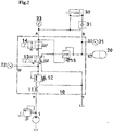
- FIG. 2 shows a hydraulic circuit diagram of the valve unit 10 according to the invention.
- the valve unit 10 includes a feed pressure input P, and the two valve unit outputs A, B, to which a likewise modified quick-change adapter can be connected.
- the valve unit 10 is designed exclusively for the control and pressure supply of the quick-change adapter, for safety reasons, no further consumers should be controlled or fed by the valve unit 10.
- a throttle 11 in combination with the pressure reducing valve 12 is provided on the input side.
- the system pressure P of the construction machine can be throttled and regulated to the system pressure M required within the valve unit 10 for the operation of the quick-change adapter.
- the pressure reducing valve 12 in particular allows a variable adjustment of the system pressure M.
- the valve unit outlet A serves to connect an unlocking pressure line of the quick-change adapter, while the valve unit outlet B is intended for the connection of the locking pressure line.
- A, B of the structurally simplified quick-change adapter is connected, which is constructed of a hydraulic cylinder 30 for actuating a locking means and the check valve 31.
- the unlocking pressure line A is connected to the rod side of the cylinder 30 while the lock pressure line B communicates with the bottom side.
- the check valve 31 ensures that no hydraulic medium can escape from the cylinder 30 on the rod side, as long as there is no corresponding control command for the valve opening on the check valve 31.
- the control of the check valve 31 takes place hydraulically by using a branch of the unlocking pressure line A as control pressure.
- the connection of the valve unit according to the invention can also be done in the reverse manner.
- the valve unit 10 is equipped with two-way valves 13, 14, which are electrically actuated via separate control channels.
- the first valve 13 is a 4/2-way valve and is on the input side to the output of the pressure reducing valve 12 in connection, i. the system pressure M is applied to the inlet of the valve 13.
- the two switching states a, b of the directional control valve 13 enable a connection of the system pressure M either with the valve inlet of the second directional valve 14 and thus indirectly with the unlocking pressure line A (switching state a) or alternatively with the valve unit output B for connection to the locking pressure line (switching state b).
- the second directional control valve which is designed as a 2/2-way valve, thus comprises two switching states a ', b', wherein in a switching state a ', the output of the directional control valve 13 is connected to the valve unit output A. In the second switching state b ', the valve 14 only blocks the volume flow from the valve 13 to the valve unit outlet A, but a return flow from the valve unit outlet A to the valve 13 is released.
- Both directional control valves 13, 14 comprise a pilot valve with electromagnetic actuation against spring preload, so that when the electromagnet is not actuated, both directional control valves 13, 14 are in the second switching position b, b 'as in FIG FIG. 2 remain displayed or switched to this state.
- the system pressure M is applied to the valve unit output B for the interlock pressure line to ensure a sufficient pressure level for maintaining the lock position of the hydraulic cylinder 30.
- the Entriegelungstiktechnisch A is connected via the directional control valve 14 to the directional control valve 13, wherein the directional control valve 13 ensures a return flow of Entriegelungstik effet A in the hydraulic tank T. For the locking operation of the quick-change adapter, it is thus sufficient to spend the directional control valve 13 in the second switching state b.
- the system pressure M is also applied to the directional control valve 14. If the directional control valve 14 is also in the first switching state a, the system pressure M is applied via both directional control valves 13, 14 to the valve unit output A for the unlocking pressure and the quick-change adapter is unlocked by pressurizing the annular chamber of the hydraulic cylinder 30.
- a pressure shut-off valve 15 is also integrated between the directional control valve 13 and the output of the locking pressure line B, that the connection between the directional control valve 13 and the output B interrupts, if the pressure level of the locking pressure line B exceeds a certain limit.
- the flow from the directional control valve 13 to the outlet B is to be opened by the pressure shut-off valve 15 when the pressure level at the first valve unit outlet A exceeds a limiting pressure. This is also necessary to prevent pressure build-up when unlocking is initiated.
- the pressure shut-off valve 15 acts redundantly to the check valve 31 of the quick-change adapter.
- valve unit 10 may include a pressure accumulator 20 to compensate for the failure of the hydraulic pump 1 caused by the drop in the system pressure M, so that the hydraulic cylinder 30 remains in the locked position.
- a pressure accumulator 20 to compensate for the failure of the hydraulic pump 1 caused by the drop in the system pressure M, so that the hydraulic cylinder 30 remains in the locked position.
- any pressure sensors 21, 22, 23 or measuring points may be integrated in the valve unit 10, for example in the area of the system pressure M and in the area of the unlocking pressure line A and the locking pressure line B.
- valve unit 10 is implemented in the superstructure of the construction machine, which offer more advantages in terms of locking security and universal functionality of the quick-change adapter.
- the control valves 13, 14 used in the proposed valve unit 10 are designed as a slide valve (valve 13) and a seat valve (valve 14). Due to the different construction type and the control of the two valves 13, 14 via separate channels results in a diversity in the valve assembly 10. A simultaneous failure or a simultaneous malfunction of both valves 13, 14 as a result of a common cause (design error, etc.) thereby excluded.
- valves 13, 14 are constructed so that when locking the quick coupler, the pressure medium is sufficiently controlled only by means of the valve 13.
- both valves 13, 14 in the necessary position i. the first shift position a, a 'are spent.
- the valve 13 remains in the second switching position b, whereby the pressurization on the locking side (bottom side) of the cylinder 30 is still maintained and therefore unlocking can not take place, even if the valve 14 in the switching position a '(unlock) should hang or is jammed in this circuit.
- the locking system of the quick change system is not only diverse but also redundant.
- the relevant locking redundancy results in this case both from the interconnection of the control valves 13, 14 and the positioning of the pressure relief valve 15, which acts redundantly to the check valve 31. Due to the fact that the system automatically switches to the safe state (locked) in the event of a fault, the system is additionally fail-safe. This is the case, for example, when a problem arises in the electrical system. In this case, the switching valves would 13 and 14 due to the bias in the de-energized states (second switching positions b, b ') connected, and automatically the safe state (locked) will be brought.
- valve assembly 10 allows a redundant, diverse as well as accident-safe interconnection of the quick-change adapter.
Landscapes
- Engineering & Computer Science (AREA)
- Mechanical Engineering (AREA)
- Mining & Mineral Resources (AREA)
- Civil Engineering (AREA)
- General Engineering & Computer Science (AREA)
- Structural Engineering (AREA)
- Fluid-Pressure Circuits (AREA)
- Operation Control Of Excavators (AREA)
Applications Claiming Priority (1)
| Application Number | Priority Date | Filing Date | Title |
|---|---|---|---|
| DE102015015809.0A DE102015015809A1 (de) | 2015-12-07 | 2015-12-07 | Ventileinheit für Schnellwechsler sowie Schnellwechselsystem |
Publications (3)
| Publication Number | Publication Date |
|---|---|
| EP3178997A2 true EP3178997A2 (fr) | 2017-06-14 |
| EP3178997A3 EP3178997A3 (fr) | 2017-09-06 |
| EP3178997B1 EP3178997B1 (fr) | 2019-08-21 |
Family
ID=57189787
Family Applications (1)
| Application Number | Title | Priority Date | Filing Date |
|---|---|---|---|
| EP16193639.8A Active EP3178997B1 (fr) | 2015-12-07 | 2016-10-13 | Ventileinheit für schnellwechsler sowie schnellwechselsystem |
Country Status (3)
| Country | Link |
|---|---|
| US (1) | US10214873B2 (fr) |
| EP (1) | EP3178997B1 (fr) |
| DE (1) | DE102015015809A1 (fr) |
Families Citing this family (9)
| Publication number | Priority date | Publication date | Assignee | Title |
|---|---|---|---|---|
| GB2569643B (en) * | 2017-12-22 | 2021-04-14 | Bamford Excavators Ltd | Locking system for a working machine |
| CN110094382B (zh) * | 2019-06-04 | 2024-08-13 | 徐州徐工挖掘机械有限公司 | 一种快换装置液压控制系统 |
| CN110905025B (zh) * | 2019-12-26 | 2024-08-06 | 三一重机有限公司 | 液压快换装置及挖掘机 |
| JP7402085B2 (ja) * | 2020-03-16 | 2023-12-20 | 株式会社小松製作所 | 作業機械の油圧システム、作業機械および油圧システムの制御方法 |
| CN112482474B (zh) * | 2020-11-12 | 2022-04-22 | 交通运输部广州打捞局 | 一种整平机控制装置和水下整平机 |
| WO2022107230A1 (fr) * | 2020-11-18 | 2022-05-27 | Smc株式会社 | Circuit de commande pneumatique équipé de caractéristique de sécurité |
| CN113847296A (zh) * | 2021-10-12 | 2021-12-28 | 中联重科土方机械有限公司 | 快换装置控制阀组、液压系统和挖掘机 |
| EP4335975B1 (fr) | 2022-09-06 | 2025-03-12 | Oilquick AB | Système de sécurité pour machine |
| CN115653951A (zh) * | 2022-10-20 | 2023-01-31 | 上海三一重机股份有限公司 | 作业机械、属具快换液压控制系统及控制方法 |
Family Cites Families (7)
| Publication number | Priority date | Publication date | Assignee | Title |
|---|---|---|---|---|
| DE19548943B4 (de) * | 1995-12-28 | 2005-05-04 | Bosch Rexroth Ag | Ventilanordnung |
| PT1318242E (pt) * | 2001-12-06 | 2007-01-31 | Geith Patents Ltd | Engate para acoplar um acessório a um braço de escavadora e sistema de comando deste engate |
| DE202008015191U1 (de) * | 2008-11-14 | 2009-02-26 | Gerhard Henle Besitzunternehmen E.K. | Schnellwechseleinrichtung |
| DE202012009838U1 (de) * | 2012-07-24 | 2013-10-25 | Kinshofer Gmbh | Schnellkuppler |
| US20150330053A1 (en) * | 2012-12-18 | 2015-11-19 | Jb Attachments Limited | A coupler |
| DE102014200469A1 (de) * | 2014-01-14 | 2015-07-16 | Robert Bosch Gmbh | Ventilvorrichtung und Verfahren zum Steuern eines Verbrauchers |
| JP6176666B2 (ja) * | 2014-04-08 | 2017-08-09 | キャタピラー エス エー アール エル | 作業機械におけるクイックカプラ用制御装置 |
-
2015
- 2015-12-07 DE DE102015015809.0A patent/DE102015015809A1/de not_active Withdrawn
-
2016
- 2016-10-13 EP EP16193639.8A patent/EP3178997B1/fr active Active
- 2016-12-07 US US15/371,287 patent/US10214873B2/en active Active
Non-Patent Citations (1)
| Title |
|---|
| None |
Also Published As
| Publication number | Publication date |
|---|---|
| EP3178997B1 (fr) | 2019-08-21 |
| US20170159263A1 (en) | 2017-06-08 |
| DE102015015809A1 (de) | 2017-06-08 |
| EP3178997A3 (fr) | 2017-09-06 |
| US10214873B2 (en) | 2019-02-26 |
Similar Documents
| Publication | Publication Date | Title |
|---|---|---|
| EP3178997B1 (fr) | Ventileinheit für schnellwechsler sowie schnellwechselsystem | |
| DE102004028437B3 (de) | Ventilanordnung | |
| DE102004052602B4 (de) | Ventilanordnung | |
| DE102018202148B3 (de) | Hydraulikventilverband mit Zwangsschaltung und Mobilhydrauliksystem | |
| DE112018002941T5 (de) | Lenkungssteuersystem und Verfahren zum Stoppen einer Lenkeinrichtung | |
| DE102016205125A1 (de) | Bremssystem, Schienenfahrzeug mit einem Bremssystem sowie Verfahren zum Betrieb eines Bremssystems | |
| EP2698477B1 (fr) | Attache rapide, procédé de fonctionnement d'une attache rapide et dispositif d'attache rapide | |
| EP1743979B1 (fr) | Agencement hydraulique | |
| DE102021117185A1 (de) | Vorsteuerneutralisierungssystem | |
| DE102021117193A1 (de) | Vorsteuerneutralisierungssystem | |
| DE202008015191U1 (de) | Schnellwechseleinrichtung | |
| EP2438310B1 (fr) | Ensemble soupape de sécurité pneumatique | |
| EP3443828A1 (fr) | Dispositif d'alimentation en fluide sous pression hydraulique et unité de soupape d'adaptateur | |
| DE102021117194A1 (de) | Vorsteuerneutralisierungssystem | |
| DE102014010174A1 (de) | Elektrohydraulisches Lenksystem | |
| EP2514977A2 (fr) | Bloc de presse | |
| DE102017106634B4 (de) | Flurförderzeug mit einer Klammereinrichtung zum Klammern einer Last | |
| DE102022113302B4 (de) | Hydrauliksystem zur Druckversorgung eines hydraulischen Aktuators | |
| EP2613059A2 (fr) | Dispositif de commande d'un actionneur actionné par un fluide pour un appareil de travail | |
| DE102017124948A1 (de) | Hydraulische Schaltungsanordnung | |
| EP0890030B1 (fr) | Circuit de securite | |
| EP2157319A1 (fr) | Commande hydraulique pour un moteur hydraulique | |
| DE102016212306A1 (de) | Zwischenblock und Kompaktachse mit einem Zwischenblock | |
| EP4229243B1 (fr) | Dispositif à changement rapide pourvu d'un dispositif de commande doté d'une soupape à commande mécanique et hydraulique | |
| EP3756435A1 (fr) | Dispositif de réglage d'un bras supérieur d'attelage hydraulique |
Legal Events
| Date | Code | Title | Description |
|---|---|---|---|
| PUAI | Public reference made under article 153(3) epc to a published international application that has entered the european phase |
Free format text: ORIGINAL CODE: 0009012 |
|
| STAA | Information on the status of an ep patent application or granted ep patent |
Free format text: STATUS: THE APPLICATION HAS BEEN PUBLISHED |
|
| AK | Designated contracting states |
Kind code of ref document: A2 Designated state(s): AL AT BE BG CH CY CZ DE DK EE ES FI FR GB GR HR HU IE IS IT LI LT LU LV MC MK MT NL NO PL PT RO RS SE SI SK SM TR |
|
| AX | Request for extension of the european patent |
Extension state: BA ME |
|
| PUAL | Search report despatched |
Free format text: ORIGINAL CODE: 0009013 |
|
| AK | Designated contracting states |
Kind code of ref document: A3 Designated state(s): AL AT BE BG CH CY CZ DE DK EE ES FI FR GB GR HR HU IE IS IT LI LT LU LV MC MK MT NL NO PL PT RO RS SE SI SK SM TR |
|
| AX | Request for extension of the european patent |
Extension state: BA ME |
|
| RIC1 | Information provided on ipc code assigned before grant |
Ipc: E02F 3/36 20060101AFI20170728BHEP Ipc: F15B 20/00 20060101ALI20170728BHEP Ipc: F15B 1/02 20060101ALI20170728BHEP Ipc: E02F 9/22 20060101ALN20170728BHEP |
|
| STAA | Information on the status of an ep patent application or granted ep patent |
Free format text: STATUS: REQUEST FOR EXAMINATION WAS MADE |
|
| 17P | Request for examination filed |
Effective date: 20180306 |
|
| STAA | Information on the status of an ep patent application or granted ep patent |
Free format text: STATUS: EXAMINATION IS IN PROGRESS |
|
| 17Q | First examination report despatched |
Effective date: 20180706 |
|
| GRAP | Despatch of communication of intention to grant a patent |
Free format text: ORIGINAL CODE: EPIDOSNIGR1 |
|
| STAA | Information on the status of an ep patent application or granted ep patent |
Free format text: STATUS: GRANT OF PATENT IS INTENDED |
|
| RIC1 | Information provided on ipc code assigned before grant |
Ipc: E02F 3/36 20060101AFI20190226BHEP Ipc: F15B 1/02 20060101ALI20190226BHEP Ipc: F15B 20/00 20060101ALI20190226BHEP Ipc: E02F 9/22 20060101ALN20190226BHEP |
|
| INTG | Intention to grant announced |
Effective date: 20190326 |
|
| GRAS | Grant fee paid |
Free format text: ORIGINAL CODE: EPIDOSNIGR3 |
|
| GRAA | (expected) grant |
Free format text: ORIGINAL CODE: 0009210 |
|
| STAA | Information on the status of an ep patent application or granted ep patent |
Free format text: STATUS: THE PATENT HAS BEEN GRANTED |
|
| AK | Designated contracting states |
Kind code of ref document: B1 Designated state(s): AL AT BE BG CH CY CZ DE DK EE ES FI FR GB GR HR HU IE IS IT LI LT LU LV MC MK MT NL NO PL PT RO RS SE SI SK SM TR |
|
| REG | Reference to a national code |
Ref country code: GB Ref legal event code: FG4D Free format text: NOT ENGLISH |
|
| REG | Reference to a national code |
Ref country code: CH Ref legal event code: EP |
|
| REG | Reference to a national code |
Ref country code: DE Ref legal event code: R096 Ref document number: 502016006172 Country of ref document: DE |
|
| REG | Reference to a national code |
Ref country code: AT Ref legal event code: REF Ref document number: 1169908 Country of ref document: AT Kind code of ref document: T Effective date: 20190915 |
|
| REG | Reference to a national code |
Ref country code: IE Ref legal event code: FG4D Free format text: LANGUAGE OF EP DOCUMENT: GERMAN |
|
| REG | Reference to a national code |
Ref country code: NL Ref legal event code: FP |
|
| REG | Reference to a national code |
Ref country code: SE Ref legal event code: TRGR |
|
| REG | Reference to a national code |
Ref country code: LT Ref legal event code: MG4D |
|
| PG25 | Lapsed in a contracting state [announced via postgrant information from national office to epo] |
Ref country code: PT Free format text: LAPSE BECAUSE OF FAILURE TO SUBMIT A TRANSLATION OF THE DESCRIPTION OR TO PAY THE FEE WITHIN THE PRESCRIBED TIME-LIMIT Effective date: 20191223 Ref country code: BG Free format text: LAPSE BECAUSE OF FAILURE TO SUBMIT A TRANSLATION OF THE DESCRIPTION OR TO PAY THE FEE WITHIN THE PRESCRIBED TIME-LIMIT Effective date: 20191121 Ref country code: LT Free format text: LAPSE BECAUSE OF FAILURE TO SUBMIT A TRANSLATION OF THE DESCRIPTION OR TO PAY THE FEE WITHIN THE PRESCRIBED TIME-LIMIT Effective date: 20190821 Ref country code: HR Free format text: LAPSE BECAUSE OF FAILURE TO SUBMIT A TRANSLATION OF THE DESCRIPTION OR TO PAY THE FEE WITHIN THE PRESCRIBED TIME-LIMIT Effective date: 20190821 Ref country code: NO Free format text: LAPSE BECAUSE OF FAILURE TO SUBMIT A TRANSLATION OF THE DESCRIPTION OR TO PAY THE FEE WITHIN THE PRESCRIBED TIME-LIMIT Effective date: 20191121 Ref country code: FI Free format text: LAPSE BECAUSE OF FAILURE TO SUBMIT A TRANSLATION OF THE DESCRIPTION OR TO PAY THE FEE WITHIN THE PRESCRIBED TIME-LIMIT Effective date: 20190821 |
|
| PG25 | Lapsed in a contracting state [announced via postgrant information from national office to epo] |
Ref country code: AL Free format text: LAPSE BECAUSE OF FAILURE TO SUBMIT A TRANSLATION OF THE DESCRIPTION OR TO PAY THE FEE WITHIN THE PRESCRIBED TIME-LIMIT Effective date: 20190821 Ref country code: ES Free format text: LAPSE BECAUSE OF FAILURE TO SUBMIT A TRANSLATION OF THE DESCRIPTION OR TO PAY THE FEE WITHIN THE PRESCRIBED TIME-LIMIT Effective date: 20190821 Ref country code: GR Free format text: LAPSE BECAUSE OF FAILURE TO SUBMIT A TRANSLATION OF THE DESCRIPTION OR TO PAY THE FEE WITHIN THE PRESCRIBED TIME-LIMIT Effective date: 20191122 Ref country code: IS Free format text: LAPSE BECAUSE OF FAILURE TO SUBMIT A TRANSLATION OF THE DESCRIPTION OR TO PAY THE FEE WITHIN THE PRESCRIBED TIME-LIMIT Effective date: 20191221 Ref country code: RS Free format text: LAPSE BECAUSE OF FAILURE TO SUBMIT A TRANSLATION OF THE DESCRIPTION OR TO PAY THE FEE WITHIN THE PRESCRIBED TIME-LIMIT Effective date: 20190821 Ref country code: LV Free format text: LAPSE BECAUSE OF FAILURE TO SUBMIT A TRANSLATION OF THE DESCRIPTION OR TO PAY THE FEE WITHIN THE PRESCRIBED TIME-LIMIT Effective date: 20190821 |
|
| PG25 | Lapsed in a contracting state [announced via postgrant information from national office to epo] |
Ref country code: TR Free format text: LAPSE BECAUSE OF FAILURE TO SUBMIT A TRANSLATION OF THE DESCRIPTION OR TO PAY THE FEE WITHIN THE PRESCRIBED TIME-LIMIT Effective date: 20190821 |
|
| PG25 | Lapsed in a contracting state [announced via postgrant information from national office to epo] |
Ref country code: RO Free format text: LAPSE BECAUSE OF FAILURE TO SUBMIT A TRANSLATION OF THE DESCRIPTION OR TO PAY THE FEE WITHIN THE PRESCRIBED TIME-LIMIT Effective date: 20190821 Ref country code: EE Free format text: LAPSE BECAUSE OF FAILURE TO SUBMIT A TRANSLATION OF THE DESCRIPTION OR TO PAY THE FEE WITHIN THE PRESCRIBED TIME-LIMIT Effective date: 20190821 Ref country code: DK Free format text: LAPSE BECAUSE OF FAILURE TO SUBMIT A TRANSLATION OF THE DESCRIPTION OR TO PAY THE FEE WITHIN THE PRESCRIBED TIME-LIMIT Effective date: 20190821 Ref country code: PL Free format text: LAPSE BECAUSE OF FAILURE TO SUBMIT A TRANSLATION OF THE DESCRIPTION OR TO PAY THE FEE WITHIN THE PRESCRIBED TIME-LIMIT Effective date: 20190821 |
|
| PG25 | Lapsed in a contracting state [announced via postgrant information from national office to epo] |
Ref country code: IS Free format text: LAPSE BECAUSE OF FAILURE TO SUBMIT A TRANSLATION OF THE DESCRIPTION OR TO PAY THE FEE WITHIN THE PRESCRIBED TIME-LIMIT Effective date: 20200224 Ref country code: MC Free format text: LAPSE BECAUSE OF FAILURE TO SUBMIT A TRANSLATION OF THE DESCRIPTION OR TO PAY THE FEE WITHIN THE PRESCRIBED TIME-LIMIT Effective date: 20190821 Ref country code: SK Free format text: LAPSE BECAUSE OF FAILURE TO SUBMIT A TRANSLATION OF THE DESCRIPTION OR TO PAY THE FEE WITHIN THE PRESCRIBED TIME-LIMIT Effective date: 20190821 Ref country code: SM Free format text: LAPSE BECAUSE OF FAILURE TO SUBMIT A TRANSLATION OF THE DESCRIPTION OR TO PAY THE FEE WITHIN THE PRESCRIBED TIME-LIMIT Effective date: 20190821 Ref country code: CZ Free format text: LAPSE BECAUSE OF FAILURE TO SUBMIT A TRANSLATION OF THE DESCRIPTION OR TO PAY THE FEE WITHIN THE PRESCRIBED TIME-LIMIT Effective date: 20190821 |
|
| REG | Reference to a national code |
Ref country code: CH Ref legal event code: PL |
|
| REG | Reference to a national code |
Ref country code: DE Ref legal event code: R097 Ref document number: 502016006172 Country of ref document: DE |
|
| PLBE | No opposition filed within time limit |
Free format text: ORIGINAL CODE: 0009261 |
|
| STAA | Information on the status of an ep patent application or granted ep patent |
Free format text: STATUS: NO OPPOSITION FILED WITHIN TIME LIMIT |
|
| PG2D | Information on lapse in contracting state deleted |
Ref country code: IS |
|
| PG25 | Lapsed in a contracting state [announced via postgrant information from national office to epo] |
Ref country code: LI Free format text: LAPSE BECAUSE OF NON-PAYMENT OF DUE FEES Effective date: 20191031 Ref country code: CH Free format text: LAPSE BECAUSE OF NON-PAYMENT OF DUE FEES Effective date: 20191031 Ref country code: LU Free format text: LAPSE BECAUSE OF NON-PAYMENT OF DUE FEES Effective date: 20191013 |
|
| 26N | No opposition filed |
Effective date: 20200603 |
|
| PG25 | Lapsed in a contracting state [announced via postgrant information from national office to epo] |
Ref country code: SI Free format text: LAPSE BECAUSE OF FAILURE TO SUBMIT A TRANSLATION OF THE DESCRIPTION OR TO PAY THE FEE WITHIN THE PRESCRIBED TIME-LIMIT Effective date: 20190821 |
|
| PG25 | Lapsed in a contracting state [announced via postgrant information from national office to epo] |
Ref country code: IE Free format text: LAPSE BECAUSE OF NON-PAYMENT OF DUE FEES Effective date: 20191013 |
|
| PG25 | Lapsed in a contracting state [announced via postgrant information from national office to epo] |
Ref country code: CY Free format text: LAPSE BECAUSE OF FAILURE TO SUBMIT A TRANSLATION OF THE DESCRIPTION OR TO PAY THE FEE WITHIN THE PRESCRIBED TIME-LIMIT Effective date: 20190821 |
|
| PG25 | Lapsed in a contracting state [announced via postgrant information from national office to epo] |
Ref country code: HU Free format text: LAPSE BECAUSE OF FAILURE TO SUBMIT A TRANSLATION OF THE DESCRIPTION OR TO PAY THE FEE WITHIN THE PRESCRIBED TIME-LIMIT; INVALID AB INITIO Effective date: 20161013 Ref country code: MT Free format text: LAPSE BECAUSE OF FAILURE TO SUBMIT A TRANSLATION OF THE DESCRIPTION OR TO PAY THE FEE WITHIN THE PRESCRIBED TIME-LIMIT Effective date: 20190821 |
|
| PG25 | Lapsed in a contracting state [announced via postgrant information from national office to epo] |
Ref country code: MK Free format text: LAPSE BECAUSE OF FAILURE TO SUBMIT A TRANSLATION OF THE DESCRIPTION OR TO PAY THE FEE WITHIN THE PRESCRIBED TIME-LIMIT Effective date: 20190821 |
|
| REG | Reference to a national code |
Ref country code: AT Ref legal event code: MM01 Ref document number: 1169908 Country of ref document: AT Kind code of ref document: T Effective date: 20211013 |
|
| PG25 | Lapsed in a contracting state [announced via postgrant information from national office to epo] |
Ref country code: AT Free format text: LAPSE BECAUSE OF NON-PAYMENT OF DUE FEES Effective date: 20211013 |
|
| P01 | Opt-out of the competence of the unified patent court (upc) registered |
Effective date: 20230607 |
|
| PGFP | Annual fee paid to national office [announced via postgrant information from national office to epo] |
Ref country code: NL Payment date: 20251024 Year of fee payment: 10 |
|
| PGFP | Annual fee paid to national office [announced via postgrant information from national office to epo] |
Ref country code: DE Payment date: 20251030 Year of fee payment: 10 |
|
| PGFP | Annual fee paid to national office [announced via postgrant information from national office to epo] |
Ref country code: GB Payment date: 20251024 Year of fee payment: 10 |
|
| PGFP | Annual fee paid to national office [announced via postgrant information from national office to epo] |
Ref country code: IT Payment date: 20251030 Year of fee payment: 10 |
|
| PGFP | Annual fee paid to national office [announced via postgrant information from national office to epo] |
Ref country code: FR Payment date: 20251024 Year of fee payment: 10 |
|
| PGFP | Annual fee paid to national office [announced via postgrant information from national office to epo] |
Ref country code: BE Payment date: 20251024 Year of fee payment: 10 |
|
| PGFP | Annual fee paid to national office [announced via postgrant information from national office to epo] |
Ref country code: SE Payment date: 20251024 Year of fee payment: 10 |