EP3179532B1 - Dichter querträger vom typ glas-metall, seine verwendung für elektrochemischen lithiumakkumulator und entsprechendes herstellungsverfahren - Google Patents
Dichter querträger vom typ glas-metall, seine verwendung für elektrochemischen lithiumakkumulator und entsprechendes herstellungsverfahren Download PDFInfo
- Publication number
- EP3179532B1 EP3179532B1 EP16202434.3A EP16202434A EP3179532B1 EP 3179532 B1 EP3179532 B1 EP 3179532B1 EP 16202434 A EP16202434 A EP 16202434A EP 3179532 B1 EP3179532 B1 EP 3179532B1
- Authority
- EP
- European Patent Office
- Prior art keywords
- glass
- pins
- orifice
- pin
- piston
- Prior art date
- Legal status (The legal status is an assumption and is not a legal conclusion. Google has not performed a legal analysis and makes no representation as to the accuracy of the status listed.)
- Active
Links
- 229910052751 metal Inorganic materials 0.000 title description 30
- 239000002184 metal Substances 0.000 title description 30
- WHXSMMKQMYFTQS-UHFFFAOYSA-N Lithium Chemical compound [Li] WHXSMMKQMYFTQS-UHFFFAOYSA-N 0.000 title description 8
- 229910052744 lithium Inorganic materials 0.000 title description 8
- 238000004519 manufacturing process Methods 0.000 title description 3
- 239000011521 glass Substances 0.000 claims description 34
- 238000000034 method Methods 0.000 claims description 31
- XAGFODPZIPBFFR-UHFFFAOYSA-N aluminium Chemical compound [Al] XAGFODPZIPBFFR-UHFFFAOYSA-N 0.000 claims description 26
- 238000005245 sintering Methods 0.000 claims description 26
- 229910052782 aluminium Inorganic materials 0.000 claims description 24
- 230000008569 process Effects 0.000 claims description 16
- OKTJSMMVPCPJKN-UHFFFAOYSA-N Carbon Chemical compound [C] OKTJSMMVPCPJKN-UHFFFAOYSA-N 0.000 claims description 14
- 229910052799 carbon Inorganic materials 0.000 claims description 8
- 239000012777 electrically insulating material Substances 0.000 claims description 8
- 229910002804 graphite Inorganic materials 0.000 claims description 6
- 239000010439 graphite Substances 0.000 claims description 6
- 239000004411 aluminium Substances 0.000 claims description 4
- 238000003780 insertion Methods 0.000 claims description 4
- 230000037431 insertion Effects 0.000 claims description 4
- 238000006073 displacement reaction Methods 0.000 claims description 3
- 238000011049 filling Methods 0.000 claims description 2
- 229910001416 lithium ion Inorganic materials 0.000 description 39
- HBBGRARXTFLTSG-UHFFFAOYSA-N Lithium ion Chemical compound [Li+] HBBGRARXTFLTSG-UHFFFAOYSA-N 0.000 description 15
- 241000920340 Pion Species 0.000 description 13
- 239000000463 material Substances 0.000 description 13
- 238000003466 welding Methods 0.000 description 11
- 238000007789 sealing Methods 0.000 description 9
- 230000006870 function Effects 0.000 description 7
- RYGMFSIKBFXOCR-UHFFFAOYSA-N Copper Chemical compound [Cu] RYGMFSIKBFXOCR-UHFFFAOYSA-N 0.000 description 6
- 241001639412 Verres Species 0.000 description 6
- 229910052802 copper Inorganic materials 0.000 description 6
- 239000010949 copper Substances 0.000 description 6
- 238000010292 electrical insulation Methods 0.000 description 6
- 238000010438 heat treatment Methods 0.000 description 6
- 229920000642 polymer Polymers 0.000 description 6
- 238000002490 spark plasma sintering Methods 0.000 description 6
- RTAQQCXQSZGOHL-UHFFFAOYSA-N Titanium Chemical compound [Ti] RTAQQCXQSZGOHL-UHFFFAOYSA-N 0.000 description 5
- 239000000470 constituent Substances 0.000 description 5
- 238000000280 densification Methods 0.000 description 5
- 238000004806 packaging method and process Methods 0.000 description 5
- 239000000843 powder Substances 0.000 description 5
- PXHVJJICTQNCMI-UHFFFAOYSA-N Nickel Chemical compound [Ni] PXHVJJICTQNCMI-UHFFFAOYSA-N 0.000 description 4
- XUIMIQQOPSSXEZ-UHFFFAOYSA-N Silicon Chemical compound [Si] XUIMIQQOPSSXEZ-UHFFFAOYSA-N 0.000 description 4
- 230000008901 benefit Effects 0.000 description 4
- 238000002788 crimping Methods 0.000 description 4
- 239000003792 electrolyte Substances 0.000 description 4
- 239000011810 insulating material Substances 0.000 description 4
- 238000002844 melting Methods 0.000 description 4
- 230000008018 melting Effects 0.000 description 4
- 241001080024 Telles Species 0.000 description 3
- 239000002131 composite material Substances 0.000 description 3
- 238000002955 isolation Methods 0.000 description 3
- 230000035515 penetration Effects 0.000 description 3
- 239000002861 polymer material Substances 0.000 description 3
- 229910052710 silicon Inorganic materials 0.000 description 3
- 239000010703 silicon Substances 0.000 description 3
- 239000000758 substrate Substances 0.000 description 3
- XLYOFNOQVPJJNP-UHFFFAOYSA-N water Substances O XLYOFNOQVPJJNP-UHFFFAOYSA-N 0.000 description 3
- 208000031968 Cadaver Diseases 0.000 description 2
- DGAQECJNVWCQMB-PUAWFVPOSA-M Ilexoside XXIX Chemical compound C[C@@H]1CC[C@@]2(CC[C@@]3(C(=CC[C@H]4[C@]3(CC[C@@H]5[C@@]4(CC[C@@H](C5(C)C)OS(=O)(=O)[O-])C)C)[C@@H]2[C@]1(C)O)C)C(=O)O[C@H]6[C@@H]([C@H]([C@@H]([C@H](O6)CO)O)O)O.[Na+] DGAQECJNVWCQMB-PUAWFVPOSA-M 0.000 description 2
- 229910012851 LiCoO 2 Inorganic materials 0.000 description 2
- 229910010707 LiFePO 4 Inorganic materials 0.000 description 2
- 229910002992 LiNi0.33Mn0.33Co0.33O2 Inorganic materials 0.000 description 2
- OAICVXFJPJFONN-UHFFFAOYSA-N Phosphorus Chemical compound [P] OAICVXFJPJFONN-UHFFFAOYSA-N 0.000 description 2
- ZLMJMSJWJFRBEC-UHFFFAOYSA-N Potassium Chemical compound [K] ZLMJMSJWJFRBEC-UHFFFAOYSA-N 0.000 description 2
- 239000000919 ceramic Substances 0.000 description 2
- 238000010894 electron beam technology Methods 0.000 description 2
- 239000007788 liquid Substances 0.000 description 2
- 229910052759 nickel Inorganic materials 0.000 description 2
- 230000002093 peripheral effect Effects 0.000 description 2
- 229910052700 potassium Inorganic materials 0.000 description 2
- 239000011591 potassium Substances 0.000 description 2
- 230000033458 reproduction Effects 0.000 description 2
- 229910052708 sodium Inorganic materials 0.000 description 2
- 239000011734 sodium Substances 0.000 description 2
- 229910001220 stainless steel Inorganic materials 0.000 description 2
- 239000010935 stainless steel Substances 0.000 description 2
- 238000003860 storage Methods 0.000 description 2
- 239000010936 titanium Substances 0.000 description 2
- 229910052719 titanium Inorganic materials 0.000 description 2
- 239000010963 304 stainless steel Substances 0.000 description 1
- CIWBSHSKHKDKBQ-JLAZNSOCSA-N Ascorbic acid Chemical compound OC[C@H](O)[C@H]1OC(=O)C(O)=C1O CIWBSHSKHKDKBQ-JLAZNSOCSA-N 0.000 description 1
- 229910001290 LiPF6 Inorganic materials 0.000 description 1
- 239000004743 Polypropylene Substances 0.000 description 1
- 229910000589 SAE 304 stainless steel Inorganic materials 0.000 description 1
- 229910000831 Steel Inorganic materials 0.000 description 1
- QVGXLLKOCUKJST-UHFFFAOYSA-N atomic oxygen Chemical compound [O] QVGXLLKOCUKJST-UHFFFAOYSA-N 0.000 description 1
- 150000004649 carbonic acid derivatives Chemical class 0.000 description 1
- 229910052729 chemical element Inorganic materials 0.000 description 1
- 238000006243 chemical reaction Methods 0.000 description 1
- 239000011248 coating agent Substances 0.000 description 1
- 238000000576 coating method Methods 0.000 description 1
- 239000004020 conductor Substances 0.000 description 1
- 238000009770 conventional sintering Methods 0.000 description 1
- 238000001816 cooling Methods 0.000 description 1
- 238000000354 decomposition reaction Methods 0.000 description 1
- 230000001627 detrimental effect Effects 0.000 description 1
- 230000000694 effects Effects 0.000 description 1
- 238000003487 electrochemical reaction Methods 0.000 description 1
- 239000007772 electrode material Substances 0.000 description 1
- 239000002657 fibrous material Substances 0.000 description 1
- 238000009459 flexible packaging Methods 0.000 description 1
- 239000011888 foil Substances 0.000 description 1
- 239000000499 gel Substances 0.000 description 1
- 239000002241 glass-ceramic Substances 0.000 description 1
- 230000017525 heat dissipation Effects 0.000 description 1
- 238000000265 homogenisation Methods 0.000 description 1
- 238000007731 hot pressing Methods 0.000 description 1
- 238000009434 installation Methods 0.000 description 1
- 238000009413 insulation Methods 0.000 description 1
- 239000002608 ionic liquid Substances 0.000 description 1
- 229940006487 lithium cation Drugs 0.000 description 1
- 229910003002 lithium salt Inorganic materials 0.000 description 1
- 159000000002 lithium salts Chemical class 0.000 description 1
- 239000007769 metal material Substances 0.000 description 1
- 150000002739 metals Chemical class 0.000 description 1
- 239000000203 mixture Substances 0.000 description 1
- 239000011185 multilayer composite material Substances 0.000 description 1
- 239000007773 negative electrode material Substances 0.000 description 1
- 239000005486 organic electrolyte Substances 0.000 description 1
- 239000003960 organic solvent Substances 0.000 description 1
- 229910052760 oxygen Inorganic materials 0.000 description 1
- 239000001301 oxygen Substances 0.000 description 1
- 239000002245 particle Substances 0.000 description 1
- 229910052698 phosphorus Inorganic materials 0.000 description 1
- 239000011574 phosphorus Substances 0.000 description 1
- 239000004033 plastic Substances 0.000 description 1
- 229920006254 polymer film Polymers 0.000 description 1
- -1 polypropylene Polymers 0.000 description 1
- 229920001155 polypropylene Polymers 0.000 description 1
- 230000008092 positive effect Effects 0.000 description 1
- 238000007493 shaping process Methods 0.000 description 1
- 239000007787 solid Substances 0.000 description 1
- 239000010959 steel Substances 0.000 description 1
- 230000007704 transition Effects 0.000 description 1
- 238000002604 ultrasonography Methods 0.000 description 1
Images


Classifications
-
- C—CHEMISTRY; METALLURGY
- C03—GLASS; MINERAL OR SLAG WOOL
- C03C—CHEMICAL COMPOSITION OF GLASSES, GLAZES OR VITREOUS ENAMELS; SURFACE TREATMENT OF GLASS; SURFACE TREATMENT OF FIBRES OR FILAMENTS MADE FROM GLASS, MINERALS OR SLAGS; JOINING GLASS TO GLASS OR OTHER MATERIALS
- C03C3/00—Glass compositions
- C03C3/04—Glass compositions containing silica
- C03C3/076—Glass compositions containing silica with 40% to 90% silica, by weight
- C03C3/097—Glass compositions containing silica with 40% to 90% silica, by weight containing phosphorus, niobium or tantalum
-
- C—CHEMISTRY; METALLURGY
- C03—GLASS; MINERAL OR SLAG WOOL
- C03C—CHEMICAL COMPOSITION OF GLASSES, GLAZES OR VITREOUS ENAMELS; SURFACE TREATMENT OF GLASS; SURFACE TREATMENT OF FIBRES OR FILAMENTS MADE FROM GLASS, MINERALS OR SLAGS; JOINING GLASS TO GLASS OR OTHER MATERIALS
- C03C8/00—Enamels; Glazes; Fusion seal compositions being frit compositions having non-frit additions
- C03C8/02—Frit compositions, i.e. in a powdered or comminuted form
- C03C8/08—Frit compositions, i.e. in a powdered or comminuted form containing phosphorus
-
- C—CHEMISTRY; METALLURGY
- C03—GLASS; MINERAL OR SLAG WOOL
- C03C—CHEMICAL COMPOSITION OF GLASSES, GLAZES OR VITREOUS ENAMELS; SURFACE TREATMENT OF GLASS; SURFACE TREATMENT OF FIBRES OR FILAMENTS MADE FROM GLASS, MINERALS OR SLAGS; JOINING GLASS TO GLASS OR OTHER MATERIALS
- C03C8/00—Enamels; Glazes; Fusion seal compositions being frit compositions having non-frit additions
- C03C8/24—Fusion seal compositions being frit compositions having non-frit additions, i.e. for use as seals between dissimilar materials, e.g. glass and metal; Glass solders
-
- H—ELECTRICITY
- H01—ELECTRIC ELEMENTS
- H01M—PROCESSES OR MEANS, e.g. BATTERIES, FOR THE DIRECT CONVERSION OF CHEMICAL ENERGY INTO ELECTRICAL ENERGY
- H01M10/00—Secondary cells; Manufacture thereof
- H01M10/05—Accumulators with non-aqueous electrolyte
- H01M10/052—Li-accumulators
- H01M10/0525—Rocking-chair batteries, i.e. batteries with lithium insertion or intercalation in both electrodes; Lithium-ion batteries
-
- H—ELECTRICITY
- H01—ELECTRIC ELEMENTS
- H01M—PROCESSES OR MEANS, e.g. BATTERIES, FOR THE DIRECT CONVERSION OF CHEMICAL ENERGY INTO ELECTRICAL ENERGY
- H01M50/00—Constructional details or processes of manufacture of the non-active parts of electrochemical cells other than fuel cells, e.g. hybrid cells
- H01M50/10—Primary casings; Jackets or wrappings
- H01M50/147—Lids or covers
- H01M50/155—Lids or covers characterised by the material
- H01M50/157—Inorganic material
- H01M50/159—Metals
-
- H—ELECTRICITY
- H01—ELECTRIC ELEMENTS
- H01M—PROCESSES OR MEANS, e.g. BATTERIES, FOR THE DIRECT CONVERSION OF CHEMICAL ENERGY INTO ELECTRICAL ENERGY
- H01M50/00—Constructional details or processes of manufacture of the non-active parts of electrochemical cells other than fuel cells, e.g. hybrid cells
- H01M50/10—Primary casings; Jackets or wrappings
- H01M50/183—Sealing members
- H01M50/186—Sealing members characterised by the disposition of the sealing members
-
- H—ELECTRICITY
- H01—ELECTRIC ELEMENTS
- H01M—PROCESSES OR MEANS, e.g. BATTERIES, FOR THE DIRECT CONVERSION OF CHEMICAL ENERGY INTO ELECTRICAL ENERGY
- H01M50/00—Constructional details or processes of manufacture of the non-active parts of electrochemical cells other than fuel cells, e.g. hybrid cells
- H01M50/10—Primary casings; Jackets or wrappings
- H01M50/183—Sealing members
- H01M50/19—Sealing members characterised by the material
- H01M50/191—Inorganic material
-
- H—ELECTRICITY
- H01—ELECTRIC ELEMENTS
- H01M—PROCESSES OR MEANS, e.g. BATTERIES, FOR THE DIRECT CONVERSION OF CHEMICAL ENERGY INTO ELECTRICAL ENERGY
- H01M50/00—Constructional details or processes of manufacture of the non-active parts of electrochemical cells other than fuel cells, e.g. hybrid cells
- H01M50/50—Current conducting connections for cells or batteries
- H01M50/543—Terminals
- H01M50/552—Terminals characterised by their shape
- H01M50/553—Terminals adapted for prismatic, pouch or rectangular cells
-
- H—ELECTRICITY
- H01—ELECTRIC ELEMENTS
- H01M—PROCESSES OR MEANS, e.g. BATTERIES, FOR THE DIRECT CONVERSION OF CHEMICAL ENERGY INTO ELECTRICAL ENERGY
- H01M50/00—Constructional details or processes of manufacture of the non-active parts of electrochemical cells other than fuel cells, e.g. hybrid cells
- H01M50/50—Current conducting connections for cells or batteries
- H01M50/543—Terminals
- H01M50/552—Terminals characterised by their shape
- H01M50/559—Terminals adapted for cells having curved cross-section, e.g. round, elliptic or button cells
-
- C—CHEMISTRY; METALLURGY
- C03—GLASS; MINERAL OR SLAG WOOL
- C03C—CHEMICAL COMPOSITION OF GLASSES, GLAZES OR VITREOUS ENAMELS; SURFACE TREATMENT OF GLASS; SURFACE TREATMENT OF FIBRES OR FILAMENTS MADE FROM GLASS, MINERALS OR SLAGS; JOINING GLASS TO GLASS OR OTHER MATERIALS
- C03C27/00—Joining pieces of glass to pieces of other inorganic material; Joining glass to glass other than by fusing
- C03C27/02—Joining pieces of glass to pieces of other inorganic material; Joining glass to glass other than by fusing by fusing glass directly to metal
-
- C—CHEMISTRY; METALLURGY
- C03—GLASS; MINERAL OR SLAG WOOL
- C03C—CHEMICAL COMPOSITION OF GLASSES, GLAZES OR VITREOUS ENAMELS; SURFACE TREATMENT OF GLASS; SURFACE TREATMENT OF FIBRES OR FILAMENTS MADE FROM GLASS, MINERALS OR SLAGS; JOINING GLASS TO GLASS OR OTHER MATERIALS
- C03C29/00—Joining metals with the aid of glass
-
- H—ELECTRICITY
- H01—ELECTRIC ELEMENTS
- H01M—PROCESSES OR MEANS, e.g. BATTERIES, FOR THE DIRECT CONVERSION OF CHEMICAL ENERGY INTO ELECTRICAL ENERGY
- H01M4/00—Electrodes
- H01M4/02—Electrodes composed of, or comprising, active material
- H01M4/36—Selection of substances as active materials, active masses, active liquids
- H01M4/48—Selection of substances as active materials, active masses, active liquids of inorganic oxides or hydroxides
- H01M4/485—Selection of substances as active materials, active masses, active liquids of inorganic oxides or hydroxides of mixed oxides or hydroxides for inserting or intercalating light metals, e.g. LiTi2O4 or LiTi2OxFy
-
- Y—GENERAL TAGGING OF NEW TECHNOLOGICAL DEVELOPMENTS; GENERAL TAGGING OF CROSS-SECTIONAL TECHNOLOGIES SPANNING OVER SEVERAL SECTIONS OF THE IPC; TECHNICAL SUBJECTS COVERED BY FORMER USPC CROSS-REFERENCE ART COLLECTIONS [XRACs] AND DIGESTS
- Y02—TECHNOLOGIES OR APPLICATIONS FOR MITIGATION OR ADAPTATION AGAINST CLIMATE CHANGE
- Y02E—REDUCTION OF GREENHOUSE GAS [GHG] EMISSIONS, RELATED TO ENERGY GENERATION, TRANSMISSION OR DISTRIBUTION
- Y02E60/00—Enabling technologies; Technologies with a potential or indirect contribution to GHG emissions mitigation
- Y02E60/10—Energy storage using batteries
Definitions
- the present invention relates to a water-metal type leaktight crossing.
- the invention relates to a glass-to-metal feed which forms a terminal for a lithium electrochemical accumulator, such as a lithium-ion battery.
- the invention aims firstly at improving the electrical insulation and watertightness characteristics while ensuring good electrical conduction on both sides of the crossing.
- crossing it is specified that we hear the usual technological sense, that is to say a device for passing an electrical conductive element through a wall and isolating the conductor of this wall.
- the invention can be implemented in any application that requires a sealed crossing.
- a lithium-ion battery or accumulator usually comprises at least one electrochemical cell C consisting of an electrolyte constituent 1 between a positive electrode or cathode 2 and a negative electrode or anode 3, a current collector 4 connected to the cathode 2 , a current collector 5 connected to the anode 3 and finally a package 6 arranged to contain the electrochemical cell with sealing while being traversed by a portion of the current collectors 4, 5.
- the electrolyte component 1 may be of solid, liquid or gel form.
- the constituent may comprise a polymer separator, ceramic or microporous composite soaked with organic electrolyte (s) or ionic liquid type that allows the displacement of the lithium ion from the cathode to the cathode. anode for a charge and vice versa for a discharge, which generates the current.
- the electrolyte is generally a mixture of organic solvents, for example carbonates in which is added a lithium salt typically LiPF6.
- the positive electrode or cathode 2 consists of Lithium cation insertion materials which are generally composite, such as LiFePO 4 , LiCoO 2 , LiNi 0.33 Mn 0.33 Co 0.33 O 2 .
- the negative electrode or anode 3 is very often made of graphite carbon or Li 4 TiO 5 O 12 (titanate material), possibly also based on silicon or silicon-based composite.
- the current collector 4 connected to the positive electrode is generally made of aluminum.
- the current collector 5 connected to the negative electrode is generally copper, nickel-plated copper or aluminum.
- a lithium-ion battery or accumulator may of course include a plurality of electrochemical cells which are stacked on each other.
- a Li-ion battery or accumulator uses a couple of materials at the anode and the cathode allowing it to operate at a high voltage level, typically equal to 3.6 volts.
- the package is then either flexible or rigid and is in this case a kind of case.
- the flexible packages are usually made from a multilayer composite material consisting of a stack of aluminum layers covered by one or more adhesive-laminated polymer film (s).
- Rigid packaging is used when the targeted applications are binding where a long life is sought, with for example much higher pressures to be withstood and a stricter required sealing level, typically less than 10 -8. mbar.l / s, or in high-stress environments such as aeronautics or space.
- a rigid packaging used consists of a metal case, usually a lightweight and inexpensive metal, typically stainless steel (316L stainless steel or 304 stainless steel) or aluminum (Al 1050 or Al 3003), or in titanium.
- stainless steel typically stainless steel (316L stainless steel or 304 stainless steel) or aluminum (Al 1050 or Al 3003), or in titanium.
- aluminum is generally preferred for its high thermal conductivity coefficient as explained hereinafter. Cases made of steel coated with a bimetal copper / nickel coating have already been envisaged in the patent application. WO 2010/113502 .
- Plastic boxes in particular entirely made of polymer, have also already been envisaged, in particular in the patent application. US 2010316094 . Although having a significant mechanical strength, these boxes are unlikely to be economically viable because of the price of their constituent material.
- FIG. figure 3 One of the types of cylindrical rigid case, usually manufactured for a high capacity Li-ion accumulator with a lifetime greater than 10 years, is illustrated in FIG. figure 3 .
- the housing 6 has a cylindrical lateral envelope 7, a bottom 8 at one end, a cover 9 at the other end, the bottom 8 and the cover 9 being assembled to the envelope 7.
- the cover 9 supports the poles or output terminals of the current 40, 50.
- One of the output terminals (poles), for example the positive terminal 40 is soldered to the cover 9 while the other output terminal , for example the negative terminal 50, passes through the cover 9 with interposition of a not shown seal which electrically isolates the negative terminal 50 of the cover.
- the electrochemical cell or cells is (are) de facto contained in a chamber completely sealed vis-à-vis the outside.
- the first type also consists of a rigid housing consisting of a stamped cup and a cover welded together on their periphery by laser.
- the current collectors comprise a bushing with a portion projecting from the top of the case and which forms a terminal also known as the apparent pole of the battery.
- FIG. figure 4 A first example of assembly of such a bushing 1 forming a terminal with the current collector 2 and with the cover 3 of a housing is shown in FIG. figure 4 : the collector 2, typically copper in the form of a male part internally threaded is fixed by screwing with a nut 2 type M5 or M8.
- the two insulating washers 5A, 5B are identical and each comprise a bearing portion 50A, 50B and a guiding and centering portion 51A, 51B.
- the bearing portion 50A is in surface abutment with pressure against both the face 30 of the wall of the lid 3 and against the bearing washer 6 of the nut 4.
- the bearing portion 50B is in surface support both against the opposite face 31 of the cover 3 and against the bearing portion 20 of the current collector 2.
- the guide and centering portions 51A, 51B are, for their part, both in surface bearing with pressure against the edge of the through hole 32 of the cover 2 and against the collector 2.
- FIG. figure 5 A second example of assembly of a bushing 1 forming a terminal with the current collector 2 and with the cover 3 of a housing is shown in FIG. figure 5 the collector 2, typically made of copper, in the form of a male part internally threaded is fixed by crimping the collector on the bearing washer 6.
- the collector 2 typically made of copper
- the two washers 5A, 5B of electrical insulating material with their bearing portions 50A, 50B and their guide and centering portions 51A, 51B which are arranged identically and perform the same functions as in the first example.
- the fixing by crimping according to this second example is done without the use of additional parts, such as the nut 4 of the first example.
- the crimping is achieved by mechanical crushing of a crimping portion 21 disposed on the outside of the cylindrical portion of the collector 2, against the bearing washer 6.
- the second type consists of a rigid housing consisting of a machined bottom and a cover welded together on their periphery by laser.
- the current collectors consist in part of metal wires or pins.
- the pion (s) is (are) welded (s) by electrical welding or by ultrasound to the part of the corresponding current collector connected itself to one of the electrodes of an electrochemical cell or a stack of electrochemical cells.
- a glass ball send the pin thus forming what is commonly called a glass-to-metal crossing (TVM).
- TVM glass-to-metal crossing
- a ring around the glass ball and usually in the same metal as the case is welded to the latter.
- FIG. 6 a TVM of Li-ion battery as described in the patent US7687200B2 : the lid 3 of the battery box is pierced with a not shown orifice closed by a glass gasket 5 which glass a metal pin 2 completely through the cover 3 and thus the housing.
- This crossing TVM makes it possible to ensure the isolation of the two terminals of the battery, one in general of positive polarity being ensured by the metal case and the other generally negative by the metal pin 2 isolated from the cover 3 and thus the housing.
- Glass has the advantage of having better water permeation characteristics than polymeric materials and good thermal compatibility with metals which can constitute a battery pack, in particular aluminum.
- the TVM bushings are therefore compared to the bushings of the first type mentioned above with polymer washers of the bushings which make it possible to guarantee better electrical insulation and better sealing while ensuring good electrical conduction from one side to the other of the battery box. .
- the document CN 105 121 639 A discloses a sealed passage for a Li-ion battery comprising a metal pin sent in a glass or glass-ceramic joint, the glass can be a frit.
- the object of the invention is to meet part of this need.
- step a / and / or step d / the placing of a sheet of carbon paper respectively between the base of the tool and the body and / or between the body and the piston of the tooling.
- Each sheet of carbon paper avoids unwanted welds between the different components during the application of the flash sintering cycle.
- the current passages necessary for carrying out the flash process pass through each sheet of carbon paper, in order to separate the glass part from the metal pins, after densification of the glass frit.
- step a / and / or step d / the placing of a metal sheet, preferably aluminum, is made in contact with the lower end of the pion (s) and / or with the upper end of the or pawns.
- the attachment of the insulating glass frit is performed on each metal sheet.
- each sheet makes it possible to close the battery box by a suitable welding means, such as TIG welding, laser, electron beam welding.
- a suitable welding means such as TIG welding, laser, electron beam welding.
- the electrically insulating material is a sintered glass.
- all the electrically insulative materials that can be sintered by a flash sintering technique may be suitable for carrying out a crossing according to the invention. It is sufficient for the insulating material to have a melting point that is relatively close to the flash sintering temperature and that the latter is compatible with the various other materials, in particular those of the pins and the metal wall.
- the inventors started from an aluminum battery case cover, and therefore, all insulating materials capable of forming at a temperature below the melting temperature of aluminum are suitable to the application.
- the glass frit is perfectly suitable.
- the invention consists in applying a flash sintering process to a frit of electrically insulating material, preferably a glass frit, so that it constitutes the electrical insulation and sealing seal of a bushing.
- the sintered glass according to this process has a very good thermal compatibility with aluminum which is the constituent material of the lithium battery packs.
- the crossing obtained according to the invention constitutes a sealed passage, which allows through the (x) metal pion (s) an electrical conduction from one side to the other of the passage, and which has thanks to the sintered glass seal electrical insulation and sealing.
- flash sintering process is meant the usual technological sense, as detailed in the publication [2].
- SPS Spark Plasma Sintering
- PECS Pulsed Electric Current Sintering
- Flash sintering is a sintering process derived from traditional hot pressing. Therefore, the flash sintering installations also include a water-cooled enclosure, a hydraulic press system, and a control-command that controls the temperature, the compressive force, and the vacuum or gaseous atmosphere. inside the enclosure.
- flash sintering method Another advantage of the flash sintering method is that the thermal power that is supplied is not only homogeneously distributed on the macroscopic scale on the volume of powder to be pressed, but also transmitted, on a microscopic scale, exactly at the points for which energy is necessary for the sintering process, namely the points of contact between the powder particles. As a result, flash sintering is of better quality with low grain growth.
- a sintered glass-based gasket made by an SPS process not only ensures the various desired functions (current flow, sealing) but also makes it possible to dispense with passing the glass frit into the liquid state. , to obtain complex geometries directly to the ribs. In addition, this also makes it possible to increase the complexity of the passages by being able to make outputs of several terminals.
- a metal foil is welded to at least one end of a pin, the soldered sheet forming part of a current collector.
- the sintered glass is based on alkaline oxides.
- the pion (s) can (or preferably) be made of aluminum.
- each pin forms a terminal for lithium electrochemical accumulator, of Li-ion type.
- a lithium-ion (Li-ion) battery or accumulator having a housing with a cover through which a previously described feedthrough can be made.
- the cover may be aluminum, such as aluminum 1050 or 3003 and the one or pions is (are) aluminum or nickel or copper.
- the negative electrode material (s) may be chosen from the group comprising graphite, lithium, titanate oxide Li 4 TiO 5 O 12 ; and the electrode material (s) positive (s) can be selected from the group comprising LiFePO 4 , LiCoO 2 , LiNi 0.33 Mn 0.33 Co 0.33 O 2 .
- the Figures 1 to 6 relate to different examples of Li-ion accumulator, boxes and bushings forming Li-ion storage terminals according to the state of the art. These Figures 1 to 6 have already been commented on in the preamble and are therefore not more so below.
- the bushing 1 according to the invention is made through a non-opening opening on either side of a lid 3 of a Li-ion battery box.
- the bushing 1 shown comprises two pins 2, preferably aluminum, passing through the orifice 32 fixed inside thereof by means of an insulating glass frit seal 5, obtained by the application of a method flash sintering.
- a metal sheet 7 which allows the closing of the battery case by a suitable welding means, such as TIG welding, laser welding electron beam. More specifically, the lower metal sheet 7, that is to say that intended to come inside the battery box is intended to be welded to the current collector of one or the other of the electrodes of the electrochemical cell constituting the accumulator.
- a tool 9 graphite as shown schematically in figure 8 .
- This tool 9 is adapted to implement a flash sintering method.
- the tooling 9 comprises an upper part forming a press piston 90, a lower part forming a base 91, the piston 90 being able to move relatively between outer peripheral walls 92, 93.
- the peripheral walls 92 allow to define a space inside which the glass frit is confined, while the outermost outer walls 93 determine the positioning space of the lid 3.
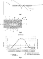
- the inventors have carried out different tests of an alternating stack of 5 'glass frit and aluminum pegs 2 as shown in FIG. figure 10 , by means of tooling 9 and according to different flash sintering cycles.
- the Figures 11A and 11B show in section the densification of the substrate obtained at a temperature of 450 ° C, respectively at the same magnification of 350 times but with a different contrast adjustment.
- the Figures 12A and 12B show in section the densification of the substrate obtained at a temperature of 480 ° C., respectively at a magnification of 350 times and 2000 times.
- the Figures 13A and 13B show in section the densification of the substrate obtained at a temperature of 500 ° C., respectively at a magnification of 350 times and 2000 times.
- the crossing 1 according to the invention can be carried out on a lid 3 of Li-ion battery case both in a cylindrical geometry as a prismatic geometry.
- the terminal 1 according to the invention is for example negative
- the positive terminal can be made, for example directly by welding, also on the cover 3.
- the material of the seal is a glass frit
- any insulating electrical material may be suitable provided that it is relatively close to the melting point, and that the temperature of the flash sintering process is compatible with the different other materials, aluminum pions and cover in particular.
- the temperature of the flash sintering process should be slightly lower than the melting temperature.
- the crossing comprises two pins 2 which each constitute a terminal of the accumulator. It is entirely possible to make a sealed passage with only one terminal and to use the battery box as the second terminal. More generally, it is possible to envisage sealed penetrations according to the invention integrating a number equal to one, two, three, four ... conductive pins.
Landscapes
- Chemical & Material Sciences (AREA)
- Chemical Kinetics & Catalysis (AREA)
- General Chemical & Material Sciences (AREA)
- Electrochemistry (AREA)
- Engineering & Computer Science (AREA)
- Materials Engineering (AREA)
- Inorganic Chemistry (AREA)
- Life Sciences & Earth Sciences (AREA)
- Organic Chemistry (AREA)
- Geochemistry & Mineralogy (AREA)
- Manufacturing & Machinery (AREA)
- Ceramic Engineering (AREA)
- Sealing Battery Cases Or Jackets (AREA)
- Connection Of Batteries Or Terminals (AREA)
- Secondary Cells (AREA)
Claims (7)
- Verfahren zur Herstellung eines Querträgers (1), umfassend die folgenden Schritte:a) Positionieren eines Körpers (3), umfassend eine Metallwand (3), durch die eine Öffnung (10) hindurchgeht, auf dem Sockel (91) eines Werkzeugs (9), vorzugsweise aus Graphit;b) Anbringen des äußeren Teils (92, 93) des Werkzeugs um den Körper;c) Einsetzen des oder der Metallstifte (2) in die Durchgangsöffnung der Wand, dann Füllen des Rests der Öffnung mit einer Fritte (5') aus elektrisch isolierendem Material;d) Anbringen des oberen Teils des Werkzeugs, der einen Kolben (90) bildet, auf einer Zone, die die mit der Fritte des elektrisch isolierenden Materials, vorzugsweise einer Fritte aus Glas, gefüllte Öffnung einschließt, in die der oder die Stift(e) eingesetzt wird(werden);e) Anlegen eines Temperatur- und Druck- und Verschiebezyklus des Kolbens, um ein Spark-Plasma-Verfahren einzusetzen.
- Verfahren nach Anspruch 1, bei dem vor dem Schritt a) und/oder dem Schritt d) das Anbringen einer Kohlepapierfolie (8) jeweils zwischen dem Sockel des Werkzeugs und dem Körper und/oder zwischen dem Körper und dem Kolben des Werkzeugs erfolgt.
- Verfahren nach Anspruch 1 oder 2, bei dem vor dem Schritt a) und/oder dem Schritt d) das Anbringen einer Metallfolie (7) jeweils im Kontakt mit dem unteren Ende des oder der Stifte und/oder mit dem oberen Ende des oder der Stifte erfolgt.
- Verfahren nach einem der vorhergehenden Ansprüche, bei dem eine Metallfolie (7) an mindestens ein Ende eines Stiftes (2) geschweißt ist, wobei die geschweißte Folie einen Teil eines Stromkollektors darstellt.
- Verfahren nach einem der vorhergehenden Ansprüche, wobei das elektrisch isolierende gesinterte Material der Dichtung (5) ein Sinterglas ist.
- Verfahren nach Anspruch 5, wobei das Sinterglas (5) auf Basis von Alkalioxiden ist.
- Verfahren nach einem der vorhergehenden Ansprüche, wobei der oder die Stifte aus Aluminium ist(sind).
Applications Claiming Priority (1)
| Application Number | Priority Date | Filing Date | Title |
|---|---|---|---|
| FR1561919A FR3044659B1 (fr) | 2015-12-07 | 2015-12-07 | Traversee etanche de type verre-metal, utilisation en tant que borne pour accumulateur electrochimique au lithium, procede de realisation associe |
Publications (2)
| Publication Number | Publication Date |
|---|---|
| EP3179532A1 EP3179532A1 (de) | 2017-06-14 |
| EP3179532B1 true EP3179532B1 (de) | 2018-08-15 |
Family
ID=55182446
Family Applications (1)
| Application Number | Title | Priority Date | Filing Date |
|---|---|---|---|
| EP16202434.3A Active EP3179532B1 (de) | 2015-12-07 | 2016-12-06 | Dichter querträger vom typ glas-metall, seine verwendung für elektrochemischen lithiumakkumulator und entsprechendes herstellungsverfahren |
Country Status (3)
| Country | Link |
|---|---|
| US (1) | US20170162838A1 (de) |
| EP (1) | EP3179532B1 (de) |
| FR (1) | FR3044659B1 (de) |
Families Citing this family (8)
| Publication number | Priority date | Publication date | Assignee | Title |
|---|---|---|---|---|
| FR3055741B1 (fr) * | 2016-09-07 | 2018-09-21 | Commissariat A L'energie Atomique Et Aux Energies Alternatives | Traversee formant borne pour accumulateur electrochimique metal-ion et accumulateur associe |
| US11431047B2 (en) | 2018-05-07 | 2022-08-30 | Apple Inc. | Feedthrough with integrated insulator |
| DE102018209324A1 (de) * | 2018-06-12 | 2019-12-12 | Bayerische Motoren Werke Aktiengesellschaft | Überwachung von Batterien |
| US11145925B2 (en) * | 2018-09-06 | 2021-10-12 | Apple Inc. | Cylindrical battery cell with overmolded glass feedthrough |
| US11417926B2 (en) | 2018-11-29 | 2022-08-16 | Apple Inc. | Feedthroughs for thin battery cells |
| US12191511B2 (en) | 2019-06-20 | 2025-01-07 | Apple Inc. | Battery cell with serpentine tab |
| JP2024505576A (ja) * | 2021-02-03 | 2024-02-06 | インディアン・スペース・リサーチ・オーガニゼイション | 内部抵抗が低い、低容量の楕円形円筒型リチウムイオン電池の製造方法 |
| CN115395148B (zh) * | 2022-08-03 | 2023-06-30 | 江西微电新能源有限公司 | 纽扣电池及电子设备 |
Family Cites Families (29)
| Publication number | Priority date | Publication date | Assignee | Title |
|---|---|---|---|---|
| US3920172A (en) * | 1974-10-03 | 1975-11-18 | Bendix Corp | Conductive glass seal assembly |
| US3957496A (en) * | 1975-09-23 | 1976-05-18 | The United States Of America As Represented By The United States Energy Research And Development Administration | Molybdenum sealing glass-ceramic composition |
| US4061841A (en) * | 1977-04-15 | 1977-12-06 | General Motors Corporation | Feedthrough assembly for lithium-iron sulfide cell |
| US4178164A (en) * | 1978-05-11 | 1979-12-11 | Gte Sylvania Incorporated | Method for making a glass-to-metal seal for electrochemical cells |
| FR2556123B1 (fr) | 1983-12-01 | 1987-02-06 | Ceraver | Procede pour realiser un passage electrique etanche a travers une paroi |
| US5151118A (en) * | 1988-07-08 | 1992-09-29 | Kabushiki Kaisha Goto Seisakusho | Method for producing a package-type semiconductor assembly |
| US5821011A (en) | 1989-10-11 | 1998-10-13 | Medtronic, Inc. | Body implanted device with electrical feedthrough |
| US6274252B1 (en) * | 1994-08-04 | 2001-08-14 | Coors Ceramics Company | Hermetic glass-to-metal seal useful in headers for airbags |
| US5693580A (en) * | 1996-09-13 | 1997-12-02 | Sandia Corporation | Titanium sealing glasses and seals formed therefrom |
| FR2798227A1 (fr) | 1999-09-02 | 2001-03-09 | Cit Alcatel | Traversee de paroi pour generateur electrochimique etanche |
| US6759163B2 (en) * | 2000-05-04 | 2004-07-06 | Wilson Greatbatch Ltd. | Mismatched compression glass-to-metal seal |
| WO2002033767A1 (en) | 2000-10-13 | 2002-04-25 | Matsushita Electric Industrial Co., Ltd. | Flat square battery |
| US20030096162A1 (en) | 2001-11-09 | 2003-05-22 | Lasater Brian J. | Lithium-ion battery seal |
| WO2003061034A1 (en) * | 2002-01-09 | 2003-07-24 | Alfred E. Mann Foundation For Scientific Research | Hermetic seals for lithium-ion batteries |
| US7338733B2 (en) | 2002-04-30 | 2008-03-04 | Sanyo Electric Co., Ltd. | Battery pack |
| US7335448B2 (en) | 2002-05-30 | 2008-02-26 | Matsushita Electric Industrial Co., Ltd. | Lithium ion secondary battery |
| JP4324794B2 (ja) | 2004-11-09 | 2009-09-02 | ソニー株式会社 | 負極活物質および二次電池 |
| US7738538B1 (en) | 2005-08-01 | 2010-06-15 | Ralink Technology Corporation | Flexible and in-band signaling for nested preamble |
| JP4251204B2 (ja) | 2006-08-31 | 2009-04-08 | 日産自動車株式会社 | 電池モジュール |
| JP5114036B2 (ja) | 2006-09-08 | 2013-01-09 | Necエナジーデバイス株式会社 | 積層型電池の製造方法 |
| FR2908928B1 (fr) * | 2006-11-21 | 2009-11-27 | Commissariat Energie Atomique | Traversee etanche pour batterie au lithium, son procede de fabrication et son utilisation dans une batterie au lithium, et batterie au lithium mettant en oeuvre une telle traversee |
| US20120009464A1 (en) | 2009-03-31 | 2012-01-12 | Makoto Nakazawa | Material for metal case of secondary battery using non-aqueous electrolyte, metal case, secondary battery, and producing method of material for metal case |
| CN201690389U (zh) | 2010-08-18 | 2010-12-29 | 王旭 | 太阳能充电包 |
| US20120107672A1 (en) * | 2010-10-29 | 2012-05-03 | Medtronic, Inc. | Electrode With Interconnection Design for Miniature Electrochemical Cells and Methods of Making |
| US10224521B2 (en) * | 2011-02-18 | 2019-03-05 | Schott Ag | Feed-through |
| CN103384649B (zh) * | 2011-02-18 | 2016-09-28 | 肖特公开股份有限公司 | 贯通连接件 |
| WO2012167921A1 (de) * | 2011-06-10 | 2012-12-13 | Schott Ag | Durchführung |
| DE102013006463B4 (de) * | 2013-04-15 | 2017-01-19 | Schott Ag | Durchführung |
| FR3019686B1 (fr) * | 2014-04-08 | 2016-05-06 | Commissariat Energie Atomique | Accumulateur electrochimique au lithium avec borne en liaison directe avec le faisceau electrochimique, procedes de realisation associes. |
-
2015
- 2015-12-07 FR FR1561919A patent/FR3044659B1/fr active Active
-
2016
- 2016-12-06 EP EP16202434.3A patent/EP3179532B1/de active Active
- 2016-12-06 US US15/370,438 patent/US20170162838A1/en not_active Abandoned
Non-Patent Citations (1)
| Title |
|---|
| None * |
Also Published As
| Publication number | Publication date |
|---|---|
| FR3044659A1 (fr) | 2017-06-09 |
| US20170162838A1 (en) | 2017-06-08 |
| EP3179532A1 (de) | 2017-06-14 |
| FR3044659B1 (fr) | 2020-02-28 |
Similar Documents
| Publication | Publication Date | Title |
|---|---|---|
| EP3179532B1 (de) | Dichter querträger vom typ glas-metall, seine verwendung für elektrochemischen lithiumakkumulator und entsprechendes herstellungsverfahren | |
| EP2984697B1 (de) | Elektrochemische lithiumspeicherbatterie mit einem gehäuse mit verbesserter wärmeableitung, batteriepack und zugehöriges herstellungsverfahren | |
| EP2842185B1 (de) | Buchse zur formung eines anschlusses für eine lithiumspeicherbatterie und zugehörige speicherbatterie | |
| EP3130020B1 (de) | Elektrochemischer lithium-ionen-akku mit direkt an die elektrodenanordnung angeschlossenem anschluss und zugehöriges herstellungsverfahren | |
| EP2870655B1 (de) | Stromabnehmer mit integrierter dichtungsvorrichtung, bipolare batterie mit solch einem stromabnehmer | |
| EP3649694B1 (de) | Verfahren zur herstellung eines elektrochemischen bündels einer metall-ionenbatterie mittels einer gelpolymerelektrolytmembran und zugehörige batterien | |
| EP2093820B1 (de) | Elektrische Verbindung für Stromakkumulator | |
| EP2875538B1 (de) | Bipolare li-ionen-batterie mit verbesserter dichtung und zugehöriges herstellungsverfahren | |
| EP3410514B1 (de) | Poldurchführung als anschlussklemme mit gasauslassventil für einen elektrochemischen metall-ionen-akku, sowie entsprechender akku | |
| EP3499606A1 (de) | Mechanisches schnittstellenelement, das auch zur elektrischen isolierung zwischen zwei elektrochemischen metallionen-akkus dient, die auf ihrer längsachse in reihe geschaltet sind, und entsprechendes akku-modul | |
| EP3095147B1 (de) | Elektrochemischer akkumulator mit gehäuse und terminal bestehend aus einer aluminiumlegierung | |
| FR3037725A1 (fr) | Procede de realisation d'un faisceau electrochimique d'accumulateur au lithium avec mousse metallique aux extremites de feuillards | |
| EP3035411B1 (de) | Verbindungsverfahren in einem akkumulator, und so verbundener akkumulator | |
| EP3472880A1 (de) | Elektrode für ein elektrochemisches bündel einer metall-ionen-speicherbatterie oder eines superkondensators, verfahren zur herstellung des zugehörigen bündels und speicherbatterie | |
| EP1964203B1 (de) | Verfahren zur herstellung einer brennstoffzelle mit im festelektrolyt integrierten stromkollektoren | |
| EP2960964B1 (de) | Elektrochemischer akkumulator mit gehäuse, das durch verbesserte schweissung zusammengebaut ist | |
| EP3510652B1 (de) | Durchführung zur bildung einer klemme für eine elektrochemische metall-ionen-batterie und entsprechende batterie | |
| WO2019092375A2 (fr) | Accumulateur electrochimique a architecture bipolaire specifique | |
| FR3129528A1 (fr) | Procédé de réalisation d’une batterie tout-solide à partir d’un accumulateur électrochimique métal-ion à électrolyte liquide, à des fins d’essais abusifs thermiques. | |
| FR3059159A1 (fr) | Electrode pour faisceau electrochimique d'un accumulateur metal-ion a forte densite d'energie, accumulateur cylindrique ou prismatique associe | |
| CA2249473A1 (fr) | Electrode bipolaire pour accumulateur a electrolyte alcalin | |
| FR3016736A1 (fr) | Batterie lithium-ion (li-ion) a capacite augmentee par augmentation de la hauteur disponible a l'interieur du boitier | |
| FR3143214A1 (fr) | Module de batterie ou pack-batterie, comprenant une matrice à accumulateurs de format cylindrique, logée et bridée dans un boitier périphérique. |
Legal Events
| Date | Code | Title | Description |
|---|---|---|---|
| PUAI | Public reference made under article 153(3) epc to a published international application that has entered the european phase |
Free format text: ORIGINAL CODE: 0009012 |
|
| STAA | Information on the status of an ep patent application or granted ep patent |
Free format text: STATUS: THE APPLICATION HAS BEEN PUBLISHED |
|
| AK | Designated contracting states |
Kind code of ref document: A1 Designated state(s): AL AT BE BG CH CY CZ DE DK EE ES FI FR GB GR HR HU IE IS IT LI LT LU LV MC MK MT NL NO PL PT RO RS SE SI SK SM TR |
|
| AX | Request for extension of the european patent |
Extension state: BA ME |
|
| STAA | Information on the status of an ep patent application or granted ep patent |
Free format text: STATUS: REQUEST FOR EXAMINATION WAS MADE |
|
| 17P | Request for examination filed |
Effective date: 20171115 |
|
| RBV | Designated contracting states (corrected) |
Designated state(s): AL AT BE BG CH CY CZ DE DK EE ES FI FR GB GR HR HU IE IS IT LI LT LU LV MC MK MT NL NO PL PT RO RS SE SI SK SM TR |
|
| GRAP | Despatch of communication of intention to grant a patent |
Free format text: ORIGINAL CODE: EPIDOSNIGR1 |
|
| STAA | Information on the status of an ep patent application or granted ep patent |
Free format text: STATUS: GRANT OF PATENT IS INTENDED |
|
| RIC1 | Information provided on ipc code assigned before grant |
Ipc: H01M 4/485 20100101ALI20180131BHEP Ipc: H01M 10/0525 20100101ALI20180131BHEP Ipc: H01M 2/08 20060101ALI20180131BHEP Ipc: H01M 2/30 20060101ALI20180131BHEP Ipc: C03C 8/08 20060101ALI20180131BHEP Ipc: C03C 8/24 20060101ALI20180131BHEP Ipc: C03C 3/097 20060101ALI20180131BHEP Ipc: C03C 27/02 20060101ALI20180131BHEP Ipc: H01M 2/06 20060101AFI20180131BHEP Ipc: C03C 29/00 20060101ALI20180131BHEP Ipc: H01M 2/04 20060101ALI20180131BHEP |
|
| INTG | Intention to grant announced |
Effective date: 20180307 |
|
| GRAS | Grant fee paid |
Free format text: ORIGINAL CODE: EPIDOSNIGR3 |
|
| GRAA | (expected) grant |
Free format text: ORIGINAL CODE: 0009210 |
|
| STAA | Information on the status of an ep patent application or granted ep patent |
Free format text: STATUS: THE PATENT HAS BEEN GRANTED |
|
| AK | Designated contracting states |
Kind code of ref document: B1 Designated state(s): AL AT BE BG CH CY CZ DE DK EE ES FI FR GB GR HR HU IE IS IT LI LT LU LV MC MK MT NL NO PL PT RO RS SE SI SK SM TR |
|
| REG | Reference to a national code |
Ref country code: CH Ref legal event code: EP Ref country code: GB Ref legal event code: FG4D Free format text: NOT ENGLISH Ref country code: AT Ref legal event code: REF Ref document number: 1030789 Country of ref document: AT Kind code of ref document: T Effective date: 20180815 |
|
| REG | Reference to a national code |
Ref country code: IE Ref legal event code: FG4D Free format text: LANGUAGE OF EP DOCUMENT: FRENCH |
|
| REG | Reference to a national code |
Ref country code: DE Ref legal event code: R096 Ref document number: 602016004796 Country of ref document: DE |
|
| REG | Reference to a national code |
Ref country code: NL Ref legal event code: MP Effective date: 20180815 |
|
| REG | Reference to a national code |
Ref country code: LT Ref legal event code: MG4D |
|
| REG | Reference to a national code |
Ref country code: AT Ref legal event code: MK05 Ref document number: 1030789 Country of ref document: AT Kind code of ref document: T Effective date: 20180815 |
|
| PG25 | Lapsed in a contracting state [announced via postgrant information from national office to epo] |
Ref country code: FI Free format text: LAPSE BECAUSE OF FAILURE TO SUBMIT A TRANSLATION OF THE DESCRIPTION OR TO PAY THE FEE WITHIN THE PRESCRIBED TIME-LIMIT Effective date: 20180815 Ref country code: RS Free format text: LAPSE BECAUSE OF FAILURE TO SUBMIT A TRANSLATION OF THE DESCRIPTION OR TO PAY THE FEE WITHIN THE PRESCRIBED TIME-LIMIT Effective date: 20180815 Ref country code: AT Free format text: LAPSE BECAUSE OF FAILURE TO SUBMIT A TRANSLATION OF THE DESCRIPTION OR TO PAY THE FEE WITHIN THE PRESCRIBED TIME-LIMIT Effective date: 20180815 Ref country code: IS Free format text: LAPSE BECAUSE OF FAILURE TO SUBMIT A TRANSLATION OF THE DESCRIPTION OR TO PAY THE FEE WITHIN THE PRESCRIBED TIME-LIMIT Effective date: 20181215 Ref country code: NO Free format text: LAPSE BECAUSE OF FAILURE TO SUBMIT A TRANSLATION OF THE DESCRIPTION OR TO PAY THE FEE WITHIN THE PRESCRIBED TIME-LIMIT Effective date: 20181115 Ref country code: GR Free format text: LAPSE BECAUSE OF FAILURE TO SUBMIT A TRANSLATION OF THE DESCRIPTION OR TO PAY THE FEE WITHIN THE PRESCRIBED TIME-LIMIT Effective date: 20181116 Ref country code: SE Free format text: LAPSE BECAUSE OF FAILURE TO SUBMIT A TRANSLATION OF THE DESCRIPTION OR TO PAY THE FEE WITHIN THE PRESCRIBED TIME-LIMIT Effective date: 20180815 Ref country code: BG Free format text: LAPSE BECAUSE OF FAILURE TO SUBMIT A TRANSLATION OF THE DESCRIPTION OR TO PAY THE FEE WITHIN THE PRESCRIBED TIME-LIMIT Effective date: 20181115 Ref country code: NL Free format text: LAPSE BECAUSE OF FAILURE TO SUBMIT A TRANSLATION OF THE DESCRIPTION OR TO PAY THE FEE WITHIN THE PRESCRIBED TIME-LIMIT Effective date: 20180815 Ref country code: LT Free format text: LAPSE BECAUSE OF FAILURE TO SUBMIT A TRANSLATION OF THE DESCRIPTION OR TO PAY THE FEE WITHIN THE PRESCRIBED TIME-LIMIT Effective date: 20180815 |
|
| PG25 | Lapsed in a contracting state [announced via postgrant information from national office to epo] |
Ref country code: AL Free format text: LAPSE BECAUSE OF FAILURE TO SUBMIT A TRANSLATION OF THE DESCRIPTION OR TO PAY THE FEE WITHIN THE PRESCRIBED TIME-LIMIT Effective date: 20180815 Ref country code: LV Free format text: LAPSE BECAUSE OF FAILURE TO SUBMIT A TRANSLATION OF THE DESCRIPTION OR TO PAY THE FEE WITHIN THE PRESCRIBED TIME-LIMIT Effective date: 20180815 Ref country code: HR Free format text: LAPSE BECAUSE OF FAILURE TO SUBMIT A TRANSLATION OF THE DESCRIPTION OR TO PAY THE FEE WITHIN THE PRESCRIBED TIME-LIMIT Effective date: 20180815 |
|
| PG25 | Lapsed in a contracting state [announced via postgrant information from national office to epo] |
Ref country code: ES Free format text: LAPSE BECAUSE OF FAILURE TO SUBMIT A TRANSLATION OF THE DESCRIPTION OR TO PAY THE FEE WITHIN THE PRESCRIBED TIME-LIMIT Effective date: 20180815 Ref country code: PL Free format text: LAPSE BECAUSE OF FAILURE TO SUBMIT A TRANSLATION OF THE DESCRIPTION OR TO PAY THE FEE WITHIN THE PRESCRIBED TIME-LIMIT Effective date: 20180815 Ref country code: CZ Free format text: LAPSE BECAUSE OF FAILURE TO SUBMIT A TRANSLATION OF THE DESCRIPTION OR TO PAY THE FEE WITHIN THE PRESCRIBED TIME-LIMIT Effective date: 20180815 Ref country code: IT Free format text: LAPSE BECAUSE OF FAILURE TO SUBMIT A TRANSLATION OF THE DESCRIPTION OR TO PAY THE FEE WITHIN THE PRESCRIBED TIME-LIMIT Effective date: 20180815 Ref country code: RO Free format text: LAPSE BECAUSE OF FAILURE TO SUBMIT A TRANSLATION OF THE DESCRIPTION OR TO PAY THE FEE WITHIN THE PRESCRIBED TIME-LIMIT Effective date: 20180815 Ref country code: EE Free format text: LAPSE BECAUSE OF FAILURE TO SUBMIT A TRANSLATION OF THE DESCRIPTION OR TO PAY THE FEE WITHIN THE PRESCRIBED TIME-LIMIT Effective date: 20180815 |
|
| REG | Reference to a national code |
Ref country code: DE Ref legal event code: R097 Ref document number: 602016004796 Country of ref document: DE |
|
| PG25 | Lapsed in a contracting state [announced via postgrant information from national office to epo] |
Ref country code: DK Free format text: LAPSE BECAUSE OF FAILURE TO SUBMIT A TRANSLATION OF THE DESCRIPTION OR TO PAY THE FEE WITHIN THE PRESCRIBED TIME-LIMIT Effective date: 20180815 Ref country code: SM Free format text: LAPSE BECAUSE OF FAILURE TO SUBMIT A TRANSLATION OF THE DESCRIPTION OR TO PAY THE FEE WITHIN THE PRESCRIBED TIME-LIMIT Effective date: 20180815 Ref country code: SK Free format text: LAPSE BECAUSE OF FAILURE TO SUBMIT A TRANSLATION OF THE DESCRIPTION OR TO PAY THE FEE WITHIN THE PRESCRIBED TIME-LIMIT Effective date: 20180815 |
|
| PLBE | No opposition filed within time limit |
Free format text: ORIGINAL CODE: 0009261 |
|
| STAA | Information on the status of an ep patent application or granted ep patent |
Free format text: STATUS: NO OPPOSITION FILED WITHIN TIME LIMIT |
|
| 26N | No opposition filed |
Effective date: 20190516 |
|
| PG25 | Lapsed in a contracting state [announced via postgrant information from national office to epo] |
Ref country code: SI Free format text: LAPSE BECAUSE OF FAILURE TO SUBMIT A TRANSLATION OF THE DESCRIPTION OR TO PAY THE FEE WITHIN THE PRESCRIBED TIME-LIMIT Effective date: 20180815 Ref country code: LU Free format text: LAPSE BECAUSE OF NON-PAYMENT OF DUE FEES Effective date: 20181206 Ref country code: MC Free format text: LAPSE BECAUSE OF FAILURE TO SUBMIT A TRANSLATION OF THE DESCRIPTION OR TO PAY THE FEE WITHIN THE PRESCRIBED TIME-LIMIT Effective date: 20180815 |
|
| REG | Reference to a national code |
Ref country code: IE Ref legal event code: MM4A |
|
| REG | Reference to a national code |
Ref country code: BE Ref legal event code: MM Effective date: 20181231 |
|
| PG25 | Lapsed in a contracting state [announced via postgrant information from national office to epo] |
Ref country code: IE Free format text: LAPSE BECAUSE OF NON-PAYMENT OF DUE FEES Effective date: 20181206 |
|
| PG25 | Lapsed in a contracting state [announced via postgrant information from national office to epo] |
Ref country code: BE Free format text: LAPSE BECAUSE OF NON-PAYMENT OF DUE FEES Effective date: 20181231 |
|
| PG25 | Lapsed in a contracting state [announced via postgrant information from national office to epo] |
Ref country code: MT Free format text: LAPSE BECAUSE OF FAILURE TO SUBMIT A TRANSLATION OF THE DESCRIPTION OR TO PAY THE FEE WITHIN THE PRESCRIBED TIME-LIMIT Effective date: 20180815 |
|
| PGFP | Annual fee paid to national office [announced via postgrant information from national office to epo] |
Ref country code: DE Payment date: 20191216 Year of fee payment: 4 |
|
| PG25 | Lapsed in a contracting state [announced via postgrant information from national office to epo] |
Ref country code: TR Free format text: LAPSE BECAUSE OF FAILURE TO SUBMIT A TRANSLATION OF THE DESCRIPTION OR TO PAY THE FEE WITHIN THE PRESCRIBED TIME-LIMIT Effective date: 20180815 |
|
| PG25 | Lapsed in a contracting state [announced via postgrant information from national office to epo] |
Ref country code: PT Free format text: LAPSE BECAUSE OF FAILURE TO SUBMIT A TRANSLATION OF THE DESCRIPTION OR TO PAY THE FEE WITHIN THE PRESCRIBED TIME-LIMIT Effective date: 20180815 |
|
| PG25 | Lapsed in a contracting state [announced via postgrant information from national office to epo] |
Ref country code: MK Free format text: LAPSE BECAUSE OF NON-PAYMENT OF DUE FEES Effective date: 20180815 Ref country code: HU Free format text: LAPSE BECAUSE OF FAILURE TO SUBMIT A TRANSLATION OF THE DESCRIPTION OR TO PAY THE FEE WITHIN THE PRESCRIBED TIME-LIMIT; INVALID AB INITIO Effective date: 20161206 Ref country code: CY Free format text: LAPSE BECAUSE OF FAILURE TO SUBMIT A TRANSLATION OF THE DESCRIPTION OR TO PAY THE FEE WITHIN THE PRESCRIBED TIME-LIMIT Effective date: 20180815 |
|
| REG | Reference to a national code |
Ref country code: CH Ref legal event code: PL |
|
| REG | Reference to a national code |
Ref country code: DE Ref legal event code: R079 Ref document number: 602016004796 Country of ref document: DE Free format text: PREVIOUS MAIN CLASS: H01M0002060000 Ipc: H01M0050172000 |
|
| PG25 | Lapsed in a contracting state [announced via postgrant information from national office to epo] |
Ref country code: CH Free format text: LAPSE BECAUSE OF NON-PAYMENT OF DUE FEES Effective date: 20191231 Ref country code: LI Free format text: LAPSE BECAUSE OF NON-PAYMENT OF DUE FEES Effective date: 20191231 |
|
| REG | Reference to a national code |
Ref country code: DE Ref legal event code: R119 Ref document number: 602016004796 Country of ref document: DE |
|
| GBPC | Gb: european patent ceased through non-payment of renewal fee |
Effective date: 20201206 |
|
| PG25 | Lapsed in a contracting state [announced via postgrant information from national office to epo] |
Ref country code: DE Free format text: LAPSE BECAUSE OF NON-PAYMENT OF DUE FEES Effective date: 20210701 Ref country code: GB Free format text: LAPSE BECAUSE OF NON-PAYMENT OF DUE FEES Effective date: 20201206 |
|
| PGFP | Annual fee paid to national office [announced via postgrant information from national office to epo] |
Ref country code: FR Payment date: 20241227 Year of fee payment: 9 |