EP3179638A1 - Dispositif de transmission sans contact de donnees et destiné à déterminer la modification angulaire entre deux objets se deplaçant l'un par rapport à l'autre - Google Patents
Dispositif de transmission sans contact de donnees et destiné à déterminer la modification angulaire entre deux objets se deplaçant l'un par rapport à l'autre Download PDFInfo
- Publication number
- EP3179638A1 EP3179638A1 EP16198312.7A EP16198312A EP3179638A1 EP 3179638 A1 EP3179638 A1 EP 3179638A1 EP 16198312 A EP16198312 A EP 16198312A EP 3179638 A1 EP3179638 A1 EP 3179638A1
- Authority
- EP
- European Patent Office
- Prior art keywords
- electrode
- electrodes
- coil
- carrier
- widened
- Prior art date
- Legal status (The legal status is an assumption and is not a legal conclusion. Google has not performed a legal analysis and makes no representation as to the accuracy of the status listed.)
- Granted
Links
Images
Classifications
-
- G—PHYSICS
- G01—MEASURING; TESTING
- G01D—MEASURING NOT SPECIALLY ADAPTED FOR A SPECIFIC VARIABLE; ARRANGEMENTS FOR MEASURING TWO OR MORE VARIABLES NOT COVERED IN A SINGLE OTHER SUBCLASS; TARIFF METERING APPARATUS; MEASURING OR TESTING NOT OTHERWISE PROVIDED FOR
- G01D5/00—Mechanical means for transferring the output of a sensing member; Means for converting the output of a sensing member to another variable where the form or nature of the sensing member does not constrain the means for converting; Transducers not specially adapted for a specific variable
- G01D5/12—Mechanical means for transferring the output of a sensing member; Means for converting the output of a sensing member to another variable where the form or nature of the sensing member does not constrain the means for converting; Transducers not specially adapted for a specific variable using electric or magnetic means
- G01D5/14—Mechanical means for transferring the output of a sensing member; Means for converting the output of a sensing member to another variable where the form or nature of the sensing member does not constrain the means for converting; Transducers not specially adapted for a specific variable using electric or magnetic means influencing the magnitude of a current or voltage
- G01D5/24—Mechanical means for transferring the output of a sensing member; Means for converting the output of a sensing member to another variable where the form or nature of the sensing member does not constrain the means for converting; Transducers not specially adapted for a specific variable using electric or magnetic means influencing the magnitude of a current or voltage by varying capacitance
- G01D5/241—Mechanical means for transferring the output of a sensing member; Means for converting the output of a sensing member to another variable where the form or nature of the sensing member does not constrain the means for converting; Transducers not specially adapted for a specific variable using electric or magnetic means influencing the magnitude of a current or voltage by varying capacitance by relative movement of capacitor electrodes
- G01D5/2412—Mechanical means for transferring the output of a sensing member; Means for converting the output of a sensing member to another variable where the form or nature of the sensing member does not constrain the means for converting; Transducers not specially adapted for a specific variable using electric or magnetic means influencing the magnitude of a current or voltage by varying capacitance by relative movement of capacitor electrodes by varying overlap
- G01D5/2415—Mechanical means for transferring the output of a sensing member; Means for converting the output of a sensing member to another variable where the form or nature of the sensing member does not constrain the means for converting; Transducers not specially adapted for a specific variable using electric or magnetic means influencing the magnitude of a current or voltage by varying capacitance by relative movement of capacitor electrodes by varying overlap adapted for encoders
-
- G—PHYSICS
- G01—MEASURING; TESTING
- G01B—MEASURING LENGTH, THICKNESS OR SIMILAR LINEAR DIMENSIONS; MEASURING ANGLES; MEASURING AREAS; MEASURING IRREGULARITIES OF SURFACES OR CONTOURS
- G01B7/00—Measuring arrangements characterised by the use of electric or magnetic techniques
- G01B7/30—Measuring arrangements characterised by the use of electric or magnetic techniques for measuring angles or tapers; for testing the alignment of axes
-
- H—ELECTRICITY
- H04—ELECTRIC COMMUNICATION TECHNIQUE
- H04B—TRANSMISSION
- H04B5/00—Near-field transmission systems, e.g. inductive or capacitive transmission systems
- H04B5/20—Near-field transmission systems, e.g. inductive or capacitive transmission systems characterised by the transmission technique; characterised by the transmission medium
- H04B5/22—Capacitive coupling
-
- H—ELECTRICITY
- H04—ELECTRIC COMMUNICATION TECHNIQUE
- H04B—TRANSMISSION
- H04B5/00—Near-field transmission systems, e.g. inductive or capacitive transmission systems
- H04B5/20—Near-field transmission systems, e.g. inductive or capacitive transmission systems characterised by the transmission technique; characterised by the transmission medium
- H04B5/24—Inductive coupling
- H04B5/26—Inductive coupling using coils
- H04B5/266—One coil at each side, e.g. with primary and secondary coils
-
- H—ELECTRICITY
- H04—ELECTRIC COMMUNICATION TECHNIQUE
- H04B—TRANSMISSION
- H04B5/00—Near-field transmission systems, e.g. inductive or capacitive transmission systems
- H04B5/70—Near-field transmission systems, e.g. inductive or capacitive transmission systems specially adapted for specific purposes
- H04B5/79—Near-field transmission systems, e.g. inductive or capacitive transmission systems specially adapted for specific purposes for data transfer in combination with power transfer
Definitions
- the present invention relates to a device for the contactless transmission of data and for determining an angle change or an angle between two objects moving about a common axis of rotation relative to each other, wherein on the first object a preferably disc or annular disk-shaped first electrode carrier is provided, the one comprises first electrode, and on the second object a preferably disc or annular disk-shaped second electrode carrier is provided which comprises a second electrode.
- the first and the second electrode carrier are axially spaced with respect to the axis of rotation and the first and the second electrode are arranged such that a data transmission by electrical coupling between the first and the second electrode is possible.
- Another application is found, for example, in corresponding embodiments of laser scanners for monitoring an environment.
- Data signals are exchanged here, for example, between a rotating sensor head and a stationary evaluation and supply unit.
- a determination of the relative rotational position of the first object to the second object is possible.
- Such a determination of the rotational position is usually carried out by means of an encoder, which is based for example on an optical or magnetic principle.
- encoders require additional components and thus increase the complexity and the production costs for such a device.
- the device according to the invention is characterized inter alia by the fact that the strength of the electrical coupling changes along the circumferential extension of the first and the second electrode.
- a control unit is provided, which is designed to transmit a signal from the first electrode to the second electrode, which preferably contains useful data.
- an evaluation unit is provided, which is preferably designed to receive the payload data. The evaluation unit is set up, a signal strength of the received signal separately to at least two Determine and evaluate sections of the second electrode to determine an angular change between the first and the second object.
- circumferential extent of the electrodes is to be understood here as an extension along a line about the axis of the relative rotation of the two objects.
- the device according to the invention can also be possible with the device according to the invention to transmit useful data between the first and the second electrode, wherein the useful data may be, for example, control commands, measuring or sensor data and the like.
- the invention is based on the finding that the signal transmitted between the electrodes fluctuates in its strength during a rotation of the objects by means of a differently strong electrical coupling along the extent of the first and the second electrode. Based on the fluctuation or change in the signal strength can thus be deduced an angle change. For this, the coupling strength in at least one relative position, i. be changed in at least one predetermined rotational position.
- the electrode carriers are preferably designed such that the strength of the electrical coupling changes in sections along the circumferential extension of the first and the second electrode, wherein at least two of the sections thus formed have a different length.
- the different degrees of electrical coupling can be achieved by changing the shape of at least one of the electrodes along their extent in the circumferential direction.
- One of the electrodes may be partially covered by e.g. be widened or thickened.
- the different coupling strength may alternatively or additionally be enhanced or created by the application of different dielectrics, the provision of additional shields, the use of a three-dimensional shape with portions with smaller spacing between the electrodes, and / or by the use of a polygon shape for the electrodes.
- the first electrode carrier preferably has alternating sections with a widened and then tapered first electrode, wherein at least two sections have a different length. This means that at least two sections of the first electrode or the first electrode carrier, which serve to generate the different coupling strength, seen in the circumferential direction have different lengths. More preferably, the second electrode carrier also comprises alternating sections with widened and subsequently tapered second electrode in the circumferential direction.
- one electrode carrier or both electrode carriers have widened and subsequently tapered electrodes in the peripheral direction, it is possible to realize in a particularly simple and producible manner that the electrical coupling varies along the circumferential direction.
- the electrical coupling can be greater in this way in the region of the widened portions, as in the region of the tapered portions. Due to the different length of the widened and tapered portions of the first electrode, as viewed in the circumferential direction, it is possible that the electrical coupling between the first and second electrodes is also particularly there is strong, where a particularly long widened portion of the first electrode is present.
- the position of this particularly good coupling and thus also the position of the first electrode or the first object can be determined by means of the separate evaluation of the received signal and thus the electrical coupling strength at the at least two sections of the second electrode in its position, in particular by the Using the two separately evaluated sections, a determination of the absolute angular position between the first and the second object is possible.
- the first electrode can provide a unique geometric encoding that enables absolute angle measurement.
- the geometric coding may be formed, for example, in the manner of a vernier so that e.g. a maximum of the electrical coupling occurs only at exactly one of the widened portions of the second electrode. By determining the portion of the second electrode at which the maximum occurs, it is then possible to deduce the angular position of the first electrode relative to the second electrode.
- a partial change in the coupling strength is intentionally brought about in order to achieve a fluctuation in the signal strength of the signal at the sections of the second electrode during the rotation of the objects.
- electrical coupling between the first and the second electrode is to be understood as contactless capacitive coupling.
- the widened and then tapered sections of the electrodes are sections that are widened or tapered in the radial direction.
- the electrodes can be used as flat electrodes on the electrode carriers be upset.
- the terms "widened” and “tapered” can refer in each case to the surface of the electrodes visible in the axial direction of view.
- the electrode carrier itself can also be widened alternately in the circumferential direction and then tapered.
- the electrodes can completely cover the electrode carriers in each case.
- the electrodes may comprise a planar annular structure comprising periodically spaced outwardly or inwardly projecting rectangular teeth, the teeth serving to form and extend the alternating widened and subsequently tapered electrode portions this way to achieve a different coupling strength.
- a preferred embodiment of the invention provides that a widened electrode section having a predetermined circumferential length encodes a one and a tapered electrode section having a predetermined circumferential length encodes a zero, the first electrode being circumferentially encoded defines a random or pseudo-random binary sequence.
- a widened portion represents a one and a tapered portion is a zero, and a section length representing a one may be equal in length.
- all sections that encode a zero may have the same length with each other.
- the length used for a one may be equal to or different from the length intended for a zero.
- the sections which code a one can also each have the same width (ie the same dimension in the radial direction). In a corresponding manner, the sections which code a zero can also each comprise the same width.
- length in each case the length in the circumferential direction, unless otherwise stated.
- the binary sequence is determined by the design or in the manufacture of the device and is thus predetermined.
- the first electrode may thus have a random arrangement of widened and tapered sections, wherein the length of the respective widened and tapered sections may vary in length depending on the number of consecutive zeros or ones.
- the binary sequence is an m sequence.
- the binary sequence can therefore be a so-called maximum-length sequence.
- the binary string can have unique coding.
- the first electrode encodes in the circumferential direction 63 or 127 zeros and ones and / or encodes the second electrode in the circumferential direction 63 or 127 zeros and ones.
- Each of the electrodes can thus be divided into 63 or 127 equal sections. That is, each electrode may be subdivided into 63 or 127 equal angular segments (i.e., the sections). Preferably, the same number of sections are arranged on the first and the second electrode.
- At least 63 or at least 127 zeros and ones can be provided on the first and / or the second electrode.
- the evaluation unit is designed to determine a signal strength of the received signal separately at each widened second electrode section and / or separately at each tapered second electrode section.
- 32, 64, or 127 signal strength measurements can be obtained, which makes it particularly easy to find positions with high electrical coupling, for example. From this, it is possible in turn to deduce the positions of the ones on the first electrode, thereby enabling a particularly accurate determination of the angle.
- the accuracy of the angle determination may, for example, be better than 1 ° since e.g. a plurality of characteristic locations of the m-sequence (i.e., the coding of the first electrode) can be detected.
- the evaluation unit may comprise a measuring means which enables the detection of the signal strength. For separate detection of the signal strength, the individual sections of the second electrode can be electrically insulated from one another.
- a broadened section is provided on the first electrode, which can then be "found” via the evaluation of all sections of the second electrode, whereby an angular position between the first and second object can be determined.
- the use of, for example, an m-sequence with several widened sections is preferable here, since several widened sections allow a more accurate angle measurement.
- the evaluation unit has a, preferably exactly one, analog-to-digital converter and also comprises a multiplexer, wherein the multiplexer is adapted to selectively couple the analog-to-digital converter with one of the sections of the second electrode to the signal strength of received signal at the respective portion of the second electrode.
- the analog-to-digital converter may be the aforementioned measuring means, due to a separate converter must not be provided for each section of the second electrode of the multiplexer, so that the device according to the invention can be produced economically, since measuring means can be saved.
- An evaluation of the analog-to-digital converter can be carried out for example by an FPGA (Field Programmable Gate Array), which can be part of the evaluation unit in particular.
- a voltage measurement of the corresponding coupling voltage can be performed at each section by means of the analog-to-digital converter. Due to the coupling voltage, the position of the first electrode carrier or the rotational position of the first electrode can be determined unambiguously, since the coupling voltage can be measured for each section and the sequence of coupling voltages ideally reproduces the coding of the first electrode (eg the m-sequence) ,
- detection of the coupling voltage for each section may take about 1 ⁇ s, so that after 63 ⁇ s (for 63 sections on the second electrode) the respective coupling voltages are e.g. digitized as 8-bit values are available.
- a correlation with the m sequence or with the coding of the first electrode can be carried out, wherein the best correlation result can indicate the exact angular position.
- the angle can be used as the displacement parameter for the correlation.
- the analog-to-digital converter may be configured to achieve 8-bit accuracy at a sampling rate of 1 MSPS (Mega Samples Per Second) or 10 MSPS.
- both the widened and the tapered sections of the second electrode have the same cumulative length in the circumferential direction. This means that 50% of the length of the second electrode is occupied by widened portions and 50% of the length of the second electrode by tapered portions. In addition, all portions of the second electrode, whether encoding a one or a zero, may be the same length.
- the widened portions of the second electrode are formed longer in the circumferential direction than the tapered portions of the second electrode, wherein the widened portions are preferably 1.5 times as long as the tapered Sections are. Due to the extended widened portions, an electrical coupling or a signal strength between the first and the second electrode can be increased, so that the signal transmission between the first and the second electrode is improved.
- control unit is designed to generate the signal in such a way that it comprises a first frequency and a second frequency, wherein the control unit is set up to transmit the user data by means of the second frequency.
- the signal transmitted between the first and second electrodes can comprise two different frequencies, wherein the first frequency can be used for the angular measurement and the second frequency for the transmission of the useful data. In this way, a transmission of the payload does not interfere with the determination of the change in angle, whereby the angle change can be determined more accurately.
- the first frequency preferably has no amplitude modulation and / or the second frequency is amplitude-modulated.
- the transmission of the user data can thus be effected by means of an amplitude modulation.
- no amplitude modulation impressed from the outset is used for determining the angle change, since an amplitude modulation can occur due to the different degrees of electrical coupling in the circumferential direction during the rotation of the objects.
- the first frequency is smaller than the second frequency, wherein the first frequency is preferably less than or equal to 75 MHz and the second frequency is preferably greater than or equal to 300 MHz.
- the first and the second frequency can be easily separated from each other by means of a filter.
- the strength of the electrical coupling usually increases with the frequency, which at the same time enables a robust data transmission and the determination of the angle change.
- a bandwidth greater than or equal to 30 MHz may be used.
- a first coil is provided coaxially and non-rotatably with respect to the first electrode carrier
- a second coil is provided coaxially and non-rotatably with respect to the second electrode carrier, the second coil being axially spaced from the first coil with respect to the axis of rotation such that an energy transmission by inductive coupling between the two coils is possible.
- the device for energy transfer between the two objects may be formed.
- the transmission of energy between the objects is thus also possible, as a result of which, for example, the energy required for the operation of a sensor head of a laser scanner can be transmitted by means of the device.
- an arrangement of conductive material for electrical shielding is provided in each case coaxially between coil and electrode, in each case coaxially between coil and electrode. It is thus possible in an effective manner, despite a compact arrangement of the device, to effectively limit disturbances of the data transmission via the electrode by the adjacently arranged inductive energy transmission by means of the coils. Nevertheless, a small design is possible because the inductive energy transfer and the electrical data transmission spatially need not be far apart to prevent the otherwise occurring electromagnetic interference.
- a simple and easy to handle embodiment provides that the coil or the coils are concentric with the axis of rotation of the relative movement of the objects.
- the coils are self-supporting structures. It is particularly advantageous, however, if the first article comprises a first disk-shaped or annular disk-shaped coil carrier which carries the first coil, and the second article comprises a second disk-shaped or annular disk-shaped coil carrier which carries the second coil.
- Such disc or annular disc-shaped coil carriers are easy to manufacture and can be used e.g. be processed by lithographic processes to apply the coils on it.
- the electrode carrier disc or annular disc-shaped and are axially spaced data transmission not only the electrode carrier disc or annular disc-shaped and are axially spaced data transmission, but also the coils on the disc or annular disc-shaped coil carrier are axially spaced opposite to allow the inductive coupling for energy transfer , In this way, a very compact and simple construction is guaranteed. It is particularly simple and advantageous when the bobbins directly are designed as printed circuit boards, on which the respective coil windings are applied for energy transfer.
- the electrode carriers may comprise printed circuit boards onto which the electrodes for data transmission are applied.
- the metallic coil windings for energy transmission and the electrodes for data transmission can be produced on printed circuit boards very simply by lithographic processes known per se (eg vapor deposition or etching).
- the geometry of the coil windings or the electrodes can be fixed in a simple manner and the printed circuit boards can themselves serve as a carrier for the coil windings or the electrodes.
- Particularly cost-effective and cost-effective to produce is when the first object of the first coil carrier and the first electrode carrier are integrally provided (that can be formed by a part) and / or on the second object, the second coil carrier and the second electrode carrier are in one piece. In this way, only one support structure, e.g. a printed circuit board per object, be provided. In each case, the coil for energy transmission and the electrode for data transmission can be provided on this circuit board and processed simultaneously during manufacture.
- the coil carrier or the electrode carrier are provided as printed circuit boards, it is also of particular advantage that it is possible in a space-saving manner to provide further - in particular electronic - components and connecting lines.
- the coils are advantageously designed flat. That is, they include coil turns, which are arranged side by side on a surface of the respective disc or annular disc-shaped bobbin. In principle, it is possible that in each case a further planar coil is provided on the second surface of the respective bobbin, which amplifies the inductive coupling, for example via a ferrite structure.
- the coil turns of the first coil (on the first object) and the coil turns of the second coil (on the second object) are opposite on the opposite sides of the two coil support, as also below with reference to the in the figures embodiment shown is described.
- a simple implementation of the shield between the energy-transmitting coils and the data-transmitting electrodes in an embodiment with printed circuit boards as support structures provides that between the coil turns and the electrical conductor holes are provided in the respective printed circuit board, in which there is conductive material.
- the inner peripheries of the holes in the printed circuit boards are coated with metallic material in order to produce a shield which can be realized in a simple manner without weakening the support structure too much.
- the device has a first housing shell of conductive material and / or a second housing shell of conductive material, wherein the first housing shell is non-rotatable with the first object and the second housing shell is non-rotatable with the second object.
- the housing shells of conductive material serve to electrically shield the system from the outside and effectively prevent interference from external influences.
- such arranged and configured housing shells provide a connection to a virtual ground by causing a capacitive coupling between the real ground and the virtual ground.
- first housing shell is electrically connected to the electrical arrangement between the coil turns of the first coil and the first electrical conductor and the second housing shell electrically connected to the electrical arrangement of conductive material for electrical shielding between the coil turns of the second coil and is connected to the second electrical conductor.
- the shielding arrangements between the respective coil turns and electrodes are electrically connected to a respective housing shell, so that an effective shielding of the data transmission against any external influences and in particular also against the influences of the coils used for energy transmission is provided. Only that side of the electrode carrier that directly faces the electrode carrier on the other relatively rotating object is not surrounded by the shield.
- connection may be made, for example, by a conductive annular structure, e.g. be formed conductive foam, which is arranged coaxially to the axis of rotation between the coil and the electrode.
- a conductive annular structure e.g. be formed conductive foam
- the shielding by the housing shells when the two housing shells at their radially outer region each comprise an angled region, wherein the angled portions of the two housing shells radially spaced from each other are adjacent.
- Another object of the invention is a method for contactless transmission of data and for determining a change in angle between two relative to each other about a common axis of rotation moving objects, wherein on the first object a preferably disc or annular disk-shaped first electrode carrier is provided which comprises a first electrode and at the second article there is provided a preferably disk-shaped or annular disk-shaped second electrode carrier comprising a second electrode, the first and second electrode carriers being axially spaced from each other with respect to the axis of rotation, and the first and second electrodes being arranged such that one Data transmission is possible by electrical coupling between the first and the second electrode, wherein the strength of the electrical coupling along the extension of the first and the second electrode in the circumferential direction varies.
- a signal is transmitted from the first electrode to the second electrode, which preferably contains useful data, and a signal strength of the received signal is evaluated separately at at least two sections of the second electrode in order to determine an angle change between the first and the second object ,
- the invention relates to a laser scanner with a device for contactless transmission of data and for determining an angle change of the type described above, wherein the laser scanner comprises a rotatable about a rotation axis, the first object forming the sensor head and the second object forming supply unit.
- the sensor head can also form the second object and the supply unit the first object.
- the device according to the invention is particularly advantageous because an angular position of the sensor head relative to the supply unit must be known at all times, the laser scanner can be made particularly small and compact by the elimination of an additional Winkelencoders. For example, if the sensor head performs twenty-five revolutions per second, the sensor head sweeps an angle of 1 ° in 111 ⁇ s. In the above example, where 63 ⁇ s are needed to determine the angular position, it would then be possible to determine the angular position more often than every 111 ⁇ s.
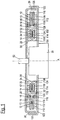
- Fig. 1 shows an embodiment of a device according to the invention in a lateral section in a schematic representation.
- the lateral section you can see two opposing printed circuit boards 10, 110 which are mutually movable about the axis A relative to each other.
- a coil 14 with coil windings which are substantially concentric with the axis of rotation A of the relative movement.
- These coil turns are on average the Fig. 1 shown schematically as only a black bar at the bottom of the printed circuit board section 10 '.
- the coil turns are formed on the respective printed circuit board by vapor-deposited or etched tracks.
- the same reference numeral 14 is used in the present text for the sake of simplicity.
- a first electrode 12 which is arranged concentrically to the rotation axis A as a conductor ring.
- the printed circuit board region of the printed circuit board 10, on which the first electrode 12 is applied, and the printed circuit board region 10 ', on which the coil 14 is applied, are connected to one another by corresponding radial webs. In the described embodiment, therefore, the coil carrier region 10 'and the electrode carrier with the first electrode 12 form a one-piece printed circuit board 10.
- the printed circuit board 10 is connected via one or more insulating spacers 16 (FIG. Fig. 1 ) is connected to a metallic housing shell 22, which may comprise, for example, a deep-drawn sheet metal.
- this housing shell 22 is rotatably connected to the drive shaft 52 of a drive motor 50, so that the housing shell 22 rotates together with the circuit board 10 and the structures applied thereto.
- the drive shaft 52 is rotatably coupled to a (not shown) first object, so that the housing shell 22 and the circuit board 10 are rotationally fixed to the first object.
- a housing of the drive motor 50 is rotatably connected to a (also not shown) second object.
- the second article is thus rotatably coupled to the printed circuit board 110.
- the housing shell 22 on the radially outer side of the printed circuit board 10 an angled portion 26. Overall, this results in a shielding structure, which is formed from the metal-lined holes 20, the annular material structure 18, the planar surface of the housing shell 22 and the angled portion 26 of the housing shell 22.
- a housing shell 122 is fixedly mounted in the described embodiment.
- This housing shell 122 carries a structure that corresponds to the structure described, which is provided in the housing shell 22, and facing it. So here is a second electrode 112 on a printed circuit board area a printed circuit board 110 which is connected via one or more insulating spacers 116 to the housing shell 122.
- An annular structure of metallic foam 118 connects the housing shell 122 with holes 120 which are annularly arranged in the printed circuit board 110 and are lined with metal. At the radially outermost region of the housing shell 122, this has an angled region 126.
- the opposing electrodes 12 and 112 on the facing circuit boards 10 and 110, respectively are effectively shielded by the shield structure formed by the housing shells 22, 122, their angled portions 26, 126, the structures of metallic foam 18 , 118 and the metal-lined annular holes 20, 120 is formed.
- the shielding is particularly effective to the outside if, as in the embodiment shown, the angled regions 26, 126 of the two housing shells 22, 122 overlap.
- the housing shells 22, 122 and in particular the angled portions 26, 126 also still form an effective capacitive coupling of the mass between the relatively rotating elements.
- the already described lithographically produced coil windings 14 are provided on the printed circuit board area 10 '. These coil windings 14 are on the in Fig. 1 lower printed circuit board 110 in the area 110 'coil turns 114 opposite, which are made lithographically the same as the coil turns 14 on the respective printed circuit board.
- the same reference numeral 114 is used herein for the coil on the circuit board 110 and the coil turns forming it.
- the printed circuit board area 10 ' is surrounded by a ferrite structure 24. It can be seen that this structure has angled portions 30, 32 which pass through the printed circuit board 10 '. In this case, the outer angled portion 32 only at the areas on cut-outs, through which pass through the web portions of the printed circuit board 10, which connect the printed circuit board area 10 'with the rest of the printed circuit board.
- the ferrite structure 24 in this way cooperates particularly effectively with a ferrite structure 124 on the other printed circuit board 110.
- the second ferrite structure 124 encloses the printed circuit board area 110 'of the second printed circuit board 110 in the same way as the ferrite structure 24 the printed circuit board area 10' of the printed circuit board 10.
- the inductive coupling between the opposing coils 14, 114 through the ferrite structures 24th , 124 effectively transformed by transformations.
- the ferrite structures 24, 124 additionally have a shielding effect in such a way that the electrical coupling of the electrodes 12, 112 for data transmission is not or less disturbed by the inductive coupling between the coils 14 and 114.
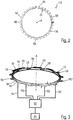
- FIG. 2 is a first embodiment of a second electrode 112 as shown in FIG Fig. 1 is used, shown in plan view.
- the annular disk-shaped second electrode 112 includes an annular portion 54 and a plurality of rectangular teeth 56 projecting outwardly from the annular portion 54. Between two teeth 56 each have a recess 58 is provided, which seen in the circumferential direction has a same length as the teeth 56.
- Fig. 3 It is shown how a second embodiment of the second electrode 112 and the first electrode 12 facing each other.
- the first electrode 12 also has teeth 56 and recesses 58, each tooth 56 encoding a one and each recess 58 a zero.
- the sequence encoded by the teeth 56 and the recesses 58 is pseudo-random.
- each two recesses 58 provided in sequence, which is followed by a tooth 56.
- All the recesses 58 and teeth 56 of the second electrode 112 are coupled to a multiplexer 60, wherein in Fig. 3 By way of example only four connecting lines 62 between the multiplexer 60 and the second electrode 112 are shown.
- the individual sections of the second electrode 112, ie the teeth 56 and the recesses 58, are each electrically insulated from one another.
- a signal with useful data is transmitted from the first electrode 12 to the second electrode 112, wherein a respective coupling strength at the teeth 56 and the recesses 58 of the second electrode 112 is determined by means of an analog-to-digital converter 64.
- the analog-to-digital converter 64 is in each case coupled by the multiplexer 60 at a time with a tooth 56 or a recess 58.
Landscapes
- Engineering & Computer Science (AREA)
- Computer Networks & Wireless Communication (AREA)
- Signal Processing (AREA)
- Physics & Mathematics (AREA)
- General Physics & Mathematics (AREA)
- Power Engineering (AREA)
- Measurement Of Length, Angles, Or The Like Using Electric Or Magnetic Means (AREA)
Applications Claiming Priority (1)
| Application Number | Priority Date | Filing Date | Title |
|---|---|---|---|
| DE102015121432.6A DE102015121432A1 (de) | 2015-12-09 | 2015-12-09 | Vorrichtung zur kontaktlosen Übertragung von Daten und zur Ermittlung einer Winkeländerung zwischen zwei sich relativ zueinander bewegenden Gegenständen |
Publications (2)
| Publication Number | Publication Date |
|---|---|
| EP3179638A1 true EP3179638A1 (fr) | 2017-06-14 |
| EP3179638B1 EP3179638B1 (fr) | 2020-02-12 |
Family
ID=57321139
Family Applications (1)
| Application Number | Title | Priority Date | Filing Date |
|---|---|---|---|
| EP16198312.7A Active EP3179638B1 (fr) | 2015-12-09 | 2016-11-11 | Dispositif de transmission sans contact de donnees et destiné à déterminer la modification angulaire entre deux objets se deplaçant l'un par rapport à l'autre |
Country Status (2)
| Country | Link |
|---|---|
| EP (1) | EP3179638B1 (fr) |
| DE (1) | DE102015121432A1 (fr) |
Cited By (10)
| Publication number | Priority date | Publication date | Assignee | Title |
|---|---|---|---|---|
| US11050389B2 (en) | 2017-04-24 | 2021-06-29 | Macom Technology Solutions Holdings, Inc. | Inverted Doherty power amplifier with large RF and instantaneous bandwidths |
| US11159125B2 (en) | 2017-04-24 | 2021-10-26 | Macom Technology Solutions Holdings, Inc. | Inverted Doherty power amplifier with large RF fractional and instantaneous bandwidths |
| US11190143B2 (en) | 2017-08-14 | 2021-11-30 | Macom Technology Solutions Holdings, Inc. | Broadband, high-efficiency, non-modulating power amplifier architecture |
| US11233483B2 (en) | 2017-02-02 | 2022-01-25 | Macom Technology Solutions Holdings, Inc. | 90-degree lumped and distributed Doherty impedance inverter |
| US11245363B2 (en) | 2017-04-24 | 2022-02-08 | Macom Technology Solutions Holdings, Inc. | Efficiency, symmetrical Doherty power amplifier |
| US11283410B2 (en) | 2017-10-02 | 2022-03-22 | Macom Technology Solutions Holdings, Inc. | No-load-modulation, high-efficiency power amplifier |
| US11705869B2 (en) | 2018-10-05 | 2023-07-18 | Macom Technology Solutions Holdings, Inc. | Low-load-modulation power amplifier |
| WO2023221953A1 (fr) * | 2022-05-20 | 2023-11-23 | 唐山工业职业技术学院 | Codeur magnétoélectrique multi-antipode haute précision |
| US11888448B2 (en) | 2019-12-30 | 2024-01-30 | Macom Technology Solutions Holdings, Inc. | Low-load-modulation broadband amplifier |
| US12028022B2 (en) | 2020-12-10 | 2024-07-02 | Macom Technology Solutions Holdings, Inc. | Hybrid power amplifier with GaN-on-Si and GaN-on-SiC circuits |
Families Citing this family (1)
| Publication number | Priority date | Publication date | Assignee | Title |
|---|---|---|---|---|
| WO2021094576A1 (fr) | 2019-11-14 | 2021-05-20 | Schleifring Gmbh | Joint rotatif intégré compact doté d'un blindage résonant |
Citations (4)
| Publication number | Priority date | Publication date | Assignee | Title |
|---|---|---|---|---|
| DE4120650A1 (de) * | 1991-06-22 | 1992-12-24 | Kolbenschmidt Ag | Vorrichtung zur uebertragung von elektrischer energie und daten in kraftfahrzeugen |
| US5598153A (en) * | 1991-12-30 | 1997-01-28 | Brasseur; Georg | Capacitive angular displacement transducer |
| DE102009044618A1 (de) * | 2008-12-15 | 2010-06-17 | FANUC LTD, Oshino-mura | Kapazitive Codiervorrichtung |
| WO2012041554A1 (fr) * | 2010-09-28 | 2012-04-05 | Schleifring Und Apparatebau Gmbh | Articulation rotoïde sans contact |
Family Cites Families (8)
| Publication number | Priority date | Publication date | Assignee | Title |
|---|---|---|---|---|
| US3702467A (en) * | 1971-11-23 | 1972-11-07 | Ibm | Shaft position sensing device |
| SE411392B (sv) * | 1977-12-09 | 1979-12-17 | Inst Mikrovagsteknik Vid Tekni | Metanordning for kapacitiv bestemning av det inbordes leget hos tva relativt varandra rorliga delar |
| DE3637529A1 (de) * | 1986-09-02 | 1988-03-17 | Hengstler Gmbh | Kapazitiver linear- oder drehgeber zum steuern und positionieren von bewegten gegenstaenden |
| DE19652935B4 (de) * | 1996-12-19 | 2005-04-21 | Valeo Schalter Und Sensoren Gmbh | Mit einem Resolver versehene Meßeinrichtung zur Messung des Lenkwinkels eines Fahrzeugs |
| SE516952C2 (sv) * | 2000-09-04 | 2002-03-26 | Johansson Ab C E | Vinkelgivare |
| DE10244547B4 (de) * | 2002-09-25 | 2010-11-11 | Dr. Johannes Heidenhain Gmbh | Verfahren und Positionsmesseinrichtung zur Bestimmung einer absoluten Position |
| DE102012112985B3 (de) * | 2012-12-21 | 2013-12-12 | Sick Ag | Entfernungsmessender optoelektronischer Sensor und Verfahren zur Erfassung und Abstandsbestimmung von Objekten |
| DE102014101312B3 (de) * | 2014-02-04 | 2014-12-04 | Sick Ag | Optoelektronischer Sensor und Verfahren zur Erfassung von Objekten in einem Überwachungsbereich |
-
2015
- 2015-12-09 DE DE102015121432.6A patent/DE102015121432A1/de not_active Ceased
-
2016
- 2016-11-11 EP EP16198312.7A patent/EP3179638B1/fr active Active
Patent Citations (4)
| Publication number | Priority date | Publication date | Assignee | Title |
|---|---|---|---|---|
| DE4120650A1 (de) * | 1991-06-22 | 1992-12-24 | Kolbenschmidt Ag | Vorrichtung zur uebertragung von elektrischer energie und daten in kraftfahrzeugen |
| US5598153A (en) * | 1991-12-30 | 1997-01-28 | Brasseur; Georg | Capacitive angular displacement transducer |
| DE102009044618A1 (de) * | 2008-12-15 | 2010-06-17 | FANUC LTD, Oshino-mura | Kapazitive Codiervorrichtung |
| WO2012041554A1 (fr) * | 2010-09-28 | 2012-04-05 | Schleifring Und Apparatebau Gmbh | Articulation rotoïde sans contact |
Cited By (17)
| Publication number | Priority date | Publication date | Assignee | Title |
|---|---|---|---|---|
| US11233483B2 (en) | 2017-02-02 | 2022-01-25 | Macom Technology Solutions Holdings, Inc. | 90-degree lumped and distributed Doherty impedance inverter |
| US11722101B2 (en) | 2017-02-02 | 2023-08-08 | Macom Technology Solutions Holdings, Inc. | 90-degree lumped and distributed Doherty impedance inverter |
| US11245363B2 (en) | 2017-04-24 | 2022-02-08 | Macom Technology Solutions Holdings, Inc. | Efficiency, symmetrical Doherty power amplifier |
| US11990871B2 (en) | 2017-04-24 | 2024-05-21 | Macom Technology Solutions Holdings, Inc. | Inverted Doherty power amplifier with large RF fractional and instantaneous bandwidths |
| US11050389B2 (en) | 2017-04-24 | 2021-06-29 | Macom Technology Solutions Holdings, Inc. | Inverted Doherty power amplifier with large RF and instantaneous bandwidths |
| US11159125B2 (en) | 2017-04-24 | 2021-10-26 | Macom Technology Solutions Holdings, Inc. | Inverted Doherty power amplifier with large RF fractional and instantaneous bandwidths |
| US11811366B2 (en) | 2017-04-24 | 2023-11-07 | Macom Technology Solutions Holdings, Inc. | Symmetrical Doherty power amplifier having improved efficiency |
| US12381515B2 (en) | 2017-04-24 | 2025-08-05 | Macom Technology Solutions Holdings, Inc. | Symmetrical Doherty power amplifier having improved efficiency |
| US11843352B2 (en) | 2017-04-24 | 2023-12-12 | Macom Technology Solutions Holdings, Inc. | Inverted Doherty power amplifier with large RF and instantaneous bandwidths |
| US11190143B2 (en) | 2017-08-14 | 2021-11-30 | Macom Technology Solutions Holdings, Inc. | Broadband, high-efficiency, non-modulating power amplifier architecture |
| US12136901B2 (en) | 2017-08-14 | 2024-11-05 | Macom Technology Solutions Holdings, Inc. | Broadband, high-efficiency, non-modulating power amplifier architecture |
| US11283410B2 (en) | 2017-10-02 | 2022-03-22 | Macom Technology Solutions Holdings, Inc. | No-load-modulation, high-efficiency power amplifier |
| US11716058B2 (en) | 2017-10-02 | 2023-08-01 | Macom Technology Solutions Holdings, Inc. | No-load-modulation, high-efficiency power amplifier |
| US11705869B2 (en) | 2018-10-05 | 2023-07-18 | Macom Technology Solutions Holdings, Inc. | Low-load-modulation power amplifier |
| US11888448B2 (en) | 2019-12-30 | 2024-01-30 | Macom Technology Solutions Holdings, Inc. | Low-load-modulation broadband amplifier |
| US12028022B2 (en) | 2020-12-10 | 2024-07-02 | Macom Technology Solutions Holdings, Inc. | Hybrid power amplifier with GaN-on-Si and GaN-on-SiC circuits |
| WO2023221953A1 (fr) * | 2022-05-20 | 2023-11-23 | 唐山工业职业技术学院 | Codeur magnétoélectrique multi-antipode haute précision |
Also Published As
| Publication number | Publication date |
|---|---|
| DE102015121432A1 (de) | 2017-06-14 |
| EP3179638B1 (fr) | 2020-02-12 |
Similar Documents
| Publication | Publication Date | Title |
|---|---|---|
| EP3179638B1 (fr) | Dispositif de transmission sans contact de donnees et destiné à déterminer la modification angulaire entre deux objets se deplaçant l'un par rapport à l'autre | |
| EP3070723B1 (fr) | Dispositif de transmission de donnees et d'energie entre deux objets se deplaçant l'un par rapport a l'autre | |
| EP2743649B1 (fr) | Dispositif de mesure de position inductif | |
| EP1464935A1 (fr) | Appareil pour détecter le couple de rotation d'un arbre rotatif | |
| EP3510362B1 (fr) | Capteur de position angulaire, élément statorique et élément rotorique pour ce dernier | |
| EP2933655A1 (fr) | Capteur optoélectronique et procédé destiné à la détection d'objets dans une zone de surveillance | |
| EP2568582B1 (fr) | Machine électrique | |
| EP2893359B1 (fr) | Palier résolveur | |
| EP1475604A2 (fr) | Capteur d'angle inductif | |
| DE102014207885A1 (de) | Fremdkörpererfassungsvorrichtung und Leistungs-Induktivladevorrichtung | |
| DE19859557A1 (de) | Drehverbinder mit Drehwinkelnachweisfunktion | |
| DE102019128928B3 (de) | Sensor und Verfahren zur Herstellung einer induktiven Energieübertragungseinheit | |
| DE102018113379A1 (de) | Drehwinkelerfassungseinrichtung, Drehwinkelerfassungsanordnung, Leistungserfassungsvorrichtung und Verfahren zur Drehwinkelerfassung | |
| DE102015208837B4 (de) | Sensoranordnung mit einem Winkelsensor sowie Wälzlageranordnung mit Sensoranordnung | |
| EP2834601B1 (fr) | Procédé et ensemble pour déterminer la position d'un composant | |
| WO1992014121A1 (fr) | Dispositif de mesure de mouvement angulaire | |
| EP1149012B1 (fr) | Dispositif pour detecter la position angulaire du volant d'une automobile | |
| WO2006008274A1 (fr) | Support mobile destine a un dispositif a rayons x | |
| WO2016045816A1 (fr) | Ensemble formant capteur pour mesurer un déplacement et/ou un angle | |
| DE102010029640B4 (de) | Drehgeberzahnvorrichtung | |
| EP3104128B1 (fr) | Dispositif de transmission sans contact de donnees et destine a determiner la modification angulaire entre deux objets se deplaçant l'un par rapport a l'autre | |
| DE20305732U1 (de) | Vorrichtung zum Bestimmen eines auf eine Welle ausgeübten Drehmoments | |
| EP3179217B1 (fr) | Dispositif de transmission sans contact de donnees et destiné à déterminer la modification angulaire entre deux objets se deplaçant l'un par rapport à l'autre | |
| EP1600737B1 (fr) | Dispositif de mesure d'angle de rotation | |
| DE202015101334U1 (de) | Vorrichtung zur Übertragung von Daten und Energie zwischen zwei sich relativ zueinander bewegenden Gegenständen |
Legal Events
| Date | Code | Title | Description |
|---|---|---|---|
| PUAI | Public reference made under article 153(3) epc to a published international application that has entered the european phase |
Free format text: ORIGINAL CODE: 0009012 |
|
| STAA | Information on the status of an ep patent application or granted ep patent |
Free format text: STATUS: THE APPLICATION HAS BEEN PUBLISHED |
|
| AK | Designated contracting states |
Kind code of ref document: A1 Designated state(s): AL AT BE BG CH CY CZ DE DK EE ES FI FR GB GR HR HU IE IS IT LI LT LU LV MC MK MT NL NO PL PT RO RS SE SI SK SM TR |
|
| AX | Request for extension of the european patent |
Extension state: BA ME |
|
| STAA | Information on the status of an ep patent application or granted ep patent |
Free format text: STATUS: REQUEST FOR EXAMINATION WAS MADE |
|
| 17P | Request for examination filed |
Effective date: 20171030 |
|
| RBV | Designated contracting states (corrected) |
Designated state(s): AL AT BE BG CH CY CZ DE DK EE ES FI FR GB GR HR HU IE IS IT LI LT LU LV MC MK MT NL NO PL PT RO RS SE SI SK SM TR |
|
| STAA | Information on the status of an ep patent application or granted ep patent |
Free format text: STATUS: EXAMINATION IS IN PROGRESS |
|
| 17Q | First examination report despatched |
Effective date: 20180228 |
|
| RIC1 | Information provided on ipc code assigned before grant |
Ipc: H04N 1/00 20060101AFI20190402BHEP |
|
| GRAP | Despatch of communication of intention to grant a patent |
Free format text: ORIGINAL CODE: EPIDOSNIGR1 |
|
| STAA | Information on the status of an ep patent application or granted ep patent |
Free format text: STATUS: GRANT OF PATENT IS INTENDED |
|
| INTG | Intention to grant announced |
Effective date: 20190516 |
|
| GRAJ | Information related to disapproval of communication of intention to grant by the applicant or resumption of examination proceedings by the epo deleted |
Free format text: ORIGINAL CODE: EPIDOSDIGR1 |
|
| STAA | Information on the status of an ep patent application or granted ep patent |
Free format text: STATUS: EXAMINATION IS IN PROGRESS |
|
| GRAP | Despatch of communication of intention to grant a patent |
Free format text: ORIGINAL CODE: EPIDOSNIGR1 |
|
| STAA | Information on the status of an ep patent application or granted ep patent |
Free format text: STATUS: GRANT OF PATENT IS INTENDED |
|
| INTC | Intention to grant announced (deleted) | ||
| RIC1 | Information provided on ipc code assigned before grant |
Ipc: G01B 7/30 20060101ALI20190719BHEP Ipc: G01D 5/241 20060101ALI20190719BHEP Ipc: H04B 5/00 20060101AFI20190719BHEP |
|
| INTG | Intention to grant announced |
Effective date: 20190816 |
|
| GRAS | Grant fee paid |
Free format text: ORIGINAL CODE: EPIDOSNIGR3 |
|
| GRAA | (expected) grant |
Free format text: ORIGINAL CODE: 0009210 |
|
| STAA | Information on the status of an ep patent application or granted ep patent |
Free format text: STATUS: THE PATENT HAS BEEN GRANTED |
|
| AK | Designated contracting states |
Kind code of ref document: B1 Designated state(s): AL AT BE BG CH CY CZ DE DK EE ES FI FR GB GR HR HU IE IS IT LI LT LU LV MC MK MT NL NO PL PT RO RS SE SI SK SM TR |
|
| REG | Reference to a national code |
Ref country code: GB Ref legal event code: FG4D Free format text: NOT ENGLISH |
|
| REG | Reference to a national code |
Ref country code: CH Ref legal event code: EP |
|
| REG | Reference to a national code |
Ref country code: AT Ref legal event code: REF Ref document number: 1233470 Country of ref document: AT Kind code of ref document: T Effective date: 20200215 |
|
| RAP2 | Party data changed (patent owner data changed or rights of a patent transferred) |
Owner name: SICK AG |
|
| REG | Reference to a national code |
Ref country code: IE Ref legal event code: FG4D Free format text: LANGUAGE OF EP DOCUMENT: GERMAN |
|
| REG | Reference to a national code |
Ref country code: DE Ref legal event code: R096 Ref document number: 502016008688 Country of ref document: DE |
|
| PG25 | Lapsed in a contracting state [announced via postgrant information from national office to epo] |
Ref country code: RS Free format text: LAPSE BECAUSE OF FAILURE TO SUBMIT A TRANSLATION OF THE DESCRIPTION OR TO PAY THE FEE WITHIN THE PRESCRIBED TIME-LIMIT Effective date: 20200212 Ref country code: FI Free format text: LAPSE BECAUSE OF FAILURE TO SUBMIT A TRANSLATION OF THE DESCRIPTION OR TO PAY THE FEE WITHIN THE PRESCRIBED TIME-LIMIT Effective date: 20200212 Ref country code: NO Free format text: LAPSE BECAUSE OF FAILURE TO SUBMIT A TRANSLATION OF THE DESCRIPTION OR TO PAY THE FEE WITHIN THE PRESCRIBED TIME-LIMIT Effective date: 20200512 |
|
| REG | Reference to a national code |
Ref country code: LT Ref legal event code: MG4D |
|
| REG | Reference to a national code |
Ref country code: NL Ref legal event code: MP Effective date: 20200212 |
|
| PG25 | Lapsed in a contracting state [announced via postgrant information from national office to epo] |
Ref country code: IS Free format text: LAPSE BECAUSE OF FAILURE TO SUBMIT A TRANSLATION OF THE DESCRIPTION OR TO PAY THE FEE WITHIN THE PRESCRIBED TIME-LIMIT Effective date: 20200612 Ref country code: BG Free format text: LAPSE BECAUSE OF FAILURE TO SUBMIT A TRANSLATION OF THE DESCRIPTION OR TO PAY THE FEE WITHIN THE PRESCRIBED TIME-LIMIT Effective date: 20200512 Ref country code: HR Free format text: LAPSE BECAUSE OF FAILURE TO SUBMIT A TRANSLATION OF THE DESCRIPTION OR TO PAY THE FEE WITHIN THE PRESCRIBED TIME-LIMIT Effective date: 20200212 Ref country code: LV Free format text: LAPSE BECAUSE OF FAILURE TO SUBMIT A TRANSLATION OF THE DESCRIPTION OR TO PAY THE FEE WITHIN THE PRESCRIBED TIME-LIMIT Effective date: 20200212 Ref country code: SE Free format text: LAPSE BECAUSE OF FAILURE TO SUBMIT A TRANSLATION OF THE DESCRIPTION OR TO PAY THE FEE WITHIN THE PRESCRIBED TIME-LIMIT Effective date: 20200212 Ref country code: GR Free format text: LAPSE BECAUSE OF FAILURE TO SUBMIT A TRANSLATION OF THE DESCRIPTION OR TO PAY THE FEE WITHIN THE PRESCRIBED TIME-LIMIT Effective date: 20200513 |
|
| PG25 | Lapsed in a contracting state [announced via postgrant information from national office to epo] |
Ref country code: NL Free format text: LAPSE BECAUSE OF FAILURE TO SUBMIT A TRANSLATION OF THE DESCRIPTION OR TO PAY THE FEE WITHIN THE PRESCRIBED TIME-LIMIT Effective date: 20200212 |
|
| PG25 | Lapsed in a contracting state [announced via postgrant information from national office to epo] |
Ref country code: LT Free format text: LAPSE BECAUSE OF FAILURE TO SUBMIT A TRANSLATION OF THE DESCRIPTION OR TO PAY THE FEE WITHIN THE PRESCRIBED TIME-LIMIT Effective date: 20200212 Ref country code: DK Free format text: LAPSE BECAUSE OF FAILURE TO SUBMIT A TRANSLATION OF THE DESCRIPTION OR TO PAY THE FEE WITHIN THE PRESCRIBED TIME-LIMIT Effective date: 20200212 Ref country code: PT Free format text: LAPSE BECAUSE OF FAILURE TO SUBMIT A TRANSLATION OF THE DESCRIPTION OR TO PAY THE FEE WITHIN THE PRESCRIBED TIME-LIMIT Effective date: 20200705 Ref country code: EE Free format text: LAPSE BECAUSE OF FAILURE TO SUBMIT A TRANSLATION OF THE DESCRIPTION OR TO PAY THE FEE WITHIN THE PRESCRIBED TIME-LIMIT Effective date: 20200212 Ref country code: SM Free format text: LAPSE BECAUSE OF FAILURE TO SUBMIT A TRANSLATION OF THE DESCRIPTION OR TO PAY THE FEE WITHIN THE PRESCRIBED TIME-LIMIT Effective date: 20200212 Ref country code: SK Free format text: LAPSE BECAUSE OF FAILURE TO SUBMIT A TRANSLATION OF THE DESCRIPTION OR TO PAY THE FEE WITHIN THE PRESCRIBED TIME-LIMIT Effective date: 20200212 Ref country code: ES Free format text: LAPSE BECAUSE OF FAILURE TO SUBMIT A TRANSLATION OF THE DESCRIPTION OR TO PAY THE FEE WITHIN THE PRESCRIBED TIME-LIMIT Effective date: 20200212 Ref country code: RO Free format text: LAPSE BECAUSE OF FAILURE TO SUBMIT A TRANSLATION OF THE DESCRIPTION OR TO PAY THE FEE WITHIN THE PRESCRIBED TIME-LIMIT Effective date: 20200212 Ref country code: CZ Free format text: LAPSE BECAUSE OF FAILURE TO SUBMIT A TRANSLATION OF THE DESCRIPTION OR TO PAY THE FEE WITHIN THE PRESCRIBED TIME-LIMIT Effective date: 20200212 |
|
| REG | Reference to a national code |
Ref country code: DE Ref legal event code: R097 Ref document number: 502016008688 Country of ref document: DE |
|
| PLBE | No opposition filed within time limit |
Free format text: ORIGINAL CODE: 0009261 |
|
| STAA | Information on the status of an ep patent application or granted ep patent |
Free format text: STATUS: NO OPPOSITION FILED WITHIN TIME LIMIT |
|
| 26N | No opposition filed |
Effective date: 20201113 |
|
| PG25 | Lapsed in a contracting state [announced via postgrant information from national office to epo] |
Ref country code: IT Free format text: LAPSE BECAUSE OF FAILURE TO SUBMIT A TRANSLATION OF THE DESCRIPTION OR TO PAY THE FEE WITHIN THE PRESCRIBED TIME-LIMIT Effective date: 20200212 |
|
| PG25 | Lapsed in a contracting state [announced via postgrant information from national office to epo] |
Ref country code: PL Free format text: LAPSE BECAUSE OF FAILURE TO SUBMIT A TRANSLATION OF THE DESCRIPTION OR TO PAY THE FEE WITHIN THE PRESCRIBED TIME-LIMIT Effective date: 20200212 Ref country code: SI Free format text: LAPSE BECAUSE OF FAILURE TO SUBMIT A TRANSLATION OF THE DESCRIPTION OR TO PAY THE FEE WITHIN THE PRESCRIBED TIME-LIMIT Effective date: 20200212 |
|
| PG25 | Lapsed in a contracting state [announced via postgrant information from national office to epo] |
Ref country code: MC Free format text: LAPSE BECAUSE OF FAILURE TO SUBMIT A TRANSLATION OF THE DESCRIPTION OR TO PAY THE FEE WITHIN THE PRESCRIBED TIME-LIMIT Effective date: 20200212 |
|
| REG | Reference to a national code |
Ref country code: CH Ref legal event code: PL |
|
| GBPC | Gb: european patent ceased through non-payment of renewal fee |
Effective date: 20201111 |
|
| PG25 | Lapsed in a contracting state [announced via postgrant information from national office to epo] |
Ref country code: LU Free format text: LAPSE BECAUSE OF NON-PAYMENT OF DUE FEES Effective date: 20201111 |
|
| REG | Reference to a national code |
Ref country code: BE Ref legal event code: MM Effective date: 20201130 |
|
| PG25 | Lapsed in a contracting state [announced via postgrant information from national office to epo] |
Ref country code: CH Free format text: LAPSE BECAUSE OF NON-PAYMENT OF DUE FEES Effective date: 20201130 Ref country code: LI Free format text: LAPSE BECAUSE OF NON-PAYMENT OF DUE FEES Effective date: 20201130 |
|
| PG25 | Lapsed in a contracting state [announced via postgrant information from national office to epo] |
Ref country code: IE Free format text: LAPSE BECAUSE OF NON-PAYMENT OF DUE FEES Effective date: 20201111 |
|
| PG25 | Lapsed in a contracting state [announced via postgrant information from national office to epo] |
Ref country code: GB Free format text: LAPSE BECAUSE OF NON-PAYMENT OF DUE FEES Effective date: 20201111 |
|
| PGFP | Annual fee paid to national office [announced via postgrant information from national office to epo] |
Ref country code: AT Payment date: 20211117 Year of fee payment: 6 |
|
| PG25 | Lapsed in a contracting state [announced via postgrant information from national office to epo] |
Ref country code: TR Free format text: LAPSE BECAUSE OF FAILURE TO SUBMIT A TRANSLATION OF THE DESCRIPTION OR TO PAY THE FEE WITHIN THE PRESCRIBED TIME-LIMIT Effective date: 20200212 Ref country code: MT Free format text: LAPSE BECAUSE OF FAILURE TO SUBMIT A TRANSLATION OF THE DESCRIPTION OR TO PAY THE FEE WITHIN THE PRESCRIBED TIME-LIMIT Effective date: 20200212 Ref country code: CY Free format text: LAPSE BECAUSE OF FAILURE TO SUBMIT A TRANSLATION OF THE DESCRIPTION OR TO PAY THE FEE WITHIN THE PRESCRIBED TIME-LIMIT Effective date: 20200212 |
|
| PG25 | Lapsed in a contracting state [announced via postgrant information from national office to epo] |
Ref country code: MK Free format text: LAPSE BECAUSE OF FAILURE TO SUBMIT A TRANSLATION OF THE DESCRIPTION OR TO PAY THE FEE WITHIN THE PRESCRIBED TIME-LIMIT Effective date: 20200212 Ref country code: AL Free format text: LAPSE BECAUSE OF FAILURE TO SUBMIT A TRANSLATION OF THE DESCRIPTION OR TO PAY THE FEE WITHIN THE PRESCRIBED TIME-LIMIT Effective date: 20200212 |
|
| PG25 | Lapsed in a contracting state [announced via postgrant information from national office to epo] |
Ref country code: BE Free format text: LAPSE BECAUSE OF NON-PAYMENT OF DUE FEES Effective date: 20201130 |
|
| REG | Reference to a national code |
Ref country code: AT Ref legal event code: MM01 Ref document number: 1233470 Country of ref document: AT Kind code of ref document: T Effective date: 20221111 |
|
| PG25 | Lapsed in a contracting state [announced via postgrant information from national office to epo] |
Ref country code: AT Free format text: LAPSE BECAUSE OF NON-PAYMENT OF DUE FEES Effective date: 20221111 |
|
| PG25 | Lapsed in a contracting state [announced via postgrant information from national office to epo] |
Ref country code: IS Free format text: LAPSE BECAUSE OF NON-PAYMENT OF DUE FEES Effective date: 20200612 |
|
| PGFP | Annual fee paid to national office [announced via postgrant information from national office to epo] |
Ref country code: DE Payment date: 20251118 Year of fee payment: 10 |
|
| PGFP | Annual fee paid to national office [announced via postgrant information from national office to epo] |
Ref country code: FR Payment date: 20251125 Year of fee payment: 10 |